media converter user manual - amazon web...
TRANSCRIPT
Media Converter userManual Models: 510486 510493 510509 510523 515320 515337 515344 515351 515368 519069
INT-MEDCON-UM-0908-01
Shown: Model 515368


introduCtion Thank you for purchasing this INTELLINET NETWORK SOLUTIONS™ Media Converter. The models listed below vary in the type and number of ports, connectors, data transfer rates and added features, but all are designed so network managers can install fiber cabling anywhere within a network without changing the arrangement of copper-based Ethernet. The compact size of the converter allows for easy deployment in any narrow desktop location or wall-mount installation and, if needed, several converters can be grouped in a 19” rack-mountable chassis.Easy-to-follow instructions in this user manual help make installation of this converter quick and simple, so you’ll also soon be enjoying the benefits of these features common to all models listed: • Auto MDI/MDI-X support • Status LEDs for easy monitoring of device status • External power adapter • Lifetime WarrantyThis user manual is included with the following items: 519069 Ethernet Media Converter 515320 Fast Ethernet Media Converter 515337 Fast Ethernet Media Converter 515344 Fast Ethernet Media Converter 510493 Gigabit Ethernet Media Converter 515351 Gigabit Ethernet Media Converter 515368 Gigabit Ethernet Media Converter 510486 Gigabit Ethernet Redundant Link Media Converter 510509 Gigabit Ethernet WDM Media Converter (RX1550/TX1310)* 510523 Gigabit Ethernet WDM Media Converter (RX1310/TX1550)*NOTE: Variations among the models can be noted in the Specifications section at the back of this manual. Product images in this manual may be representational and may not exactly match the media converter in this package.* WDM Media Converter models 510509 and 510523 need to be installed aspairsonoppositesidesofthesamefibercable.
3
FCC WarningThis device has been tested and found to comply with the limits for a Class A digital device, pursuant to Part 15 of FCC Rules. These limits are designed to provide reasonable protection against harmful interference when the equipment is operated in a commercial environment. This equipment generates, uses and radiates radio frequency energy and, if not installed and used in accordance with the user manual, may cause interference, which the user will be required to correct at his own expense.
CE Mark WarningThis is a Class A product. In a domestic environment, this product may cause radio interference, in which case the user may be required to take adequate measures to correct.
OverviewSince all the INTELLINET NETWORK SOLUTIONS Media Converter models represented in this manual do not share all the same features, refer to the product or its corresponding Specifications list to determine which of the following sections or items within the sections apply to the enclosed product. For example, not all of the LEDs defined in the status reference chart may be featured on your media converter.
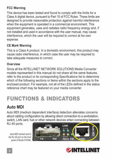
funCtions & indiCatorsAuto MDIAuto MDI (medium dependent interface) detection alleviates concerns about cabling configuration by allowing direct connection to a workstation, switch, LAN card, hub or other network devices when connecting between RJ-45 ports.
4
Auto MDI marked next to the RJ-45 port on the front
panel of Model 515386.
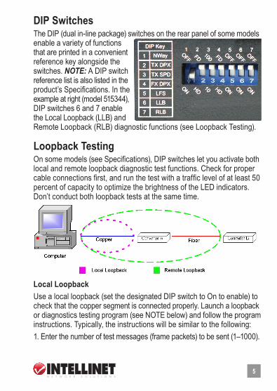
DIP SwitchesThe DIP (dual in-line package) switches on the rear panel of some models enable a variety of functions that are printed in a convenient reference key alongside the switches. NOTE: A DIP switch reference list is also listed in the product’s Specifications. In the example at right (model 515344), DIP switches 6 and 7 enable the Local Loopback (LLB) and Remote Loopback (RLB) diagnostic functions (see Loopback Testing).
Loopback TestingOn some models (see Specifications), DIP switches let you activate both local and remote loopback diagnostic test functions. Check for proper cable connections first, and run the test with a traffic level of at least 50 percent of capacity to optimize the brightness of the LED indicators. Don’t conduct both loopback tests at the same time.
Local LoopbackUse a local loopback (set the designated DIP switch to On to enable) to check that the copper segment is connected properly. Launch a loopback or diagnostics testing program (see NOTE below) and follow the program instructions. Typically, the instructions will be similar to the following: 1. Enter the number of test messages (frame packets) to be sent (1–1000).
5
2. Click “Start.”3. The program will send a testing message looped in the copper segment and display a pass/fail result.
Remote LoopbackUse a remote loopback (at the remote unit, set the designated DIP switch to On; at the local unit, keep both loopback Dip switches Off/disabled) to check that the fiber segment is connected properly. Launch a loopback or diagnostics testing program (see NOTE below) and follow the program instructions. Typically, the instructions will be similar to the following: 1. Enter the number of test messages (frame packets) to be sent (1–1000).2. Click “Start.”3. The program will send a testing message looped in the fiber segment and display a pass/fail result. NOTE: On a PC, use a program such as Sniffer to conduct the tests. Other methods include the SmartBits series of testing equipment. If you do not have access to either method, contact your vendor for advice.IMPORTANT: Deactivate both the local and the remote loopback test functions for normal converter operation.
Link Fault Signaling (LFS)Link Fault Signaling (LFS) is an important function that is extremely beneficial in terms of network status monitoring. The LFS function monitors both the copper and fiber segments to ensure that the Spanning Tree Protocol can kick in the moment a link failure occurs on either segment.Set LFS to On for normal operations; set to Off when installing cables or when testing the network connection. NOTE: The LFS feature influences both fiber and copper segments. When disruption occurs on the copper segment, the fiber segment will be disabled. When the fiber segment loses signal, the copper segment will be disabled. Any link failure — including during periods of precautionary switching to the redundant link and during Link Fault Signaling — will cause the ALM LED to light up (see LEDs). To utilize the full benefits of LFS, four converters can be used to build a primary and a secondary path between two switches. The switches must
6
support Spanning Tree or Fast Spanning Tree protocols. By default, transmission of data will travel via the primary path. If a link failure is detected, transmission will automatically be switched to the secondary path by Spanning Tree Protocol, delivering non-stop network connectivity.
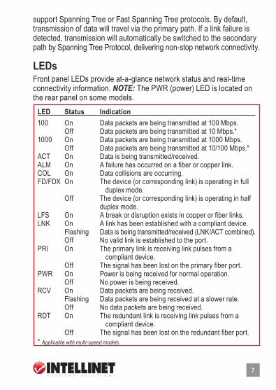
LEDsFront panel LEDs provide at-a-glance network status and real-time connectivity information. NOTE: The PWR (power) LED is located on the rear panel on some models.
7
LED Status Indication 100 On Data packets are being transmitted at 100 Mbps. Off Data packets are being transmitted at 10 Mbps.* 1000 On Data packets are being transmitted at 1000 Mbps. Off Data packets are being transmitted at 10/100 Mbps.*ACT On Data is being transmitted/received. ALM On A failure has occurred on a fiber or copper link.COL On Data collisions are occurring.FD/FDX On The device (or corresponding link) is operating in full duplex mode. Off The device (or corresponding link) is operating in half duplex mode. LFS On A break or disruption exists in copper or fiber links. LNK On A link has been established with a compliant device. Flashing Data is being transmitted/received (LNK/ACT combined). Off No valid link is established to the port.PRI On The primary link is receiving link pulses from a compliant device. Off The signal has been lost on the primary fiber port.PWR On Power is being received for normal operation. Off No power is being received.RCV On Data packets are being received. Flashing Data packets are being received at a slower rate. Off No data packets are being received. RDT On The redundant link is receiving link pulses from a compliant device. Off The signal has been lost on the redundant fiber port.* Applicablewithmulti-speedmodels.
ConneCtions & installation PortsAs mentioned in the Introduction, the type of media converter ports will vary from model to model. Refer to each model’s Specifications at the back of this manual to identify a port, and see below for explanations of their various uses and limits.
Auto MDI/MDI-XThough not a port per se, the Auto MDI/MDI-X function on a converter’s RJ-45 port alleviates concerns about cabling configuration when connecting to a 1000Base-T device. Whether connecting to a switch, a LAN card or any other network device via the RJ-45 port, simply plug it in and proceed. (See Connecting Copper Cable below.)
10/100Base-TX PortA 10/100Base-TX port supports network speeds of either 10 Mbps or 100 Mbps, and can operate in half and full duplex transfer modes. The RJ-45 connector is suitable for UTP cable Category 3, 4, 5 or better.
10/100/1000Base-T PortThe 10/100/1000Base-T port supports a network speed of 10 Mbps, 100 Mbps or 1,000 Mbps, and operates in full duplex transfer mode. The RJ-45 connector is suitable for UTP cable Category 5 or better.
10/100/1000Base-TX PortA 10/100/1000Base-TX port supports network speeds of 10 Mbps, 100 Mbps or 1,000 Mbps, and can operate in half and full duplex transfer modes. The RJ-45 connector is suitable for UTP cable Category 3, 4, 5 or better.
100Base-FX PortA 100Base-FX port adds a fiber Fast Ethernet link to your network device. Compliant with IEEE 802.3u, this port can transmit data at 100 Mbps in
8
full duplex mode across distances of up to 2 km over multi-mode fiber-optic cable. The fiber port has a choice of three fiber connector types: ST, SC or WDM.
100Base-TX PortThe 100Base-TX port supports network speed of 100 Mbps, and can operate in half and full duplex transfer modes. The RJ-45 connector is suitable for UTP cable Category 3, 4, 5 or better.
1000Base-LX PortThe 1000Base-LX port adds a fiber Gigabit Ethernet link to your network device. Compliant with IEEE 802.3z, this port transmits data at 1,000 Mbps in full duplex mode across distances of up to 220 m over multi-mode fiber- optic cable. The fiber port accepts SC or WDM connectors.
1000Base-T PortThe 1000Base-T port supports a network speed of 1,000 Mbps and operates in full duplex transfer mode. The RJ-45 connector is suitable for UTP cable Category 5 or better.
(Redundant) Gigabit SFP SlotTo connect a fiber cable’s connector to a converter’s SFP slot, slide the selected SFP module (mini-GBIC) into the SFP slot, making sure that the module’s receptors line up with the receptors at the back of the slot. Push until you hear a click. Once the module is inserted correctly, take the cable connector and turn it so that it will fit into the mouth of the module. Then push the connector into the mouth until its snaps into the receiving grooves in the module’s mouth. Use the appropriate type of multi-mode or single-mode fiber, depending on the SFP module being used. The fiber optics transmit data at up to 1,000 Mbps and can maintain data integrity over cable distances as long as 60 km, depending on the selected SFP (mini-GBIC) module.
9
Cables
Connecting Fiber CableWhen connecting fiber cable to a 1000Base-FX port on the converter, be sure an SC or WDM connector is used. (Other INTELLINET NETWORK SOLUTIONS Media Converter models may need cable that matches their ST ports.) Follow the steps below to properly connect fiber cable. 1. Remove and keep the fiber port’s rubber cover. When not connected to a fiber cable, the rubber cover should be replaced to protect the optics inside the device. 2. Check that the fiber terminators are clean. You can clean the cable plugs by wiping them gently with a clean tissue or cotton ball moistened with a little ethanol. Dirty fiber terminators on fiber optic cables will impair the quality of the light transmitted through the cable and lead to degraded performance on the port. 3. Connect one end of the cable to the SC/WDM port on the converter and the other end to the SC/WDM port on the other device. NOTE: When inserting the cable, be sure the tab on the plug clicks into position to ensure it’s properly seated. 4. Check the corresponding port LED on the converter to make sure the connection is valid.
Connecting Copper CableThe 1000Base-T RJ-45 Ethernet port fully supports auto-sensing and auto-negotiation. Follow the steps below to properly connect fiber cable. 1. Insert one end of a Category 5 twisted pair cable into the RJ-45 port on the converter and the other end into the port of the network node. 2. Check the corresponding port LED on the converter to make sure the connection is valid.
Cable Installation TipsCables can affect network performance if not installed or positioned properly. To help ensure your equipment operates at optimal levels: • Try to maintain a bend radius that’s a minimum of 4x the diameter of
10
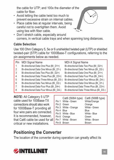
the cable for UTP; and 100x the diameter of the cable for fiber. • Avoid letting the cable twist too much to prevent excessive strain on internal cables. • Place cable ties at regular intervals, being careful not to overtighten them. Avoid using ties with fiber cable. • Don’t stretch cable, especially around corners, in vertical cable trays and when spanning long distances.
Cable Selection Use 100 Ohm Category 5, 5e or 6 unshielded twisted-pair (UTP) or shielded twisted-pair (STP) cable for 1000Base-T configurations, referring to the pin assignments below as needed.
NOTE: All Category 5 UTP cable used for 100Base-TX connections should also work for 1000Base-T providing all four wire pairs are connected. It is recommended, however, that Cat6 cable be used for all critical or new installations.
Positioning the ConverterThe location of the converter during operation can greatly affect its
11
24mm
6mm
Try to maintain a bend radius of (min.) 4x the diameter of the cable for UTP and 100x for fiber.
Try not to allow the cable to twist too much - this creates a strain on the internal cables.
Place cable ties at regular interval s - do not over tighten cable ties - try to avoid using with fiber.
Do not stretch the cable especially on corners, in vertical cable trays and when spanning long distances.
6 mm
24 mm
Cat6 (568A type) Cat6 (568B type)Pin 1 White - Green White/OrangePin 2 Green Orange Pin 3 White - Orange White - GreenPin 4 Blue BluePin 5 White - Blue White - BluePin 6 Orange Green Pin 7 White - Brown White - Brown Pin 8 Brown Brown
Pin MDI Signal Name MDI-X Signal Name1 Bi-directional Data One Plus (BI_D1+) Bi-directional Data Two Plus (BI_D2+) 2 Bi-directional Data One Minus (BI_D1-) Bi-directional Data Two Minus (BI_D2-)3 Bi-directional Data Two Plus (BI_D2+) Bi-directional Data One Plus (BI_D1+) 4 Bi-directional Data Three Plus (BI_D3+) Bi-directional Data Four Plus (BI_D4+) 5 Bi-directional Data Three Minus (BI_D3-) Bi-directional Data Four Minus (BI_D4-) 6 Bi-directional Data Two Minus (BI_D2-) Bi-directional Data One Minus (BI_D1-) 7 Bi-directional Data Four Plus (BI_D4+) Bi-directional Data Three Plus (BI_D3+) 8 Bi-directional Data Four Minus (BI_D4-) Bi-directional Data Three Minus (BI_D3-)

performance. Consider these guidelines when deciding where to place the device. • Place the converter in a fairly cool and dry location. (See Specifications for the acceptable temperature and humidity operating ranges.) • Place the converter in a location free from strong electromagnetic field generators (such as motors), vibration, dust and direct exposure to sunlight. • Place the converter in a location with easy access to AC power. • Place the converter on a clean, flat surface that leaves at least 10 cm (4 in.) of space at the front and rear of the device for ventilation. • Affix the provided rubber pads to the bottom of the converter to protect the case from scratches and prevent slipping.NOTE: For mounting on a vertical surface, use the underside of the unit as a template to measure and mark out the position of the holes on the installation surface, then use two screws to mount the converter in place. WARNING: Exercise caution if using power tools to install the device. Also, because invisible laser radiation may be emitted from the aperture of the port when no cable is connected, avoid exposure to laser radiation and do not stare into open apertures.
Powering On the ConverterThe converter uses an AC power supply: 100 – 240 V AC, 50 – 60 Hz. The power supply automatically self-adjusts to the local power source and may be powered on without having any or all LAN segment cables connected.1. Plug the power cable directly into the receptacle on the rear panel. 2. Plug the power adapter into an available socket. NOTE: For international use, you may need to change to an AC power adapter cord that has been approved for the receptacle type and electrical current in your country. 3. Confirm that the PWR LED on the rear panel is lit, indicating power to the device. If it’s not, check that the power cable is correctly plugged in.
Sample Application DiagramsTo effectively expand a Fast or Gigabit Ethernet network, position a pair of converters back to back as illustrated in the examples that follow.
12
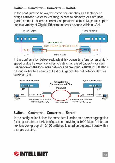
Switch — Converter — Converter — SwitchIn the configuration below, the converters function as a high-speed bridge between switches, creating increased capacity for each user (node) on the local area network and providing a 1000 Mbps full duplex link to a variety of Gigabit Ethernet network devices within a LAN.
In the configuration below, redundant link converters function as a high- speed bridge between switches, creating increased capacity for each user (node) on the local area network and providing a 10/100/1000 Mbps full duplex link to a variety of Fast or Gigabit Ethernet network devices within a LAN.
Switch — Converter — Converter — ServerIn the configuration below, the converters function as a server aggregation for an enterprise or LAN configuration, providing a 1000 Mbps full duplex link to a workgroup of 10/100 switches located on separate floors within a single building.
13
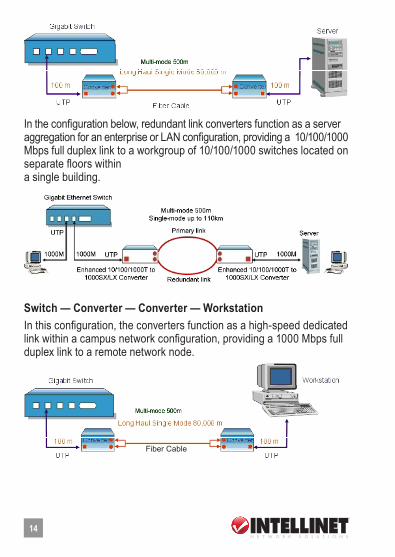
In the configuration below, redundant link converters function as a server aggregation for an enterprise or LAN configuration, providing a 10/100/1000 Mbps full duplex link to a workgroup of 10/100/1000 switches located on separate floors within a single building.
Switch — Converter — Converter — WorkstationIn this configuration, the converters function as a high-speed dedicated link within a campus network configuration, providing a 1000 Mbps full duplex link to a remote network node.
14
Fiber Cable
speCifiCations
15
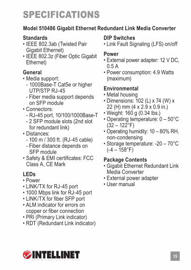
Standards • IEEE 802.3ab (Twisted Pair Gigabit Ethernet) • IEEE 802.3z (Fiber Optic Gigabit Ethernet)
General • Media support: - 1000Base-T Cat5e or higher UTP/STP RJ-45 - Fiber media support depends on SFP module • Connectors: - RJ-45 port, 10/100/1000Base-T - 2 SFP module slots (2nd slot for redundant link) • Distances: - 100 m / 300 ft. (RJ-45 cable) - Fiber distance depends on SFP module • Safety & EMI certificates: FCC Class A, CE Mark
LEDs • Power • LINK/TX for RJ-45 port • 1000 Mbps link for RJ-45 port • LINK/TX for fiber SFP port • ALM indicator for errors on copper or fiber connection • PRI (Primary Link indicator) • RDT (Redundant Link indicator)
DIP Switches • Link Fault Signaling (LFS) on/off
Power • External power adapter: 12 V DC, 0.5 A • Power consumption: 4.9 Watts (maximum)
Environmental • Metal housing • Dimensions: 102 (L) x 74 (W) x 22 (H) mm (4 x 2.9 x 0.9 in.) • Weight: 160 g (0.34 lbs.) • Operating temperature: 0 – 50°C (32 – 122°F) • Operating humidity: 10 – 80% RH, non-condensing • Storage temperature: -20 – 70°C (-4 – 158°F)
Package Contents • Gigabit Ethernet Redundant Link Media Converter • External power adapter • User manual
Model 510486 Gigabit Ethernet Redundant Link Media Converter

16
Standards • IEEE 802.3ab (Twisted Pair Gigabit Ethernet) • IEEE 802.3z (Fiber Optic Gigabit Ethernet)
General • Media support: - 1000Base-T Cat5e or higher UTP/STP RJ-45 - Fiber media support depends on SFP module • Connectors: - RJ-45 port, 1000Base-T - SFP module slot • Distances: - 100 m / 300 ft. (RJ-45 cable) - Fiber distance depends on SFP module • Safety & EMI certificates: FCC Class A, CE Mark
LEDs • Power • LINK/ACT for RJ-45 port • 1000 Mbps link for RJ-45 port • LINK/ACT for fiber SFP port • ALM indicator for errors on copper or fiber connection
DIP Switches • Link Fault Signaling (LFS) on/off
Power • External power adapter: 12 V DC, 0.5 A • Power consumption: 4.9 Watts (maximum)
Environmental • Metal housing • Dimensions: 102 (L) x 74 (W) x 22 (H) mm (4 x 2.9 x 0.9 in.) • Weight: 160 g (0.34 lbs.) • Operating temperature: 0 – 50°C (32 – 122°F) • Operating humidity: 10 – 80% RH, non-condensing • Storage temperature: -20 – 70°C (-4 – 158°F)
Package Contents • Gigabit Ethernet Media Converter • External power adapter • User manual
Model 510493 Gigabit Ethernet Media Converter
Standards • IEEE 802.3ab (Twisted Pair Gigabit Ethernet) • IEEE 802.3z (Fiber Optic Gigabit Ethernet)
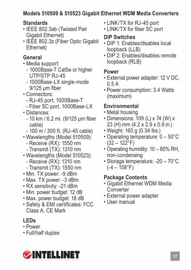
General • Media support: - 1000Base-T Cat5e or higher UTP/STP RJ-45 - 1000Base-LX single-mode 9/125 µm fiber • Connectors: - RJ-45 port, 1000Base-T - Fiber SC port, 1000Base-LX • Distances: - 10 km / 6.2 mi. (9/125 µm fiber cable) - 100 m / 300 ft. (RJ-45 cable) • Wavelengths (Model 510509): - Receive (RX): 1550 nm - Transmit (TX): 1310 nm • Wavelengths (Model 510523): - Receive (RX): 1310 nm - Transmit (TX): 1550 nm • Min. TX power: -9 dBm • Max. TX power: -3 dBm • RX sensitivity: -21 dBm • Min. power budget: 12 dB • Max. power budget: 18 dB • Safety & EMI certificates: FCC Class A, CE Mark
LEDs • Power • Full/half duplex
• LINK/TX for RJ-45 port • LINK/TX for fiber SC portDIP Switches • DIP 1: Enables/disables local loopback (LLB) • DIP 2: Enables/disables remote loopback (RLB)
Power • External power adapter: 12 V DC, 0.5 A • Power consumption: 3.4 Watts (maximum)
Environmental • Metal housing • Dimensions: 109 (L) x 74 (W) x 23 (H) mm (4.2 x 2.9 x 0.9 in.) • Weight: 160 g (0.34 lbs.) • Operating temperature: 0 – 50°C (32 – 122°F) • Operating humidity: 10 – 80% RH, non-condensing • Storage temperature: -20 – 70°C (-4 – 158°F)
Package Contents • Gigabit Ethernet WDM Media Converter • External power adapter • User manual
Models 510509 & 510523 Gigabit Ethernet WDM Media Converters
17
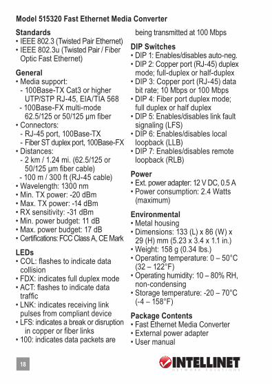
Standards • IEEE 802.3 (Twisted Pair Ethernet) • IEEE 802.3u (Twisted Pair / Fiber Optic Fast Ethernet)
General • Media support: - 100Base-TX Cat3 or higher UTP/STP RJ-45, EIA/TIA 568 - 100Base-FX multi-mode 62.5/125 or 50/125 µm fiber • Connectors: - RJ-45 port, 100Base-TX - Fiber ST duplex port, 100Base-FX • Distances: - 2 km / 1.24 mi. (62.5/125 or 50/125 µm fiber cable) - 100 m / 300 ft (RJ-45 cable) • Wavelength: 1300 nm • Min. TX power: -20 dBm • Max. TX power: -14 dBm • RX sensitivity: -31 dBm • Min. power budget: 11 dB • Max. power budget: 17 dB • Certifications: FCC Class A, CE Mark
LEDs • COL: flashes to indicate data collision • FDX: indicates full duplex mode • ACT: flashes to indicate data traffic • LNK: indicates receiving link pulses from compliant device • LFS: indicates a break or disruption in copper or fiber links • 100: indicates data packets are
being transmitted at 100 Mbps
DIP Switches • DIP 1: Enables/disables auto-neg. • DIP 2: Copper port (RJ-45) duplex mode; full-duplex or half-duplex • DIP 3: Copper port (RJ-45) data bit rate; 10 Mbps or 100 Mbps • DIP 4: Fiber port duplex mode; full duplex or half duplex • DIP 5: Enables/disables link fault signaling (LFS) • DIP 6: Enables/disables local loopback (LLB) • DIP 7: Enables/disables remote loopback (RLB)
Power • Ext. power adapter: 12 V DC, 0.5 A • Power consumption: 2.4 Watts (maximum)
Environmental • Metal housing • Dimensions: 133 (L) x 86 (W) x 29 (H) mm (5.23 x 3.4 x 1.1 in.) • Weight: 158 g (0.34 lbs.) • Operating temperature: 0 – 50°C (32 – 122°F) • Operating humidity: 10 – 80% RH, non-condensing • Storage temperature: -20 – 70°C (-4 – 158°F)
Package Contents • Fast Ethernet Media Converter • External power adapter • User manual
Model 515320 Fast Ethernet Media Converter
18

19
Standards • IEEE 802.3 (Twisted Pair Ethernet) • IEEE 802.3u (Twisted Pair / Fiber Optic Fast Ethernet)
General • Media support: - 100Base-TX Cat3 or higher UTP/STP RJ-45, EIA/TIA 568 - 100Base-FX multi-mode 62.5/125 or 50/125 µm fiber • Connectors: - RJ-45 port, 100Base-TX - Fiber SC duplex port, 100Base-FX • Distances: - 2 km / 1.24 mi. (62.5/125 or 50/125 µm fiber cable) - 100 m / 300 ft (RJ-45 cable) • Wavelength: 1300 nm • Min. TX power: -20 dBm • Max. TX power: -14 dBm • RX sensitivity: -31 dBm • Min. power budget: 11 dB • Max. power budget: 17 dB • Certifications: FCC Class A, CE Mark
LEDs • COL: flashes to indicate data collision • FDX: indicates full duplex mode • ACT: flashes to indicate data traffic • LNK: indicates receiving link pulses from compliant device • LFS: indicates a break or disruption in copper or fiber links • 100: indicates data packets are
being transmitted at 100 Mbps
DIP Switches • DIP 1: Enables/disables auto-neg. • DIP 2: Copper port (RJ-45) duplex mode; full-duplex or half-duplex • DIP 3: Copper port (RJ-45) data bit rate; 10 Mbps or 100 Mbps • DIP 4: Fiber port duplex mode; full duplex or half duplex • DIP 5: Enables/disables link fault signaling (LFS) • DIP 6: Enables/disables local loopback (LLB) • DIP 7: Enables/disables remote loopback (RLB)
Power • Ext. power adapter: 12 V DC, 0.5 A • Power consumption: 2.4 Watts (maximum)
Environmental • Metal housing • Dimensions: 133 (L) x 86 (W) x 29 (H) mm (5.23 x 3.4 x 1.1 in.) • Weight: 158 g (0.34 lbs.) • Operating temperature: 0 – 50°C (32 – 122°F) • Operating humidity: 10 – 80% RH, non-condensing • Storage temperature: -20 – 70°C (-4 – 158°F)
Package Contents • Fast Ethernet Media Converter • External power adapter • User manual
Model 515337 Fast Ethernet Media Converter
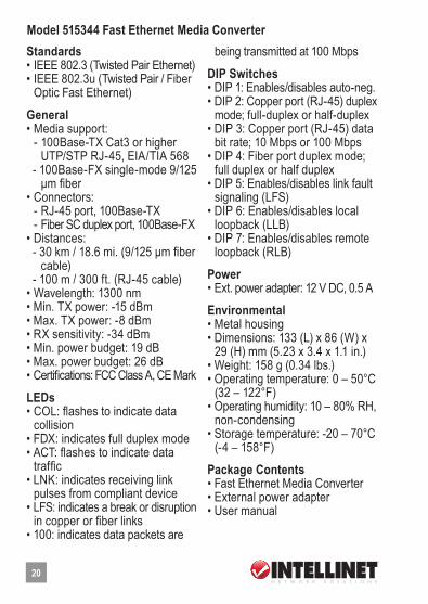
Standards • IEEE 802.3 (Twisted Pair Ethernet) • IEEE 802.3u (Twisted Pair / Fiber Optic Fast Ethernet)
General • Media support: - 100Base-TX Cat3 or higher UTP/STP RJ-45, EIA/TIA 568 - 100Base-FX single-mode 9/125 µm fiber • Connectors: - RJ-45 port, 100Base-TX - Fiber SC duplex port, 100Base-FX • Distances: - 30 km / 18.6 mi. (9/125 µm fiber cable) - 100 m / 300 ft. (RJ-45 cable) • Wavelength: 1300 nm • Min. TX power: -15 dBm • Max. TX power: -8 dBm • RX sensitivity: -34 dBm • Min. power budget: 19 dB • Max. power budget: 26 dB • Certifications: FCC Class A, CE Mark
LEDs • COL: flashes to indicate data collision • FDX: indicates full duplex mode • ACT: flashes to indicate data traffic • LNK: indicates receiving link pulses from compliant device • LFS: indicates a break or disruption in copper or fiber links • 100: indicates data packets are
being transmitted at 100 Mbps
DIP Switches • DIP 1: Enables/disables auto-neg. • DIP 2: Copper port (RJ-45) duplex mode; full-duplex or half-duplex • DIP 3: Copper port (RJ-45) data bit rate; 10 Mbps or 100 Mbps • DIP 4: Fiber port duplex mode; full duplex or half duplex • DIP 5: Enables/disables link fault signaling (LFS) • DIP 6: Enables/disables local loopback (LLB) • DIP 7: Enables/disables remote loopback (RLB)
Power • Ext. power adapter: 12 V DC, 0.5 A
Environmental • Metal housing • Dimensions: 133 (L) x 86 (W) x 29 (H) mm (5.23 x 3.4 x 1.1 in.) • Weight: 158 g (0.34 lbs.) • Operating temperature: 0 – 50°C (32 – 122°F) • Operating humidity: 10 – 80% RH, non-condensing • Storage temperature: -20 – 70°C (-4 – 158°F)
Package Contents • Fast Ethernet Media Converter • External power adapter • User manual
Model 515344 Fast Ethernet Media Converter
20
21
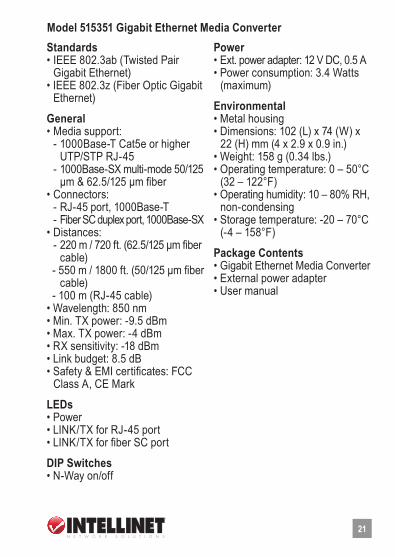
Standards • IEEE 802.3ab (Twisted Pair Gigabit Ethernet) • IEEE 802.3z (Fiber Optic Gigabit Ethernet)
General • Media support: - 1000Base-T Cat5e or higher UTP/STP RJ-45 - 1000Base-SX multi-mode 50/125 µm & 62.5/125 µm fiber • Connectors: - RJ-45 port, 1000Base-T - Fiber SC duplex port, 1000Base-SX • Distances: - 220 m / 720 ft. (62.5/125 µm fiber cable) - 550 m / 1800 ft. (50/125 µm fiber cable) - 100 m (RJ-45 cable) • Wavelength: 850 nm • Min. TX power: -9.5 dBm • Max. TX power: -4 dBm • RX sensitivity: -18 dBm • Link budget: 8.5 dB • Safety & EMI certificates: FCC Class A, CE Mark
LEDs • Power • LINK/TX for RJ-45 port • LINK/TX for fiber SC port
DIP Switches • N-Way on/off
Power • Ext. power adapter: 12 V DC, 0.5 A • Power consumption: 3.4 Watts (maximum)
Environmental • Metal housing • Dimensions: 102 (L) x 74 (W) x 22 (H) mm (4 x 2.9 x 0.9 in.) • Weight: 158 g (0.34 lbs.) • Operating temperature: 0 – 50°C (32 – 122°F) • Operating humidity: 10 – 80% RH, non-condensing • Storage temperature: -20 – 70°C (-4 – 158°F)
Package Contents • Gigabit Ethernet Media Converter • External power adapter • User manual
Model 515351 Gigabit Ethernet Media Converter
Standards • IEEE 802.3ab (Twisted Pair Gigabit Ethernet) • IEEE 802.3z (Fiber Optic Gigabit Ethernet)
General • Media support: - 1000Base-T Cat5e or higher UTP/STP RJ-45 - 1000Base-LX single-mode 9/125 µm fiber • Connectors: - RJ-45 port, 1000Base-T - Fiber SC duplex port, 1000Base-LX • Distances: - 10 km / 6.2 mi. (9/125 µm fiber cable) - 100 m / 300 ft. (RJ-45 cable) • Wavelength: 1310 nm • Min. TX power: -9.5 dBm • Max. TX power: -3 dBm • RX sensitivity: -20 dBm • Link budget: 10.5 dB • Safety & EMI certificates: FCC Class A, CE Mark
LEDs • Power • Full/half duplex • LINK/TX for RJ-45 port • LINK/TX for fiber SC port
DIP Switches • N-Way on/off
Power • Ext. power adapter: 12 V DC, 0.5 A • Power consumption: 3.4 Watts (maximum)Environmental • Metal housing • Dimensions: 102 (L) x 74 (W) x 22 (H) mm (4 x 2.9 x 0.9 in.) • Weight: 158 g (0.34 lbs.) • Operating temperature: 0 – 50°C (32 – 122°F) • Operating humidity: 10 – 80% RH, non-condensing • Storage temperature: -20 – 70°C (-4 – 158°F)
Package Contents • Gigabit Ethernet Media Converter • External power adapter • User manual
Model 515368 Gigabit Ethernet Media Converter
22
23
Standards • IEEE 802.3 (Twisted Pair Ethernet) • IEEE 802.3u (Twisted Pair / Fiber Optic Fast Ethernet)
General • Media support: - 100Base-TX Cat5e or higher UTP/STP RJ-45, EIA/TIA 568 - 100Base-FX single-mode 9/125 µm fiber • Connectors: - RJ-45 port, 100Base-TX - Fiber SC duplex port, 100Base-FX • Distances: - 30 km / 18.6 mi. (9/125 µm fiber cable) - 100 m / 300 ft. (RJ-45 cable) • Wavelength: 1310 nm • Min. TX power: -15 dBm • Max. TX power: -8 dBm • RX sensitivity: -34 dBm • Min. power budget: 19 dB • Max. power budget: 26 dB • Certifications: FCC Class A, CE Mark
LEDs • COL: flashes to indicate data collision • FDX: indicates full duplex mode • ACT: flashes to indicate data traffic • LNK: indicates receiving link pulses from compliant device • LFS: indicates a break or disruption
in copper or fiber links • 100: indicates data packets are being transmitted at 100 Mbps
Switches • MDI/MDI-X selector for RJ-45 port• Auto-Negotiation on/off
Power • Ext. power adapter: 12 V DC, 0.5 A
Environmental • Metal housing • Dimensions: 133 (L) x 86 (W) x 29 (H) mm (5.23 x 3.4 x 1.1 in.) • Weight: 158 g (0.34 lbs.) • Operating temperature: 0 – 50°C (32 – 122°F) • Operating humidity: 10 – 80% RH, non-condensing • Storage temperature: -20 – 70°C (-4 – 158°F)
Package Contents • Fast Ethernet Media Converter • External power adapter • User manual
Model 519069 Ethernet Media Converter

INTellINeT NeTWoRK solUTIoNs™ offers a complete line of active and passive networking products.
Ask your local computer dealer for more information or visit
www.intellinet-network.com.
Copyright © INTELLINET NETWORK SOLUTIONSAll products mentioned are trademarks or registered trademarks of their respective owners.