mediant 800 ucpe - audiocodes · 4 installing openstack on mediant 800 ucpe’s osn module ... the...
TRANSCRIPT

Installation Manual
AudioCodes Mediant™ Software SBC Series
Mediant 800 uCPE For Business Services
Version 6.8

Version 6.8 3 Mediant 800 uCPE
Installation Manual Contents
Table of Contents 1 Overview .............................................................................................................. 7
1.1 Hardware Overview ................................................................................................ 7 1.2 Deployment Topology ............................................................................................. 7 1.3 Typical Installation / Deployment Sequence ........................................................... 8
2 Installing Openstack Platform In Service Provider’s Data Center .................. 9
2.1 Overview ................................................................................................................ 9 2.2 Installing a Sample OpenStack Platform ................................................................. 9 2.3 Hardware Requirements ......................................................................................... 9 2.4 CentOS 7 Installation ............................................................................................ 10 2.5 Post-Installation Configuration .............................................................................. 10 2.6 OpenStack Rdo Mitaka Installation ....................................................................... 11 2.7 Creating Controller Node From Virtual Appliance ................................................. 14
3 Installing Centos 7 on Mediant 800 uCPE’S OSN Module ............................. 17
3.1 Preparing Installation USB Drive .......................................................................... 17 3.2 Starting the Installation ......................................................................................... 17 3.3 Choosing Installation Language ........................................................................... 19 3.4 Installation Summary Screen ................................................................................ 19 3.5 Selecting Software................................................................................................ 20 3.6 Configuring Network Settings ............................................................................... 20 3.7 Partitioning Hard Drive ......................................................................................... 22 3.8 Configuring Time Settings .................................................................................... 23 3.9 Starting the Software Installation .......................................................................... 24 3.10 Configuring Root Password .................................................................................. 24 3.11 Configuring Administrator User ............................................................................. 25 3.12 Completing the Installation ................................................................................... 26 3.13 Post-Installation Configuration .............................................................................. 26
4 Installing Openstack On Mediant 800 uCPE’S OSN Module .......................... 29
4.1 Pre-Requisites ...................................................................................................... 29 4.2 Network Topology ................................................................................................ 29 4.3 OpenStack Installation .......................................................................................... 31
5 Installing Pre-Built Openstack Image Mediant 800 uCPE’S OSN Module .... 33
5.1 Overview .............................................................................................................. 33 5.2 Installing Pre-Built OpenStack Image On OSN Module ........................................ 33
6 Configuring Mediant 800 uCPE’S MSBR Module............................................ 35
6.1 Connecting to Mediant 800 uCPE’S MSBR Module .............................................. 35 6.2 “Flat” (Layer 2) Networking Setup ......................................................................... 36 6.3 “Flat” (Layer 2) Networking Setup – MSBR Configuration ..................................... 37 6.4 “VPN Tunnel” (Layer 3) Networking Setup ............................................................ 38 6.5 “VPN Tunnel” (Layer 3) Networking Setup – MSBR Configuration ........................ 39
7 Configuring Management Interface on OSN Module ...................................... 41
7.1 Overview .............................................................................................................. 41
Installation Manual 4 Document #: LTRT-10603
Mediant 800 uCPE
7.2 Adding Management IP Address to the OSN Module ........................................... 41
8 Configuring OpenStack Networks ................................................................... 43
8.1 Overview .............................................................................................................. 43 8.2 Neutron Configuration .......................................................................................... 44
9 Re-configuring IP Addresses ........................................................................... 45
9.1 Overview .............................................................................................................. 45 9.2 Changing IP Address of OSN Module .................................................................. 45 9.3 Updating IP Address of Controller Node on OSN Module ..................................... 46 9.4 Changing IP Address Of Controller Node ............................................................. 46 9.5 Changing IP Addresses Of OpenStack Provider Networks ................................... 47
Version 6.8 5 Mediant 800 uCPE
Installation Manual Notices
Notice Information contained in this document is believed to be accurate and reliable at the time of printing. However, due to ongoing product improvements and revisions, AudioCodes cannot guarantee accuracy of printed material after the Date Published nor can it accept responsibility for errors or omissions. Updates to this document and other documents as well as software files can be downloaded by registered customers at http://www.audiocodes.com/downloads.
© Copyright 2017 AudioCodes Ltd. All rights reserved.
This document is subject to change without notice.
Date Published: January-03-2017
Trademarks ©2017 AudioCodes Ltd. All rights reserved. AudioCodes, AC, HD VoIP, HD VoIP Sounds Better, IPmedia, Mediant, MediaPack, What’s Inside Matters, OSN, SmartTAP, User Management Pack, VMAS, VoIPerfect, VoIPerfectHD, Your Gateway To VoIP, 3GX, VocaNom, AudioCodes One Voice and CloudBond are trademarks or registered trademarks of AudioCodes Limited. All other products or trademarks are property of their respective owners. Product specifications are subject to change without notice. .
WEEE EU Directive Pursuant to the WEEE EU Directive, electronic and electrical waste must not be disposed of with unsorted waste. Please contact your local recycling authority for disposal of this product.
Customer Support Customer technical support and services are provided by AudioCodes or by an authorized AudioCodes Service Partner. For more information on how to buy technical support for AudioCodes products and for contact information, please visit our Web site at www.audiocodes.com/support.
Abbreviations and Terminology Each abbreviation, unless widely used, is spelled out in full when first used.
Installation Manual 6 Document #: LTRT-10603
Mediant 800 uCPE
Document Revision Record
LTRT Description
LTRT-10602 Initial document release for Version 6.8
LTRT-10603 Update for changing the name of the product from vE-CPE to uCPE
Documentation Feedback AudioCodes continually strives to produce high quality documentation. If you have any comments (suggestions or errors) regarding this document, please fill out the Documentation Feedback form on our Web site at http://www.audiocodes.com/downloads.
Installation Manual 1. Overview
Version 6.8 7 Mediant 800 uCPE
1 Overview 1.1 Hardware Overview
Mediant 800 uCPE consists of two functional elements: Multi-Service Business Router (MSBR) module – Enterprise-grade Data Router that
provides complete network connectivity for the enterprise, supports multiple WAN protocols ad interfaces, implements network security functions, provides VoIP gateway and Session Border controller (SBC) functionality (if needed).
Open Solutions Network (OSN) module – Intel x86 server that operates as “compute node” managed by OpenStack platform; used for deploying virtual network functions (VNFs) at customer premises.
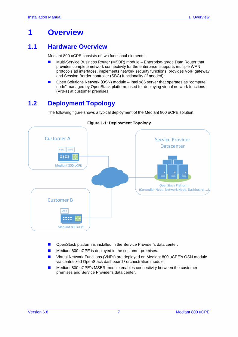
1.2 Deployment Topology The following figure shows a typical deployment of the Mediant 800 uCPE solution.
Figure 1-1: Deployment Topology
OpenStack platform is installed in the Service Provider’s data center. Mediant 800 uCPE is deployed in the customer premises. Virtual Network Functions (VNFs) are deployed on Mediant 800 uCPE’s OSN module
via centralized OpenStack dashboard / orchestration module. Mediant 800 uCPE’s MSBR module enables connectivity between the customer
premises and Service Provider’s data center.
Installation Manual 8 Document #: LTRT-10603
Mediant 800 uCPE
1.3 Typical Installation / Deployment Sequence A typical installation / deployment sequence of the Mediant 800 uCPE solution is as follows: 1. The OpenStack platform is installed in the Service Provider’s Data Center. 2. The Linux OS and OpenStack platform elements (compute and network services) are
installed on Mediant 800 uCPE’s OSN module. 3. A typical customer networking configuration is created on the Mediant 800 uCPE’s
MSBR module – to minimize required re-configuration after deployment in the customer premises.
4. The Mediant 800 uCPE is shipped to the customer premises and deployed there. 5. The Mediant 800 uCPE’s MSBR module is re-configured to enable connectivity
between the customer premises and the service provider’s data center. 6. The Mediant 800 uCPE’s OSN module is re-configured to match the networking
environment in the specific customer premises. 7. The connection between OpenStack platform and Mediant 800 uCPE is established. 8. The customer-specific virtual network functions (VNFs) are deployed on the Mediant
800 uCPE.
Installation Manual 2. Installing Openstack Platform In Service Provider’s Data Center
Version 6.8 9 Mediant 800 uCPE
2 Installing Openstack Platform In Service Provider’s Data Center
2.1 Overview To deploy the Mediant 800 uCPE solution you need to install the OpenStack platform in the data center. Such a platform should include the following functional elements: Controller Node (keystone, nova-api, nova-conductor, nova-scheduler, glance,
dashboard) Network Node (neutron) The OpenStack platform is typically pre-installed by the service provider. For the purposes of this document we will assume that the following OpenStack platform is used: CentOS 7 (http://www.centos.org) OpenStack RDO Mitaka (http://www.rdoproject.org) – community-supported
distribution of OpenStack for CentOS, Fedora and RHEL platforms. If your OpenStack environment is different, consult with your OpenStack vendor for detailed instructions on platform installation and configuration.
2.2 Installing a Sample OpenStack Platform If you don’t have the OpenStack platform already installed in the Data Center, use the following instructions in Section 2.4 to install a sample combined OpenStack controller and network node based on CentOS 7 and OpenStack RDO Mitaka. Alternatively you may use a sample Virtual Machine image as described in Section 2.7.
2.3 Hardware Requirements Use the following physical or virtual server for the OpenStack controller and network node installation: Intel x86 64-bit CPU, at least 2 cores 4GB of RAM or more 60 GB of disk or more
Installation Manual 10 Document #: LTRT-10603
Mediant 800 uCPE
2.4 CentOS 7 Installation This section describes how to install the CentOS 7 platform.
To install CentOS 7:
1. Download the CentOS 7 installation DVD ISO from https://www.centos.org/download/ 2. Burn the installation DVD ISO to DVD disk; or use a Linux machine to create an
installation USB drive: dd if=CentOS-7-x86_64-DVD.iso of=/dev/sdb
3. Install CentOS 7 on the Linux server as follows: • Software Selection:
a. select “Virtual Host” • Partitioning Hard Drive:
a. Make sure that most of the disk space is allocated under root (/) mount point; b. If you start with default disk partitioning, remove /home partition altogether
and re-allocate all space from it to root (/) partition. • Network Configuration:
a. Configure static IPv4 address, e.g. 192.168.0.50/24 b. Disable IPv6 configuration. c. Configure hostname, e.g. ”controller”.
• Time Settings: a. Select time zone. b. Enable “Network Time” synchronization.
• Root Password: a. Configure root password, e.g. “root”
• Administrator User: a. Create user with name “admin”. b. Configure password, e.g. “123456”. c. Select “Make this user administrator”.
2.5 Post-Installation Configuration This section describes post-installation configuration actions.
Do the following:
1. Login as user “root”. 2. Change SELinux mode to permissive:
# setenforce permissive # vi /etc/sysconfig/selinux ... SELINUX=permissive ...
3. Disable Network Manager: # systemctl stop NetworkManager # systemctl disable NetworkManager
4. Disable firewall: # systemctl stop firewalld # systemctl disable firewalld
Installation Manual 2. Installing Openstack Platform In Service Provider’s Data Center
Version 6.8 11 Mediant 800 uCPE
5. Disable IPv6 support for all network interfaces: # vi /etc/sysconfig/network ... IPV6INIT=no # systemctl restart network
6. Add hostname to /etc/hosts file: # vi /etc/hosts … 192.168.0.50 controller
2.6 OpenStack Rdo Mitaka Installation This section describes how to install the OpenStack Rdo Mitaka platform.
To install Rdo Mitaka:
1. Login as user “root” 2. Determine the network interface name and IP address of the machine:
# ip addr show 1: lo: <LOOPBACK,UP,LOWER_UP> mtu 16436 qdisc noqueue state UNKNOWN link/loopback 00:00:00:00:00:00 brd 00:00:00:00:00:00 inet 127.0.0.1/8 scope host lo inet6 ::1/128 scope host valid_lft forever preferred_lft forever 2: enp0s3: <BROADCAST,MULTICAST,UP,LOWER_UP> mtu 1500 qdisc mq state UP qlen 1000 link/ether 00:12:79:11:22:33 brd ff:ff:ff:ff:ff:ff inet 192.168.0.50/24 brd 192.168.0.255 scope global eth0 inet6 fe80::212:79ff:fea3:84d6/64 scope link valid_lft forever preferred_lft forever
3. Install RDO repository and Packstack deployment tool: # yum install -y centos-release-openstack-mitaka # yum install -y openstack-packstack
4. Generate “answer file”: # packstack --gen-answer-file=ans.txt
5. Edit “answer file” as follows: # vi ans.txt … CONFIG_KEYSTONE_ADMIN_PW=123456 … CONFIG_PROVISION_DEMO=n … CONFIG_HEAT_INSTALL=y … CONFIG_NOVA_COMPUTE_PRIVIF=eno1 CONFIG_NOVA_NETWORK_PUBIF=enp0s3 CONFIG_NOVA_NETWORK_PRIVIF=enp0s3
Installation Manual 12 Document #: LTRT-10603
Mediant 800 uCPE
// in the above two lines change “enp0s3” to the actual network interface name // (as determined in step 2); keep CONFIG_NOVA_COMPUTE_PRIVIF set to “eno1” // regardless of the actual network interface name … CONFIG_CONTROLLER_HOST=controller CONFIG_COMPUTE_HOSTS= CONFIG_NETWORK_HOSTS=controller CONFIG_STORAGE_HOST=controller CONFIG_SAHARA_HOST=controller CONFIG_AMQP_HOST=controller CONFIG_MARIADB_HOST=controller CONFIG_MONGODB_HOST=controller CONFIG_REDIS_MASTER_HOST=controller // if you configured different hostname, use it instead of “controller” in the above lines // keep CONFIG_COMPUTE_HOSTS empty … CONFIG_NEUTRON_ML2_TUNNEL_ID_RANGES=1001:2000 CONFIG_NEUTRON_ML2_VXLAN_GROUP=239.1.1.2 CONFIG_NEUTRON_ML2_VNI_RANGES=1001:2000 … CONFIG_NEUTRON_OVS_BRIDGE_MAPPINGS=physnet1:br-ex CONFIG_NEUTRON_OVS_BRIDGE_IFACES=br-ex:enp0s3 // in the above line change “enp0s3” to the actual network interface name machine // (as determined in step 2)
6. Run packstack with modified “answer file”: # packstack --answer-file=ans.txt
7. Wait until the installation has completed. 8. Modify the Neutron configuration to enable support for flat and VLAN provider
networks: # vi /etc/neutron/plugin.ini ... [ml2] type_drivers = vxlan,flat,vlan ... [ml2_type_flat] flat_networks = * ... # vi /etc/neutron/dhcp_agent.ini ... enable_isolated_metadata = true ...
Installation Manual 2. Installing Openstack Platform In Service Provider’s Data Center
Version 6.8 13 Mediant 800 uCPE
9. Modify the Horizon configuration file by changing the first ServerAlias to be controller node’s IP address (note this action is required as a result of a bug in Packstack implementation as of this writing – so this step may be unnecessary in the future). # vi /etc/httpd/conf.d/15-horizon_vhost.conf ... ## Server aliases ServerAlias 192.168.0.50 ServerAlias controller ServerAlias localhost
10. Reboot the machine. # reboot
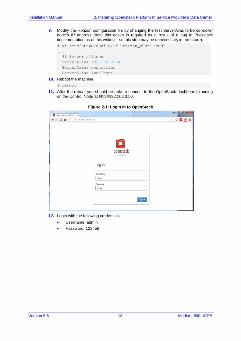
11. After the reboot you should be able to connect to the OpenStack dashboard, running on the Control Node at http://192.168.0.50.
Figure 2-1: Login In to OpenStack
12. Login with the following credentials:
• Username: admin • Password: 123456
Installation Manual 14 Document #: LTRT-10603
Mediant 800 uCPE
2.7 Creating Controller Node From Virtual Appliance Instead of installing the OpenStack Controller Node manually (as described in Section 2.6) you may use a pre-built Virtual appliance provided by AudioCodes to deploy a sample OpenStack controller node on a Virtual machine. Virtual appliance is distributed for demonstration purposes and contains CentOS 7 and OpenStack RDO Mitaka software suite installed as per the instructions provided above in Section 2.4 to 2.6. The appliance was created using the Oracle VirtualBox 5.0 Virtualization platform.
To deploy the image:
1. Download and install Oracle VirtualBox virtualization platform from http://www.virtualbox.org.
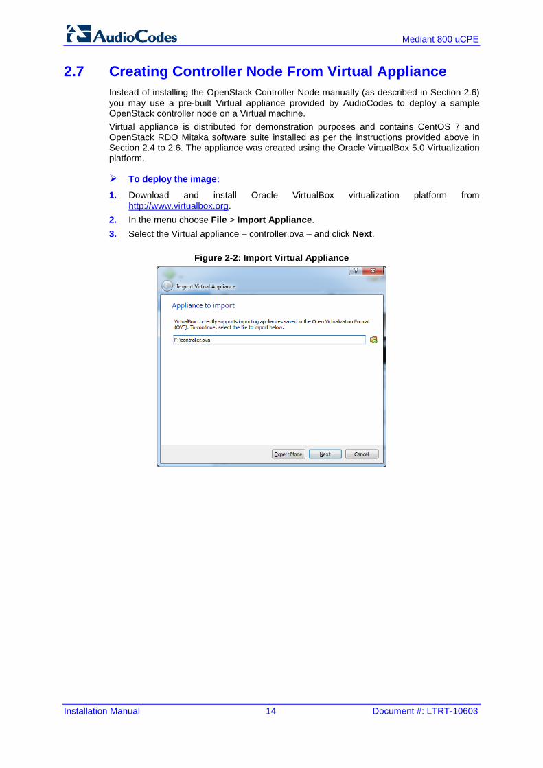
2. In the menu choose File > Import Appliance. 3. Select the Virtual appliance – controller.ova – and click Next.
Figure 2-2: Import Virtual Appliance
Installation Manual 2. Installing Openstack Platform In Service Provider’s Data Center
Version 6.8 15 Mediant 800 uCPE
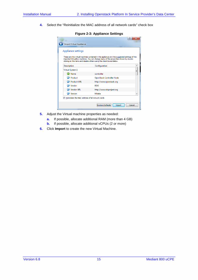
4. Select the “Reinitialize the MAC address of all network cards” check box
Figure 2-3: Appliance Settings
5. Adjust the Virtual machine properties as needed:
a. If possible, allocate additional RAM (more than 4 GB) b. If possible, allocate additional vCPUs (2 or more)
6. Click Import to create the new Virtual Machine.

Installation Manual 16 Document #: LTRT-10603
Mediant 800 uCPE
This page is intentionally left blank.
Installation Manual 3. Installing Centos 7 on Mediant 800 uCPE’S OSN Module
Version 6.8 17 Mediant 800 uCPE
3 Installing Centos 7 on Mediant 800 uCPE’S OSN Module This chapter describes the installation of CentOS 7 on the Mediant 800 uCPE’s OSN module.
3.1 Preparing Installation USB Drive Before commencing the installation, you need to prepare the installation USB drive.
Do the following:
1. Download CentOS 7 installation DVD ISO from https://www.centos.org/download/ 2. Use Linux machine to create installation USB drive
dd if=CentOS-7-x86_64-DVD.iso of=/dev/sdb
3.2 Starting the Installation This step describes how to start the installation process.
To start the installation:
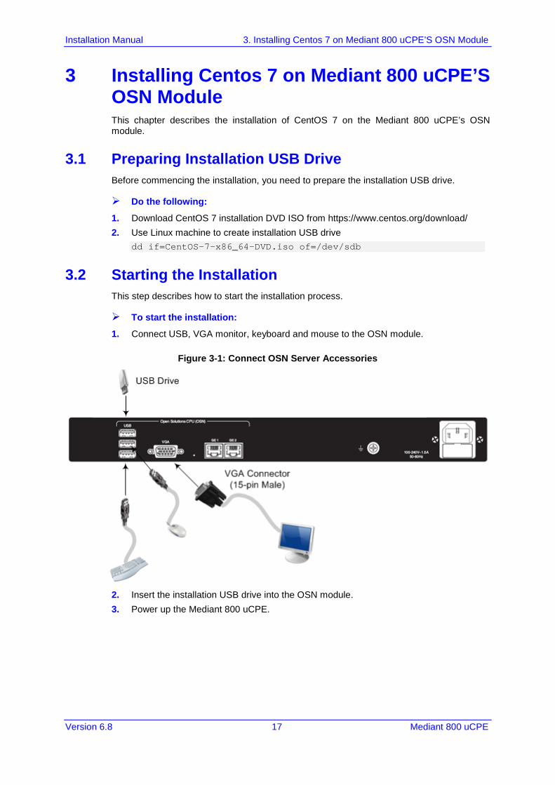
1. Connect USB, VGA monitor, keyboard and mouse to the OSN module.
Figure 3-1: Connect OSN Server Accessories
2. Insert the installation USB drive into the OSN module. 3. Power up the Mediant 800 uCPE.
Installation Manual 18 Document #: LTRT-10603
Mediant 800 uCPE
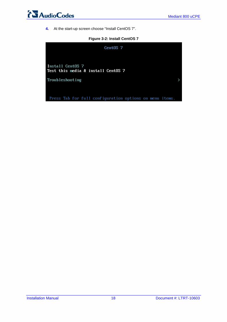
4. At the start-up screen choose “Install CentOS 7”.
Figure 3-2: Install CentOS 7

Installation Manual 3. Installing Centos 7 on Mediant 800 uCPE’S OSN Module
Version 6.8 19 Mediant 800 uCPE
3.3 Choosing Installation Language This step describes how to choose the installation language.
To choose the installation language:
At the Installation Language screen, select English / English (United States) and click Continue.
Figure 3-3: Welcome to Centos 7
3.4 Installation Summary Screen The INSTALLATION SUMMARY screen is displayed.
Figure 3-4: Installation Summary

Installation Manual 20 Document #: LTRT-10603
Mediant 800 uCPE
3.5 Selecting Software This step describes how to select software.
To select software
1. Click “SOFTWARE SELECTION” to select software that will be installed. 2. Select “Virtualization Host” and click Done.
3.6 Configuring Network Settings This step describes how to configure network settings.
To configure network settings:
1. Click NETWORK & HOSTNAME to configure network settings.
Figure 3-5: Network & Hostname-OSN
2. The OSN module has three network interfaces (different to the interfaces show in the
figure above): a. eno1 – internal interface that connects the OSN module with the MSBR data
router module. b. enp1s0 and enp4s0 – external interfaces that may be used for connecting the
OSN module to additional networks. In this Configuration manual, “eno1” is used as the primary OSN module interface.
3. Click Configure to configure the IP address of the “eno1” interface. 4. In the IPv4 Settings tab choose the Manual method and configure the following:
a. IP address: 192.168.0.100 b. Netmask: 255.255.255.0 c. Gateway: 192.168.0.1 d. DNS servers: 192.168.0.1
Installation Manual 3. Installing Centos 7 on Mediant 800 uCPE’S OSN Module
Version 6.8 21 Mediant 800 uCPE
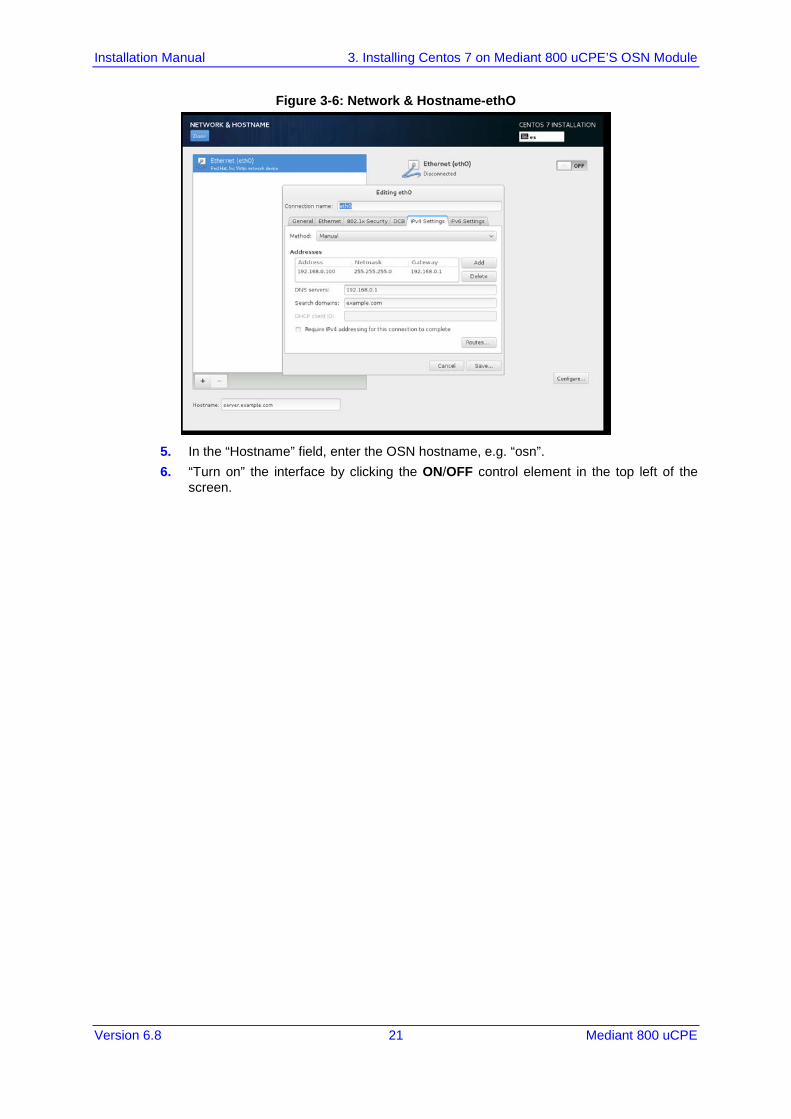
Figure 3-6: Network & Hostname-ethO
5. In the “Hostname” field, enter the OSN hostname, e.g. “osn”. 6. “Turn on” the interface by clicking the ON/OFF control element in the top left of the
screen.
Installation Manual 22 Document #: LTRT-10603
Mediant 800 uCPE
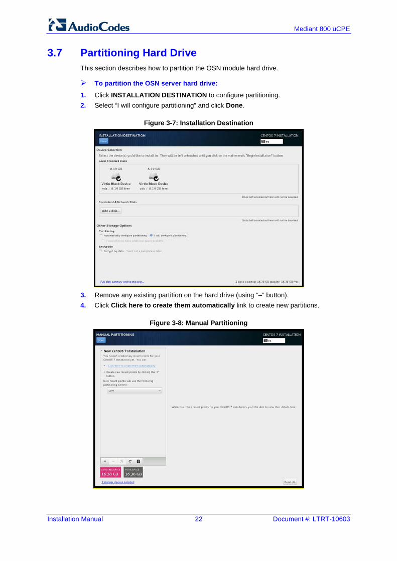
3.7 Partitioning Hard Drive This section describes how to partition the OSN module hard drive.
To partition the OSN server hard drive:
1. Click INSTALLATION DESTINATION to configure partitioning. 2. Select “I will configure partitioning” and click Done.
Figure 3-7: Installation Destination
3. Remove any existing partition on the hard drive (using “–“ button). 4. Click Click here to create them automatically link to create new partitions.
Figure 3-8: Manual Partitioning
Installation Manual 3. Installing Centos 7 on Mediant 800 uCPE’S OSN Module
Version 6.8 23 Mediant 800 uCPE
5. Delete newly created “/home” partition. 6. Change size of “/” partition to a larger value (e.g. 500 MB) – as soon as you switch to
another partition, the installer will automatically adjust the size of “/” partition to maximum available space.
7. Final partitioning scheme should look as follows: a. /boot – 500 MiB b. / – 230 GiB c. swap – 8000 MiB
8. Click Done to apply the new partition scheme.
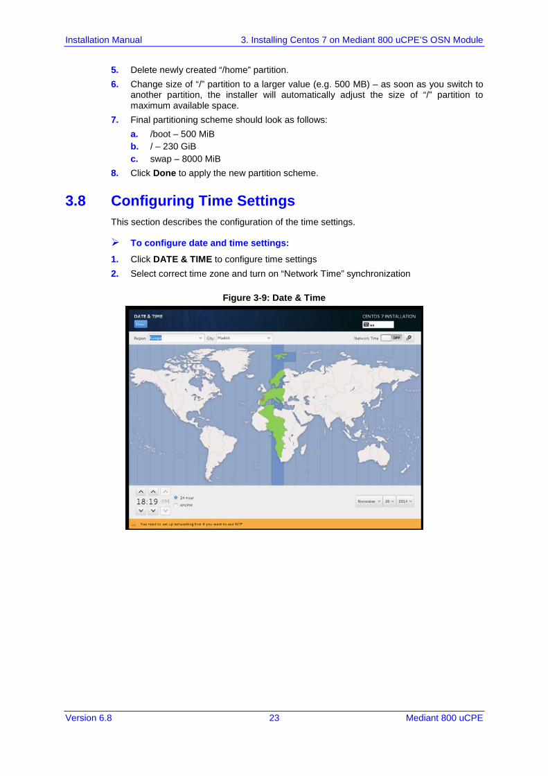
3.8 Configuring Time Settings This section describes the configuration of the time settings.
To configure date and time settings:
1. Click DATE & TIME to configure time settings 2. Select correct time zone and turn on “Network Time” synchronization
Figure 3-9: Date & Time
Installation Manual 24 Document #: LTRT-10603
Mediant 800 uCPE
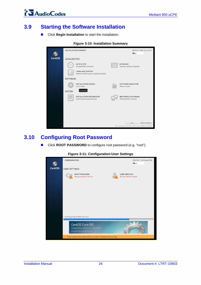
3.9 Starting the Software Installation Click Begin Installation to start the installation.
Figure 3-10: Installation Summary
3.10 Configuring Root Password Click ROOT PASSWORD to configure root password (e.g. “root”).
Figure 3-11: Configuration-User Settings
Installation Manual 3. Installing Centos 7 on Mediant 800 uCPE’S OSN Module
Version 6.8 25 Mediant 800 uCPE
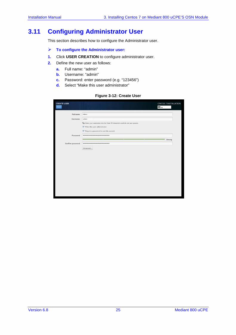
3.11 Configuring Administrator User This section describes how to configure the Administrator user.
To configure the Administrator user:
1. Click USER CREATION to configure administrator user. 2. Define the new user as follows:
a. Full name: “admin” b. Username: “admin” c. Password: enter password (e.g. “123456”) d. Select “Make this user administrator”
Figure 3-12: Create User
Installation Manual 26 Document #: LTRT-10603
Mediant 800 uCPE
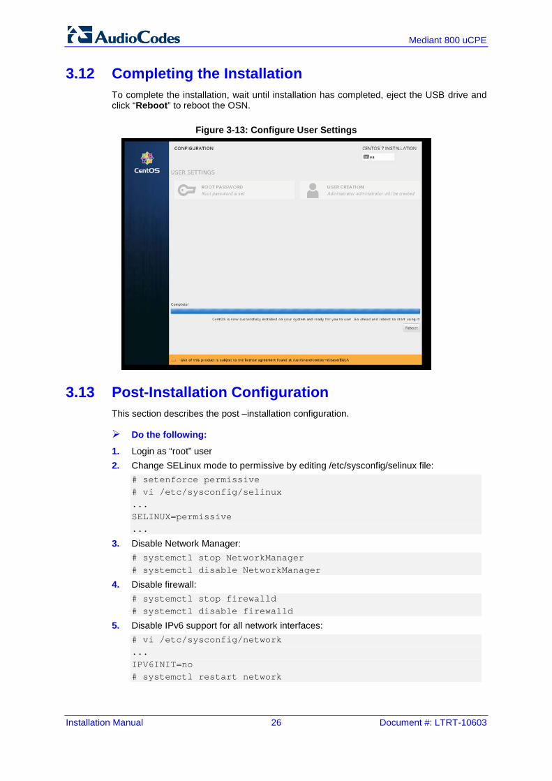
3.12 Completing the Installation To complete the installation, wait until installation has completed, eject the USB drive and click “Reboot” to reboot the OSN.
Figure 3-13: Configure User Settings
3.13 Post-Installation Configuration This section describes the post –installation configuration.
Do the following:
1. Login as “root” user 2. Change SELinux mode to permissive by editing /etc/sysconfig/selinux file:
# setenforce permissive # vi /etc/sysconfig/selinux ... SELINUX=permissive ...
3. Disable Network Manager: # systemctl stop NetworkManager # systemctl disable NetworkManager
4. Disable firewall: # systemctl stop firewalld # systemctl disable firewalld
5. Disable IPv6 support for all network interfaces: # vi /etc/sysconfig/network ... IPV6INIT=no # systemctl restart network
Installation Manual 3. Installing Centos 7 on Mediant 800 uCPE’S OSN Module
Version 6.8 27 Mediant 800 uCPE
6. Add hostname to /etc/hosts file: # vi /etc/hosts … 192.168.0.100 osn
7. Adjust performance profile: # tuned-adm profile virtual-host

Installation Manual 28 Document #: LTRT-10603
Mediant 800 uCPE
This page is intentionally left blank.
Installation Manual 4. Installing Openstack On Mediant 800 uCPE’S OSN Module
Version 6.8 29 Mediant 800 uCPE
4 Installing Openstack On Mediant 800 uCPE’S OSN Module This chapter describes installation of OpenStack RDO Mitaka on Mediant 800 uCPE’s OSN module. More specifically, we will be installing compute node “software suite”.
4.1 Pre-Requisites OpenStack controller node with:
• CentOS 7 • OpenStack RDO Mitaka controller and network node “software suite” Refer to the previous chapter for detailed instructions on how to obtain / install it.
Mediant 800 uCPE • MSBR module with:
♦ Software version 6.8 or later ♦ License key that enables Data Router functionality ♦ Default configuration (if you are not sure about your MSBR module’s
configuration, use “write factory” CLI command to restore default configuration)
• OSN module with: ♦ CentOS 7
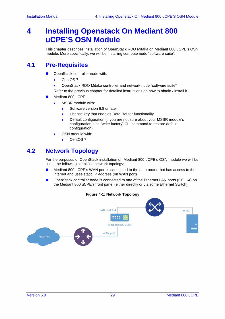
4.2 Network Topology For the purposes of OpenStack installation on Mediant 800 uCPE’s OSN module we will be using the following simplified network topology: Mediant 800 uCPE’s WAN port is connected to the data router that has access to the
internet and uses static IP address (on WAN port) OpenStack controller node is connected to one of the Ethernet LAN ports (GE 1-4) on
the Mediant 800 uCPE’s front panel (either directly or via some Ethernet Switch).
Figure 4-1: Network Topology
Installation Manual 30 Document #: LTRT-10603
Mediant 800 uCPE
If you used default IP addresses for both the OSN module and the OpenStack controller node – they will be able to communicate with one another in such network topology. Verify it using the “ping” command: (on Controller Node) # ping 192.168.0.100 PING 192.168.0.100 (192.168.0.100) 56(84) bytes of data. 64 bytes from 192.168.0.100: icmp_seq=1 ttl=64 time=0.470 ms 64 bytes from 192.168.0.100: icmp_seq=2 ttl=64 time=0.534 ms
The OpenStack installation requires that both OSN module and OpenStack controller node must be able to access the internet. In order to enable such connectivity we will configure static IP address for the Mediant 800 uCPE’s MSBR module’s WAN interface and create a simple routing rule for accessing the internet. Connect to Mediant 800 uCPE’s MSBR module’s CLI interface and run the following commands: enable <password> (e.g. “Admin”) configure data interface GigabitEthernet 0/0 ip address 195.123.123.234 255.255.255.128 # replace IP address and mask with “public” IP address # that may be used for accessing the internet ip name-server 8.8.8.8 exit ip route 0.0.0.0 0.0.0.0 195.123.123.129 GigabitEthernet 0/0 1 # replace IP address with default # gateway in your environment exit write # save current configuration
You should now be able to access the internet from both OSN module and OpenStack controller node. Verify it, for example, by “pinging” Google servers from both machines: # ping google.com PING google.com (216.58.210.14) 56(84) bytes of data. 64 bytes from fra16s07-in-f14.1e100.net (216.58.210.14): icmp_seq=1 ttl=51 time=85.3 ms 64 bytes from lhr08s06-in-f14.1e100.net (216.58.210.14): icmp_seq=2 ttl=51 time=84.7 ms
Installation Manual 4. Installing Openstack On Mediant 800 uCPE’S OSN Module
Version 6.8 31 Mediant 800 uCPE
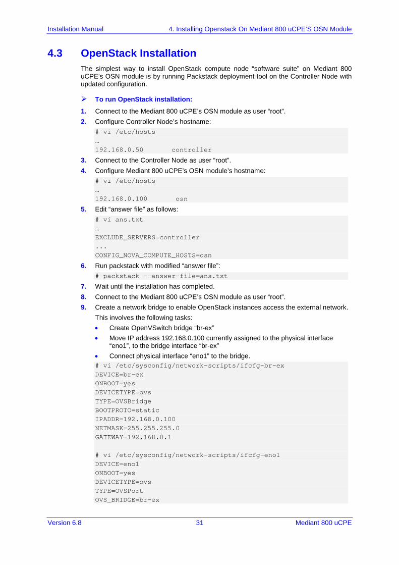
4.3 OpenStack Installation The simplest way to install OpenStack compute node “software suite” on Mediant 800 uCPE’s OSN module is by running Packstack deployment tool on the Controller Node with updated configuration.
To run OpenStack installation:
1. Connect to the Mediant 800 uCPE’s OSN module as user “root”. 2. Configure Controller Node’s hostname:
# vi /etc/hosts … 192.168.0.50 controller
3. Connect to the Controller Node as user “root”. 4. Configure Mediant 800 uCPE’s OSN module’s hostname:
# vi /etc/hosts … 192.168.0.100 osn
5. Edit “answer file” as follows: # vi ans.txt … EXCLUDE_SERVERS=controller ... CONFIG_NOVA_COMPUTE_HOSTS=osn
6. Run packstack with modified “answer file”: # packstack --answer-file=ans.txt
7. Wait until the installation has completed. 8. Connect to the Mediant 800 uCPE’s OSN module as user “root”. 9. Create a network bridge to enable OpenStack instances access the external network.
This involves the following tasks: • Create OpenVSwitch bridge “br-ex” • Move IP address 192.168.0.100 currently assigned to the physical interface
“eno1”, to the bridge interface “br-ex” • Connect physical interface “eno1” to the bridge. # vi /etc/sysconfig/network-scripts/ifcfg-br-ex DEVICE=br-ex ONBOOT=yes DEVICETYPE=ovs TYPE=OVSBridge BOOTPROTO=static IPADDR=192.168.0.100 NETMASK=255.255.255.0 GATEWAY=192.168.0.1 # vi /etc/sysconfig/network-scripts/ifcfg-eno1 DEVICE=eno1 ONBOOT=yes DEVICETYPE=ovs TYPE=OVSPort OVS_BRIDGE=br-ex
Installation Manual 32 Document #: LTRT-10603
Mediant 800 uCPE
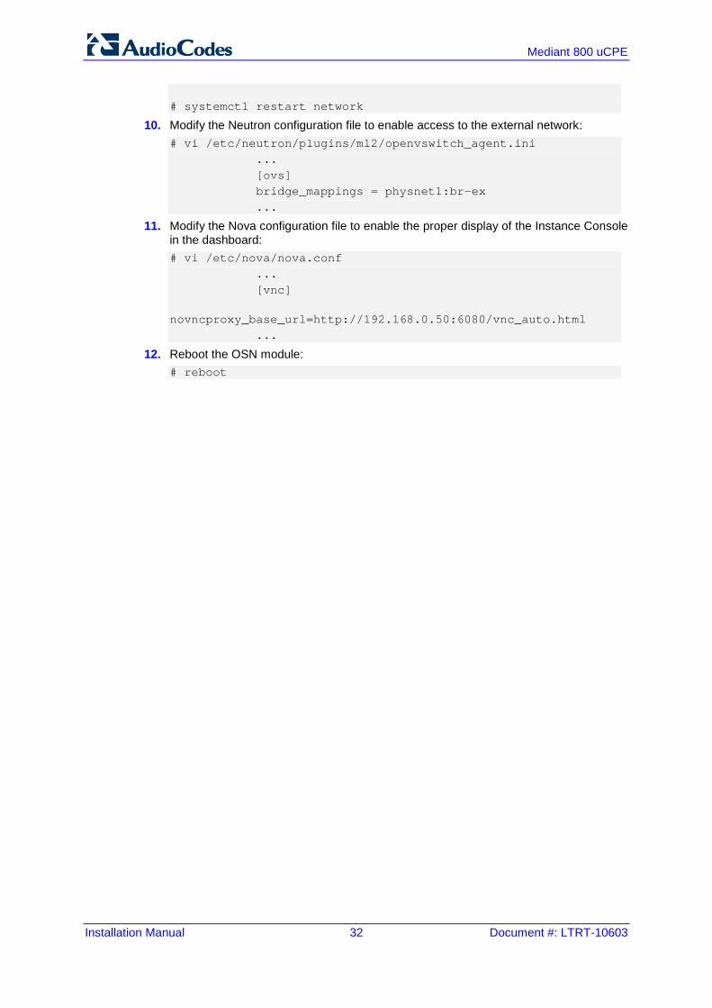
# systemctl restart network
10. Modify the Neutron configuration file to enable access to the external network: # vi /etc/neutron/plugins/ml2/openvswitch_agent.ini ... [ovs] bridge_mappings = physnet1:br-ex ...
11. Modify the Nova configuration file to enable the proper display of the Instance Console in the dashboard: # vi /etc/nova/nova.conf ... [vnc] novncproxy_base_url=http://192.168.0.50:6080/vnc_auto.html ...
12. Reboot the OSN module: # reboot
Installation Manual 5. Installing Pre-Built Openstack Image Mediant 800 uCPE’S OSN Module
Version 6.8 33 Mediant 800 uCPE
5 Installing Pre-Built Openstack Image Mediant 800 uCPE’S OSN Module
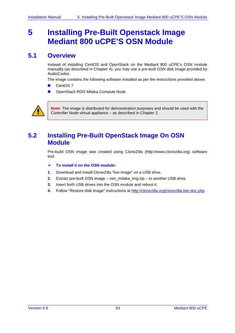
5.1 Overview Instead of installing CentOS and OpenStack on the Mediant 800 uCPE’s OSN module manually (as described in Chapter 4), you may use a pre-built OSN disk image provided by AudioCodes. The image contains the following software installed as per the instructions provided above: CentOS 7 OpenStack RDO Mitaka Compute Node
Note: The image is distributed for demonstration purposes and should be used with the Controller Node virtual appliance – as described in Chapter 2.
5.2 Installing Pre-Built OpenStack Image On OSN Module Pre-build OSN image was created using CloneZilla (http://www.clonezilla.org) software tool.
To install it on the OSN module:
1. Download and install CloneZilla “live image” on a USB drive. 2. Extract pre-built OSN image – osn_mitaka_img.zip – to another USB drive. 3. Insert both USB drives into the OSN module and reboot it. 4. Follow “Restore disk image” instructions at http://clonezilla.org/clonezilla-live-doc.php.

Installation Manual 34 Document #: LTRT-10603
Mediant 800 uCPE
This page is intentionally left blank.
Installation Manual 6. Configuring Mediant 800 uCPE’S MSBR Module
Version 6.8 35 Mediant 800 uCPE
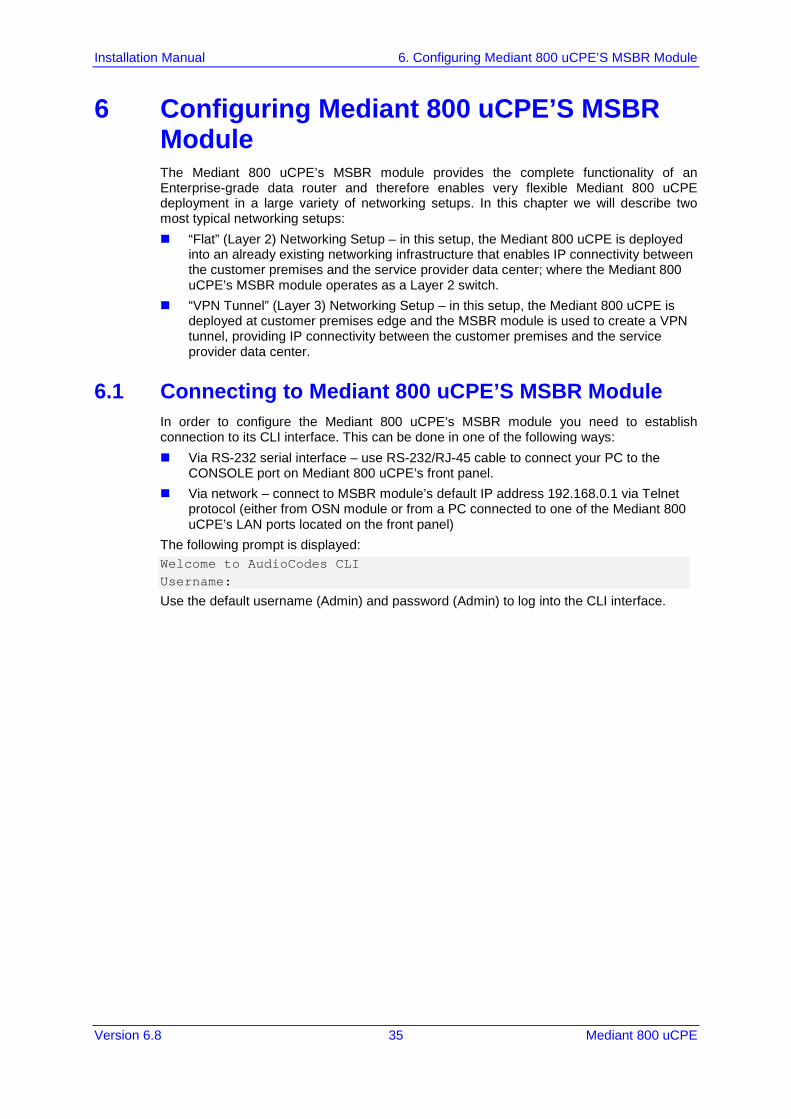
6 Configuring Mediant 800 uCPE’S MSBR Module The Mediant 800 uCPE’s MSBR module provides the complete functionality of an Enterprise-grade data router and therefore enables very flexible Mediant 800 uCPE deployment in a large variety of networking setups. In this chapter we will describe two most typical networking setups: “Flat” (Layer 2) Networking Setup – in this setup, the Mediant 800 uCPE is deployed
into an already existing networking infrastructure that enables IP connectivity between the customer premises and the service provider data center; where the Mediant 800 uCPE’s MSBR module operates as a Layer 2 switch.
“VPN Tunnel” (Layer 3) Networking Setup – in this setup, the Mediant 800 uCPE is deployed at customer premises edge and the MSBR module is used to create a VPN tunnel, providing IP connectivity between the customer premises and the service provider data center.
6.1 Connecting to Mediant 800 uCPE’S MSBR Module In order to configure the Mediant 800 uCPE’s MSBR module you need to establish connection to its CLI interface. This can be done in one of the following ways: Via RS-232 serial interface – use RS-232/RJ-45 cable to connect your PC to the
CONSOLE port on Mediant 800 uCPE’s front panel. Via network – connect to MSBR module’s default IP address 192.168.0.1 via Telnet
protocol (either from OSN module or from a PC connected to one of the Mediant 800 uCPE’s LAN ports located on the front panel)
The following prompt is displayed: Welcome to AudioCodes CLI Username:
Use the default username (Admin) and password (Admin) to log into the CLI interface.

Installation Manual 36 Document #: LTRT-10603
Mediant 800 uCPE
6.2 “Flat” (Layer 2) Networking Setup The “Flat” (Layer 2) networking setup is applicable in cases where the Mediant 800 uCPE is deployed in the customer premises that already have proper networking infrastructure that enables IP connectivity between the customer site and the service provider’s data center. The following diagram shows such a use-case and the relevant Mediant 800 uCPE configuration.
Figure 6-1: “Flat” (Layer 2) Networking Setup
The Mediant 800 uCPE’s MSBR module is used as Layer 2 switch. Three VLAN’s are created: VLAN 100 – used for connecting the OSN module with the OpenStack platform
running in the cloud (called “management network” in OpenStack terms); first Gigabit Ethernet LAN port (GE_1) on Mediant 800 uCPE’s front panel should be used for connecting Mediant 800 uCPE to the “management network” (VLAN 100 is “native VLAN” for this port)
VLAN 200 – used for connecting with the equipment deployed in service provider’s datacenter (we call this “datacenter network”); second Gigabit Ethernet LAN port (GE_2) on Mediant 800 uCPE’s front panel should be used for connecting Mediant 800 uCPE to the “datacenter network” (VLAN 200 is “native VLAN” for this port).
VLAN 300 – used for connecting with the equipment deployed in customer premises (we call this “local site network”); third Gigabit Ethernet LAN port (GE_3) on Mediant 800 uCPE’s front panel should be used for connecting the Mediant 800 uCPE to the “local site network” (VLAN 300 is “native VLAN” for this port).
Installation Manual 6. Configuring Mediant 800 uCPE’S MSBR Module
Version 6.8 37 Mediant 800 uCPE
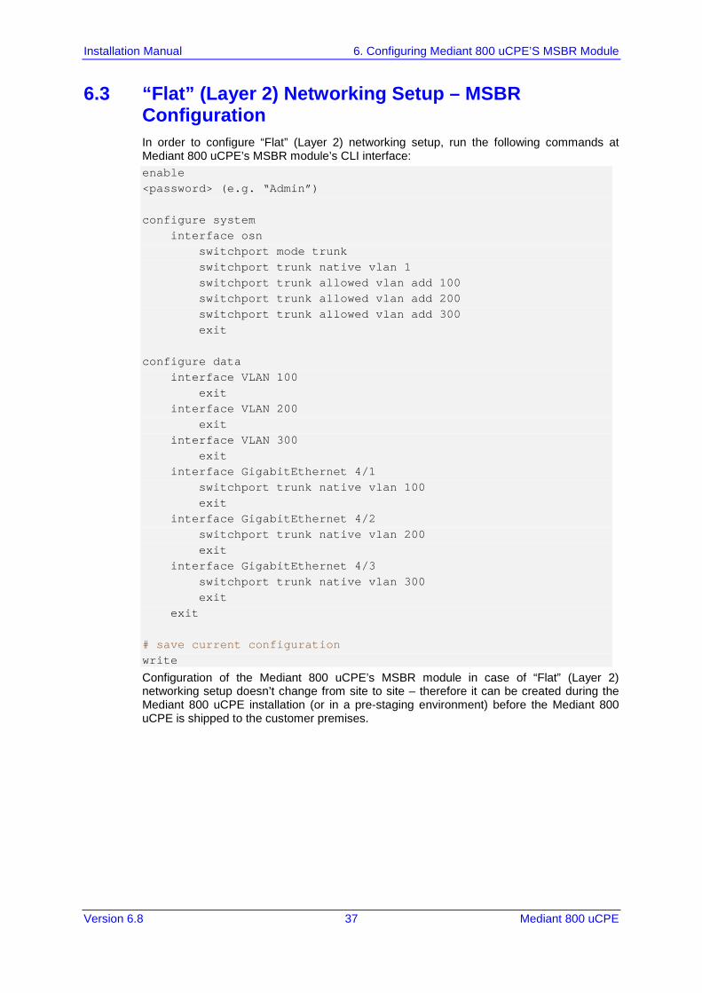
6.3 “Flat” (Layer 2) Networking Setup – MSBR Configuration In order to configure “Flat” (Layer 2) networking setup, run the following commands at Mediant 800 uCPE’s MSBR module’s CLI interface: enable <password> (e.g. “Admin”) configure system interface osn switchport mode trunk switchport trunk native vlan 1 switchport trunk allowed vlan add 100 switchport trunk allowed vlan add 200 switchport trunk allowed vlan add 300 exit configure data interface VLAN 100 exit interface VLAN 200 exit interface VLAN 300 exit interface GigabitEthernet 4/1 switchport trunk native vlan 100 exit interface GigabitEthernet 4/2 switchport trunk native vlan 200 exit interface GigabitEthernet 4/3 switchport trunk native vlan 300 exit exit # save current configuration write
Configuration of the Mediant 800 uCPE’s MSBR module in case of “Flat” (Layer 2) networking setup doesn’t change from site to site – therefore it can be created during the Mediant 800 uCPE installation (or in a pre-staging environment) before the Mediant 800 uCPE is shipped to the customer premises.
Installation Manual 38 Document #: LTRT-10603
Mediant 800 uCPE
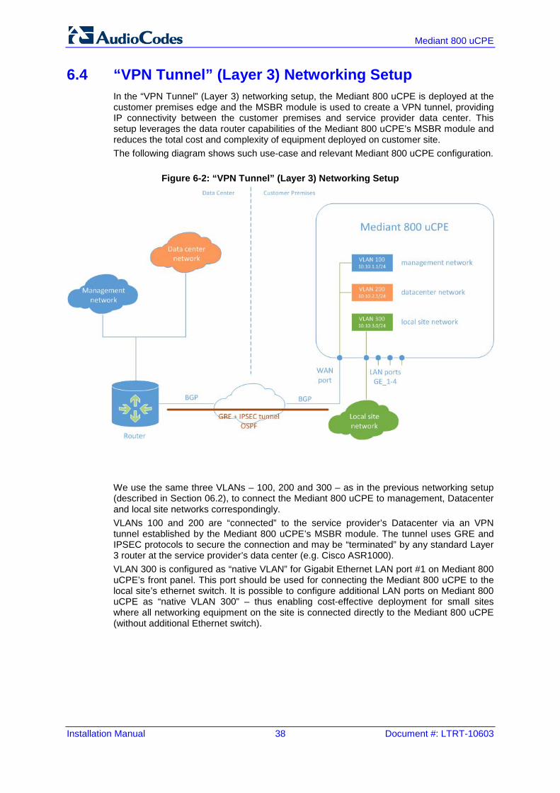
6.4 “VPN Tunnel” (Layer 3) Networking Setup In the “VPN Tunnel” (Layer 3) networking setup, the Mediant 800 uCPE is deployed at the customer premises edge and the MSBR module is used to create a VPN tunnel, providing IP connectivity between the customer premises and service provider data center. This setup leverages the data router capabilities of the Mediant 800 uCPE’s MSBR module and reduces the total cost and complexity of equipment deployed on customer site. The following diagram shows such use-case and relevant Mediant 800 uCPE configuration.
Figure 6-2: “VPN Tunnel” (Layer 3) Networking Setup
We use the same three VLANs – 100, 200 and 300 – as in the previous networking setup (described in Section 0 6.2), to connect the Mediant 800 uCPE to management, Datacenter and local site networks correspondingly. VLANs 100 and 200 are “connected” to the service provider’s Datacenter via an VPN tunnel established by the Mediant 800 uCPE’s MSBR module. The tunnel uses GRE and IPSEC protocols to secure the connection and may be “terminated” by any standard Layer 3 router at the service provider’s data center (e.g. Cisco ASR1000). VLAN 300 is configured as “native VLAN” for Gigabit Ethernet LAN port #1 on Mediant 800 uCPE’s front panel. This port should be used for connecting the Mediant 800 uCPE to the local site’s ethernet switch. It is possible to configure additional LAN ports on Mediant 800 uCPE as “native VLAN 300” – thus enabling cost-effective deployment for small sites where all networking equipment on the site is connected directly to the Mediant 800 uCPE (without additional Ethernet switch).
Installation Manual 6. Configuring Mediant 800 uCPE’S MSBR Module
Version 6.8 39 Mediant 800 uCPE
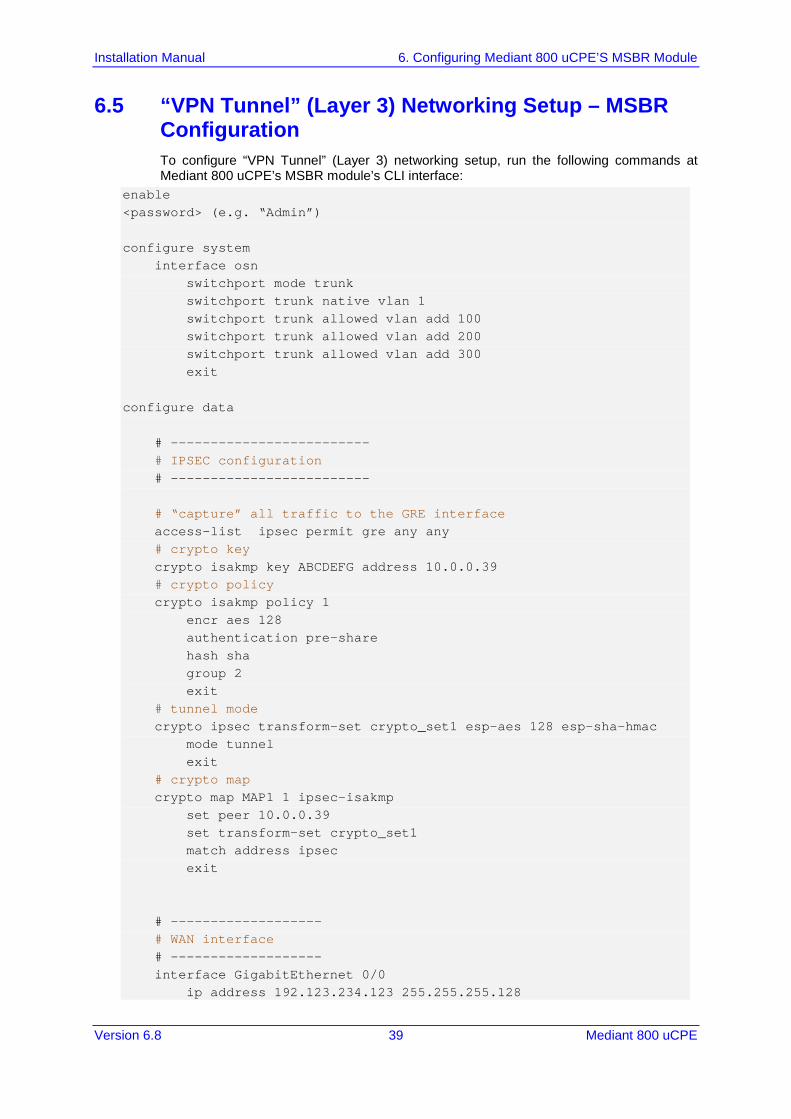
6.5 “VPN Tunnel” (Layer 3) Networking Setup – MSBR Configuration To configure “VPN Tunnel” (Layer 3) networking setup, run the following commands at Mediant 800 uCPE’s MSBR module’s CLI interface:
enable <password> (e.g. “Admin”) configure system interface osn switchport mode trunk switchport trunk native vlan 1 switchport trunk allowed vlan add 100 switchport trunk allowed vlan add 200 switchport trunk allowed vlan add 300 exit configure data # ------------------------- # IPSEC configuration # ------------------------- # “capture” all traffic to the GRE interface access-list ipsec permit gre any any # crypto key crypto isakmp key ABCDEFG address 10.0.0.39 # crypto policy crypto isakmp policy 1 encr aes 128 authentication pre-share hash sha group 2 exit # tunnel mode crypto ipsec transform-set crypto_set1 esp-aes 128 esp-sha-hmac mode tunnel exit # crypto map crypto map MAP1 1 ipsec-isakmp set peer 10.0.0.39 set transform-set crypto_set1 match address ipsec exit # ------------------- # WAN interface # ------------------- interface GigabitEthernet 0/0 ip address 192.123.234.123 255.255.255.128

Installation Manual 40 Document #: LTRT-10603
Mediant 800 uCPE
ip name-server 8.8.8.8 crypto map MAP1 exit # --------------------- # Tunnel interface # --------------------- interface GRE 1 ip address 1.1.1.34 255.255.255.0 mtu 1400 no napt tunnel source GigabitEthernet 0/0 tunnel destination 10.0.0.39 ip ospf hello-interval 1 ip ospf dead-interval 4 exit # ------------------- # LAN interfaces # ------------------- interface VLAN 100 ip address 10.10.1.1 255.255.255.0 exit interface VLAN 200 ip address 10.10.2.1 255.255.255.0 exit interface VLAN 300 exit interface GigabitEthernet 4/1 switchport trunk native vlan 300 exit # ------------------- # Routing protocol # ------------------- router bgp 34 bgp router-id 10.0.0.34 network 10.0.0.0/24 neighbor 10.0.0.39 remote-as 39 exit router ospf network 1.1.1.0/24 area 0.0.0.0 network 10.10.1.0/24 area 0.0.0.100 network 10.10.2.0/24 area 0.0.0.200 exit exit # save current configuration write
Installation Manual 7. Configuring Management Interface on OSN Module
Version 6.8 41 Mediant 800 uCPE
7 Configuring Management Interface on OSN Module
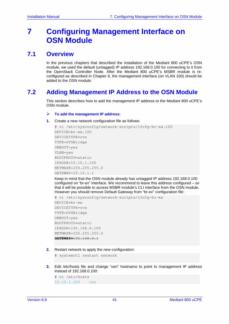
7.1 Overview In the previous chapters that described the installation of the Mediant 800 uCPE’s OSN module, we used the default (untagged) IP address 192.168.0.100 for connecting to it from the OpenStack Controller Node. After the Mediant 800 uCPE’s MSBR module is re-configured as described in Chapter 6, the management interface (on VLAN 100) should be added to the OSN module.
7.2 Adding Management IP Address to the OSN Module This section describes how to add the management IP address to the Mediant 800 uCPE’s OSN module.
To add the management IP address:
1. Create a new network configuration file as follows: # vi /etc/sysconfig/network-scripts/ifcfg-br-ex.100 DEVICE=br-ex.100 DEVICETYPE=ovs TYPE=OVSBridge ONBOOT=yes VLAN=yes BOOTPROTO=static IPADDR=10.10.1.100 NETMASK=255.255.255.0 GATEWAY=10.10.1.1
Keep in mind that the OSN module already has untagged IP address 192.168.0.100 configured on “br-ex” interface. We recommend to leave this address configured – so that it will be possible to access MSBR module’s CLI interface from the OSN module. However you should remove Default Gateway from “br-ex” configuration file: # vi /etc/sysconfig/network-scripts/ifcfg-br-ex DEVICE=br-ex DEVICETYPE=ovs TYPE=OVSBridge ONBOOT=yes BOOTPROTO=static IPADDR=192.168.0.100 NETMASK=255.255.255.0 GATEWAY=192.168.0.1
2. Restart network to apply the new configuration: # systemctl restart network
3. Edit /etc/hosts file and change “osn” hostname to point to management IP address instead of 192.168.0.100: # vi /etc/hosts 10.10.1.100 osn

Installation Manual 42 Document #: LTRT-10603
Mediant 800 uCPE
This page is intentionally left blank.
Installation Manual 8. Configuring OpenStack Networks
Version 6.8 43 Mediant 800 uCPE
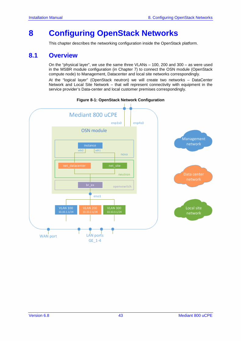
8 Configuring OpenStack Networks This chapter describes the networking configuration inside the OpenStack platform.
8.1 Overview On the “physical layer”, we use the same three VLANs – 100, 200 and 300 – as were used in the MSBR module configuration (in Chapter 7) to connect the OSN module (OpenStack compute node) to Management, Datacenter and local site networks correspondingly. At the “logical layer” (OpenStack neutron) we will create two networks – DataCenter Network and Local Site Network – that will represent connectivity with equipment in the service provider’s Data-center and local customer premises correspondingly.
Figure 8-1: OpenStack Network Configuration

Installation Manual 44 Document #: LTRT-10603
Mediant 800 uCPE
8.2 Neutron Configuration OpenStack network subsystem (neutron) supports multiple types of tenant networks: Overlayed networks (GRE and VXLAN) – use GRE and VXLAN encapsulation
protocols to create overlay networks to activate and control communication between compute instances. Networking router is required to allow traffic to flow outside of the GRE or VXLAN tenant network. A router is also required to connect directly-connected tenant networks with external networks, including the Internet. The router provides the ability to connect to instances directly from an external network using floating IP addresses.
Flat networks – all instances reside on the same network, which can also be shared with the hosts. No VLAN tagging or other network segregation takes place.
VLAN networks – use VLAN IDs (802.1Q tagged) to create multiple provider or tenant networks. Instances may communicate with each other across the environment. They can also communicate with dedicated servers, firewalls, load balancers, and other networking infrastructure on the same layer 2 VLAN.
Since we wish to enable direct connectivity between OpenStack instances (VNFs) and networking infrastructure located in the customer premises, we will use “VLAN” provider networks.
To configure the OpenStack network subsystem:
1. Connect to the OpenStack Controller Node as user “root” 2. Activate OpenStack CLI environment:
# . keystonerc_admin
3. Create “Data Center” provider network: # neutron net-create net_datacenter --shared --provider:network_type vlan \ --provider:physical_network physnet1 --provider:segmentation_id=200 # neutron subnet-create --name subnet_datacenter --gateway 10.10.2.1 \ --dns-nameserver 10.10.2.1 --allocation-pool start=10.10.2.224,end=10.10.2.254 \ net_datacenter 10.10.2.0/24
4. Create “Local Site” provider network: # neutron net-create net_site --shared --provider:network_type vlan \ --provider:physical_network physnet1 --provider:segmentation_id=300 # neutron subnet-create --name subnet_site --gateway 10.10.3.1 \ --dns-nameserver 10.10.3.1 --allocation-pool start=10.10.3.224,end=10.10.3.254 \ net_site 10.10.3.0/24
Installation Manual 9. Re-configuring IP Addresses
Version 6.8 45 Mediant 800 uCPE
9 Re-configuring IP Addresses 9.1 Overview
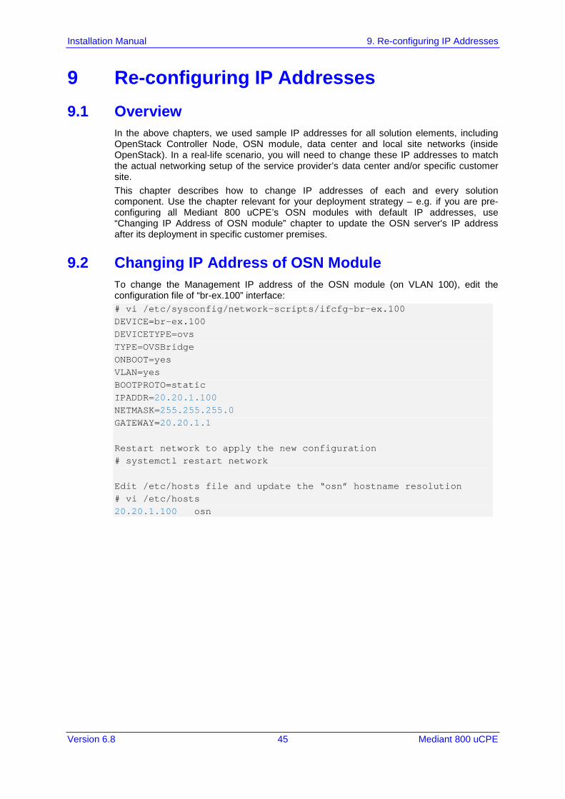
In the above chapters, we used sample IP addresses for all solution elements, including OpenStack Controller Node, OSN module, data center and local site networks (inside OpenStack). In a real-life scenario, you will need to change these IP addresses to match the actual networking setup of the service provider’s data center and/or specific customer site. This chapter describes how to change IP addresses of each and every solution component. Use the chapter relevant for your deployment strategy – e.g. if you are pre-configuring all Mediant 800 uCPE’s OSN modules with default IP addresses, use “Changing IP Address of OSN module” chapter to update the OSN server's IP address after its deployment in specific customer premises.
9.2 Changing IP Address of OSN Module To change the Management IP address of the OSN module (on VLAN 100), edit the configuration file of “br-ex.100” interface: # vi /etc/sysconfig/network-scripts/ifcfg-br-ex.100 DEVICE=br-ex.100 DEVICETYPE=ovs TYPE=OVSBridge ONBOOT=yes VLAN=yes BOOTPROTO=static IPADDR=20.20.1.100 NETMASK=255.255.255.0 GATEWAY=20.20.1.1 Restart network to apply the new configuration # systemctl restart network Edit /etc/hosts file and update the “osn” hostname resolution # vi /etc/hosts 20.20.1.100 osn
Installation Manual 46 Document #: LTRT-10603
Mediant 800 uCPE
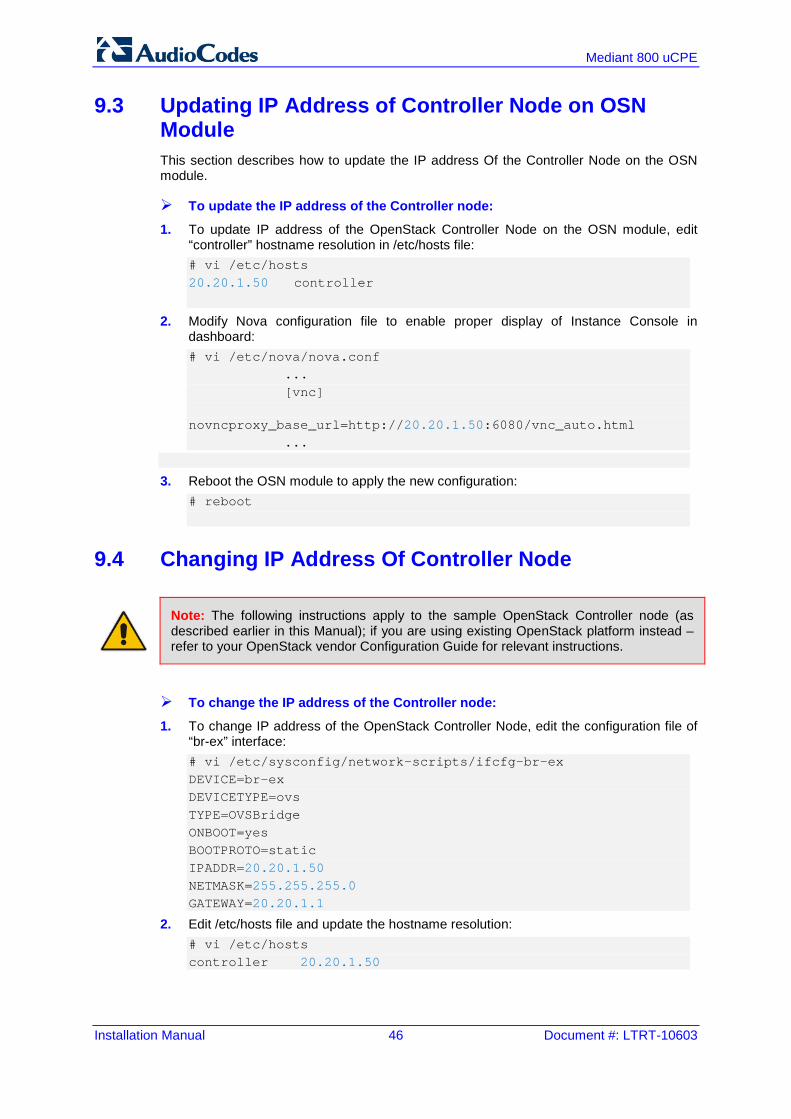
9.3 Updating IP Address of Controller Node on OSN Module This section describes how to update the IP address Of the Controller Node on the OSN module.
To update the IP address of the Controller node:
1. To update IP address of the OpenStack Controller Node on the OSN module, edit “controller” hostname resolution in /etc/hosts file: # vi /etc/hosts 20.20.1.50 controller
2. Modify Nova configuration file to enable proper display of Instance Console in dashboard: # vi /etc/nova/nova.conf ... [vnc] novncproxy_base_url=http://20.20.1.50:6080/vnc_auto.html ...
3. Reboot the OSN module to apply the new configuration: # reboot
9.4 Changing IP Address Of Controller Node
Note: The following instructions apply to the sample OpenStack Controller node (as described earlier in this Manual); if you are using existing OpenStack platform instead – refer to your OpenStack vendor Configuration Guide for relevant instructions.
To change the IP address of the Controller node:
1. To change IP address of the OpenStack Controller Node, edit the configuration file of “br-ex” interface: # vi /etc/sysconfig/network-scripts/ifcfg-br-ex DEVICE=br-ex DEVICETYPE=ovs TYPE=OVSBridge ONBOOT=yes BOOTPROTO=static IPADDR=20.20.1.50 NETMASK=255.255.255.0 GATEWAY=20.20.1.1
2. Edit /etc/hosts file and update the hostname resolution: # vi /etc/hosts controller 20.20.1.50
Installation Manual 9. Re-configuring IP Addresses
Version 6.8 47 Mediant 800 uCPE
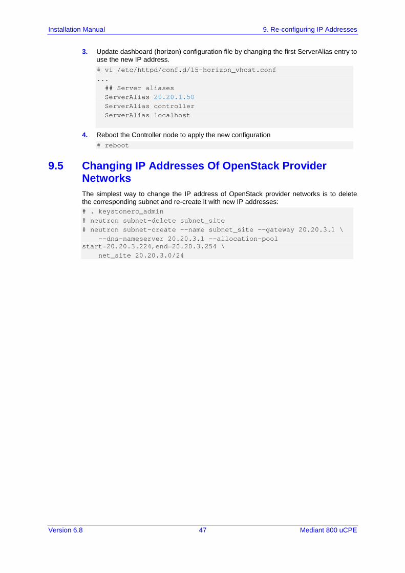
3. Update dashboard (horizon) configuration file by changing the first ServerAlias entry to use the new IP address. # vi /etc/httpd/conf.d/15-horizon_vhost.conf ... ## Server aliases ServerAlias 20.20.1.50 ServerAlias controller ServerAlias localhost
4. Reboot the Controller node to apply the new configuration # reboot
9.5 Changing IP Addresses Of OpenStack Provider Networks The simplest way to change the IP address of OpenStack provider networks is to delete the corresponding subnet and re-create it with new IP addresses: # . keystonerc_admin # neutron subnet-delete subnet_site # neutron subnet-create --name subnet_site --gateway 20.20.3.1 \ --dns-nameserver 20.20.3.1 --allocation-pool start=20.20.3.224,end=20.20.3.254 \ net_site 20.20.3.0/24

International Headquarters
Contact us: www.audiocodes.com/info Website: www.audiocodes.com Document #: LTRT-10603