medical video coding based on 2nd-generation wavelets
TRANSCRIPT

electronics
Article
Medical Video Coding Based on 2nd-GenerationWavelets: Performance Evaluation
Merzak Ferroukhi 1, Abdeldjalil Ouahabi 2,3,* , Mokhtar Attari 1, Yassine Habchi 4 andAbdelmalik Taleb-Ahmed 5
1 Laboratory of Instrumentation, Faculty of Electronics and Computers, University of Sciences andTechnology Houari Boumediene, 16111 Algiers, Algeria; [email protected] (M.F.);[email protected] (M.A.)
2 Polytech Tours, Imaging and Brain, INSERM U930, University of Tours, 37200 Tours, France3 Computer Science Department, LIMPAF, University of Bouira, 10000 Bouira, Algeria4 Electrical Engineering Department, LTIT, Bechar University, 08000 Bechar, Algeria; [email protected] IEMN DOAE UMR CNRS 8520, UPHF, 59313 Valenciennes, France;
[email protected]* Correspondence: [email protected]; Tel.: +33-603894463
Received: 5 October 2018; Accepted: 8 January 2019; Published: 14 January 2019
Abstract: The operations of digitization, transmission and storage of medical data, particularlyimages, require increasingly effective encoding methods not only in terms of compression ratioand flow of information but also in terms of visual quality. At first, there was DCT (discrete cosinetransform) then DWT (discrete wavelet transform) and their associated standards in terms of codingand image compression. The 2nd-generation wavelets seeks to be positioned and confronted bythe image and video coding methods currently used. It is in this context that we suggest a methodcombining bandelets and the SPIHT (set partitioning in hierarchical trees) algorithm. There are twomain reasons for our approach: the first lies in the nature of the bandelet transform to take advantageof capturing the geometrical complexity of the image structure. The second reason is the suitability ofencoding the bandelet coefficients by the SPIHT encoder. Quality measurements indicate that in somecases (for low bit rates) the performance of the proposed coding competes with the well-establishedones (H.264 or MPEG4 AVC and H.265 or MPEG4 HEVC) and opens up new application prospects inthe field of medical imaging.
Keywords: bandelets; medical imaging; quadtree decomposition; SPIHT coder; video coding; MPEG4AVC; HEVC; video quality measure
1. Introduction and Motivation
The extensive volume of patient medical data recorded at every moment in hospitals, medicalimaging centers and other medical organizations has become a major issue. The need for quasi-infinitestorage space and efficient real-time transmission in specific applications such as medical imaging,military imaging and satellite imaging requires advanced techniques and technologies including codingmethods to reduce the amount of data to be stored or transmitted. Without coding of information, it isvery difficult and sometimes impossible to make a way to store or communicate big data (large volumesof high velocity and complex images, audio and video information) via the internet. The encoding ofthese data is obtained by eliminating the redundant or unnecessary information in the original framewhich cannot be identified with the naked eye.
Telemedicine offers valuable specialty diagnostic services to underserved patients in rural areas,but often requires significant image compression to transmit medical images using limited bandwidth
Electronics 2019, 8, 88; doi:10.3390/electronics8010088 www.mdpi.com/journal/electronics

Electronics 2019, 8, 88 2 of 18
networks. The difficulty is that compressing images such as those for tele-echography can introduceartifacts and reduce medical image quality which affects directly the diagnosis [1].
This possible disadvantage is inherent in all lossy compression methods.Figure 1 recalls the key steps of video coding. Transformation is a linear and reversible operation
that allows the image to be represented in the transform domain where the useful informationis well localized. This property will make it possible during the compression to achieve gooddiscrimination, that is to say the suppression of unnecessary or redundant information. The discretecosine transform and the wavelet transform are among the most popular transforms proposed forimage and video coding.
Electronics 2019, 8, x FOR PEER REVIEW 2 of 18
bandwidth networks. The difficulty is that compressing images such as those for tele-echography can introduce artifacts and reduce medical image quality which affects directly the diagnosis [1].
This possible disadvantage is inherent in all lossy compression methods. Figure 1 recalls the key steps of video coding. Transformation is a linear and reversible
operation that allows the image to be represented in the transform domain where the useful information is well localized. This property will make it possible during the compression to achieve good discrimination, that is to say the suppression of unnecessary or redundant information. The discrete cosine transform and the wavelet transform are among the most popular transforms proposed for image and video coding.
Quantization is the step of the compression process during which a large part of the elimination of unnecessary or redundant information occurs.
Coding techniques e.g., Huffman coding and arithmetic coding [2], are the best-known entropy coding particularly in image and video coding.
Figure 1. Simplified video coding scheme.
It is well known that lossless compression methods have the advantage of providing an image without any loss of quality and the disadvantage of compressing weakly. Hence, this type of compression is not suitable for transmission or storage of big data such as video. Conversely, lossy compression produces significantly smaller file sizes often at the expense of image quality. However, lossy coding based on transforms has gained great importance when several applications have appeared. In particular, lossy coding represents an acceptable option for coding medical images. e.g., a DICOM (Digital Imaging Communication in Medicine) JPEG (Joint Photographic Experts Group) based on discrete cosine transform (DCT) and a DICOM JPEG 2000 based on wavelet. In this context, wavelet-based image coding, e.g., JPEG2000, using multiresolution analysis [3,4] exhibits performance that is highly superior to other methods such as those based on DCT, e.g., JPEG.
In 1993, Shapiro introduced a lossy image compression algorithm that he called embedded zerotrees of wavelet (EZW) [5]. The success of coding wavelet approaches is largely due to the occurrence of effective sub-band coders. The EZW encoder is the first to provide remarkable distortion-rate performance while allowing progressive decoding of the image. The principle of zerotrees, or other partitioning structures in sets of zeros, makes it possible to take account of the residual dependence of the coefficients between them. More precisely, since the high-energy coefficients are spatially grouped, their position is effectively computed by indicating the position of the sets of low-energy coefficients. After separation of the low-energy coefficients and the energetic coefficients, the latter is relatively independent and can be efficiently coded using quantification and entropy coding techniques.
In 1996, Said and Pearlman proposed a hierarchical tree partitioning coding scheme called set partitioning in hierarchical tree (SPIHT) [6], based on the same basic EZW, and exhibiting better performance than the original EZW.
Video compression algorithms such as H.264 and MPEG use inter-frame prediction to reduce video data between a series of images. This involves techniques such as differential coding where an
Figure 1. Simplified video coding scheme.
Quantization is the step of the compression process during which a large part of the eliminationof unnecessary or redundant information occurs.
Coding techniques e.g., Huffman coding and arithmetic coding [2], are the best-known entropycoding particularly in image and video coding.
It is well known that lossless compression methods have the advantage of providing an imagewithout any loss of quality and the disadvantage of compressing weakly. Hence, this type ofcompression is not suitable for transmission or storage of big data such as video. Conversely,lossy compression produces significantly smaller file sizes often at the expense of image quality.However, lossy coding based on transforms has gained great importance when several applicationshave appeared. In particular, lossy coding represents an acceptable option for coding medical images.e.g., a DICOM (Digital Imaging Communication in Medicine) JPEG (Joint Photographic Experts Group)based on discrete cosine transform (DCT) and a DICOM JPEG 2000 based on wavelet. In this context,wavelet-based image coding, e.g., JPEG2000, using multiresolution analysis [3,4] exhibits performancethat is highly superior to other methods such as those based on DCT, e.g., JPEG.
In 1993, Shapiro introduced a lossy image compression algorithm that he called embeddedzerotrees of wavelet (EZW) [5]. The success of coding wavelet approaches is largely due to theoccurrence of effective sub-band coders. The EZW encoder is the first to provide remarkabledistortion-rate performance while allowing progressive decoding of the image. The principle ofzerotrees, or other partitioning structures in sets of zeros, makes it possible to take account of theresidual dependence of the coefficients between them. More precisely, since the high-energy coefficientsare spatially grouped, their position is effectively computed by indicating the position of the sets oflow-energy coefficients. After separation of the low-energy coefficients and the energetic coefficients,the latter is relatively independent and can be efficiently coded using quantification and entropycoding techniques.
In 1996, Said and Pearlman proposed a hierarchical tree partitioning coding scheme called setpartitioning in hierarchical tree (SPIHT) [6], based on the same basic EZW, and exhibiting betterperformance than the original EZW.
Video compression algorithms such as H.264 and MPEG use inter-frame prediction to reducevideo data between a series of images. This involves techniques such as differential coding where an

Electronics 2019, 8, 88 3 of 18
image is compared with a reference image and only the pixels that have changed with respect to thatreference image are coded.
MPEG (Moving Picture Experts Group) allows to encode video using three coding modes:Intra coded frames (I): frames are coded separately without reference to previous images (i.e., as
JPEG coding).Predictive coded frames (P): images are described by difference from previous images.Bidirectionally predictive coded frames (B): the images are described by difference with the
previous image and the following image.In order to optimize MPEG coding, the image sequences are in practice coded in a series of I, B,
and P images, the order of which has been determined experimentally. The typical sequence calledGOP (group of pictures) is as follows (see Figure 2):
Electronics 2019, 8, x FOR PEER REVIEW 3 of 18
image is compared with a reference image and only the pixels that have changed with respect to that reference image are coded.
MPEG (Moving Picture Experts Group) allows to encode video using three coding modes: Intra coded frames (I): frames are coded separately without reference to previous images (i.e.,
as JPEG coding). Predictive coded frames (P): images are described by difference from previous images. Bidirectionally predictive coded frames (B): the images are described by difference with the
previous image and the following image. In order to optimize MPEG coding, the image sequences are in practice coded in a series of I, B,
and P images, the order of which has been determined experimentally. The typical sequence called GOP (group of pictures) is as follows (see Figure 2):
Figure 2. Typical sequence with I, B and P frames. P frame can only refer to the previous I or P frames, while a B frame can refer to previous or subsequent I or P frames.
To evaluate the visual quality of the reconstructed video, several measurements of the quality of the MPEG video are validated in [7,8].
As a successor to the famous H.264 or MPEG-4 Part 10 standards [9,10], HEVC (High-Efficiency Video Coding) or H.265 standard has recently been defined as a promising standard for video coding, In June 2013 [11], the first version of HEVC was announced, and to improve the efficiency of the coding of this standard, a set of its components requires more development. In addition, this new system requires new hardware and software investments delaying its adoption in applications such as in the medical field.
In our case, the use of wavelets enhances the contours, which minimizes the impact of information loss in medical imaging, mainly in tumor detection [12–15]. Moreover, bandelets are 2nd-generation wavelets and the corresponding transform is an orthogonal multi-resolution transform that is able to capture the geometric content of images and surfaces. Hence, the possible presence of artifacts will be considerably reduced.
Our motivation lies in the prospect of offering a new codec that is simple to implement with performances superior to the current H.264 standard and which could compete with the H.265 or HEVC standard for some applications. This superiority is based on the SPIHT algorithm and the second-generation wavelets.
One can ask: “Why using second generation wavelets (instead of classical wavelets)?” This new generation of wavelets makes it possible to generate decorrelated coefficients, and to
eliminate any redundancy by retaining only the necessary information and it is better suited to geometric data (ridges, contours, curves, or singularities). This 2nd-generation wavelet consists of Xlets such as shearlets, bandelets, curvelets, contourlets, ridgelets, noiselets, etc. These Xlets provide an interesting performance in some applications, e.g., contourlets-based denoising [16], contourlets-based video coding [17,18], curvelets-based contrast enhancement [19], bandelets-based geometric image representations [20], shearlets-based image denoising [21], …
Figure 2. Typical sequence with I, B and P frames. P frame can only refer to the previous I or P frames,while a B frame can refer to previous or subsequent I or P frames.
To evaluate the visual quality of the reconstructed video, several measurements of the quality ofthe MPEG video are validated in [7,8].
As a successor to the famous H.264 or MPEG-4 Part 10 standards [9,10], HEVC (High-EfficiencyVideo Coding) or H.265 standard has recently been defined as a promising standard for video coding,In June 2013 [11], the first version of HEVC was announced, and to improve the efficiency of the codingof this standard, a set of its components requires more development. In addition, this new systemrequires new hardware and software investments delaying its adoption in applications such as in themedical field.
In our case, the use of wavelets enhances the contours, which minimizes the impact of informationloss in medical imaging, mainly in tumor detection [12–15]. Moreover, bandelets are 2nd-generationwavelets and the corresponding transform is an orthogonal multi-resolution transform that is able tocapture the geometric content of images and surfaces. Hence, the possible presence of artifacts will beconsiderably reduced.
Our motivation lies in the prospect of offering a new codec that is simple to implement withperformances superior to the current H.264 standard and which could compete with the H.265 orHEVC standard for some applications. This superiority is based on the SPIHT algorithm and thesecond-generation wavelets.
One can ask: “Why using second generation wavelets (instead of classical wavelets)?”This new generation of wavelets makes it possible to generate decorrelated coefficients, and
to eliminate any redundancy by retaining only the necessary information and it is better suited togeometric data (ridges, contours, curves, or singularities). This 2nd-generation wavelet consists ofXlets such as shearlets, bandelets, curvelets, contourlets, ridgelets, noiselets, etc. These Xlets provide aninteresting performance in some applications, e.g., contourlets-based denoising [16], contourlets-based

Electronics 2019, 8, 88 4 of 18
video coding [17,18], curvelets-based contrast enhancement [19], bandelets-based geometric imagerepresentations [20], shearlets-based image denoising [21], . . .
In this paper, we analyse and compare to the current state-of-the-art coding methods, theperformances of a new coding method based on bandelet transform where its coefficients are encodedusing the set partitioning in hierarchical trees (SPIHT).
The remainder of this paper is organized as follows: Section 2 presents and recalls the mainproperties of bandelet transform. Section 3 introduces bandelet-SPIHT-based video coding. Section 4focuses on the experimental aspect and the analysis of the results. It is worth noting that this work isan extension of the conference paper (IECON 2016—42nd Annual Conference of the IEEE IndustrialElectronics Society) entitled “Towards a New Standard in Medical Video Compression” [22]. Comparedto this conference paper, there are substantial differences, in this revised version, including largedatabases used benchmarking and the introduction of HEVC which is the most recent standardizedvideo compression technology. Finally, Section 5 concludes this study.
2. Bandelet Transform Algorithm
This section describes the different steps of the bandelet approximation algorithm. This algorithmwas originally proposed by Peyré and Mallat [23,24] in the context of geometric image representation.
2.1. Bandelet Transform
Bandelets are 2nd-generation wavelets and the corresponding transform is an orthogonalmulti-resolution transform that is able to capture the geometric content of images and surfaces.
Bandelet transform is carried out as follows:First, using orthogonal or bi-orthogonal wavelet, we calculate the wavelet transform of the
original medical image.Second, to construct a bandelet basis on the whole wavelet domain, we use a quadtree
segmentation at each wavelet scale in dyadic squares, as shown in Figure 3 where the main steps forcomputing bandelet transform are summarized and illustrated on a brain magnetic resonance image(MRI). Note that we define a different quadtree for each scale of the wavelet transform (in Figure 3only the quadtree of the finest scale is depicted). More specifically, we use the same quadtree for eachof the three orientations of the wavelet transform at fixed scale.
Electronics 2019, 8, x FOR PEER REVIEW 4 of 18
In this paper, we analyse and compare to the current state-of-the-art coding methods, the performances of a new coding method based on bandelet transform where its coefficients are encoded using the set partitioning in hierarchical trees (SPIHT).
The remainder of this paper is organized as follows: Section 2 presents and recalls the main properties of bandelet transform. Section 3 introduces bandelet-SPIHT-based video coding. Section 4 focuses on the experimental aspect and the analysis of the results. It is worth noting that this work is an extension of the conference paper (IECON 2016—42nd Annual Conference of the IEEE Industrial Electronics Society) entitled “Towards a New Standard in Medical Video Compression” [22]. Compared to this conference paper, there are substantial differences, in this revised version, including large databases used benchmarking and the introduction of HEVC which is the most recent standardized video compression technology. Finally, Section 5 concludes this study.
2. Bandelet Transform Algorithm
This section describes the different steps of the bandelet approximation algorithm. This algorithm was originally proposed by Peyré and Mallat [23,24] in the context of geometric image representation.
2.1. Bandelet Transform
Bandelets are 2nd-generation wavelets and the corresponding transform is an orthogonal multi-resolution transform that is able to capture the geometric content of images and surfaces.
Bandelet transform is carried out as follows: First, using orthogonal or bi-orthogonal wavelet, we calculate the wavelet transform of the
original medical image. Second, to construct a bandelet basis on the whole wavelet domain, we use a quadtree
segmentation at each wavelet scale in dyadic squares, as shown in Figure 3 where the main steps for computing bandelet transform are summarized and illustrated on a brain magnetic resonance image (MRI). Note that we define a different quadtree for each scale of the wavelet transform (in Figure 3 only the quadtree of the finest scale is depicted). More specifically, we use the same quadtree for each of the three orientations of the wavelet transform at fixed scale.
Figure 3. Example of graphical steps of the bandelet transformation algorithm illustrated on a brain magnetic resonance image (MRI) (T2-weighted image acquired at 3 T).
A complete representation in a bandelet basis is thus composed of:
Quadtree- A Quadtree - B
( a ) MRI (brain) Video ( b ) Video frame ( c ) W avelet decomposition ( d ) Extraction of a sub - square
( e ) Warped wavelet coefficients ( f ) Resulting 1D Wavelet transform ( g ) Bandelet coefficients space
Figure 3. Example of graphical steps of the bandelet transformation algorithm illustrated on a brainmagnetic resonance image (MRI) (T2-weighted image acquired at 3 T).
A complete representation in a bandelet basis is thus composed of:

Electronics 2019, 8, 88 5 of 18
• An image segmentation at each scale, defined by a quadtree,• For each dyadic square of the segmentation,
– a polynomial flow,– bandelet coefficients.
The MATLAB implementation of bandelet transform is freely available in [25].
2.2. Geometric Flows
The bandelet bases are based on an association between the wavelet decomposition and anestimation of the image information of geometric character. Instead of describing the image geometrythrough edges, which are most often ill defined, the image geometry is characterized with a geometricflow of vectors. These vectors give the local directions in which the image has regular variations.Orthogonal bandelet bases are constructed by dividing the image support in regions inside which thegeometric flow is parallel. The estimation of the geometry is done by studying the contours present inan image. A contour is then seen as a parametric curve that will be characterized by its tangents. To dothis, we look for gradients of significant importance in the frame.
Around each region of frames, the local geometry directions, in which the frame has regularvariations in the neighborhood of each pixel, are determined by two-dimensional geometric flow of avector field.
2.3. Quadtree Division Process
In this algorithm, the bandelet transform is performed over each dyadic square and scale in thewavelet domain. This is of course a redundant transform. The best segmentation represented as aquadtree is obtained through Lagrangian optimization. An example of quadtree decomposition isshown in Figure 4.
Electronics 2019, 8, x FOR PEER REVIEW 5 of 18
• An image segmentation at each scale, defined by a quadtree, • For each dyadic square of the segmentation, – a polynomial flow, – bandelet coefficients.
The MATLAB implementation of bandelet transform is freely available in [25].
2.2. Geometric Flows
The bandelet bases are based on an association between the wavelet decomposition and an estimation of the image information of geometric character. Instead of describing the image geometry through edges, which are most often ill defined, the image geometry is characterized with a geometric flow of vectors. These vectors give the local directions in which the image has regular variations. Orthogonal bandelet bases are constructed by dividing the image support in regions inside which the geometric flow is parallel. The estimation of the geometry is done by studying the contours present in an image. A contour is then seen as a parametric curve that will be characterized by its tangents. To do this, we look for gradients of significant importance in the frame.
Around each region of frames, the local geometry directions, in which the frame has regular variations in the neighborhood of each pixel, are determined by two-dimensional geometric flow of a vector field.
2.3. Quadtree Division Process
In this algorithm, the bandelet transform is performed over each dyadic square and scale in the wavelet domain. This is of course a redundant transform. The best segmentation represented as a quadtree is obtained through Lagrangian optimization. An example of quadtree decomposition is shown in Figure 4.
Figure 4. Example of quadtree decomposition.
In order to minimize the distortion rate, we use a parallel, vertical or horizontal flow in each dyadic square. The macro block is considered regular uniformly and wavelet basis is used if the there is no geometric flow. Otherwise, the sub-block must be processed by warped wavelets, as explained in [23,24].
The best quadtree requires a minimization, for each direction, of the following Lagrangian:
( ) ( )2 2d d dR jS jG jB
j
L f ,R = f - f + λQ R + R + R (1)
where
:df Original signal. :dRf Recovered signal using inverse 1D wavelet transform. :jSR Number of bits needed to encode the dyadic segmentation.
:jGR Number of bits needed to encode the geometric parameter.
:jBR Number of bits needed to encode the quantized bandelets coefficients.
:λ Lagrangian multiplier is chosen heuristically to be equal to ¾. To justify this value, see [20].
Figure 4. Example of quadtree decomposition.
In order to minimize the distortion rate, we use a parallel, vertical or horizontal flow in eachdyadic square. The macro block is considered regular uniformly and wavelet basis is used if the thereis no geometric flow. Otherwise, the sub-block must be processed by warped wavelets, as explainedin [23,24].
The best quadtree requires a minimization, for each direction, of the following Lagrangian:
L( fd, R) = ‖ fd − fdR‖2 + λQ2∑j
(RjS + RjG + RjB
)(1)
where
fd: Original signal.fdR: Recovered signal using inverse 1D wavelet transform.RjS: Number of bits needed to encode the dyadic segmentation.

Electronics 2019, 8, 88 6 of 18
RjG: Number of bits needed to encode the geometric parameter.
RjB: Number of bits needed to encode the quantized bandelets coefficients.
λ: Lagrangian multiplier is chosen heuristically to be equal to 34 . To justify this value, see [20].
Q: Quantization step.
The following steps implement the quadtree structure.To compute the quadtree, we first compute the Lagrangian for each dyadic square for the smallest
size. Then, the algorithm goes from the smallest size to the biggest, and tries to merge each group offour squares. To do so, it simply computes the Lagrangian of the merged square, and compares it tothe sum of the 4 Lagrangians (plus 1 bit, which is the cost of coding a split in the tree).
Using MATLAB code, one can compute a single quadtree for each scale and for each orientation.Sharing the same quadtree for the three orientations leads to a little efficiency increase, at the price ofa more complex implementation. The quadtree structure and geometry are stored in an image thatis the same size as the original image (and they have the same hierarchical structure as the wavelettransformed image).
2.4. Warped Wavelet along Geometric Flows
In order to perform the complex geometry and remove the redundancy of orthogonal waveletcoefficients, bandelet basis decomposition is applied with a fast application of the geometric flow,quadtree decomposition, warping and bandeletization.
In each dyadic square and at each scale, the geometric flow is used to warp the wavelet basisalong the regularity direction. After warping, the next step is to construct bandelets by applying abandeletization procedure.
The wavelet includes high-pass filters and vanishing moments at lower resolutions, this is validfor vertical and diagonal detail coefficients, but not for horizontal detail coefficients. The problem ofregularity along the geometric flow is due to the scaling function where it includes low-pass filters anddoes not have a vanishing moment at lower resolutions.
To take advantage of regularity along the geometric flow for horizontal detail coefficients, the warpedwavelet basis is bandeletized by replacing the horizontal wavelet by modified horizontal wavelet function.Near the singularities, wavelet coefficient correlations are removed by using bandeletization operation.
After warping and bandeletization operations, the regions are regular along the vertical orhorizontal direction. In the end, warped wavelets are used to compute bandelet coefficients with 1Ddiscrete wavelet transform than are encoded using SPIHT coder.
Figure 5 illustrates this feature and compares histograms: wavelet coefficients vs bandeletcoefficients. Figure 5 clearly shows that the bandelet coefficients have larger amplitudes than thewavelet coefficients. This gives the bandelets the ability to carry almost only useful information sincewhat is considered undesirable information is represented by small amplitude coefficients rarelypresents in the histogram of bandelet coefficients. Bandelets are, therefore, a natural candidate foreffective image compression.
Electronics 2019, 8, x FOR PEER REVIEW 6 of 18
:Q Quantization step.
The following steps implement the quadtree structure. To compute the quadtree, we first compute the Lagrangian for each dyadic square for the
smallest size. Then, the algorithm goes from the smallest size to the biggest, and tries to merge each group of four squares. To do so, it simply computes the Lagrangian of the merged square, and compares it to the sum of the 4 Lagrangians (plus 1 bit, which is the cost of coding a split in the tree).
Using MATLAB code, one can compute a single quadtree for each scale and for each orientation. Sharing the same quadtree for the three orientations leads to a little efficiency increase, at the price of a more complex implementation. The quadtree structure and geometry are stored in an image that is the same size as the original image (and they have the same hierarchical structure as the wavelet transformed image).
2.4. Warped Wavelet along Geometric Flows
In order to perform the complex geometry and remove the redundancy of orthogonal wavelet coefficients, bandelet basis decomposition is applied with a fast application of the geometric flow, quadtree decomposition, warping and bandeletization.
In each dyadic square and at each scale, the geometric flow is used to warp the wavelet basis along the regularity direction. After warping, the next step is to construct bandelets by applying a bandeletization procedure.
The wavelet includes high-pass filters and vanishing moments at lower resolutions, this is valid for vertical and diagonal detail coefficients, but not for horizontal detail coefficients. The problem of regularity along the geometric flow is due to the scaling function where it includes low-pass filters and does not have a vanishing moment at lower resolutions.
To take advantage of regularity along the geometric flow for horizontal detail coefficients, the warped wavelet basis is bandeletized by replacing the horizontal wavelet by modified horizontal wavelet function. Near the singularities, wavelet coefficient correlations are removed by using bandeletization operation.
After warping and bandeletization operations, the regions are regular along the vertical or horizontal direction. In the end, warped wavelets are used to compute bandelet coefficients with 1D discrete wavelet transform than are encoded using SPIHT coder.
Figure 5 illustrates this feature and compares histograms: wavelet coefficients vs bandelet coefficients. Figure 5 clearly shows that the bandelet coefficients have larger amplitudes than the wavelet coefficients. This gives the bandelets the ability to carry almost only useful information since what is considered undesirable information is represented by small amplitude coefficients rarely presents in the histogram of bandelet coefficients. Bandelets are, therefore, a natural candidate for effective image compression.
Hence, the SPIHT coder, initially applied to wavelet coefficients, will become bandelet-SPIHT and will be applied to bandelet coefficients: this is what justifies our contribution.
(a) Wavelet (b) Bandelet
Figure 5. Histograms of bandelet vs. wavelet coefficients. Bandelet transform contains only the most significant coefficients and, therefore, those which carry information.
-300 -200 -100 0 100 200 3000
200
400
600
800
1000
1200
1400
1600
1800
Wavelet coefficients values
Wav
elet
coe
ffici
ents
num
ber
-300 -200 -100 0 100 200 3000
500
1000
1500
2000
2500
3000
3500
4000
Bandelet coefficient values
Band
elet
coe
ffici
ent n
umbe
r
Figure 5. Histograms of bandelet vs. wavelet coefficients. Bandelet transform contains only the mostsignificant coefficients and, therefore, those which carry information.

Electronics 2019, 8, 88 7 of 18
Hence, the SPIHT coder, initially applied to wavelet coefficients, will become bandelet-SPIHTand will be applied to bandelet coefficients: this is what justifies our contribution.
3. Process of Encoding
3.1. Set Partitioning in Hierarchical Trees (SPIHT) Algorithm Principles
The SPIHT algorithm is one of the most efficient encoder [6]. It is used in many applicationssuch as progressive web browsing, flexible image storage and retrieval, and image transmission overheterogeneous networks [26,27].
The SPIHT algorithm takes up the principles of EZW (embedded zerotree wavelet coding) [5]while proposing to recursively partition the coefficient trees.
Set partitioning in hierarchical trees (SPIHT) is an image-compression algorithm that exploits theinherent similarities across the subbands in a wavelet decomposition of an image. This algorithm codesthe most important wavelet transform coefficients first, and transmits the bits so that an increasinglyrefined copy of the original image can be obtained progressively.
This method represents an important advance in the field and deserves special attention becauseit provides the following:
- Highest image quality;- Progressive image transmission;- Fully embedded coded file;- Simple quantization algorithm;- Fast coding/decoding;- Completely adaptive;- Error protection.
For more details on the SPIHT algorithm refer to the famous founding paper written bySaid et al. [6]. SPIHT MATLAB code is available for both gray scale and true color images; it requiresImage Processing Toolbox and Wavelet Toolbox.
Thanks to these features, we have chosen this algorithm as the basis for our contribution, calledthe bandelet-SPIHT algorithm.
3.2. New Coding Algorithm: Bandelet-SPIHT
The proposed coding method is formulated as follows:
• Step 1: Input: Medical sequences of size 512 × 512;• Step 2: Performing 2D discrete wavelet transform to decompose sequences into a subband;• Step 3: Decompose the frame recursively into dyadic squares S;• Step 4: Geometric flow is applied to the each square;• Step 5: Warping the discrete wavelets along the geometric flux;• Step 6: Perform 1D discrete wavelet transform to bandelize warped wavelet bases;• Step 7: Resulting bandelet coefficients are encoded using SPIHT encoder;• Step 8: Quality of the recovered video sequences is evaluated according to both objective and
subjective criteria.
4. Experimental Results and Discussion
We proposed in this work, a new algorithm for medical video coding based on bandelet transformcoupled by SPIHT coder that is able to capture complex geometric contents of images and surfacesand reduce drastically existing redundancy in video.
Electronics 2019, 8, 88 8 of 18
The accuracy of the algorithm is evaluated vs. bit-rate range 0.1 to 0.5 Mbps on sized medicalvideo sequences. Each sequence has variable number of frames, and the frame rate is equal to30 frames/second.
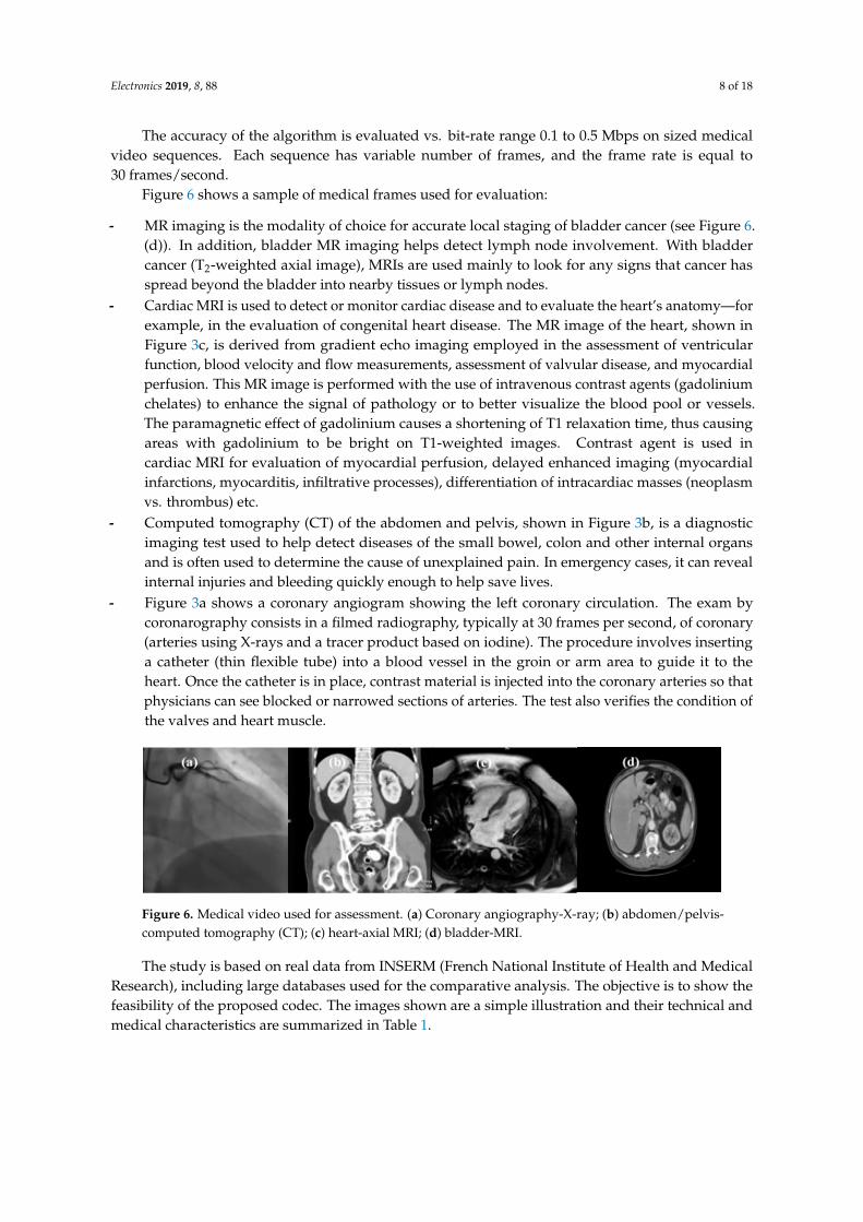
Figure 6 shows a sample of medical frames used for evaluation:
- MR imaging is the modality of choice for accurate local staging of bladder cancer (see Figure 6.(d)). In addition, bladder MR imaging helps detect lymph node involvement. With bladdercancer (T2-weighted axial image), MRIs are used mainly to look for any signs that cancer hasspread beyond the bladder into nearby tissues or lymph nodes.
- Cardiac MRI is used to detect or monitor cardiac disease and to evaluate the heart’s anatomy—forexample, in the evaluation of congenital heart disease. The MR image of the heart, shown inFigure 3c, is derived from gradient echo imaging employed in the assessment of ventricularfunction, blood velocity and flow measurements, assessment of valvular disease, and myocardialperfusion. This MR image is performed with the use of intravenous contrast agents (gadoliniumchelates) to enhance the signal of pathology or to better visualize the blood pool or vessels.The paramagnetic effect of gadolinium causes a shortening of T1 relaxation time, thus causingareas with gadolinium to be bright on T1-weighted images. Contrast agent is used incardiac MRI for evaluation of myocardial perfusion, delayed enhanced imaging (myocardialinfarctions, myocarditis, infiltrative processes), differentiation of intracardiac masses (neoplasmvs. thrombus) etc.
- Computed tomography (CT) of the abdomen and pelvis, shown in Figure 3b, is a diagnosticimaging test used to help detect diseases of the small bowel, colon and other internal organsand is often used to determine the cause of unexplained pain. In emergency cases, it can revealinternal injuries and bleeding quickly enough to help save lives.
- Figure 3a shows a coronary angiogram showing the left coronary circulation. The exam bycoronarography consists in a filmed radiography, typically at 30 frames per second, of coronary(arteries using X-rays and a tracer product based on iodine). The procedure involves insertinga catheter (thin flexible tube) into a blood vessel in the groin or arm area to guide it to theheart. Once the catheter is in place, contrast material is injected into the coronary arteries so thatphysicians can see blocked or narrowed sections of arteries. The test also verifies the condition ofthe valves and heart muscle.
Electronics 2019, 8, x FOR PEER REVIEW 8 of 18
cancer (T2-weighted axial image), MRIs are used mainly to look for any signs that cancer has spread beyond the bladder into nearby tissues or lymph nodes.
- Cardiac MRI is used to detect or monitor cardiac disease and to evaluate the heart’s anatomy—for example, in the evaluation of congenital heart disease. The MR image of the heart, shown in Figure 3c, is derived from gradient echo imaging employed in the assessment of ventricular function, blood velocity and flow measurements, assessment of valvular disease, and myocardial perfusion. This MR image is performed with the use of intravenous contrast agents (gadolinium chelates) to enhance the signal of pathology or to better visualize the blood pool or vessels. The paramagnetic effect of gadolinium causes a shortening of T1 relaxation time, thus causing areas with gadolinium to be bright on T1-weighted images. Contrast agent is used in cardiac MRI for evaluation of myocardial perfusion, delayed enhanced imaging (myocardial infarctions, myocarditis, infiltrative processes), differentiation of intracardiac masses (neoplasm vs. thrombus) etc.
- Computed tomography (CT) of the abdomen and pelvis, shown in Figure 3b, is a diagnostic imaging test used to help detect diseases of the small bowel, colon and other internal organs and is often used to determine the cause of unexplained pain. In emergency cases, it can reveal internal injuries and bleeding quickly enough to help save lives.
- Figure 3a shows a coronary angiogram showing the left coronary circulation. The exam by coronarography consists in a filmed radiography, typically at 30 frames per second, of coronary (arteries using X-rays and a tracer product based on iodine). The procedure involves inserting a catheter (thin flexible tube) into a blood vessel in the groin or arm area to guide it to the heart. Once the catheter is in place, contrast material is injected into the coronary arteries so that physicians can see blocked or narrowed sections of arteries. The test also verifies the condition of the valves and heart muscle.
Figure 6. Medical video used for assessment. (a) Coronary angiography-X-Ray; (b) abdomen /pelvis-computed tomography (CT); (c) heart-axial MRI; (d) bladder-MRI.
The study is based on real data from INSERM (French National Institute of Health and Medical Research), including large databases used for the comparative analysis. The objective is to show the feasibility of the proposed codec. The images shown are a simple illustration and their technical and medical characteristics are summarized in Table 1.
The results presented in this paper are based on a statistical study (Mean, 95% confidence interval, mean squared error/peak signal-to-noise ratio (MSE/PSNR)). Each value represents an average over a large sample of sequences (see Table 1).
Table 1. Details and characteristics of all standards tested video.
Anatomical Region/Modality Number of
Frames Number of
Frames/Second Width × Heigh Video Format
Brain-MRI (T2-weighted image acquired at 3 T) 144 30 240 × 240 AVI Bladder-MRI (T2-weighted axial image) 662 30 480 × 320 AVI
Heart-MRI (Gradient echo imaging) 87 30 340 × 336 AVI Abdomen/pelvis-CT 295 30 340 × 352 AVI
Coronary angiogram-X-Ray (+a tracer product based on iodine) 594 30 360 × 360 AVI
Figure 6. Medical video used for assessment. (a) Coronary angiography-X-ray; (b) abdomen/pelvis-computed tomography (CT); (c) heart-axial MRI; (d) bladder-MRI.
The study is based on real data from INSERM (French National Institute of Health and MedicalResearch), including large databases used for the comparative analysis. The objective is to show thefeasibility of the proposed codec. The images shown are a simple illustration and their technical andmedical characteristics are summarized in Table 1.

Electronics 2019, 8, 88 9 of 18
Table 1. Details and characteristics of all standards tested video.
Anatomical Region/Modality Number ofFrames
Number ofFrames/Second
Width × HeighVideo Format
Brain-MRI (T2-weighted image acquired at 3 T) 144 30 240 × 240 AVIBladder-MRI (T2-weighted axial image) 662 30 480 × 320 AVI
Heart-MRI (Gradient echo imaging) 87 30 340 × 336 AVIAbdomen/pelvis-CT 295 30 340 × 352 AVI
Coronary angiogram-X-ray (+a tracer productbased on iodine) 594 30 360 × 360 AVI
The results presented in this paper are based on a statistical study (Mean, 95% confidence interval,mean squared error/peak signal-to-noise ratio (MSE/PSNR)). Each value represents an average over alarge sample of sequences (see Table 1).
The perceived quality of recovered frames has been measured. Moreover, a comparison betweenBandelet-SPIHT versus wavelet transform using SPIHT encoder, MPEG-4, and H.26x is carried.
To evaluate the quality of the compressed image, subjective and objective quality measures areused. But subjective quality measures based upon group of observers are too time consuming [28–31].So, objective quality measures such as MSE, PSNR etc. are preferred.
4.1. Objective Measurement of Video Quality
For the analysis of decoded video, we can distinguish data metrics, which measure the fidelity ofthe signal without considering its content, and picture metrics, which treat the video data as the visualinformation that it contains. For compressed video delivery over packet networks, there are also packet-or bitstream-based metrics, which look at the packet header information and the encoded bitstreamdirectly without fully decoding the video. Furthermore, metrics can be classified into full-reference,no-reference and reduced-reference metrics based on the amount of reference information they require.
4.1.1. Data Metrics
The image and video processing community has long been using MSE and PSNR as fidelitymetrics (mathematically, PSNR is just a logarithmic representation of MSE). There are a number ofreasons for the popularity of these two metrics. The formulas for computing them are as simple tounderstand and implement as they are easy and fast to compute. Minimizing MSE is also very wellunderstood from a mathematical point of view. Over the years, video researchers have developed afamiliarity with PSNR that allows them to interpret the values immediately. There is probably no othermetric as widely recognized as PSNR, which is also due to the lack of alternative standards.
Despite its popularity, PSNR only has an approximate relationship with the video qualityperceived by human observers, simply because it is based on a byte-by-byte comparison of thedata without considering what they actually represent. PSNR is completely ignorant to things as basicas pixels and their spatial relationship, or things as complex as the interpretation of images and imagedifferences by the human visual system.
PSNR is the ratio between the maximum possible power of a signal and the power of noise. PSNRis usually expressed in terms of the logarithmic decibel
PSNR = 10 log10
((2n − 1)
MSE
)(2)
where
• (2n − 1) is the dynamic of the signal. In the standard case, (2n − 1) = 255 is maximum possibleamplitude for an 8-bit image.

Electronics 2019, 8, 88 10 of 18
• MSE represents the mean square error between two frames, namely the original frame f (i, j) andthe recovered frame fr(i, j) of size M× N and is given by:
MSE =1
MN
M
∑i=1
N
∑j=1
( f (i, j)− fr(i, j))2 (3)
MSE can be identified as the power of noise.
The PSNR is an easy, fast and very popular quality measurement metric, widely used to comparethe quality of video encoding and decoding. Although a high PSNR generally means a good qualityreconstruction, this is not always the case. Indeed, PSNR requires original image for comparison, butthis may not be available in every case, also PSNR does not correlate well with subjective video qualitymeasures, so is not very suitable for perceived visual quality.
4.1.2. Picture Metrics
As an alternative to data metrics described above, better visual quality measures have beendesigned taking into account the effects of distortions on perceived quality.
An engineering approach consists primarily on the extraction and analysis of certain featuresor artifacts in the video. These can be either structural image elements such as contours, or specificdistortions that are introduced by a particular video processing step, compression technology ortransmission link, such as block artifacts. This does not necessarily mean that such metrics disregardhuman vision, as they often consider psychophysical effects as well, but image content and distortionanalysis rather than fundamental vision modeling is the conceptual basis for their design.
1. Image Quality Assessment using Structural Similarity (SSIM) index
Wang et al.’s structural similarity (SSIM) index [32] computes the mean, variance and covarianceof small patches inside a frame and combines the measurements into a distortion map.
Two image signals x and y are aligned with each other (e.g., spatial patches extracted from eachimage). If we consider one of the signals to have perfect quality, then the similarity measure can serveas a quantitative measurement of the quality of the second signal.
SSIM index introduces three key features: luminance l, contrast c and structure s. This metrics isdefined in (4):
SSIM( f , fr) = l( f , fr)× c( f , fr)× s( f , fr) (4)
- The luminance comparison l(x, y) is defined as a function of the mean intensities Mx and My ofsignals x et y:
l(x, y) =2Mx My + C1
M2x + M2
y + C1(5)
where
Mx =1N
N
∑i=1
xi and My =1N
N
∑i=1
yi
and the constant C1 is included to avoid instability when M2x + M2
y is close to zero (similarconsiderations for the presence of C2 and C3).
- The contrast comparison c(x, y) is function of standard deviations σx and σy, and takes thefollowing form:
c(x, y) =2σxσy + C2
σ2x + σ2
y + C2(6)
where the standard deviation of x is

Electronics 2019, 8, 88 11 of 18
σx =
(1
N − 1
N
∑i=1
(x2i − (Mx)
2)
)1/2
- A simple and effective measure to quantify the structural similarity s(x, y) is the estimation of thecorrelation coefficient σxy between x and y. The structure comparison s(x, y) is defined as follows:
s(x, y) =σxy + C3
σxσy + C3(7)
where the covariance of x and y is
σxy =1
N − 1
N
∑i=1
xiyi −Mx My
Specifically, it is possible to choose Ci = K2i D2, i = 1, and Ki is a constant, such as Ki 1 and
D is the dynamic range of the pixel values (D = 255 corresponds to a grey-scale digital image whenthe number of bits/pixel is 8). For C3 = C2
2 , the explicit expression of the structural similarity (SSIM)index is:
SSIM(x, y) =
(2Mx My + C1
)(2σxy + C2
)(M2
x + M2y + C1
)(σ2
x + σ2y + C2
) (8)
SSIM is symmetrical and less than or equal to one (it is equal to one if and only if f = fr, i.e., ifx = y in expression (8)).
Generally, over the whole video coding, a mean value of SSIM is required as mean SSIM (MSSIM):
MSSIM( f , fr) =1L
L
∑i=1
SSIM( fi, fri) (9)
where fi and fri are the contents of frames (original and recovered respectively) at the ith local window(or sub-image), and L is the total of local windows number in frame.
The MSSIM values exhibit greater consistency with the visual quality.
2. Image Quality Assessment using Video Fidelity (VIF) index
Sheikh and Bovik [33] proposed a new paradigm for video quality assessment: visual informationfidelity (VIF). This criterion quantifies the Shannon information that is shared between the originaland recovered images relative to the contained information in the original image itself. It uses naturalscene statistics modelling in conjunction with an image-degradation model and a human visual system(HVS) model.
Visual information fidelity uses the Gaussian scale mixture model in the wavelet domain.To obtain VIF one performs a scale-space-orientation wavelet decomposition using the steerablepyramid and models each sub-band in the source as C = SU, where S is a random field of scalars andU is a Gaussian vector.
The distortion model is GC + n where G is a scalar gain field and n is an additive Gaussian noise.VIF then assumes that the distorted and source images pass through the human visual system
and the HVS uncertainty is modelled as visual noise N.The model is then:
Reference signal E = C + N (10)
Test signal F = D + N (11)

Electronics 2019, 8, 88 12 of 18
where E and F denote the visual signal at the output of the HVS model from the reference and the testvideos respectively (see Figure 7), from which the brain extracts cognitive information.Electronics 2019, 8, x FOR PEER REVIEW 12 of 18
Figure 7. Diagram of the visual information fidelity (VIF) metric.
VIF measure takes values between 0 and 1, where 1 means perfect quality. Thus the visual information fidelity (VIF) measure is given by: VIF = ∑ 𝐼 𝐶 ; 𝐹 /𝑠∑ 𝐼(𝐶 ; 𝐸 /𝑠 )
(12)
where 𝐼(𝑋; 𝑌 𝑧⁄ ) is the conditional mutual information between 𝑋 and 𝑌 given 𝑧, C denotes the random field from a channel in the original image, 𝑠 is a realization of 𝑆 for a particular image and the index j runs through all the sub bands in the decomposed image.
4.2. Subjective Quality Assessment
The reference for multimedia quality are subjective experiments, which represent the most accurate method for obtaining quality ratings. In subjective experiments, a number of “subjects”, clinicians and PhD students in our study case, (typically 15–30) are asked to watch a set of medical video and rate their quality. The average rating over all viewers for a given database is also known as the mean opinion score (MOS) [28]. Since each individual has different interests and expectations for video, the subjectivity and variability of the viewer ratings cannot be completely eliminated.
Subjective experiments are invaluable tools for assessing multimedia quality. Their main shortcoming is the requirement for a large number of viewers, which limits the amount of video material that can be rated in a reasonable amount of time; they are neither intended nor practical for 24/7 in-service monitoring applications. Nonetheless, subjective experiments remain the benchmark for any objective quality metric.
4.3. Choice of Optimal Wavelet Filters
In wavelet-based image coding, a variety of orthogonal and biorthogonal filters have been developed for compression. The selection of wavelet filters plays a crucial part in achieving an effective coding performance, because there is no filter that performs the best for all images.
Our aim here is to suggest the most suitable wavelet filter for different test images based upon the quality measures introduced above.
To achieve a high compression rate, it is often necessary to choose the best wavelet filter bank (see Mallat algorithm [3,4]) and decomposition level, which will play a crucial role in compressing the images. The choice of optimal wavelets has several criteria. The main criteria are:
• Compact support size. • Regularity and degree of smoothness. • Symmetry. • Orthogonality and biorthogonality of the resulting analysis.
Compact support size lead to efficient implementation, regularity, and degree of smoothness (related to filter order or can filter length), symmetry is useful in avoiding dephasing in image processing, and orthogonality allows fast algorithm [3].
Figure 7. Diagram of the visual information fidelity (VIF) metric.
VIF measure takes values between 0 and 1, where 1 means perfect quality.Thus the visual information fidelity (VIF) measure is given by:
VIF =∑j I
(Cj; Fj/sj)
∑j I(Cj; Ej/sj
) (12)
where I(X; Y/z) is the conditional mutual information between X and Y given z, C denotes the randomfield from a channel in the original image, sj is a realization of Sj for a particular image and the index jruns through all the sub bands in the decomposed image.
4.2. Subjective Quality Assessment
The reference for multimedia quality are subjective experiments, which represent the mostaccurate method for obtaining quality ratings. In subjective experiments, a number of “subjects”,clinicians and PhD students in our study case, (typically 15–30) are asked to watch a set of medicalvideo and rate their quality. The average rating over all viewers for a given database is also known asthe mean opinion score (MOS) [28]. Since each individual has different interests and expectations forvideo, the subjectivity and variability of the viewer ratings cannot be completely eliminated.
Subjective experiments are invaluable tools for assessing multimedia quality. Their mainshortcoming is the requirement for a large number of viewers, which limits the amount of videomaterial that can be rated in a reasonable amount of time; they are neither intended nor practical for24/7 in-service monitoring applications. Nonetheless, subjective experiments remain the benchmarkfor any objective quality metric.
4.3. Choice of Optimal Wavelet Filters
In wavelet-based image coding, a variety of orthogonal and biorthogonal filters have beendeveloped for compression. The selection of wavelet filters plays a crucial part in achieving an effectivecoding performance, because there is no filter that performs the best for all images.
Our aim here is to suggest the most suitable wavelet filter for different test images based uponthe quality measures introduced above.
To achieve a high compression rate, it is often necessary to choose the best wavelet filter bank(see Mallat algorithm [3,4]) and decomposition level, which will play a crucial role in compressing theimages. The choice of optimal wavelets has several criteria. The main criteria are:
• Compact support size.• Regularity and degree of smoothness.• Symmetry.• Orthogonality and biorthogonality of the resulting analysis.

Electronics 2019, 8, 88 13 of 18
Compact support size lead to efficient implementation, regularity, and degree of smoothness(related to filter order or can filter length), symmetry is useful in avoiding dephasing in imageprocessing, and orthogonality allows fast algorithm [3].
In this experiment, MRI video is encoded using the Bandelet-SPIHT algorithm for various bitrates. In order to find the most suitable wavelet filter for different test images based upon objectivequality measures for video compression, biorthogonal family was considered. Thus, biorthogonalwavelets CDF (Cohen–Daubechies–Feauveau) 9/7 (nine coefficients in decomposition low-pass andseven in decomposition highpass filters) and Le Gall 5/3 (five coefficients in decomposition low-passand three in decomposition high-pass filters) are selected.
The choice of these filters is justified by their simplicity, symmetry and their compact support(localization in space).
By a subjective quality assessment of images shown in Figure 8, we opt for CDF 9/7, whichreduces the level of artifacts. Indeed, the obtained results show that the recovered frame using thebandelet algorithm + SPIHT is close to the original frame.
Electronics 2019, 8, x FOR PEER REVIEW 13 of 18
In this experiment, MRI video is encoded using the Bandelet-SPIHT algorithm for various bit rates. In order to find the most suitable wavelet filter for different test images based upon objective quality measures for video compression, biorthogonal family was considered. Thus, biorthogonal wavelets CDF (Cohen–Daubechies–Feauveau) 9/7 (nine coefficients in decomposition low-pass and seven in decomposition highpass filters) and Le Gall 5/3 (five coefficients in decomposition low-pass and three in decomposition high-pass filters) are selected.
The choice of these filters is justified by their simplicity, symmetry and their compact support (localization in space).
By a subjective quality assessment of images shown in Figure 8, we opt for CDF 9/7, which reduces the level of artifacts. Indeed, the obtained results show that the recovered frame using the bandelet algorithm + SPIHT is close to the original frame.
It is worth noting the presence of blurred areas in the image when Le Gall 5/3 filters are used. Objective measurement of video quality (PSNR, SSIM and VIF) between (bandelet + SPIHT)
algorithm and (wavelet + SPIHT) applied to coronary angiography test frame at various bit rates are illustrated in Figure 9.
(a) Original (b) Le Gall 5/3 filter (c) CDF9/7 filter
Figure 8. Recovered frames using: (b) Bandelet (Le Gall 5/3)-SPIHT and (c) Bandelet (CDF9/7)-SPIHT at 0.2 Mbps.
Figure 9. Performance evaluation of bandelet-SPIHT versus (wavelet) SPIHT in terms of objective metrics (peak signal-to-noise ratio (PSNR), mean structural similarity (MSSIM) and VIF).
Figure 10 is an illustration of a sample of medical images from our large databases used for benchmarking (subjective quality assessment by visual inspection).
The images shown in Figure 10 are a simple illustration and their technical and medical characteristics are summarized in Table 1 (see also Figure 6). They represent: (a) Coronary angiography-X-Ray; (b) abdomen /pelvis-computed tomography (CT); (c) heart-axial MRI; (d) bladder-MRI.
0.1 0.15 0.2 0.25 0.3 0.35 0.4 0.45 0.510
15
20
25
30
35
40
BITRATE(Mbps)
PS
NR
(dB
)
Wavelet-SPIHTBandelet-SPIHT
0.1 0.15 0.2 0.25 0.3 0.35 0.4 0.45 0.50.4
0.5
0.6
0.7
0.8
0.9
1
BITRATE(Mbps)
MS
SIM
Wavelet-SPIHTBandelet-SPIHT
0.1 0.15 0.2 0.25 0.3 0.35 0.4 0.45 0.50
0.1
0.2
0.3
0.4
0.5
0.6
0.7
0.8
BITRATE(Mbps)
VIF
Wavelet-SPIHTBandelet-SPIHT
Figure 8. Recovered frames using: (b) Bandelet (Le Gall 5/3)-SPIHT and (c) Bandelet (CDF9/7)-SPIHTat 0.2 Mbps.
It is worth noting the presence of blurred areas in the image when Le Gall 5/3 filters are used.Objective measurement of video quality (PSNR, SSIM and VIF) between (bandelet + SPIHT)
algorithm and (wavelet + SPIHT) applied to coronary angiography test frame at various bit rates areillustrated in Figure 9.
Electronics 2019, 8, x FOR PEER REVIEW 13 of 18
In this experiment, MRI video is encoded using the Bandelet-SPIHT algorithm for various bit rates. In order to find the most suitable wavelet filter for different test images based upon objective quality measures for video compression, biorthogonal family was considered. Thus, biorthogonal wavelets CDF (Cohen–Daubechies–Feauveau) 9/7 (nine coefficients in decomposition low-pass and seven in decomposition highpass filters) and Le Gall 5/3 (five coefficients in decomposition low-pass and three in decomposition high-pass filters) are selected.
The choice of these filters is justified by their simplicity, symmetry and their compact support (localization in space).
By a subjective quality assessment of images shown in Figure 8, we opt for CDF 9/7, which reduces the level of artifacts. Indeed, the obtained results show that the recovered frame using the bandelet algorithm + SPIHT is close to the original frame.
It is worth noting the presence of blurred areas in the image when Le Gall 5/3 filters are used. Objective measurement of video quality (PSNR, SSIM and VIF) between (bandelet + SPIHT)
algorithm and (wavelet + SPIHT) applied to coronary angiography test frame at various bit rates are illustrated in Figure 9.
(a) Original (b) Le Gall 5/3 filter (c) CDF9/7 filter
Figure 8. Recovered frames using: (b) Bandelet (Le Gall 5/3)-SPIHT and (c) Bandelet (CDF9/7)-SPIHT at 0.2 Mbps.
Figure 9. Performance evaluation of bandelet-SPIHT versus (wavelet) SPIHT in terms of objective metrics (peak signal-to-noise ratio (PSNR), mean structural similarity (MSSIM) and VIF).
Figure 10 is an illustration of a sample of medical images from our large databases used for benchmarking (subjective quality assessment by visual inspection).
The images shown in Figure 10 are a simple illustration and their technical and medical characteristics are summarized in Table 1 (see also Figure 6). They represent: (a) Coronary angiography-X-Ray; (b) abdomen /pelvis-computed tomography (CT); (c) heart-axial MRI; (d) bladder-MRI.
0.1 0.15 0.2 0.25 0.3 0.35 0.4 0.45 0.510
15
20
25
30
35
40
BITRATE(Mbps)
PS
NR
(dB
)
Wavelet-SPIHTBandelet-SPIHT
0.1 0.15 0.2 0.25 0.3 0.35 0.4 0.45 0.50.4
0.5
0.6
0.7
0.8
0.9
1
BITRATE(Mbps)
MS
SIM
Wavelet-SPIHTBandelet-SPIHT
0.1 0.15 0.2 0.25 0.3 0.35 0.4 0.45 0.50
0.1
0.2
0.3
0.4
0.5
0.6
0.7
0.8
BITRATE(Mbps)
VIF
Wavelet-SPIHTBandelet-SPIHT
Figure 9. Performance evaluation of bandelet-SPIHT versus (wavelet) SPIHT in terms of objectivemetrics (peak signal-to-noise ratio (PSNR), mean structural similarity (MSSIM) and VIF).
Figure 10 is an illustration of a sample of medical images from our large databases used forbenchmarking (subjective quality assessment by visual inspection).
The images shown in Figure 10 are a simple illustration and their technical and medicalcharacteristics are summarized in Table 1 (see also Figure 6). They represent: (a) Coronary angiography-X-ray; (b) abdomen/pelvis-computed tomography (CT); (c) heart-axial MRI; (d) bladder-MRI.

Electronics 2019, 8, 88 14 of 18
Electronics 2019, 8, x FOR PEER REVIEW 14 of 18
(a) (b) (c) (d)
Figure 10. Comparative subjective quality assessments medical video using bandelet (CDF9/7)-SPIHT (top row), and wavelet (CDF9/7)-SPIHT (Bottom row) at 0.5 Mbps. (a) Coronary angiography-X-Ray; (b) abdomen /pelvis-computed tomography (CT); (c) heart-axial MRI; (d) bladder-MRI.
From these results, illustrated by some examples in Figures 8–10, we can draw three conclusions:
1 The performance of bandelet-SPIHT algorithm is superior to that of SPIHT (wavelet-based). 2 Bandelet-SPIHT is able to capture complex geometric contents of images and surfaces and
reduce drastically existing redundancy in video while classical SPIHT (based on discrete wavelet transform) is subject to artifacts.
3 The bandelet-SPIHT algorithm gives better results in the case of CDF 9/7 wavelet filters than in the case of Le Gall 5/3.
4.4. Bandelet-SPIHT Versus Standard Encoders Comparison
Advanced video coding (AVC), also known as H.264/MPEG-4, and its successor high-efficiency video coding (HEVC), also known as H.265 and MPEG-H Part 2, are compared to the proposed coder bandelet-SPIHT using data metrics, namely PSNR (dB).
Figure 11 shows the performance, in terms of PSNR vs bitrate, of three compression techniques H264/AVC, H265/HEVC and bandelet-SPIHT. Each value represents an average within its confidence interval. For example, for 270 kbps, the PSNR obtained by bandelet-SPIHT is higher than that produced by the other methods and its confidence interval is tightened around the mean value. On the other hand, for 2260 kbps, the PSNR obtained by bandelet-SPIHT is lower than that produced by HEVC. In addition, its confidence interval is asymmetric with a greater tendency towards lower values. Consequently, we will have little confidence in this average value obtained by the algorithm proposed for high data rates.
As illustrated in Figure 11, the proposed method demonstrates a relatively better performance compared to the standard video coding AVC and HEVC in terms of PSNR. For example, for a bit rate greater than 1.3 Mbps, it is clear that in terms of PSNR, the performance of the proposed algorithm (bandelet-SPIHT) is lower than that of HEVC but almost always higher than that of AVC. And for low bit rates, our encoder outperforms video coding standards. For example, for 0.6 Mbps, our method exceeds AVC and HEVC by 3 dB and 0.5 dB respectively.
And for low bit rates, our encoder outperforms video coding standards. For example, for 0.6 Mbps, our method exceeds AVC and HEVC by 3 dB and 0.5 dB respectively.
Figure 10. Comparative subjective quality assessments medical video using bandelet (CDF9/7)-SPIHT(top row), and wavelet (CDF9/7)-SPIHT (Bottom row) at 0.5 Mbps. (a) Coronary angiography-X-ray;(b) abdomen/pelvis-computed tomography (CT); (c) heart-axial MRI; (d) bladder-MRI.
From these results, illustrated by some examples in Figures 8–10, we can draw three conclusions:
1 The performance of bandelet-SPIHT algorithm is superior to that of SPIHT (wavelet-based).2 Bandelet-SPIHT is able to capture complex geometric contents of images and surfaces and
reduce drastically existing redundancy in video while classical SPIHT (based on discrete wavelettransform) is subject to artifacts.
3 The bandelet-SPIHT algorithm gives better results in the case of CDF 9/7 wavelet filters than inthe case of Le Gall 5/3.
4.4. Bandelet-SPIHT Versus Standard Encoders Comparison
Advanced video coding (AVC), also known as H.264/MPEG-4, and its successor high-efficiencyvideo coding (HEVC), also known as H.265 and MPEG-H Part 2, are compared to the proposed coderbandelet-SPIHT using data metrics, namely PSNR (dB).
Figure 11 shows the performance, in terms of PSNR vs bitrate, of three compression techniquesH264/AVC, H265/HEVC and bandelet-SPIHT. Each value represents an average within its confidenceinterval. For example, for 270 kbps, the PSNR obtained by bandelet-SPIHT is higher than that producedby the other methods and its confidence interval is tightened around the mean value. On the otherhand, for 2260 kbps, the PSNR obtained by bandelet-SPIHT is lower than that produced by HEVC.In addition, its confidence interval is asymmetric with a greater tendency towards lower values.Consequently, we will have little confidence in this average value obtained by the algorithm proposedfor high data rates.
As illustrated in Figure 11, the proposed method demonstrates a relatively better performancecompared to the standard video coding AVC and HEVC in terms of PSNR. For example, for a bit rategreater than 1.3 Mbps, it is clear that in terms of PSNR, the performance of the proposed algorithm(bandelet-SPIHT) is lower than that of HEVC but almost always higher than that of AVC. And for lowbit rates, our encoder outperforms video coding standards. For example, for 0.6 Mbps, our methodexceeds AVC and HEVC by 3 dB and 0.5 dB respectively.
And for low bit rates, our encoder outperforms video coding standards. For example, for 0.6 Mbps,our method exceeds AVC and HEVC by 3 dB and 0.5 dB respectively.

Electronics 2019, 8, 88 15 of 18
It is well-known that complex images, fast camera movements and action scenes require highbitrate. In this context, HEVC is the most efficient technology to date.
Electronics 2019, 8, x FOR PEER REVIEW 15 of 18
It is well-known that complex images, fast camera movements and action scenes require high bitrate. In this context, HEVC is the most efficient technology to date.
Figure 11. Performance analysis in terms of PSNR (dB) between standard coding methods and the proposed method.
Those with fixed scenes, which are easier to encode, require a slower rate, as is the case in medical imaging. In this context, bandelet-SPIHT is superior at low bitrates due to its ability to capture the geometric complexity of the image structure and its multi-resolution analysis.
For the tests, we used an improved version of HEVC sometimes called HEVC screen content coding extension. This standardization effort was developed to leverage the unique characteristics of computer-generated and digitally-captured videos. The intra block copy mode takes advantage of the presence of exact copies of blocks between different pictures in a video sequence.
The test conditions include video sequences comprising a variety of resolutions and content types (text and graphics with motion, camera-captured content, mixed content and animation). For each sequence, two color formats are tested. One is in RGB and the other is in Y CB CR (Y is the luma component and CB and CR are the blue-difference and red-difference chroma components) and several of the 4:2:0 sequences are generated from their 4:4:4 correspondences.
Three test configurations, i.e., all intra (AI), random access (RA) and low-delay B (LB) were used. For lossy coding, four QPs (quantization parameters), 22, 27, 32, 37, were applied.
The statistical study we have carried out is in line with the recommendations of ITU—Telecommunications Standardization Sector, and more specifically the Video Coding Experts Group.
Indeed, the benchmarking used to measure performance of HEVC and the proposed codec was made partly by experts in video via quality criteria adapted to the human visual system such as SSIM and VIF (objective quality metrics) and partly by clinicians or PhD students (subjective quality assessment) from our medical research institute (INSERM). However, the subjective improvement measured somewhat exceeds the improvement measured by the PSNR metric.
4.5. Computational Complexity
We cannot directly compare the temporal performance of the proposed algorithm with that of H264/AVC and H265/HEVC, due to their structural difference and their compression concept based on totally different philosophies. However, we will develop and clarify this issue, which is crucial to understanding the purpose of our work.
0 500 1000 1500 2000 2500 29
30 31 32 33 34
35 36 37 38 39
BITRATE (kbps)
PSN
R
(dB)
H.264 MPEG4/AVC
H.265 HEVC CC Bandelet-SPIHT
Figure 11. Performance analysis in terms of PSNR (dB) between standard coding methods and theproposed method.
Those with fixed scenes, which are easier to encode, require a slower rate, as is the case in medicalimaging. In this context, bandelet-SPIHT is superior at low bitrates due to its ability to capture thegeometric complexity of the image structure and its multi-resolution analysis.
For the tests, we used an improved version of HEVC sometimes called HEVC screen contentcoding extension. This standardization effort was developed to leverage the unique characteristics ofcomputer-generated and digitally-captured videos. The intra block copy mode takes advantage of thepresence of exact copies of blocks between different pictures in a video sequence.
The test conditions include video sequences comprising a variety of resolutions and content types(text and graphics with motion, camera-captured content, mixed content and animation). For eachsequence, two color formats are tested. One is in RGB and the other is in Y CB CR (Y is the lumacomponent and CB and CR are the blue-difference and red-difference chroma components) and severalof the 4:2:0 sequences are generated from their 4:4:4 correspondences.
Three test configurations, i.e., all intra (AI), random access (RA) and low-delay B (LB) were used.For lossy coding, four QPs (quantization parameters), 22, 27, 32, 37, were applied.
The statistical study we have carried out is in line with the recommendations of ITU—Telecommunications Standardization Sector, and more specifically the Video Coding Experts Group.
Indeed, the benchmarking used to measure performance of HEVC and the proposed codec wasmade partly by experts in video via quality criteria adapted to the human visual system such asSSIM and VIF (objective quality metrics) and partly by clinicians or PhD students (subjective qualityassessment) from our medical research institute (INSERM). However, the subjective improvementmeasured somewhat exceeds the improvement measured by the PSNR metric.
4.5. Computational Complexity
We cannot directly compare the temporal performance of the proposed algorithm with that ofH264/AVC and H265/HEVC, due to their structural difference and their compression concept basedon totally different philosophies. However, we will develop and clarify this issue, which is crucial tounderstanding the purpose of our work.

Electronics 2019, 8, 88 16 of 18
We will focus on two fundamental differences between the MPEG4 family (AVC and HEVC)and bandelet-SPIHT:
Unlike MPEG4’s (H264/AVC and H265/HEVC) use of both intra- and inter-frame encoding,bandelet-SPIHT employs only intra-frame encoding. This means that each frame is compressedindividually, and no attention is paid by the encoder to either previous or following frames, and so itis not predictive in any way.
Consequently, for bandelet-SPIHT the (time) latency to compress a frame is shorter (as the codecdoes not have to rely on generating forward and reverse differences between frames).
The type of transform used by AVC and HEVC is DCT while our compression algorithm uses2nd-generation wavelets (bandelet transform).
For an image of pixels, the computational complexity of the best bandelet basis algorithmis O
(N3/2
)whereas for the DCT the computational complexity can be approximated by
O(
N2 ((log2 N)− 1)
). This shows that the calculation of bandelet transform is more complex than that
of the DCTFrom these two considerations, we can conclude that the computation time required
for H264/AVC compression is comparable to that of bandelet-SPIHT, which has beenconfirmed experimentally.
For high spatial resolution videos, the increase of computational complexity for HEVC is about25% on the average compared to AVC (and thus for bandelet-SPIHT), which seems quite reasonablewith considerations of significant coding efficiency improvements.
Therefore, we can conclude that the computational complexity between bandelet-SPIHT andH264/AVC is of the same order, whereas that of HEVC is significantly higher. However, H.265/HEVCtechnology has the capability of doubling the compression efficiency of H.264/AVC. What this means isthat H.265 uses only half the bitrate otherwise used by H.264/AVC when transmitting images [9,10]. So,H.265/HEVC significantly reduces the storage and bandwidth requirements during video encoding,which is highly beneficial for both software and hardware usage.
5. Conclusions
The objective motivating our study was to propose a coding method with high performancesin terms of visual quality and PSNR at low bit rates. The bandelets using a SPIHT encoder is aneffective condidate meeting the specific requirements of our application in the medical field andparticulary in medical imaging where the quality of the image at low bit rates is a major requirementfor the practitioner.
In order to show the efficiency of bandelet-SPIHT algorithm, a set of medical sequences as testexamples is considered. At low bit rates, the bandelet-SPIHT algorithm gives significantly better results(PSNR metric) comparing to some cutting-edge coding techniques such as H.26x family (namely H.264and H.265). In addition, the computational complexity of the proposed algorithm is of the same orderof magnitude as that of H264/AVC but significantly lower than that of H265/HEVC.
From this point of view, the expected goal is achieved and the prospects for application in medicalimaging are promising.
Geometric image compression methods are a very dynamic search direction. One could mentionthe construction of transformations that adapt automatically to the geometry without the need tospecify it. A consensus is growing in the scientific community that geometry is the key to significantlyimprove current compression methods. However, HEVC compressed videos may incur severe qualitydegradation, particularly at low bit-rates. Thus, it is necessary to enhance the visual quality of HEVCvideos at the decoder side.
It is in this area that improvements are expected and research is ongoing [34]. Another useful wayis to improve objective metrics [35] to evaluate the quality of videos automatically.

Electronics 2019, 8, 88 17 of 18
Author Contributions: Methodology, validation, writing—review and editing, A.O.; Project administration,A.T.-A.; Software, M.F. and Y.H.; Supervision, M.A.
Funding: This research received no external funding.
Acknowledgments: We thank BELADGHEM for the advice provided to HABCHI during his PhD thesis inimage compression.
Conflicts of Interest: The authors declare no conflict of interest.
References
1. Djeddi, M.; Ouahabi, A.; Batatia, H.; Basarab, A.; Kouamé, D. Discrete wavelet transform for multifractaltexture classification: Application to ultrasound imaging. In Proceedings of the IEEE InternationalConference on Image Processing (IEEE ICIP2010), Hong Kong, China, 26–29 September 2010; pp. 637–640.
2. Sayood, K. Introduction to Data Compression, 5th ed.; The Morgan Kaufmann Series in Multimedia Informationand Systems; Elsevier: Amsterdam, The Netherlands, 2017; ISBN 9780128094747.
3. Ouahabi, A. Signal and Image Multiresolution Analysis; Wiley-ISTE: Hoboken, NJ, USA, 2012;ISBN 978-1-848-21257-2.
4. Mallat, S. A Wavelet Tour of Signal Processing: A Sparse Way, 3rd ed.; Academic Press: Cambridge, MA, USA,2009; ISBN 9780123743701.
5. Shapiro, J.M. Embedded image coding using zerotrees of wavelet coefficients. IEEE Trans. Signal Process.1993, 41, 3445–3462. [CrossRef]
6. Said, A.; Pearlman, W. A new fast and efficient image codec based on set partitioning in hierarchical trees.IEEE Trans. Circuits Syst. Video Technol. 1996, 6, 243–250. [CrossRef]
7. Cermak, G.W.; Wolf, S.; Tweedy, E.P.; Pinson, M.H.; Webster, A.A. Validating objective measures of MPEGvideo quality. SMPTE J. 2015, 107, 226–235. [CrossRef]
8. Shi, Y.Q.; Huifang, S. Image and Video Compression for Multimedia Engineering: Fundamentals, Algorithms, andStandards, 2nd ed.; CRC Press: Boca Raton, FL, USA, 2000; ISBN 9780849373640.
9. Sullivan, G.J.; Ohm, J.R.; Han, W.; Wiegand, T. Overview of the high efficiency video coding (HEVC) standard.IEEE Trans. Circuits Syst. Video Technol. 2012, 22, 1649–1668. [CrossRef]
10. Ohm, J.R.; Sullivan, G.J.; Schwarz, H.; Tan, T.K.; Wiegand, T. Comparison of the coding efficiency of videocoding standards-including high efficiency video coding (HEVC). IEEE Trans. Circuits Syst. Video Technol.2012, 22, 1669–1684. [CrossRef]
11. International Telecommunication Union. ITU-T Recommendation H.265, High Efficiency Video Coding;International Telecommunication Union: Geneva, Switzerland, 2013.
12. Ouahabi, A. Wavelet Denoising: Application in Medical Imaging; Wiley-ISTE: Hoboken, NJ, USA, 2019.13. Zehani, S.; Ouahabi, A.; Oussalah, M.; Mimi, M.; Taleb-Ahmed, A. New and robust method for trabecular
bone texture based on fractal dimension. In Proceedings of the 42nd Annual Conference of the IEEEIndustrial Electronics Society (IECON 2016), Firenze, Italy, 23–26 October 2016; pp. 992–997.
14. Ouahabi, A. Image Denoising using Wavelets: Application in Medical Imaging. In Advances in HeuristicSignal Processing and Applications; Chatterjee, A., Nobahari, H., Siarry, P., Eds.; Springer: Basel, Switzerland,2013; pp. 287–313.
15. Ouahabi, A. A review of wavelet denoising in medical imaging. In Proceedings of the International Workshopon Systems, Signal Processing and Their Applications (IEEE/WOSSPA’13), Algiers, Algeria, 12–15 May 2013;pp. 19–26.
16. Sidahmed, S.; Messali, Z.; Ouahabi, A.; Trépout, S.; Messaoudi, C.; Marco, S. Nonparametric denoisingmethods based on contourlet transform with sharp frequency localization: Application to electronmicroscopy images with low exposure time. Entropy 2015, 17, 2781–2799.
17. Katsigiannis, S.; Papaioannou, G.; Maroulis, D. A contourlet transform based algorithm for real-time videoencoding. In Proceedings of the SPIE, Real-Time Image and Video processing Conference, Brussels, Belgium,19 April 2012; Volume 8437.
18. Shu, Z.; Luo, Y.; Liu, G.; Xie, Z. Arbitrarily shape object-based video coding technology by wavelet-basedcontourlet transform. In Proceedings of the IEEE International Conference on Information and Automation,Luoyang, China, 8–10 August 2015.

Electronics 2019, 8, 88 18 of 18
19. Starck, J.L.; Murtagh, F.; Candès, E.J.; Donoho, D.L. Gray and color image contrast enhancement by thecurvelet transform. IEEE Trans. Image Process. 2003, 12, 706–717. [CrossRef] [PubMed]
20. Le Pennec, E.; Mallat, S. Sparse geometric image representations with bandelets. IEEE Trans. Image Process.2005, 14, 423–438. [CrossRef] [PubMed]
21. Yang, H.Y.; Wang, X.Y.; Niu, P.P.; Liu, Y.C. Image denoising using nonsubsampled shearlet transform andtwin support vector machines. Neural Netw. 2014, 57, 152–165. [CrossRef] [PubMed]
22. Habchi, Y.; Ouahabi, A.; Beladgham, M.; Taleb-Ahmed, A. Towards a new standard in medical videocompression. In Proceedings of the 42nd Annual Conference of the IEEE Industrial Electronics Society(IECON2016), Florence, Italy, 23–26 October 2016; pp. 1061–1066.
23. Peyre, G.; Mallat, S. Surface compression with geometric bandelets. ACM Trans. Graphics 2005, 24, 601–608.[CrossRef]
24. Peyre, G.; Mallat, S. Discrete bandelets with geometric orthogonal filters. In Proceedings of the IEEEInternational Conference on Image Processing (ICIP2005), Genova, Italy, 14 September 2005; Volume 1,pp. 65–86.
25. Peyre, G.; Mallat, S. A Matlab Tour of Second Generation Bandelets. Available online: http://www.cmap.polytechnique.fr/~peyre/bandelets/BandeletsTutorial.pdf (accessed on 1 November 2018).
26. Danyali, H.; Mertins, A. Highly scalable image compression based on SPIHT for network applications. InProceedings of the IEEE International Conference on Image Processing (ICIP2002), Rochester, NY, USA,22–25 September 2002.
27. Chang, S.; Carin, L. A modified SPIHT algorithm for image coding with a joint MSE and classificationdistortion measure. IEEE Trans. Image Process. 2006, 15, 713–725. [CrossRef] [PubMed]
28. Winkler, S.; Mohandas, P. The evolution of video quality measurement: From psnr to hybrid metrics. IEEETrans. Broadcast. 2008, 54, 660–668. [CrossRef]
29. Winkler, S. Digital Video Quality Vision Models and Metrics, 1st ed.; John Wiley & Sons Ltd.: West Sussex, UK,2005; ISBN 978-0470024041.
30. Margaret, H.P.; Wolf, S. A new standardized method for objectively measuring video quality.IEEE Trans. Broadcast. 2004, 50, 312–322.
31. Hands, D. A basic multimedia quality model. IEEE Trans. Multimedia 2004, 6, 806–816. [CrossRef]32. Wang, Z.; Bovik, A.C.; Sheikh, H.R.; Simoncelli, E.P. Image quality assessment: From error visibility to
structural similarity. IEEE Trans. Image Process. 2004, 13, 600–612. [CrossRef]33. Sheikh, H.R.; Bovik, A.C. Image information and visual quality. IEEE Trans. Image Process. 2006, 15, 430–444.
[CrossRef] [PubMed]34. Yang, R.; Xu, M.; Liu, T.; Wang, Z.; Guan, Z. Enhancing Quality for HEVC Compressed Videos. IEEE Trans.
Circuits Syst. Video Technol. 2018, in press. [CrossRef]35. Dumic, E.; Grgic, S.; Grgic, M. New image-quality measure based on wavelets. J. Electron. Imaging 2010, 19,
011018. [CrossRef]
© 2019 by the authors. Licensee MDPI, Basel, Switzerland. This article is an open accessarticle distributed under the terms and conditions of the Creative Commons Attribution(CC BY) license (http://creativecommons.org/licenses/by/4.0/).