medison sonoace 8000se
DESCRIPTION
ultrasound , MEDISON SONOACE 8000SETRANSCRIPT

Service Manual SONOACE 8000SE
System Information
Product Specifications
Product Components
Display Screen
Option Function
1-1
1-2
1-7
1-22
1-26
Chapter 1 General Information
Chapter 2 Safety
ContentsContents
www.medison.com
Safety Specifications
Safety Instructions
Symbols
Electrical Safety
System organization
Environmental Protection
Equipment Protection
Safety for USB device
2-1
2-2
2-3
2-5
2-9
2-20
2-21
2-22

Service Manual SONOACE 8000SE
Equipment Management
Service Manual questions or Comments
System Surfaces
Administration of Information
Probe Management
Biopsy Guide Adapter and Needle Guide
Trouble Shooting Trees
3-1
3-1
3-2
3-3
3-4
3-7
3-9
Chapter 3 Maintenance
Chapter 4 Installation
ContentsContents
www.medison.com
Before Installation
Connecting peripherals
System Appearance
Foot S/W Installation
Probe Hanger Installation
4-1
4-3
4-8
4-10
4-13

Service Manual SONOACE 8000SE
Wiring and Cautions
Initial Setup
Initial and Monitor Tests
Functional Tests
5-1
5-2
5-3
5-4
Chapter 5 Performance Tests
Chapter 6 System Organization
ContentsContents
www.medison.com
System Architecture
Power Unit
Probe Select Assembly Board (PSA)
Beamformer Board (BF)
Digital Scan Converter Board (DSC)
PC Carrier Board (PCC)
Key Matrix PCB
6-1
6-3
6-6
6-8
6-11
6-14
6-17

Service Manual SONOACE 8000SE
Main Monitor Setting
Administration Mode
Network Setting
C-MOS Setting
System Upgrade
Overview
Disassembly
7-1
7-2
7-3
7-4
7-7
Chapter 7 Setting Up
Chapter 8 Disassembly
ContentsContents
www.medison.com
8-1
8-2
Chapter 9 Auxiliaries
Auxiliary Cabling
Auxiliary Settings
9-1
9-4

Service Manual SONOACE 8000SE
Overview
Verifying Main PCB Locations
PCB Names
Rear I/O Connector Panel PCB Detail
Ordering Parts
Part Number
Part List
10-1
10-1
10-3
10-7
Chapter 10 Configuration
Chapter 11 Parts
ContentsContents
www.medison.com
11-1
11-2
11-3
Chapter 12 Probe
Probe Specification
Probe Information
12-1
12-2

Service Manual SONOACE 8000SE
Chapter 13 Glossary
ContentsContents
www.medison.com
Acronyms and Abbreviations
Terms
13-1
13-3

Service Manual SONOACE 8000SE
Chapter 1
General Information
System Information 1-1
Product Specifications 1-2
Product Components 1-7
Display Screen 1-21
Option Screen 1-26

Service Manual SONOACE 8000SE
General InformationGeneral Information
System InformationThe SA8000SE is a high-resolution color ultrasound scanner with a remarkably high resolution and deeper penetration, which provides a variety of measuring functions.
General Information Chapter 1 1-1
The SA8000SE has the following features and advantages:
1. The SA8000SE has the newly developed Digital Beam forming technology.
2. The SA8000SE has various applications of Abdomen, Obstetrics, Gynecology,
Vascular System, Cardiac, Urology, etc.
3. The SA8000SE provides various diagnostic modes such as 2D Mode, M Mode,
Color Doppler Mode, Power Doppler Mode, PW Spectral Doppler Mode, etc.
4. 3D images can be obtained.
5. Besides the basic measurements of distance, area, circumference and volume,
6. SA8000 SE provides specific measurements in every application It has a function to
report measurement data also.
7. Both a Cine Image of 256 frames and a Loop Image of 4096 lines are provided in
order to examine scanned images.
8. The SA8000SE provides SonoView as an Image Filing tool to control images.
9. The SA8000SEsupports DICOM function to save, transfer and print images through
network.
10. Various peripheral devices such as VCR, printer, etc can be easily connected and
used with the main system.
Service Manual SONOACE 8000SE
General Information Chapter 1 1-2
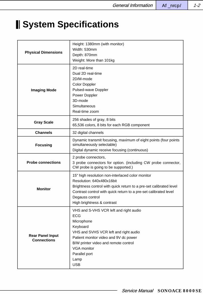
System Specifications
Physical Dimensions
Height: 1380mm (with monitor)Width: 530mm Depth: 870mmWeight: More than 101kg
Imaging Mode
2D real-timeDual 2D real-time2D/M-modeColor DopplerPulsed-wave DopplerPower Doppler3D-modeSimultaneousReal-time zoom
Gray Scale256 shades of gray, 8 bits65,536 colors, 8 bits for each RGB component
Channels 32 digital channels
FocusingDynamic transmit focusing, maximum of eight points (four points simultaneously selectable)Digital dynamic receive focusing (continuous)
Probe connections2 probe connectors,3 probe connectors for option. (including CW probe connector, CW probe is going to be supported.)
Rear Panel Input Connections
VHS and S-VHS VCR left and right audioECG MicrophoneKeyboardVHS and SVHS VCR left and right audioPatient monitor video and 9V dc powerB/W printer video and remote controlVGA monitor Parallel portLampUSB
Monitor
15" high resolution non-interlaced color monitorResolution: 640x480x16bitBrightness control with quick return to a pre-set calibrated levelContrast control with quick return to a pre-set calibrated levelDegauss controlHigh brightness & contrast

Service Manual SONOACE 8000SE
General Information Chapter 1 1-3
Image StorageCine loop memory (maximum 256 frames)Image filing system
Application
AbdominalObstetricalPeripheral vascularGynecological and fertilitySmall parts (breast, thyroid, parathyroid, penis, testes) Abdominal surgeryRenalBreastMusculoskeletalPediatricProstateUrologyTrans-RectalTrans-Vaginal
Electrical Parameters 100-120V/200-240VAC, 12.5/10A, 50/60Hz
VOLUME MODE
Freehand 3DOptimal volume resolutionVarious 3D rendering algorithm
- Surface mode- Maximum transparent mode- Minimum transparent mode- X-ray mode
MagiCut Plus3D Orientation Help
Harmonic mode Harmonic/Pulse Inversion
FRAME RATE Max. up to about 100 fps
TIME GAIN COMPENSATION
Eight – Slide Pot ControlsReassigned on HRZ, Depth and U/D Invert Adjustments
DEPTH SELECTION From 2 to 24 cm
DOCUMENTATION CAPABILITIES
On-board VCR controlsOn-board printing device controlSelective printing on two connected printersSonoView LiteDICOM 3.0

Service Manual SONOACE 8000SE
Optional Devices
Video Cassette Recorder (VCR)• Panasonic AG-MD 830 SVHS (NTSC & PAL)Video Page Printer• Mitsubishi M90E B/W page printer(120V/240V, NTSC/PAL, 3" x 4" format)Color Video Page Printer• Mitsubishi CP700U color page printer (120V NTSC)• Mitsubishi CP700E color page printer (240V PAL)Foot SwitchThe functions of Left & Right Foot Pedals can be selected in Setup Mode.Freeze, Update, Record, Print, Store, 3D, ECG Trigger On/Off
Measurement
Trackball operation of multiple cursors2D: Linear measurements and area measurements using elliptical approximation or traceM-mode: Continuous readout of distance, time, and slope rate Doppler: Velocity and trace
Peripheral Signals
RGB Sync (Out)• NTSC/PAL• Red: 1.0 Vpp / 75 ohms• Green: 1.0 Vpp / 75 ohms• Blue: 1.0 Vpp / 75 ohms• Composite Sync: TTLS –VHS (In/Out)• NTSC/PAL• Chrominance: 0.286Vpp/75 ohms/unbalanced• Luminance: 1.0Vpp/75 ohms/unbalancedVHS (In/Out)• NTSC/PAL• 1.0 Vpp/75ohms/unbalancedVideo Patient Monitor (Out)• Video Signal • NTSC/PAL• 1.22Vpp/75ohms/unbalancedAudio R/L(In/Out) : portsVGA(Out) : 2 portsRS-232C(In/Out) : 1 port (COM1)DICOM(In/Out) : 2 ports 10-Base TypeUSB port(In/Out) : 2 ports (Ver. 1.0)Microphone(In) : 1 portPrinter B/W(Out) : 1.0Vpp/75 ohms/unbalancedPrint Remote(Out) : Echo printer trigger
General Information Chapter 1 1-4

Service Manual SONOACE 8000SE
General Information Chapter 1 1-5
Signal processing(Pre-processing)
TGC control Mode-independent gain controlAcoustic power control (adjustable)Dynamic apertureDynamic apodizationDynamic range control (adjustable)Image view area controlM-mode sweep speed control
Signal processing(Post-processing)
Frame average Gamma-scale windowingImage orientation (left/right and up/down)White on black/black on whiteReal-time zoom
Auxiliary
Black-and white printerColor printerVCRMonitorFoot switch
Pressure LimitsOperating: 700hPa to 1060hPaStorage: 700hPa to 1060hPa
Humidity LimitsOperating: 30% to 75%Storage & Shipping: 10% to 95%
Temperature LimitsOperating: 10 OC ~ 35OCStorage & Shipping: -40OC ~ 70OC
CPU module
Main host CPU: CPU card including Geode processor, Hard drive: 80 GBRAM size: 128MBytesLinux based OSVGA/LAN/Sound functions, and Interfacing function toCD R/W (Optional)

Service Manual SONOACE 8000SE
Scan Heads
<Convex Array>C3-7ED Probe• Application: General, Abdomen, Fetal Heart, Gynecology,
Obstetrics, Renal• Number of element: 128• Center frequency: 4.5MHz• Convex of radius: 50mm• FOV: 69.56°• Doppler TX frequency: 2.8MHz• Harmonic frequency: 2.2MHzBiopsy guide available
<Linear Array>HL5-9ED Probe• Application: General, Breast, Small Part, Vascular,
Muscuoskeletal• Number of element: 128• Center frequency: 7.5MHz• FOV: 38.4mm• Doppler TX frequency: 5.6MHz• Steered angle: 15°• Trapezoidal imaging• Biopsy guide available
<Endocavity Curved Linear Array>EC4-9ED Probe• Application: General, Obstetrics, Gynecology, Urology• Number of element: 128• Center frequency: 6.5MHz• Convex of radius: 19.4mm• FOV: 150.34°• Doppler TX frequency: 5.13MHz• Biopsy guide available
General Information Chapter 1 1-6

Service Manual SONOACE 8000SE
System Configurations
The SA8000SE system comprises a main body, control panel, probe and peripheral devices.
The main body is divided into the inner part that generates ultrasound images and the outer part, which connects to the other units. The outer part is equipped with probe connectors, connectors for monitor and the other peripheral devices, input-output devices like HDD, probe holders, wheels for moving, storage space for peripheral devices and a system power switch.
[Figure 1-1] Main Body
Main BodyMain Body
General Information Chapter 1 1-7

Service Manual SONOACE 8000SE
The control panel is the unit for users to operate the system.The control panel is largely primarily divided into three parts. On the left side there are function keys to control menu, scan and control the ultrasound image. On the central part, the function keys for measurement and annotation after image scanning are arranged around a trackball. On the right side you can find the function keys to select menu. And On the Alpha-Numeric keyboard there are manage an image and setup.
[Figure. 1-2] Control Panel
SlideSlide increases a value if it is pushed to the right and decreases a value if pushed to the left. The TGC Slide is an example.
ButtonAs one of most general controls, you have only to press the button to start a desired operation. The [Set] button is an example. This is a button worked by toggle. That is, one press of button turns the function on, and one more press of button turns the function off.
Control PanelControl Panel
Kinds of Controls and the OperationsKinds of Controls and the Operations
General Information Chapter 1 1-8

Service Manual SONOACE 8000SE
General Information Chapter 1 1-9
TrackballThe trackball is a control to move a cursor on the screen.
Dial-Button The dial-button is designed to add to the convenience of use and to reduce the complexity of the control panel. It also functions as a dial, which changes a value by turning to the left or right, and as a button, which operates by pressing. The [Menu] dial-button is an example. This dial-button is to execute the currently selected menu item. Turning the dial-button to the right, you can select the upper menu items of the current menu. Turning to the left, you can select the lower menu items.
DialThe dial is the control that increases or decreases the value upon turning to the right or left, respectively. The [Gain] dial is an example.
Up-Down SwitchThe up-down switch is a control that increases a value while it is up and decreases a value while it is down. The [Scale] switch is an example. When you switch it up or down, the focusing point ascends or descends, respectively.

Service Manual SONOACE 8000SE
[Figure 1-3] Controls on the Control panel
Control on the Control PanelControl on the Control Panel
General Information Chapter 1 1-10
Freeze This button is to turn the image scanning on or off. In freeze state, Cine function, saving, printing out and measuring the image are available.
StoreThis button stores the image or report that are currently being displayed on the screen in the system database. The stored images and Report can be controlled in SonoView mode.
Echo PrintThis button prints out the image viewed on the current Image Area into a configured echo printer.

Service Manual SONOACE 8000SE
2D
In 2D mode, it is possible to examine organs in direction of the depth of scanning in real time. Because this system includes 2D image basically, except for some special cases, you cannot turn the 2D off when desired. Therefore, the [2D] button does not work as a toggle although it gives LED feedback. Instead, it is used as a button to return to the basic 2D mode even from any other image modes.a
M
This button is to turn the M Mode on. It is possible to observe one desired line of 2D images as time goes by. While the M Mode is on, one more press of this button turns it off.
C
This button is to turn the Color Mode on. Patterns of bloodstream are shown in 2D screen in real time. While the color mode is on, one more press of this button turns it off.
D
This button is to turn the PW Spectral Doppler Mode on. It is possible to observe blood vessel or bloodstream of heart. Spectral Doppler also can be used with 2D mode at the same time. While the PW Spectral Doppler Mode is on, one more press of this button turns it off.
PD
This button is to turn the Power Doppler Mode on. While the Power Doppler Mode is on, one more press of this button turns it off.
Dual
This button turns the Dual Mode on. You can compare two 2D images in Dual mode. While the dual mode is on, one more press of this button turns it off. You can use the [Set] button or [Dual] button to change the left/right view direction of the activated image in Dual Mode.
Image Mode & Gain ControlImage Mode & Gain Control
General Information Chapter 1 1-11

Service Manual SONOACE 8000SE
Harmonic
This button is to turn the Harmonic Imaging on. While the harmonic imaging is on, one more press of this button turns it off. This is applicable to the 2D Harmonic Imaging.
CW
This button is to turn the CW Spectral Doppler mode on. While the CW Spectral Doppler Mode is turned on, one more press of button turns it off.
B Gain
This dial is used to control 2D Gain by turning it.
C Gain
This dial is used to control color Gain by turning it. In the PD mode, you can also control PD gain by turning this dial.
D Gain
This dial is used to control Doppler Gain by turning it.
Focus
If this switch is up, the focusing point goes up. Conversely, when switch is down the focusing point goes down.
General Information Chapter 1 1-12

Service Manual SONOACE 8000SE
Depth
If this switch is up, the depth of image is shallow. Conversely switch-down results in a deeper image.
HD Zoom
If you put up this switch, a Zoom box appears. Change the Zoom size by using the [Change] button and trackball. And then press [Set] button to apply to image.You can exit from Zoom mode by pressing the [Exit] button or controlling [Depth] switch.
Zoom
This button is for Read Zoom function. You can control the size and the position of 2D image by using [Change] button and track ball. If you roll trackball upward, you can check the lower part of image and roll it downward, you can check the upper part of image. If you roll trackball leftward, you can check the right part of image and roll it rightward, you can check the left part of image.You can exit the Zoom mode by pressing the [Exit] button or [Zoom] button.
Frequency
This button is to change the probe frequency, when you use a probe that supports Multi Frequency. You can select the frequency of probe by pressing this button several times. The meanings are below.
Audio
This slide is to control the sound volume in Spectral Doppler Mode.
GEN General frequency
RES High frequency
PEN Low frequency
Color & Doppler Image ControlsColor & Doppler Image Controls
General Information Chapter 1 1-13
Service Manual SONOACE 8000SE
General Information Chapter 1 1-14
Angle
This dial is to control the angle of Sample Volume in Spectral Doppler Mode. It is also used to
Baseline
This switch is to control the Baseline in Spectral Doppler Mode or Color Doppler Mode. Baseline ascends with switch-up and descends with switch-down.
Speed
This button is to control the Sweep Speed in Spectral Doppler Mode or M Mode. If you press this button, the sweep speed changes step by step.
Scale
This switch is to control the speed of blood flow or frequency range in Color Doppler Mode, Spectral Doppler Mode or Power Doppler Mode. Switch-up expands the range of speed (frequency) and switch-down reduced the range of speed (frequency).
Filter
This switch is to control the Wall Filter values in Color Doppler Mode, Power Doppler Mode or Spectral Doppler Mode. Switch-up increases the Wall Filter values and switch-down decreases the values.
Invert
This button is to invert the top and the bottom of the color bar in Color Doppler Mode. It also inverts the top and the bottom of the speed (frequency) axis in Spectral Doppler Mode
Steer
This button is to alter the angle of ROI (Region of Interest) in Color Doppler Mode or Power Doppler Mode. This operation is only available for Linear Probe. This button changes ROI to the left, the front and then to the right in this order.

Service Manual SONOACE 8000SE
General Information Chapter 1 1-15
TGC ControlTGC Control
You can control the TGC values by depth using six slides.
While controlling the TGC slides, if you make the Gain difference of two adjacent slides too big, there might appear a line on the image. Therefore it is not advisable for a user to control the slides in that way.
Caution
Measurement and Annotation controlsMeasurement and Annotation controls
These are used to measure the image for diagnosis and to annotate it after obtaining the desired image.
aliper
This button is to measure distance, volume, circumference and area. Select measurement methods such as Distance, Ellipse, Trace, Hip Joint, and Volume. If you press this button repeatedly, you can select desired measure method among all the ones supported.
Also, by pressing this button, measure menu appears at Flexible soft menu. Since each measure menu has more than 2 measure methods, Flexible press soft menu button repeatedly to select your desired measure method. Refer to “Chapter 7. Basic Measurements”.
Calculator
This button is to display some menus that can be possibly measured in the selected Application or Image Mode. Hence you can measure any desired item from the menu. Refer to “Chapter 8. Measurements by applications”.
Body Marker
This button is to display the list of Body markers. If you select a desired marker, you can insert the Body marker into the image on the screen.

Service Manual SONOACE 8000SE
Indicator
This button is to display an arrow-shaped indicator, so that you can mark the image with the indicator.
Text
This button is to input a text on the image.
Clear
This button is to delete Text, Indicator, Body Mark, and measurement results on the image.
Trackball
Trackball makes cursor move on the screen. It also searches the image in Cine mode.
Change
Trackball makes cursor move on the screen. It also searches the image in Cine mode.
Exit
This button is to exit a current state of the system and return to a default mode.
Controls related to trackball operation.
Measurement and Annotation controlsMeasurement and Annotation controls
General Information Chapter 1 1-16
Service Manual SONOACE 8000SE
General Information Chapter 1 1-17
Set/Update
This button is to set up the item or value that you have selected using trackball.
In diagnosis mode, this button carries out options, which are available. For example, it is used to change the left/right view direction of the activated image in dual mode. When you press this button once, the scanning image is appeared in right side. If you press the button one more time, the image in the right side will be frozen and the scanning image is appeared in left side. In Spectral Doppler mode, it is used to hold or scan 2D image. For measurement, Press this when you complete one measurement and desire one more, and cursor with other shape will appear.
Menu ControlMenu Control
Controls related to the menu displayed on the screen.
Menu This dial-button is to execute the currently selected menu item. Turning the dial-button to the right, you can select the upper menu items of the current menu. Turning to the left, you can select the lower menu items.
3D Control3D ControlControls related to diagnosis using 3D image.
3D The [3D ] button on the alphanumeric keyboard is to display 3D.While the 3D Image Mode is on, one more press of this button turns it off. 3D mode is unable in Cine mode or not in 2D mode.
Service Manual SONOACE 8000SE
General Information Chapter 1 1-18
Utility ControlsUtility Controls
Controls related to all kinds of utilities supported by SA8000SE.
UtilityThe [Utility ] button on the alphanumeric keyboard is to display utility menu.
SonoViewThe [SonoView ] button on the alphanumeric keyboard is to operate SonoView, which is an Image Filing program.
Report
The button on the alphanumeric keyboard is to display one of the Report programs, which includes measurement results of the currently selected Application.
Setup ControlsSetup Controls
Controls related to various setups of the system.
ProbeThis button is to display a window to select or change the probe and Application.
SetupThe [Setup ] button on the alphanumeric keyboard is to display a Setup window to setup the parameters related to the system.
PatientThis button is to display the window to select a patient or input new information of patient.
End ExamThis button is to finish the diagnosis on the current patient and reset the related data.

Service Manual SONOACE 8000SE
General Information Chapter 1 1-19
Alpha numeric KeyboardAlpha numeric Keyboard
[Figure 1-4] Alphanumeric keyboards
It is used to input a text and so on. The buttons from 1 to 5 function as Flexible soft buttons in the diagnosis mode. Some function keys are used for measurement
Measurement buttons in the Keyboards
These are for OB measurements. You can measure immediately only what you select.
Flexible Soft Button Control
These buttons on the alphanumeric keyboard is to execute the corresponding Soft Menu on the lower part of screen according to the state of the system.
X KEY
During using VCR, you can exit from VCR by pressing X key.

Service Manual SONOACE 8000SE
A color VGA monitor is provided, to display ultrasound images and other information.The monitor is connected with the Main Body along with an axis, freely movable in any direction.
The probe generates ultrasound waves and obtains constitutive data for ultrasound images.Refer to “Chapter 12. Probes” for further information.
Peripheral devices like VCR, Echo-printer, Microphone, Foot Switch or lamp are connected tothe main body.
MonitorMonitor
ProbeProbe
Peripheral DevicesPeripheral Devices
General Information Chapter 1 1-20

Service Manual SONOACE 8000SE
The monitor screen of this system displays ultrasound images, diverse information and user operation menus. As shown below, the screen configuration is mainly divided into Title, Image Area, Menu, Feedback Area and Flexible Soft Menu.
[Figure 1-5] Screen Configurations
The Title displays Logo, Patient Information, Name of hospital, Application, Frame Rate and Depth, Probe Information, Acoustic Output Information, Date and Time.
Screen Configurations
TitleTitle
General Information Chapter 1 1-21

Service Manual SONOACE 8000SE
General Information Chapter 1 1-22
Logo
The Medison Logo is displayed here.
Patient InformationThe Patient’s ID and name are displayed here. The patient’s information can be given in the patient information window.
Name of Hospital and ApplicationThe name of the hospital and the selected application are displayed. The name of the
hospital can be set in the system setup window, and the application can be selected in the probe selection window.
Frame Rate and DepthThe Frame rate and the present diagnosis depth are displayed. The frame rate depends
on the diagnosis mode. In image control menu, you can change the frame rate. The [Depth] switch on the control panel is used to adjust the diagnosis depth.
Probe InformationThe Name of the probe and its frequency information are displayed. You can select the
type of probe in the probe selection window. The probe frequency can be changed by pressing the [FREQ] button on the control panel. A general or normal frequency is shown as ‘GEN,’ the higher and lower frequencies are shown as ‘RES’ and ‘PEN’, respectively.
Acoustic Output InformationMI (Mechanical Index) and TI (Thermal Index) are displayed.
Date and TimeThe Date and Time currently set up in the system are displayed. You can change the date
and time using the system setup window.

Service Manual SONOACE 8000SE
General Information Chapter 1 1-23
Image AreaImage Area
The ultrasound image, image information, annotation and measurement information are displayed on the image area.
[Figure. 1-6] Image Area
Ultrasound ImageIt is an ultrasound image scanned using a probe. The image format depends on the diagnosis
mode. On the left side of the image, certain markers are displayed like depth marker, focus marker and gray or color index bar.
Image InformationThe information on the ultrasound images such as Gain, Dynamic Range and so on are
displayed. The contents of the image information depend on the kinds of ultrasound image currently displayed.
AnnotationAnnotation is displayed to explain the image. This includes Body mark, Indicator and Text.
Measurement InformationThe basic measures of distance, circumference, area and volume are displayed together with the
measurement results from various Applications.

Service Manual SONOACE 8000SE
General Information Chapter 1 1-24
These consist of Image Control Menu, Measure Menu and Utility Menu.
MenusMenus
Image Control Menu
[Figure 1-7] Image Control Menu – 2D mode
When you use [Menu] dial-button, Image control menu is displayed on the right side of screen. If the diagnosis mode is changed, a different menu is displayed. You can select the corresponding menu turning the [Menu] dial-button on the control panel.
Measure Menu
[Figure 1-8] Measure Menu - OB
A different Measure Menu is provided for each Application, and displayed by pressing the [Calculation] button on the control panel. You can select Measure Menu using the [Menu] dial-button or trackball on the control panel.

Service Manual SONOACE 8000SE
General Information Chapter 1 1-25
Utility MenusThe Utility Menu is used for the operation of various utilities and system setup. It is displayed when the [Utility ] button on the alphanumeric keyboards is clicked. You can also select the Utility Menu using the [Menu] dial-button on the control panel.
[Figure 1-9] Utility MenusFeedback Area
[Figure 1-10] Body mark Feedback
The Feedback area shows you all information required for system operation. The feedback area displays the current state of the system and the item that can be selected.
Flexible Soft Menus
Flexible Soft Menu is always displayed on the screen. Displayed items depend on the system state.
[Figure 1-11] Flexible Soft Menus

Service Manual SONOACE 8000SE
General Information Chapter 1 1-26
Option functions
SA8000SE has the following optional functions that can be provided according to you or
perator’s selection.
reehand 3D
It makes Surface Rendering - 3D image, which is from 2D image, by Volume Rendering
ethod. It is showed in 3D View.
onoView
his is the image-filing package by which you can store and manage the scanned images easily.
ICOM
DICOM is the abbreviation of Digital Imaging and Communications in Medicine.
his is the industrial standard for communication of images and other information between
edical devices on network. Using DICOM option, you can send or print images after
onnecting your ultrasound equipment and PACS.
For more detailed information on the above optional functions, refer to the relevant chapters in
is operation manual.

Service Manual SONOACE 8000SE
Chapter 2
Safety
Safety Specifications
Safety Instructions
Symbols
Electrical Safety
System organization
Environmental Protection
Equipment Protection
Safety for USB device
2-1
2-2
2-3
2-5
2-9
2-20
2-21
2-22
Service Manual SONOACE 8000SE
Safety RequirementsClassification:Class I equipment with Type BF applied partsOrdinary EquipmentNon-AP/APG
Electromechanical safety standards met: IEC/EN 60601-1 Medical Electrical Eqiupment, Part 1General Requirements for Safety.IEC/EN 60601-1-1 Safety requirements for medicalelectrical systems.IEC/EN 60601-1-2 Electromagnetic compatibility -Requirements and tests.IEC 61157 Declaration of acoustic output parameters.ISO 10993-1 Biological evaluation of medical devices.UL 2601-1 Medical Electrical Equipment, Part 1 General Requirements for Safety.CSA 22.2, 601.1 Medical Electrical Equipment, Part 1 General Requirements for Safety.
SafetySafety
Safety Chapter 2 2-1

Service Manual SONOACE 8000SE
Safety SignsPlease read this chapter before using an MEDISON ultrasound system. It applies to the ultrasound system, probes, recording devices, and any optional equipment.
SA8000SE is intended for use by, or by the order of, and under the supervision of a licensed physician qualified to direct the use of the device.
Safety signs in This manual are classified like below.
It describes the precautions necessary to prevent user hazards of great urgency. If a DANGER is ignored, it might cause users a fatal injury such as loss of life.
It is used to indicate the presence of a hazard that can cause serious personal injury, or substantial property damage if a WARNING is ignored.
It is used to indicate the presence of a hazard that can cause equipment damage if a CAUTION is ignored.
It is a piece of information not related to any hazard, but useful in installing, operating and maintaining the system.
Warning
Danger
Caution
Note
Safety Chapter 2 2-2

Service Manual SONOACE 8000SE
The international Electro technical Commission (IEC) has established a set of symbols for medical electronic equipment, which classify a connection or warn of potential hazards. The classifications and symbols are shown below.
Isolated patient connection (Type BF applied part).
Power switch (It supplies/cuts the power for product)
OFF (It cuts the power for some part of product)
ON (It supplies the power for some part of product)
This symbol identifies a safety note. Be sure you understand the function of this control before using it. The control function is described in the appropriate operation manual.
Identifies equipotential ground.
Indicates dangerous voltage over 1000 VAC or over 1500 VDC.
Identifies the point where the system safety ground is fastened to the chassis. Protective earth connected to conductive parts of Class I equipment for safety purposes.
Output port for VGA or Parallel port
ECG port
Isolated patient connection (Type BF applied part).
Power switch (It supplies/cuts the power for product)
Symbols
Safety Chapter 2 2-3

Service Manual SONOACE 8000SE
Safety Chapter 2 2-4
Input/Output (I/O) port used for RS232C
Left and right Audio / Video input
Left and right Audio / Video output
Print remote output
Foot switch connector
ECG connector
USB connector
MIC input port
Protection against the effects of immersion.

Service Manual SONOACE 8000SE
This equipment has been verified as a Class I device with Type BF applied part. For maximum safety observe these warnings:
Shock hazards may exist if this system, including all externally mounted recording and monitoring devices, is not properly grounded.
In a hospital, doctors and patients are subjected to dangerous, uncontrollable compensating currents. These currents are due to the potential differences between connected equipment and touchable conducting parts as found in medical rooms. The safe solution to the problem is accomplished with consistent equipotential bonding. Medical equipment is connected with connecting leads made up with angled sockets to the equipotential bonding network in medical rooms.
Safety Chapter 2 2-5
Electrical Safety
Warning
Main Body
Equipotential TerminalConnection Lead
(Socket)
EquipotentialConnector
Earth in Medical Room
Do not remove the protective covers on the system; hazardous voltages are present inside. Cabinet panels must be in place while the system is in use. All internal adjustments and replacements must be made by a qualified Medison Customer Service Department.
Do not operate this system in the presence of flammable gases oranesthetics. Explosion can result.
Warning

Service Manual SONOACE 8000SE
Safety Chapter 2 2-6
To avoid risk of electrical shock hazards, always inspect all the probes before use; check the face, housing, and cable before use. Do not use, if the face is cracked, chipped, or torn, the housing is damaged, or the cable is abraded.
To avoid risk of electrical shock hazards, always disconnect the system from the wall outlet prior to cleaning the system.
All patient contact devices, such as probes, ECG leads must be removed from patient contact prior to application of a high voltage defibrillation pulse.
To avoid risk of electrical shock, do not use any probe that has been immersed beyond the specified cleaning or disinfection level. See ‘Chapter 11. Maintenance’ in this manual.
Conductive parts of electrodes shall not contact other conductive parts including earth.
To avoid risks of electrical shock and fire hazards, inspect the system power cord and plug on a regular basis. Ensure that they are not damaged in any way.
To avoid risk of electrical shock hazards, accessory equipment connected to the along the digital interfaces must be certified according to the representative IEC standards (I.e. IEC60950/EN60950 for data processing equipment and IEC60601-1/EN60601-1 for medical equipment). Furthermore all configurations shall comply with the system standard IEC60601-1-1/EN60601-1-1. Everybody who connects additional equipment to the signal input part or signal output part configurations a medical system, and is therefore responsible that the system complies with the requirement of IEC60601-1-1/EN60601-1-1. If in doubt, consult the Medison Customer Service Department.
Do not touch the SIP/SOP and patient simultaneously. It may cause a leakage current exceeding the maximum allowable values.Do not perform any changes or repairs on the ECG-amplifier, the connecting cables or the patient cable. A defective patient cable must be exchanged. Only authorized service personnel must perform necessary repairs.
Warning
This device is not intended to provide a primary ECG monitoring function, therefore, does not have means of indicating an inoperative electrocardiograph.
Do not use ECG electrodes for HF surgical equipment. It can cause the hazard of burns in the event of defect in HF surgical equipment.
Do not use ECG electrodes during the operation of a cardiac pacemaker or other electrical stimulators. It can cause any safety hazard to a patient.Do not use ECG leads and electrodes in an operating room.
Warning
Service Manual SONOACE 8000SE
Safety Chapter 2 2-7
■ Although your system has been manufactured in compliance with existing EMI/EMC requirements, use of this system in the presence of an electromagnetic field can cause momentary degradation of the ultrasound image. If this occurs often, MEDISON suggests a review of the environment in which the system is being used, to identify possible sources of radiated emissions. These emissions could be from other electrical devices used within the same room or an adjacent room. Communication devices such as cellular phones and pagers can cause these emissions. The existence of radio, TV, or microwave transmission equipment located nearby can cause emissions. In cases where EMI is causing disturbances, it may be necessary to relocate your system.■ E lectrostatic discharge (ESD), commonly referred to as a static shock, is a naturally occurring phenomenon. ESD is most prevalent during conditions of low humidity, which can be caused by heating or air conditioning. During low humidity conditions, electrical charges naturally build up on individuals and can create static shocks. An ESD condition occurs when an individual with an electrical energy build-up comes in contact with objects such as metal doorknobs, file cabinets, computer equipment, and even other individuals. The static shock or ESD is a discharge of the electrical energy build-up from a charged individual to a lesser or non-charged individual or object. The level of electrical energy discharged from a system user or patient to the ultrasound system can be significant enough to cause damage to the system or probes. The following precautions can help to reduce ESD: anti-static spray on carpets; anti-static spray on linoleum; anti-static mats; or a ground wire connection between the system and the patient table or bed.
Caution

Service Manual SONOACE 8000SE
Guidance and manufacturer’s declaration - electromagnetic immunity
EMC Test ReportsEMC Test Reports
The EUT is intended for use in the electromagnetic environment specified below.The customer or the user of the EUT should assure that it is used in such an environment.
Immunity test IEC 60601Test level Compliance level Electromagnetic
environment -guidance
Electrostatic discharge (ESD)
IEC 61000-4-2
±6kV Contact
±8kV air
±6kV Contact
±8kV air
Floors should be wood, concrete or ceramic tile. If floors are covered with synthetic material, the relative humidity should be at least 30%.
Electrical fasttransient/burst
IEC 61000-4-4
±2kV for powersupply lines± 1kV for input/output lines
±2kV for powersupply lines± 1kV forinput/output lines
Mains power quality should be that of a typical commercial or hospital environment.
Surge
IEC 61000-4-5
±1kV differential mode±2kV common mode
±1kV differential mode±2kV common mode
Mains power quality should be that of a typical commercial or hospital environment.
Voltage dips, short interruptions and voltage variations on power supplyinput lines
IEC 61000-4-11
<5% Uт(>95% dip in Uт)for 0.5cycle40% Uт(60% dip in Uт )for 5 cycle 70% Uт(30% dip in Uт)for 25 cycle<5% Uт(<95% dip in Uт )for 5 s
<5% Uт(>95% dip in Uт)for 0.5cycle40% Uт(60% dip in Uт )for 5 cycle 70% Uт(30% dip in Uт)for 25 cycle<5% Uт(<95% dip in Uт )for 5 s
Mains power quality should be that of a typical commercial or hospital environment. If the user of the EUT image intensifier requires continued operation during power mains interruptions, it is recommended that the EUT image intensifier be powered from an uninterruptible power supply or a battery.
Power frequency(50/60Hz)magnetic field
IEC 61000-4-8
3 A/m 3 A/m Powerfrequencymagnetic fields should be at levels characteristic of a typical location in a typical commercial or hospital environment.
NOTE Uт is the a.c. mains voltage prior to application of the test level.
Safety Chapter 2 2-8

Service Manual SONOACE 8000SE
Safety Chapter 2 2-9
System Organization
This section contains information about biological safety and a discussion of the prudent use of the system. A list of precautions related to biological safety follows; observe these precautions when using the system.
Do not use the system if an error message appears on the video display indicating that a hazardous condition exists. Note the error code, turn off power to the system, and call your local Customer Service Department of Medison.
Do not use a system that exhibits erratic or inconsistent updating. Discontinuities in the scanning sequence are indicative of a hardware failure that must be corrected before use.
Perform ultrasound procedures prudently. Use the ALARA (as low as reasonably achievable) principle.
Use only acoustic standoffs that have been approved for use by MEDISON.
The system limits the maximum temperature of contact as 41 degree Celsius, and the output of ultrasonic waves observes American FDA regulations respectively.
Power protection fuse prevents the probe and the system from current overflow. Should the power protection circuit sense any current overflow, the probe current will be shut off to prevent the probe surface from overheating; the output of ultrasound waves will be limited.
Warning
Warning
TE
Verify the alignment of the biopsy guide before use. See the “Chapter12. Probes” section of this manual.
Before cleaning probes, see the “Chapter12. Probes” section of this manual.
Note
Service Manual SONOACE 8000SE
Sheaths are recommended for clinical application of an invasive nature, including intraoperative, transrectal, transvaginal, and biopsy procedures. MEDISON does not supply sheaths so that you should purchase appropriate ones on your own.
Some sheaths contain natural rubber latex and talc, which can cause allergic reactions in some individuals, Refer to the FDA Medical Alert, March 29, 1991, reprinted here.
In neurosurgical applications, sterilized probes should be used with sterile gel and a sterile pyrogen-free sheath.
If the sterile sheath becomes compromised during neurosurgical applications involving a patient with Creutzfeldt-Jakob disease, the probe cannot be sterilized with any sterilization method.
Sheaths are disposable and must not be reused.
If an installed sheath is cut or contaminated prior to use, the probe should be cleaned and disinfected, and a new sterile sheath installed.
ALARA Education ProgramALARA Education Program
The guidance for the use of diagnostic ultrasound is defined by the “as low as reasonably achievable” (ALARA) principle. The decision as to what is reasonable has been left to the judgment and insight of qualified personnel. No set of rules can be formulated that would be sufficiently complete to dictate the correct response to every circumstances. By keeping ultrasound exposure as low as possible, while obtaining diagnostic images, users can minimize ultrasonic bioeffects.
Since the threshold for diagnostic ultrasound bioeffects is undetermined, it is the sonographer’sresponsibility to control total energy transmitted into the patient. The sonographer must reconcile exposure time with diagnostic image quality. To ensure diagnostic image quality and limit exposure time, an ultrasound system provides controls that can be manipulated during the exam to optimize the results of the exam.
The ability of the user to abide by the ALARA principle is important. Advances in diagnostic ultrasound not only in the technology but also in the applications of that technology, have resulted in the need for more and better information to guide the user. The output indices are designed to provide that important information
There are a number of variables, which affect the way in which the output display indices can be used to implement the ALARA principle. These variables include values, body size, location of the bone relative to the focal point, attenuation in the body, and ultrasound exposure time. Exposure time is an especially useful variable, because the user controls it. The ability to limit the index values over time supports the ALARA principle.
Warning
Safety Chapter 2 2-10

Service Manual SONOACE 8000SE
Applying ALARAThe system-imaging mode used depends upon the information needed. B-mode and M-mode imaging provide anatomical information, while Doppler, Power, and Color imaging provide information about blood flow. A scanned mode, like B-mode, Power, or Color, disperses or scatters the ultrasonic energy over an area, while an unscanned mode, like M-mode or Doppler, concentrates ultrasonic energy. Understanding the nature of the imaging mode being used allows the sonographer to apply the ALARA principle with informed judgment. Additionally, the probe frequency, system set-up values, scanning techniques, and operator experience allow the sonographer to meet the definition of the ALARA principle.
The decision as to the amount of acoustic output is, in the final analysis, up to the system operator. This decision must be based on the following factors: type of patient, type of exam, patient history, ease or difficulty of obtaining diagnostically useful information, and the potential localized heating of the patient due to probe surface temperatures. Prudent use of the system occurs when patient exposure is limited to the lowest index reading for the shortest amount of time necessary to achieve acceptable diagnostic results.
Although a high index reading does not mean that a bioeffect is actually occurring, a high index reading should be taken seriously. Every effort should be made to reduce the possible effects of a high index reading. Limiting exposure time is an effective way to accomplish this goal.
There are several system controls that the operator can use to adjust the image quality and limit the acoustic intensity. These controls are related to the techniques that an operator might use to implement ALARA. These controls can be divided into three categories: direct, indirect, and receiver control.
Direct ControlsApplication selection and the output intensity control directly affect acoustic intensity. There are different ranges of allowable intensity or output based on your selection. Selecting the correct range of acoustic intensity for the application is one of the first things that occur in any exam. For example, peripheral vascular intensity levels are not recommended for fetal exams. Some systems automatically select the proper range for a particular application, while others require manual selection. Ultimately, the user has the responsibility for proper clinical use. The Medison system provides both automatic or default and manual or user-selectable settings.
Output has direct impact on acoustic intensity. Once the application has been established, the output control can be used to increase or decrease the intensity output. The output control allows you to select intensity levels less than the established maximum. Prudent use dictates that you select the lowest output intensity that is consistent with good image quality.
Safety Chapter 2 2-11

Service Manual SONOACE 8000SE
Indirect ControlsThe indirect controls are those that have an indirect effect on acoustic intensity. These controls affect imaging mode, pulse repetition frequency, focus depth, pulse length, and probe selection.
The choice of imaging mode determines the nature of the ultrasound beam. B-mode is a scanning mode, Doppler is a stationary or unscanned mode. A stationary ultrasound beam concentrates energy in a single location. A moving or scanned ultrasound beam disperses the energy over an area and the beam is concentrated on the same area of a fraction of the time as that of an unscanned mode.
Pulse repetition frequency or rate refers to the number of ultrasound bursts of energy over a specific period of time. The higher the pulse repetition frequency, the more pulse of energy in a period of time. Several controls affect pulse repetition frequency: focal depth, display depth, sample volume depth, color sensitivity, number of focal zones, and sector width controls.
Focus of the ultrasound beam affects the image resolution. To maintain or increase resolution at a different focus requires a variation in output over the focal zone. This variation of output is a function of system optimization. Different exams require different focal depths. Setting the focus at the proper depth improves the resolution of the structure of interest.
Pulse length is the time during which the ultrasonic burst is turned on. The longer the pulse, the greater the time-average intensity value. The greater the time-average intensity, the greater the likelihood of temperature increase and cavitations. Pulse length or burst length or pulse duration is the output pulse duration in pulsed Doppler. Increasing the Doppler sample volume increases the pulse length.
Probe selection indirectly affects intensity. Tissue attenuation changes with frequency. The higher the probe operating frequency, the greater the attenuation of the ultrasonic energy. A higher probe operating frequency requires more output intensity to scan at a deeper depth. To scan deeper at the same output intensity, a lower probe frequency is required. Using more gain and output beyond a point, without corresponding increases in image quality, can mean that a lower frequency probe is needed.
Receiver ControlsReceiver controls are used by the operator to improve image quality. These controls have no effect on output. Receiver controls only affect how the ultrasound echo is received. These controls include gain, TGC, dynamic range, and image processing. The important thing to remember, relative to output, is that receiver controls should be optimized before output is increased. For example; before increasing output, optimize gain to improve image quality.
Safety Chapter 2 2-12
Service Manual SONOACE 8000SE
Additional ConsiderationsEnsure that scanning time is kept to a minimum, and ensure that only medically required scanning is performed. Never compromise quality by rushing through an exam. A poor exam require a follow-up, which ultimately increase time. Diagnostic ultrasound is an important tool in medicine, and, like any tool, it should be used efficiently and effectively.
Output Display FeaturesThe system output display comprises two basic indices: a mechanical index and a thermal index. The thermal index further consists of the following indices: soft tissue (TIs) and bone (TIb). One of these three thermal indices will be displayed at all times. Which one depends upon the system preset or user choice, depending upon the application at hand.
The mechanical index is continuously displayed over the range of 0.0 to 1.9, in increments of 0.1
The thermal index consists of the three indices, and only one of these is displayed at any one time.Each probe application has a default selection that is appropriate for that combination. The TIb or TIs is continuously displayed over the range of 0.0 to maximum output, based on the probe and application, in increments of 0.1.
The application-specific nature of the default setting is also an important factor of index behavior. A default setting is a system control state which is preset by the manufacturer or the operator. The system has default index settings for the probe application. The default settings are invoked automatically by the ultrasound system when power is turned on, new patient data is entered into the system database, or a change in application takes place.
The decision to display one or the other of the three thermal indices should be based on the following criteria:
Appropriate index for the application: TIs is used for imaging soft tissue; and TIb for a focus at or near bone.
Mitigating factors that might create artificially high or low thermal index readings: location of fluid or bone, or blood flow. For example, is there a highly attenuating tissue path so that the actual potential for local zone heating is less than the thermal index displays.
Probe modes versus unscanned modes of operation affect the thermal index. For scanned modes, heating tends to be near the surface; for unscanned modes, the potential for heating tends to be deeper in the focal zone.
Always limit ultrasound exposure time. Do not rush the exam. Ensure that the indices are kept to a minimum and that exposure time is limited without compromising diagnostic sensitivity.
Mechanical Index (MI) DisplayMechanical bioeffects are threshold phenomena that occur when a certain level of output is exceeded. The threshold level varies, however, with the type of tissue. The potential for mechanical bioeffects varies with peak pressure and ultrasound frequency. The MI accounts for these two factors. The higher the MI value, the greater the likelihood of mechanical bioeffectsoccurring. There is no specific MI value that means that a mechanical effect is actually occurring. The MI should be used as a guide for implementing the ALARA principle.
Safety Chapter 2 2-13

Service Manual SONOACE 8000SE
hermal Index (TI) Display
The TI informs the user about the potential for temperature increase existing at the surface
f the body, within the body tissue, or at the point of focus of the ultrasound beam on bone.
he TI is an estimate of temperature increase in body tissue with specific properties.
he actual amount of any temperature rise is influenced by factors such as tissue type,
ascularity, mode of operation and others. The TI should be used as a guide for
mplementing the ALARA principle.
he bone thermal index (TIb) informs the user about potential heating at or near the focus after the
ltrasound beam has passed through soft tissue or fluid, for example, at or near second or third
imester fetal bone.
he cranial bone thermal index (TIc) informs the user about the potential heating of bone at or near
he surface, for example, cranial bone.
he soft tissue thermal index (TIs) informs the user about the potential for heating within soft
omogeneous tissue.
ou can select either TIs or TIb using the TIs/TIb selection on the Miscellaneous system setups.
Ic is displayed when you select a transcranial application.
echanical and Thermal indices Display Precision and Accuracy
he MI and TI precision is 0.1 unit on the system.
he MI and TI display accuracy estimates for the system are given in the Acoustic Output Tables
anual. These accuracy estimates are based on the variability range of probes and systems,
nherent acoustic output modeling errors and measurement variability, as described below.
he displayed values should be interpreted as relative information to help the system operator
chieve the ALARA principle through prudent use of the system. The values should not be
nterpreted as actual physical values in interrogated tissue or organs. The initial data that is used to
upport the output display is derived from laboratory measurements based on the AIUM
easurement standard. The measurements are then put into algorithms for calculating the
isplayed output values.
any of the assumptions used in the process of measurement and calculation are conservative in
Safety Chapter 2 2-14

Service Manual SONOACE 8000SE
B-mode sizeNarrowing the sector angle may increase frame rate. This action will increase the TI. Pulservoltage may be automatically adjusted down with software controls to keep the TI below the system maximums. A decrease in pulser voltage will decrease MI.
ZOOMIncreasing the zoom magnification may increase frame rate. This action will increase the TI. The number of focal zones may also increase automatically to improve resolution. This action may change MI since the peak intensity can occur at a different depth.
PersistenceA lower persistence will decrease the TI. Pulser voltage may be automatically increased. An increase in pulser voltage will increase MI.
Focal no.More focal zones may change both the TI and MI by changing frame rate or focal depth automatically. Lower frame rates decrease the TI. MI displayed will correspond to the zone will the largest peak intensity.
FOCUSChanging the focal depth will change MI. Generally, higher MI value will occur when the focal depth is near the natural focus of the transducer.
Control affecting the indicesAs various system controls are adjusted, the TI and MI values may change. This will be most apparent as the POWER control is adjusted; however, other system controls will affect the on-screen output values.
POWERPower controls the system acoustic output. Two real-time output values are on the screen: a TI and a MI. They change as the system responds to POWER adjustments.In combined modes, such as simultaneous Color, B-mode and pulsed Doppler, the individual modes each add to the total TI. One mode will be the dominant contributor to this total. The displayed MI will be from the mode with the largest peak pressure.
Control Control EffrctsEffrcts
B mode Controls B mode Controls
Safety Chapter 2 2-15
Service Manual SONOACE 8000SE
Color SensitivityIncreasing the color sensitivity may increase the TI. More time is spent scanning the color image. Color pulses are the dominant pulse type in this mode.
Color Sector WidthNarrower color sector width will increase color frame rate and the TI will increase. The system may automatically decrease pulser voltage to stay below the system maximum. A decrease in pulservoltage will decrease the MI. If pulsed Doppler is also enabled then pulsed Doppler will remain the dominant mode and the TI change will be small.
Color Sector DepthDeeper color sector depth may automatically decrease color frame rate or select a new color focal zone or color pulse length. The TI will change due to the combination of these effects. Generally, the TI will decrease with increased color sector depth. MI will correspond to the peak intensity of the dominant pulse type, which is a color pulse. However, if pulsed Doppler is also enabled then pulsed Doppler will remain the dominant mode and the TI change will be small.
SCALEUsing the SCALE control to increase the color velocity range may increase the TI. The system may automatically adjust pulser voltage to stay below the system maximums. A decrease in pulservoltage will also decrease MI.
SEC WIDTHA narrower B-mode sector width in Color imaging will increase color frame rate. The TI will increase. MI will not change. If pulsed Doppler is also enabled, then pulsed Doppler will remain the dominant mode and the TI change will be small.
SpeedM-mode and Doppler sweep speed adjustments will not affect the MI. When M-mode sweep speed changes, TI changes.
Simultaneous and Update MethodsUse of combination modes affects both the TI and MI through the combination of pulse types. During simultaneous mode, the TI is additive. During auto-update and duplex, the TI will display the dominant pulse type. The displayed MI will be from the mode with the largest peak pressure.
Sample Volume DepthWhen Doppler sample volume depth is increased the Doppler PRF may automatically decrease. A decrease in PRF will decrease the TI. The system may also automatically decrease the pulservoltage to remain below the system maximum. A decrease in pulser voltage will decrease MI.
Color and Color and CintrolsCintrols
MM--mode and Doppler Controlsmode and Doppler Controls
Safety Chapter 2 2-16

Service Manual SONOACE 8000SE
When a new imaging mode is selected, both the TI and MI may change to default settings. Each mode has a corresponding pulse repetition frequency and maximum intensity point. In combined or simultaneous modes, the TI is the sum of the contribution from the modes enabled and MI is the MI for the focal zone and mode with the largest derated intensity. The system will return to the previously selected state if a mode is turned off and then reselected.
ProbeEach probe model available has unique specifications for contact area, beam shape, and center frequency. Defaults are initialized when you select a probe. MEDISON factory defaults vary with probe, application, and selected mode. Defaults have been chosen below the FDA limits for intended use.
DEPTHAn increase in B-mode depth will automatically decrease the B-mode frame rate. This would decrease the TI. The system may also automatically choose a deeper B-mode focal depth. A change of focal depth may change the MI. The MI displayed is that of the zone with the largest peak intensity.
ApplicationAcoustic output defaults are set when you select an application. Medison factory defaults vary with probe, application, and mode. Defaults have been chosen below the FDA limits for intended use.
DOPPLER, MDOPPLER, M--MODE, and COLOR Imaging ControlsMODE, and COLOR Imaging Controls
Acoustic Output and Measurement Acoustic Output and Measurement
Since the initial use of diagnostic ultrasound, the possible human biological effects (bioeffects) from ultrasound exposure have been studied by various scientific and medical institutions. In October 1987, the American Institute of Ultrasound in Medicine(AIUM) ratified a report prepared by its Bioeffects Committee(Bioeffects Considerations for the Safety of Diagnostic Ultrasound, J Ultrasound Med., Sept. 1988: Vol.7, No.9 Supplement), sometimes referred to as the Stowe Report, which reviewed available data on possible effects of ultrasound exposure. Another report “Bioeffects and Safety of Diagnostic Ultrasound,” dated January 28, 1993 provides more current information.
The acoustic output for this system has been measured and calculated in accordance with the December 1985 “510(K) Guided for Measuring and Reporting Acoustic Output of Diagnostic Ultrasound Medical Devices,” except that the hydrophone meets the requirements of “Acoustic Output Measurement Standard for Diagnostic Ultrasound Equipment” (NEMA UD 2-1992)
Safety Chapter 2 2-17

Service Manual SONOACE 8000SE
ll intensity parameters are measured in water. Since water does not absorb acoustic energy, these
ater measurements represent a worst case value. Biological tissue does absorb acoustic
nergy.The true value of the intensity at any point depends on the amount and type of tissue and
he frequency of the ultrasound that passes through the tissue. The intensity value in the tissue. The
ntensity value in the tissue, In Situ, has been estimated by using the following formula:
n Situ = Water [ ]
here: In Situ = In Situ Intensity Value
Water = Water Value Intensity
e = 2.7183
a = Attenuation Factor
Tissue a(dB/cm-MHz)
Brain .53
Heart .66
Kidney .79
Liver .43
Muscle .55
= skin line to measurement depth (cm)
= Center frequency of the transducer/system/mode combination(MHz)
ince the ultrasonic path during an examination is likely to pass through varying lengths and types
f tissue, it is difficult to estimate the true In Situ intensity. An attenuation factor of 0.3 is used for
eneral reporting purpose; therefore, the In Situ value which is commonly reported uses the
ormula:
n Situ (derated) = Water [ ]
ince this value is not the true In Situ intensity, the term “derated” is used.
he maximum derated and the maximum water values do not always occur at the same
)23.0( alfe−
)069.0( lfe−
Safety Chapter 2 2-18

Service Manual SONOACE 8000SE
Acoustic Output and MeasurementAcoustic Output and Measurement
The terms and symbols used in the acoustic output tables are defined in the following paragraphs.
ISPTA.3 the derated spatial-peak temporal-averge intensity(milliwatts per square centimeter).
ISPPA.3 the derated spartial-peak pulse-average intensity(watts per square centimeter). The value of IPA.3 at the position of globalmaximum MI (IPA.3@MI) may be reported instead of ISPPA.3 if the globalmaximum MI is reported.
MI the Mechanical Index. The value of MI at the position of ISPPA.3,([email protected]) may be reported instead of MI(global maximum value)if ISPPA.3 is □190W/cm2
Pr.3 the derated peak rarefactional pressure (megapascals) associated with thetransmit pattern giving rise to the value reported under MI.
WO the ultrasonic power (milliwatts). For the operating condition giving rise toISPTA.3, WO is the total time-average power; for the operating conditionsubject to reporting under ISPPA.3, WO is the ultrasonic power associatedwith the transmit pattern giving rise to the value reported under ISPPA.3
fC the center frequency (MHz). For MI and ISPPA.3, fC is the center frequencyassociated with the transmit pattern giving rise to the global maximum valueof the respective parameter. For ISPTA.3, for combined modes involvingbeam types of unequal center frequency, fC is defined as the overall range ofcenter frequencies of the respective transmit patterns.
ZSP the axial distance at which the reported parameter is measured(centimeters).
x-6,y-6 are respectively the in-plane (azimuthal) and out-of-plane (elevational)-6□ dimensions in the x-y plane where Zsp is found (centimeters).
PD the pulse duration (microseconds) associated with the transmit patterngivingrise to the reported value of the respective parameter.
PRF the pulse repetition frequency (Hz) associated with the transmit patterngivingrise to the reported value of the respective parameter.
EBD the entrance beam dimensions for the azimuthal and elevational planes(centimeters).
EDS the entrance dimensions of the scan for the azimuthal and elevational planes (centimeters).
Safety Chapter 2 2-19

Service Manual SONOACE 8000SE
Safety Chapter 2 2-20
Environmental Protection
■ The equipment and accessories are to be disposed of safely after the life span of them and national regulations must be observed.■ The lithium battery in PC is to be replaced by a MEDISON’s service man or its authorized dealer.■ The waste sheaths are to be disposed of safety and national regulations must be observed.
Caution

Service Manual SONOACE 8000SE
Follow these precautions to protect your system:
Safety Chapter 2 2-21
Equipment Protection
Excessive bending or twisting of cables on patient-applied parts may cause failure or intermittent operation of the system.
Improper cleaning or sterilization of a patient-applied part may cause permanent damage.
Do not submerge the cables of patient-applied parts in solution. The cables are not liquid-tight beyond the applied part/cable or cable/connector interfaces.
Do not use solvents such as thinner or benzene, or abrasive cleaners on the system, probes or peripheral devices.
The system has been designed for 100-120Vac and 200-240Vac; you should select the input voltage of monitor, printer and VCR. Prior to connecting an OEM power cord, verify that the voltage indicated on the power cord matches the voltage rating of the OEM device.
An isolation transformer protects the system from power surges. The isolation transformer continues to operate when the system is in standby.
In general, only the area of the probe acoustic window is watertight (IPX7). Except where specified in specific cleaning instructions, do not immerse the remainder of a probe in any liquid.
For optimal performance, your MEDISON ultrasound system should be connected to a circuit dedicated solely for the ultrasound system.Use only the foot switch, which Medison supplies, and check the Medison logo symbol on it.
Caution

Service Manual SONOACE 8000SE
Follow these cautions before using USB devices
Safety Chapter 2 2-22
Safety for USB devices
Before you equip USB devices, Please shut down the system.In case of USB MO Driver, do not use with other USB storing devices.Caution

Service Manual SONOACE 8000SE
Chapter 3
Maintenance
Equipment Management
Information Management
Probe Management
Biopsy Guide Adapter and Needle Guide
Trouble Shooting Trees
3-2
3-3
3-4
3-7
3-9
Service Manual SONOACE 8000SE
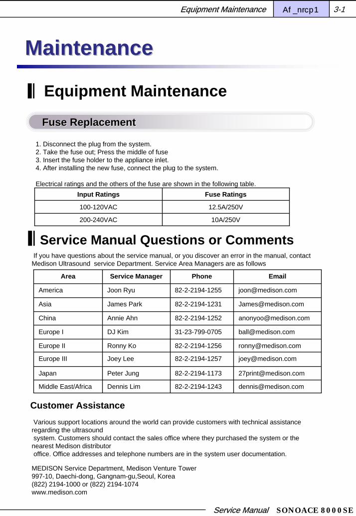
Input Ratings Fuse Ratings
100-120VAC 12.5A/250V
200-240VAC 10A/250V
If you have questions about the service manual, or you discover an error in the manual, contact Medison Ultrasound service Department. Service Area Managers are as follows
Equipment Maintenance
1. Disconnect the plug from the system. 2. Take the fuse out; Press the middle of fuse3. Insert the fuse holder to the appliance inlet.4. After installing the new fuse, connect the plug to the system.
Electrical ratings and the others of the fuse are shown in the following table.
Fuse ReplacementFuse Replacement
Service Manual Questions or Comments
Area Service Manager Phone Email
America Joon Ryu 82-2-2194-1255 [email protected]
China Annie Ahn 82-2-2194-1252 [email protected]
Japan Peter Jung 82-2-2194-1173 [email protected]
Asia James Park 82-2-2194-1231 [email protected]
Europe III Joey Lee 82-2-2194-1257 [email protected]
Europe I DJ Kim 31-23-799-0705 [email protected]
Europe II Ronny Ko 82-2-2194-1256 [email protected]
Middle East/Africa Dennis Lim 82-2-2194-1243 [email protected]
Customer AssistanceVarious support locations around the world can provide customers with technical assistance regarding the ultrasound system. Customers should contact the sales office where they purchased the system or the nearest Medison distributor office. Office addresses and telephone numbers are in the system user documentation.
MEDISON Service Department, Medison Venture Tower 997-10, Daechi-dong, Gangnam-gu,Seoul, Korea(822) 2194-1000 or (822) 2194-1074www.medison.com
MaintenanceMaintenance
Equipment Maintenance Chapter 3 3-1

Service Manual SONOACE 8000SE
The exterior surfaces of most MEDISON ultrasound systems can be disinfected using a recommended disinfectant with a wipe method. You can use the following procedure to disinfect system surfaces on these systems.
Always use protective eyewear and gloves when cleaning and disinfecting any equipment.
Use only recommended disinfectants on system surfaces.
Turn off the system and disconnect the system power cord from the wall outlet.Use a soft cloth lightly dampened in a mild soap or detergent solution to clean exterior surfaces on the system.
The following disinfectants are recommended because of both its biological effectiveness (as qualified through the FDA 510(k) process) and its chemical compatibility with MEDISON ultrasound product materials.
Solutions Country Type Active ingredient FDA510
Cidex USA Liquid Gluteraldehyde K924434
Cidex Plus USA Liquid Gluteraldehyde K923744
Mix the disinfection solution compatible with your system according to label instructions for solution strength.A disinfectant qualified by the FDA 510(k) process is recommended.
Wipe the system surfaces with the disinfection solution, following disinfection label instructions for wipedurations, solution strengths, and disinfectant contact duration. Ensure that the solution strength and durationof contact are appropriate for the intended clinical application.
Air dry or towel dry with a sterile cloth according to the instructions on the disinfectant label.
CleaningCleaning
Caution
Warning
Equipment Maintenance Chapter 3 3-2
SYSTEM SURFACES
DisinfectionDisinfection

Service Manual SONOACE 8000SE
You may lose information files on user setting or patients, because of shock on the product or internal error. Thus, back-up on a regular basis.
Minor software updates may be carried out without any prior notice of the manufacturer.
Should errors occur in the operating system (Linux), and you desire to upgrade the operating system, please follow the specifications of the operating system manufacturer.
User SettingUser Setting
User Setting Back up
ients may not back-up the user setting of the product.
ontact the Medison Customer Service Department to attain support to back-up.
rite down and Save information on user setting to prevent the possible loss of files before
ack-up.
evertheless, clients may back up the user setting on GA Table used in obstetrics diagnosis.
r further information please refer to “Chapter 4. Before Scanning”.
Patient information Back-upClients may back up diagnosis using SonoView software. For further information, please refer to “Chapter 9. Image management” in this manual.
The system automatically saves basic information of patients. Should you wish to reinstall the system due to system error, please ask the Medison Customer Service Department to retrieve the basic information and diagnosis images stored in the system
The software of the product may be updated to enhance performance. Clients may not change the software; attain support from Medison Customer Service Department to update the software.
Caution
Caution
Equipment Maintenance Chapter 3 3-3
Administration of Information
Patient InformationPatient Information
SoftwareSoftware

Service Manual SONOACE 8000SE
Always use protective eyewear and gloves when cleaning and disinfecting probes and biopsy guide adapters.
Probes must be cleaned after each use. Cleaning the probe is an essential step prior to effective disinfection or sterilization. Be sure to follow the manufacturer’s instructions when using disinfectants.
Do not allow sharp objects, such as scalpels or cauterizing knives, to touch probes or cables.
When handling a probe, do not bump the probe on hard surfaces.
Probe is the most important factor in image quality. Optimal imaging cannot be attained without the correct probe. The system is optimized for use based on your probe selection.
Do not use a surgeon’s brush when cleaning probes. The use of even softbrushes can damage the probe.During cleaning, disinfection, and strilization, orient the parts of the probe that must remain dry higher than the wetted parts until all parts are dry. This will help keep liquid from entering non-liquid-tight areas of the probe.
Disconnect the probe from the system.
Remove any sheaths, biopsy guide adapters, or biopsy needle guides(biopsy guide adapters are re-usable portion of the biopsy guide and can be sterilized.)
Discard sheaths(sheaths are single-use item)
Use a soft cloth lightly dampened in a mild soap or compatible cleaning solution to remove any particulate matter or body fluids that remain on the probe or cable.
To remove remaining particulates, rinse with water up to the immersion point.
Wipe with a dry cloth; or wipe with a water-dampened cloth to remove soap residue, and then wipe with a dry cloth.
Caution
Caution
Warning
Equipment Maintenance Chapter 3 3-4
Probe Management

Service Manual SONOACE 8000SE
Sterilize the device only for vaginal and rectal probing. A 10-6 reduction in pathogens should be reached following the sterilization procedures in this manual and using the following MEDISON recommended solutions. The following disinfectants are recommended because of both its biological effectiveness (as qualified through the FDA 510(k) process) and its chemical compatibility with MEDISON ultrasound product materials.
Equipment Maintenance Chapter 3 3-5
Disinfection or Sterilization
Solutions Country Type Active ingredient FDA510
Cidex USA Liquid Gluteraldehyde K924434
Cidex Plus USA Liquid Gluteraldehyde K923744
If a pre-mixed solution is used, be sure to observe the solution expiration date.
The type of tissue it will contact during use dictates the level of disinfection required for a device. Ensure that the solution strength and duration of contact are appropriate for disinfection or sterilization. Be sure to follow the manufacturer’s instructions. In neurosurgical application, sterilized probes should be used with a pyrogen-free sheath.
Warning
Using a non-recommended disinfection solution, incorrect solution strength, or immersing a probe deeper or for a period longer than recommended can damage or discolor the probe and will void the probe warranty.
Do not immerse probes longer than one hour, unless they are sterilizable. Probes may be damaged by longer immersion times. Sterilize probes using only liquid solutions. Using autoclave, gas(EtO), or other non-MEDISON-approved methods will damage your probe and void your warranty.
Caution

Service Manual SONOACE 8000SE
Mix the disinfection solution (or sterilization solution, for sterilizable probe) compatible with your probe according to label instructions for solution strength. A disinfectant qualified by the FDA 510(k) process is recommended.
Immerse the probe into the disinfection solution (or sterilization solution, for sterilizable probe) as shown in the figure below for your probe.
Follow the instructions on the disinfection (or sterilization, for sterilizable probe) label for the duration of probe immersion. Do not immerse probes longer than one hour, unless they are sterilizable.
Using the instructions on the disinfectant or sterilization label, rinse the probe up to the point of immersion, and then air dry or towel dry with a clean cloth. (Or a sterile clothe, for sterilizableprobe).
Examine the probe for damage such as cracks, splitting, fluid leaks, or sharp edges or projections. If damage is evident, discontinue use of the probe and contact Medison Customer Service Department.
[Figure 3-1] Disinfection of Probes
Equipment Maintenance Chapter 3 3-6

Service Manual SONOACE 8000SE
The external surfaces of reusable biopsy guide adapters can be sterilized using one of the following procedures. A 10-6 reduction in pathogens should be reached by following the sterilization procedures in this manual.
Always use protective eyewear and gloves when cleaning and disinfecting probes and biopsy guide adapters.
Biopsy guide must be cleaned after each use. Cleaning the biopsy guide adapter is essential steps prior to effective disinfection or sterilization. Be sure to follow the manufacturer’s instructions when using disinfectants.
Biopsy guide and cables should not contact with sharp things like scalpel.
When handling a biopsy guide, do not bump it on hard surfaces.
Do not use bleach to clean or sterilize the biopsy guide adapter. Using bleach on the adapter may cause damage and will void your warranty.
CleaningAfter use, remove the biopsy guide assembly from the probe.Disassemble the biopsy guide into its component parts, if applicable. Using a small brush and water, scrub each part to remove trapped material from the biopsy guide adapter.Rinse with water to remove remaining particulates.
SterilizationSterilize the biopsy guide adapter by autoclaving (Steam) or using gas (Ethylene Oxide). After sterilization, follow the proper post-sterilization procedure for the sterilization method used.Inspect the biopsy guide adapter for damage such as cracks, rust or breakage. If damage is evident, discontinue use of the biopsy adapter and contact Medison Customer Service Department.
Cleaning and sterilization of stainless steel biopsy guide
Warning
Caution
Equipment Maintenance Chapter 3 3-7
Biopsy Guide Adapter And Needle Guide

Service Manual SONOACE 8000SE
CleaningAfter use, remove the biopsy guide assembly from the probe.Disassemble the biopsy guide into its component parts, if applicable. Discard the single-use parts. These parts cannot be resterilized.Using a small brush and water, scrub each part to remove trapped material from the reusable components.Rinse with water to remove remaining particulates.
Sterilization
Reusable plastic biopsy guide adapters can be sterilized only by using a chemically compatible cold-sterilization solution. Sterilization by autoclaving or by using gas or radiation will permanently damages these parts.
The following disinfectants are recommended because of both its biological effectiveness(as qualified through the FDA 510(k) process) and its chemical compatibility with MEDISON ultrasound product materials.
Sterilize the components by using a chemically compatible cold-sterilization solution. A sterilant qualified by the FDA 510(k) process is recommended. Ensure proper contact time (usually 10 hours) and solution temperature used.
After sterilization, follow the proper post-sterilization procedure for the sterilization method used.
Inspect the components for damage such as cracks, rust or breakage. If damage is evident, discontinue use of the biopsy adapter and contact Medison Customer Service Department.
Cleaning and sterilization of plastic biopsy guide adapter.
Solutions Country Type Active ingredient FDA510
Cidex USA Liquid Gluteraldehyde K924434
Cidex Plus USA Liquid Gluteraldehyde K923744
Caution
Equipment Maintenance Chapter 3 3-8

Service Manual SONOACE 8000SE
Trouble Shooting Trees
[Figure 3-2] Tree of System does not power on
Is the system plugged in ?
Is fuse normal ?
Yes
NoPulgged In !
NoChange Fuse
Yes
Is there AC at the walloutlet ?
No
Yes
Check the power line inhospital
Check the Power Supply
System does not Power On / Boot upSystem does not Power On / Boot up
Equipment Maintenance Chapter 3 3-9

Service Manual SONOACE 8000SE
[Figure 3-3] Tree of noise in Image format
Noise is appear in image format
Is there any electricaldevices that affect the
system ?
Use another room's wall outlet
Check Probes
Yes
No
Keep the system away from thoseelectrical devices
Noise in Image formatNoise in Image format
Equipment Maintenance Chapter 3 3-10

Service Manual SONOACE 8000SE
[Figure 3-4] Tree of track ball check
The trackball is low sensitive !
Does the trackball move at all ? Remove the ball from the trackball unit,
and clean it.
Replace the trackball unit
Yes
No
Track BallTrack Ball
Equipment Maintenance Chapter 3 3-11

Service Manual SONOACE 8000SE
[Figure 3-5] Tree of unable to record to VCR
Unable to record to VCR !
Is the VCR properlyconnected ?
Is the VCR tape put intothe drvice ?
Is recording unable evenby manual operation ?
VCR output of systemO.K ?
No
Yes
Check that all signal. ang power supply cableconnections to the VCR unit are OK.
Put the tape into the device and rewind it.
Check the signal cable connectionsbetween VCR and rear panel
Replace DSC B/D
Yes
Yes
Yes
No
No
No
Replace VCR
Unable to record to VCRUnable to record to VCR
Equipment Maintenance Chapter 3 3-12

Service Manual SONOACE 8000SE
[ Figure 3-6] Tree of unable to use printer
Unable to use Printer
Is the printer properlyconnected ?
Are there print papers left ?
Is proper configuration forthe print key set ?
Check that all signal. power supply cable connections between printer and system are O.K.
Insert the printer papers
Configure the print key
No
Yes
No
Yes
No
Is printing unavailableeven by manualoperation ?
Still no image on the printout
Video output of system O.K ?
Yes
No
Yes
No
Yes
No
Yes
Check the signal cable
Printer O.K
Replace the printer
Replace the PCC B/D
Unable to use Printer
Equipment Maintenance Chapter 3 3-13

Service Manual SONOACE 8000SE
Chapter 4
Installation
Before Installation
Connecting peripherals
System Appearance
Foot S/W Installation
Probe Hanger Installation
4-1
4-3
4-8
4-10
4-13

Service Manual SONOACE 8000SE
The SA8000SE Ultrasound system and its accessories are shipped in two cartons.To unparck the unit
To unpack the 15” VGA monitorRemove or cut the binder tapeCarefully lift the 15”VGA monitor and place it on a flat, secure surfaceTake out the accessory and set it in safe place
To unpack the unitRemove or cut the binder tape.Carefully lift the main console, Probe box from the carton and place it on a flat, secure surface.Take out the accessory and set it in safe placeSave all shipping materials in case the unit requires additional transportation
pon arrival, inventory the shipment with the carrier’s driver.
arefully inspect the packing material for obvious signs of damage such as crushed, punctured,
orn, broken, wet or rattling packages.
f damage is not evident, sign and stamp a bill of lading “condition of contents unknown –subject
o inspection.”
f damage is evident, contact your Purchasing Department for action, have the carrier’s driver
ndicate the damage on the damage on the freight bill, and sign all copies of the bill.
uring formal inspection, you should :
pen all packages within 15 days of receipt for a complete inspection of the consignment.
eport concealed damage to the carrier within 15 days of receipt or the carrier may not accept
iability.
Installation Chapter 4 4-1
InstallationInstallation
Befor installation
PrePre--installationinstallation
UNPACKING INSTRUCTIONSUNPACKING INSTRUCTIONS
MEDISON or local distributor will make available on request circuit diagrams, components partlist, descriptions, calibration instructions or other information which assist your appropriately qualified technical personnel to repair those parts of equipment which are designed by Medison as repairable
Caution

Service Manual SONOACE 8000SE
The product is heavy, but fragile to shock, thus be cautious when you are moving the product, especially walking down the stairs carrying it.
When you are moving the product, note the following.
Do not lift up the product to move it. You should have at least 4 adults to move the product carefully to avoid any injury.
Make sure that peripheral devices such as monitor are securely fastened to the system. Put away accessories such as the probe before moving the product.
The wheels are designed to move back/forth; to move the product left/right, please make short, multiple back/forth movements gently pushing it to the direction you wish to turn.Move the product slowing after having checked if the wheel locks are loose
Moving the productMoving the product
Product InstallationProduct Installation
Installation Chapter 4 4-2
Avoid humidity.
Avoid direct sunlight.
Avoid severe temperature change. The optimal conditions for the product are temperature of 10° ~ 35° Celsius and humidity of 30% ~ 75%.
Avoid placing the product near heat sources.
Avoid places with poor ventilation.
Avoid vibration.
Avoid chemical substance.
Placing the product near a generator, Roentgen devices or broadcast cables may result in noise and abnormal visual images. Using the power source with other electric devices may also induce noise.
Caution
Keep the following in mind when using the product.
Do not insert anything, especially metal piece, into the product.
Do not attempt repairs yourself: disassembling voids the warranty.
Do not block the ventilation slot.
Plug in the AC cord after the whole components are connected properly: otherwise, damage to the product may occur.
When unplugging the power cord, make sure to grip the plug, not the cord.

Service Manual SONOACE 8000SE
This System provides a lamp for the Alpha Numeric Keyboard at a dark place. The connector is located under the control panel, and you can turn it on or off by using the switch on its hat.
[Figure 4-1] Connecting Peripherals
Connecting Peripherals
Lamp ConnectorLamp Connector
Installation Chapter 4 4-3
[Figure 4-2] Lamp switch On/Off

Service Manual SONOACE 8000SE
It is possible to connect with peripheral devices such as VCR, Color video printer, and so on through Front Panel, which is inside of system rack.
Do not assemble or disassemble it while it is turned on. It may cause malfunction of the system. Also, if you drop the illuminator or shove it by force, it may be broken down.
If raindrops or water drops spatter on the illuminator, or a high percentage of humidity is shown, please do not operate it. Because you many be in danger of an electric shock.
Caution
Caution
Front PanelFront Panel
Installation Chapter 4 4-4
[Figure 4-3] Front Panel
AUDIO(Input/Output)It is possible to input and output Audio signal. .
You cannot use Audio Input in the Front Panel at the same time, but you can use Output at the same timeCaution
VHS(Input/Output)Connect with VCR through VHS system.
You cannot use VHS Input in the Front Panel at the same time, but you can use Output at the same time.Caution
S-VHS(Input/Output)
Connect with VCR through S-VHS system.
You cannot use S-VHS Input in the Front Panel at the same time, but you can use Output at the same time.Caution
Service Manual SONOACE 8000SE
A connector, which connects with foot switch, is on the front and lower part of system.
PRINTER (Output)Connect with Echo printer.
PRINT REMOTE (Output)It is used to print remotely by connection with Echo printer.
It is possible to connect with Storage devices, Inkjet Printer and so on through USB connector, which is on left side of system rack.
Foot Switch ConnectorFoot Switch Connector
USB ConnectorUSB Connector
Installation Chapter 4 4-5
Please set/set off USB device after turn off the system power completely.
If you set/set off USB device during working, It may cause wrong working
In case of USB MO Driver, do not use other devices with it.
Caution
Storage devicesSA8000SE supports many kinds of storage devices like USB MO Driver, USB CD-RW Driver and Flash Memory Media to backup & restore data of SonoView or Measure packages.
SonoView support: USB MO Driver, USB CD-RW Driver and Flash Memory Media
Measure package support: USB MO Driver, Flash Memory media
Inkjet printersYou can use a Postscript interchange printer for SA8000SE. The connector should be connected to the USB port of Rear Panel.
Available printers are HP DeskJet880C, HP DeskJet895C, HP LaserJet1200, HP DeskJet6122 and HP DeskJet5550.
Please entrust the Medison Customer Service Department with the installation of the printer and driver.Caution

Service Manual SONOACE 8000SE
It is possible to connect with peripheral devices such as monitor, printer, VCR, and so on through Real Panel, which is at backside of system.
Foot Switch ConnectorFoot Switch Connector
Installation Chapter 4 4-6
[Figure 4-4] Rear Panel
VGA1 / VGA2 (Output)Print out VGA signal with monitor.
PARALLEL (Output)Connect general PC printer through parallel port
RS-232C (Input/Output)Input or output port for RS-232C
You cannot use RS-232C in the Front Panel at the same time.Caution

Service Manual SONOACE 8000SE
CAUTION
LAN (Input/Output)It enables you to use DICOM. It transfers the patient’s information to other servers through DICOM Network.
AUDIO (Input/Output)It is possible to input and output Audio signal.
Installation Chapter 4 4-7
You cannot use Audio Input in the Front Panel at the same time, but you can use Output at the same time.
VHS (Input/Output)Connect with VCR through VHS system.
You cannot use VHS Input in the Front Panel at the same time, but you can use Output at the same time.
Caution
Caution
S-VHS (Input/Output)Connect with VCR through S-VHS system..
You cannot use S-VHS Input in the Front Panel at the same time, but you can use Output at the same time.Caution
PRINTER (Output)Connect with Echo printer.
PRINT REMOTE (Output)It is used to print remotely by connection with Echo printer.
MIC (Input)Connect with microphone.
ECG ConnectorConnect with ECG Module.
[Figure 4-5] Lead II ECG

Service Manual SONOACE 8000SE
Probe holderProbe holder
Installation Chapter 4 4-8
This system provides a probe holder at the left side of the control panel. You can put a probe into it.

Service Manual SONOACE 8000SE
Chapter 5
Initial and Monitor Tests 5-3
Initial Setup 5-2
Functional Tests 5-4
Wiring and Cautions 5-1
Performance Tests

Service Manual SONOACE 8000SE
Performance Tests Chapter 5 5-1
Performance TestsPerformance Tests
Wiring and Cautions
WarningsWarnings
Never open the safety cover of this equipment. Internal parts of the equipment are supplied with high voltage electricity. All internal repairs and part replacements must be carried out only by the Medison Customer Service Department.
Electrostatic Discharge (ESD), generally known to be caused by shocks of static charges, can occur in natural conditions. ESD occurs most commonly in dry conditions, such as during operation of heaters or air conditioners. ESD also occurs when contacting metal door handles, file cabinets, computer parts or even another person. Static charges and ESD are produced when electrically charged materials release electricity to charge less charged materials. It is possible that the static charges released by the system user or the patient may damage the ultrasonographic system or the probe.
Always observe the following guidelines to prevent damages by ESD:
1. Spray anti-static charge spray over the carpet or the linoleum.
2. Use anti-static charge mats.
3. Ground the system and the patient’s table or bed.

Service Manual SONOACE 8000SE
Performance Tests Chapter 5 5-2
Initial SetupInitial setup includes both the hardware setup and the software setup. The system coordination is done in accordance with the COA (Customer Order Acknowledgement). This test must be conducted after a proper inspection of the equipment installation as described in Chapter 4.
-Do not inspect the equipment functionality with items not recommend by Medison Co., Ltd.

Service Manual SONOACE 8000SE
Performance Tests Chapter 5 5-3
Initialization and Monitor Tests1. If the equipment is not powered on yet, use a hospital power cord of 15 amps or higher.
2. Insert printer paper and a video tape appropriate for the product specification.
3. Properly connect the probe to the two probe connectors.
4. Power on the system. Upon power-up, the internal program begins the initialization process.
5. After the system initialization process and the self-test are complete (about 3 to 5 minutes),the 2D mode screen will be displayed.
6. Using the System Setup items, you can verify the versions of the software applied to thecurrent equipment on the monitor screen.
7. Select a probe to apply another 2D image.
8. Check the following on the monitor (if the monitor has a color problem, see “Setting Up” in Chapter 7).
- Adjust brightness and contrast of the monitor from minimum through maximum and checkfor any distortions.
- Verify that the image is displayed in the center of the screen. Verify the horizontal and vertical resolutions.
- Check for any problems around each corner.
Service Manual SONOACE 8000SE
Performance Tests Chapter 5 5-4
Functional TestsFollow the procedure above to test the system functions. If there is any problem with the system, conduct the test again.
If the test is successful, check the following:
- Is the image displayed exactly in the center of the monitor screen?
- Are all the lights on the control panel working?
- Are all the toggle switches, slides, and the trackball working?
If there is any problem, follow the “Initial Setup” procedure again.
Service Manual SONOACE 8000SE
Performance Tests Chapter 5 5-5
General System Confidence Test General System Confidence Test
Run Diagnostics on the system to view information for the main check points and the main tests within the PCB.
User Interface Tests User Interface Tests
Run User Interface Tests to check the functionality of the User Interface for the Operating System. Control Panel functions can also be implemented on the screen. While this test is in progress, other tests can also be run. For information on the keys and their functions, see Seby Operation Manual.
2D Image Test2D Image Test
1. Power off the system. The system will shut down in 10 to 20 seconds. Then power on the system again.
2. Select Curved Array Probe.
3. Apply 2D Phantom Image.
4. Apply the POWER function at 100%.
5. Adjust the TGC gain to produce the 2D image with the least noise. Reduce gain while maintaining the image on the far side.
6. Adjust the horizontal and vertical placement so that the phantom image is in the appropriate location.
7. Once the phantom is placed in the appropriate location, adjust the axial and lateral functions so that the image does not disappear and noise is not produced.
8. After the phantom image adjustment is complete, adjust the focus of all holes within each phantom structure.
9. Use the menu keys to conveniently implement various images.
10. In PW Mode, the menu items can be used to obtain optimal images as well.
2DDirection, Application, M line, Density, Focus +, -, 2D, THI, DEPTH, FOCAL POS TSI OPT, ZOOM, POWER, TGC, DUAL
COLORDirection, M line, Density, Maps, COLOR, THI, DEPTH, FOCAL POS, ZOOM POWER, TGC, DUAL
M-modeDirection, Application, Density Format, M, THI, DEPTH, FOCAL POS ZOOM, POWER, TGC
PW DopplerPWD,ANGLE, Simultaneous, SV Size +-, VOLUME, FILTER, SWEEP BASELINE, SCALE, INVERT
PW Doppler + Color or CPA COLOR or CPA

Service Manual SONOACE 8000SE
Performance Tests Chapter 5 5-6
Freehand 3D TestFreehand 3D Test
1. Power off the system. The system will shut down in 10 to 20 seconds. Then power on thesystem again.
2. Select Curved Array Probe.
3. Click the “3D” button to obtain a 3D image.
4. Adjust X, Y, Z, RECT.L, MAG, and TH.L to obtain the desired image.
5. When the image is obtained, press the Freeze button to view the 3D image on the monitorscreen.
6. Press the 2D button to return to the normal mode.
CW Static Probe TestCW Static Probe Test
This test can be run only when the Doppler Phantom is in use.
1. Power off the system. The system will shut down in 10 to 20 seconds. Then power on the system again.
2. Connect the CW probe, and select it. Use Default for Application.
3. Adjust the Doppler gain to obtain the desired Doppler image.
4. After using the Doppler images, click the 2D button to return to the previous screen.
ECG TestECG Test
This test can be run only when the ECG Module is available.
1. Install the ECG Module on the system.
2. Adjust the settings to 1mV amplitude and 60BPM rate.
3. Select the Phased Array Probe, and set Application to Default.
4. Turn on ECG. The ECG Trace will be displayed at the bottom on the monitor.
5. Adjust the ECG Gain to obtain an optimized ECG Trace.

Service Manual SONOACE 8000SE
Performance Tests Chapter 5 5-7
Image Save TestImage Save Test
1. Power off the system. The system will shut down in 10 to 20 seconds. Then power on thesystem again.
2. Select any probe.
3. Click the STORE button to save the image.
4. Click the END EXAM button.
5. Click the REVIEW menu within SONOVIEW to view the saved image.
B & W Printer TestsB & W Printer Tests
This test can be run only when a B/W Printer is installed.
1. If a printer is installed, ensure that it is loaded with paper. If not, load the appropriate paper.
2. Use the Freeze button to obtain a 2D image.
3. Click the Printer button to print out the image on the screen. If the quality of the printedimage is not satisfactory, adjust the brightness and contrast of the printer.
VCR TestsVCR Tests
This test can be run only when a VCR is installed.
1. If a VCR is installed, ensure that it is loaded with a tape. If not, insert a blank tape.
2. Switch between 2D Mode and PW Mode for recording to a VCR.
3. Rewind the recorded tape.
4. After rewinding, click the Utility -> VCR -> Play menu. Then press the Play button on theVCR to play the recorded video. If there is noise on the screen or in the sound, replace theVCR and run the test again.
5. Click the Utility -> VCR -> STOP menu to return to the previous screen.
* The VCR input must be set to external input.

Service Manual SONOACE 8000SE
Performance Tests Chapter 5 5-8
Color Printer TestsColor Printer Tests
This test can be run only when a color printer is installed.
1. If a printer is installed, ensure that it is loaded with paper. If not, load the appropriate paper.
2. Use a phantom to obtain a good 2D image.
3. Select C-Mode, and adjust the color gain to obtain a good C-Mode image.
4. When the image is obtained, press the CAPTURE and PRINT buttons to print out the image.
5. If the quality of the color printout is not satisfactory, adjust the color and brightness menuitems on the printer (bri, con, tint, color, etc.) and run the test again.
End of TestingEnd of Testing
When all the tests are successful, you may proceed to use the equipment. If a problem was discovered during the tests, restart the system and run the tests again.
If the problem persists, please contact MEDISON Customer Support.

Service Manual SONOACE 8000SE
Performance Tests Chapter 5 5-9
Performance Test ChecklistPerformance Test Checklist
Test Item Result Remark
Initialization and Monitor Tests
General System Confidence Test
User Interface Tests
2D Image Test
Freehand 3D Test
CW Static Probe Test
ECG Test
Image Save Test
Peripheral Tests
Service Manual SONOACE 8000SE
Chapter 6
System Organization
System Architecture 6-1
Power Unit 6-3
Probe Select Assembly Board (PSA) 6-6
Beamformer Board (BF) 6-8
Digital Scan Converter Board (DSC) 6-11
PC Carrier Board (PCC) 6-14
Key Matrix PCB 6-17

Service Manual SONOACE 8000SE
System Organization Chapter 6 6-1
System OrganizationSystem Organization
System Organization
Overview Overview
The SA8000SE system consists of six main parts.
- Frame structure and boards that constitute the basic framework
- Power Unit
- Control Unit
- Ultrasound emitter and echo signal receiver
- Image signal processor and analyzer
- Image sound implementation part
The output power map for the POWER UNIT is described in the section “Power Unit” later in this manual.
Control, signal process, signal analysis and all other functions are processed by the internal Pentium processor, and the processed images e transferred using accessories (MOD, CD-RW, FDD, etc.).
For best performance, the system includes an industrial PC with a 64-bit CPU and a main memory of 128 MB.
Also, for system stability, the SA8000SE uses Linux OS.
The SA8000SE system consists of a Continuous Wave Doppler (CW) PCB, a Digital Beamformer (BF) PCB, a Digital Scan Converter (DSC) PCB, and a Power Supply Unit.

Service Manual SONOACE 8000SE
System Organization Chapter 6 6-2
SA8000SE Functional Block DiagramSA8000SE Functional Block Diagram
Beamformer #1
- BF Control Logic- Transmit Pulse Generation (16 units)- Limiter (32 units)- TGC Amp (16 Dual TGC amplifier)- A/D Conversion (16, 8bit)- Synthetic Aperture Support- Dual line Receiving Support
Digital Scan Converter (DSC)
- Quadrature Demodulation- Generate I, Q signals for Spectral Doppler and Color Doppler- Log compression and envelope detection- Gain and Dynamic Range Setting- Generate Gray Scale data- Wall Filtering and FFT for Spectral Doppler- Generate Spectral Data- Generate Doppler Audio signal- Wall Filtering and Mean Velocity Estimation for Color Doppler- Post Processing for Color Doppler- Generate Color Doppler data- Generate TGC data for Beamformer Board
------------------------------------------------- Generate all major control signals- Perform Real Time Control and generate signal- A/D conversion for ECG- Cine memory- Perform Azimuth & Axial interpolation- Write San Line data in Frame memory- Read data from Frame memory synchronized with monitor H - Sync- Read Zoom & Edge Enhancement- Free Hand 3D Data Path
------------------------------------------------- Image Grabber- Interlace & Non - Interlace video signal output- Video color keying
PCC PCB
- PC Module- CPU : NS Geode GX1 - 300Mhz - Memory : 128 MB- HDD : 80Gbytes (Seagate)
- PC Part (LAN, USB, MIC)- CV & Y/C Decoding for change RGC into a signals- RGC Encoding for change CV & Y/C into a signals- Doppler Audio Processing - System PCI BUS- Video DAC & amplifier
Rear Panel I/O PCBs
1. Rear Panel Left2. Rear Panel Middle3. Rear Panel Right
HDD(80GB)
Primary Master
Control Panel- Mode toggle switch- Track Ball- TGC Volume
Alphanumeric KeyboardSystem Monitor
& Peripherals
Speaker(L)
Speaker(R)
Probe Select Assembly (PSA)
- 3Probe Connector - Probe Detection- Probe ID- Switching Relay (128 units)
CW PCB
- Generate Main Clock 61.6MHz- Transmit Power Control
ECG Module
- ECG Isolation Amplifier- ECG Gain Control
[ Figure 6-1] SA8000SE Functional Block Diagram

Service Manual SONOACE 8000SE
System Organization Chapter 6 6-3
POWER UNIT
Power Output Voltage Power Output Voltage
The SA8000SE Power Supply is designed to work with 115VAC or 230VAC. Always ensure that the power toggle switch on the product is set correctly for the wall power outlet.
The INPUT Voltage Selector is used for setting the power and voltage of the product.
The OUTPUT Voltage Selector is used for setting the power supplied directly from the product to the monitor a printer.
Please refer to the figure below for more information.
1 2 3 4 5 6 7
[ Figure 6-2] Power Supply Output
Part Name Description Remarks
1 Power Code Power supply cable
2 Fuse Holder Holds 2 fuses
3 Input Voltage SelectorMain power setting switch (100V/220V)
5 Output Voltage SelectorSub-power setting switch (100V/220V)
4 Main Power Switch Main power switch
6 Output VoltageSub-power directly supplied by the product for monitor and printer
7 Power Cooling Fan Power cooling fan

Service Manual SONOACE 8000SE
System Organization Chapter 6 6-4
Power Supply Output Voltages Power Supply Output Voltages
Voltage Used by
1 +3.3 VDC Computer, Digital Logic, Beamformer
2 +5VDC Computer,HDD,Digital Logic.Beamformer, K/B
3 -5VDC Computer, Beamformer
4 +12.2VDC Computer,HDD,Digital Logic,Beamformer, Fan
5 -12.2VDC Computer,HDD,Digital Logic,Beamformer, PSA
6 +10 ~ 80 VDC (+HV) Beamformer
7 -10 ~ 80 VDC (-HV) Beamformer
8 0 ~ 5 VDC Acoustic power control
Power Supply Output Voltages Power Supply Output Voltages
AC90V~264V
OUTPUT 2
OUTPUT 1
DDM (+50V)
OUTLET 1 (MONITOR)
OUTLET 2 (PRINTER)
INRUSHCURRENT
LimiterCIRCUITINPUT
FILTER
CIRCUIT
AC IN
AC IN
Input SWITCHMAIN
TRANS
(AC/AC)
AC 110/220VManual Control
S/W
F.G
ADM
RectificationCIRCUIT
OUTLET ON/OFFCIRCUIT
AC 110V/220VManual Control S/W
(+50V)
(GND)
POWER SECTIONOUTPUT 3
DC/DC POWER 1
DC/DC POWER 2
DC/DC POWER 3
+5.2VA±97V
±HV
+5.2VA, VD-5.2VD
+3.5VD
+3.5VA
DC/DC POWER 4
DC/DC POWER 5
DC/DC POWER 6
+12.2VA, VD,VMOT
-12.2VA,VD
DDM IN
DDM IN
INPUT
FILTER
CIRCUIT
P/B, P/O, P·S/W, P/G/S
±HV REMOTE, OTP CIRCUIT
Auxiliary Power
(+5V, +15V)
DDM
FAN(ADM.DDM)
[ Figure 6-3 Power Supply Distribution Diagram
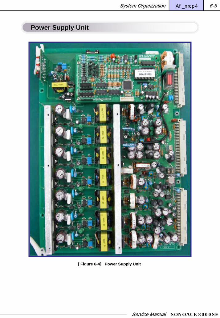
Service Manual SONOACE 8000SE
System Organization Chapter 6 6-5
Power Supply UnitPower Supply Unit
[ Figure 6-4] Power Supply Unit
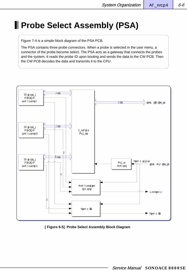
Service Manual SONOACE 8000SE
System Organization Chapter 6 6-6
Probe Select Assembly (PSA)Figure 7-4 is a simple block diagram of the PSA PCB.
The PSA contains three probe connectors. When a probe is selected in the user menu, a connector of the probe become select. The PSA acts as a gateway that connects the probes and the system. It reads the probe ID upon booting and sends the data to the CW PCB. Then the CW PCB decodes the data and transmits it to the CPU.
UniversalHDI S/H
connector 1
UniversalHDI S/H
connector 2
UniversalHDI S/H
connector 3
LatchingRelays
128
128
128
ConnectivitySensor
4
Probe ID
4
4
4
Relay Control
128
from CW BoardProbe select
Probe ID
No Probe
from BF Board
[ Figure 6-5] Probe Select Assembly Block Diagram

Service Manual SONOACE 8000SE
System Organization Chapter 6 6-7
Probe Select Assembly (PSA)Probe Select Assembly (PSA)
[ Figure 6-6] PSA Unit

Service Manual SONOACE 8000SE
System Organization Chapter 6 6-8
Beamformer Figure 6-7 is a functional block diagram of the Beamformer PCB.
The Beamformer consists of 1 PCB. It generates transmission pulses in order to operate the probe elements. The received echo signals are sent through the filter for eliminating noise. Then the signals are amplified to specific levels by the PREAMP and are converted to digital signals for digital beamforming.
The delay them of time digital signals are controlled by the FIFO and then are summed together by the BFIC. This process is called beamforming.
In addition, the Beamformer also performs Dynamic Apodization, Multi Beam Receiving, TGC and other functions for improving the image quality.
Board Specification Board Specification
32ch TX Pulsers (MHIC0201: 16 units)
32ch Limiter
32ch TGC Amp (Dual channel TGC Amp, AD8332: 16 units)
32ch A/D Converter (Dual Channel A/D Converter, AD9288-40: 16 units)
Bipolar TX Pulses
Synthetic Aperture Support
Dual Line Receiving Support
RX Dynamic Aperture Function (16 step max.)
RX Apodization Function (supports curves for different modes)
Trapezoidal Imaging Support
TX Focal Point Support (4 max.)
Board version included in Board

Service Manual SONOACE 8000SE
System Organization Chapter 6 6-9
Beamformer Functional Block Diagram Beamformer Functional Block Diagram
BF IC(32CH)
MCB014B
Pulser(32CH)
MHIC0201
PulseSignalBuffers
HV Switch4 : 1 Mux
Limiter(32CH)
TGC&
PreAmp(32CH)
LFP&
ADC(32CH)
TGC curve /reference generator & Buffer
TX_out
TGC를 위한
TGC curve 발생
Digital Beamforming
To DSC
Amplifies the 5V signals to 80V, which is sufficient for operating the probes.
Amplifies the 3.3V signals to 5V so that the Pulser IC can recognize the signals properly.
Since the BFIC operates at 3.3V, the TX_out signals do not exceed 3.3V.
Uses 4:1 Mux in order to operate all of the 128 elements with the 32 pulsers.
TGC after amplifying the echo signals to 50dB.
A/D conversion.
Generates TGC curve for TGC.
HV (80V) elements are removed from the received signals.
[ Figure 6-7] Beamformer Functional Block Diagram

Service Manual SONOACE 8000SE
System Organization Chapter 6 6-10
Beamformer PCBBeamformer PCB
[ Figure 6-8] Beamformer PCB

Service Manual SONOACE 8000SE
System Organization Chapter 6 6-11
Digital Scan Converter (DSC)The Digital Scan Converter PCB consists of three main parts: a Digital Signal Processing (DSP) Part, a Digital Scan Converter (DSC) Part, and a Video Manager (VM) Part.
DSP PartDSP Part
The DSP Part consists of a 2D mode part, a Spectral Doppler Part, and a Color Doppler Part.
The 2D mode part receives the beamformed output signals, generates B/W signal (2D image) data and sends it to the DSC Part.
The Spectral doppler mode part separates the RF signals received for Doppler direction separation into I (Inphase) signals and Q (Quadrature) signals. Then it uses the clutter filter to remove the clutter noise in which is a kind o wall noise from vein wall out of the signals. The signals with wall noise removed are sent to the PCC Board for the Doppler Sound process, and they are sent to the FFT circuit, where the basic Doppler elements Power, Velocity, and Variance are analyzed.
The Color Doppler mode part receives the I signals and Q signals, removes the wall noise and adds colors by using Color Flow Mapping.
DSC PartDSC Part
The DSC Part consists of the image filter circuit (which improves the image quality), the frame memory part (which writes the scan line data and displays the monitor on the H-sync), Zoom, and FreeHand 3D Path.
The DSC Part combines into one screen the information from the 2D / Spectral Doppler / Color Doppler modes which are generated through different paths.
VM PartVM Part
The VM Part converts the digital data into RGC signals for displaying on the monitor and converts the digital signals into analog signals. It also combines the menu information from the PC and the image information from the system together for displaying on the screen.
It generates various video output signals in order to support other external devices.

Service Manual SONOACE 8000SE
System Organization Chapter 6 6-12
Digital Scan Converter(DSC) Digital Scan Converter(DSC) Functional Block DiagramFunctional Block Diagram
DSP FPGA
DSCFPGA
VMFPGA
MGA015
MidProcessor
MGA016
Color Doppler
Processor
CPLDPDSP
DSP1
DSP2
DRAM
SDRAM
SDRAM
SDRAM
SDRAM
SDRAM
SSRAM
ADSP
SSRAM
SSRAM
ADC
I TO NISDRAM
Post ControlSDRAM
Fiel
d M
emor
y (G
)
NI TO ISDRAM
OSC
Fiel
d M
emor
y (B
)
Fiel
d M
emor
y (R
)
PC Host Controladdress mapping
Produces 2D ImageProduces I and Q signalsRemoves Clutter
Color Mapping
Removes Multi Beam artifact
Debugging 전용RAM
기본 도플러data 처리
Real Time autotrace 기능 담당
Color data scan conversion
BW data scan conversion
BW data scan conversion
Frame Memory
SA8000의Iput,FM,Loop3개의 CTR를1개로 통합
1.2V로동작
3D, Loop Memory
CINE Memory
CINE Memory
DSC ControlVM ControlRTC Control
ECG신호를 디지털 신호로 변환
Pixel IntpAzimuth Intp
F.AF.I
Read ZoomE/E
Converts Image V-sync, H-Sync toVGA V-Sync, H-Sync
Post MapGray BarColor KeyingRGB conversion
Header Mapping
Image V-syncH-Sync
Generates
ToPCC PCB
FromBF PCB
RAM for debugging
Operates at 1.2V
Produces color box (combines the existing 4 into 1)
Basic Doppler data process
Performs real-time auto trace
Combines SA8000 input, FM, loop into 1 CTR.
Converts ECG signals into digital signals
[ Figure 6-9] DSC PCB Block Diagram

Service Manual SONOACE 8000SE
System Organization Chapter 6 6-13
Digital Scan Converter (DSC) PCBDigital Scan Converter (DSC) PCB
[ Figure 6-10] DSC PCB

Service Manual SONOACE 8000SE
System Organization Chapter 6 6-14
PC Carrier (PCC) PCBThe PC Carrier (PCC) PCB consists of three main parts: a PC Part, a VM Part, and a Doppler Sound Part.
PC Part Components and FunctionsPC Part Components and Functions
The PC Part consists of the PC Module, which is the central part of the system, and the PC Interface which controls the data and signals of the PC and the System. The PC Part controls the entire PCC PCB and manages the data input and output.
Video Manager Part Components and FunctionsVideo Manager Part Components and Functions
The Video Manager Part is the last device that the signals go through before being sent as display signals.
The Video Manager Part consists of the DAC (which converts digital signals into analog signals), the Encoder (which converts digital signals into VCR signals), and the Decoder (which allows the external video signals to be displayed on the system).
Audio Sound Part Components and FunctionsAudio Sound Part Components and Functions
The Audio Sound Part is the last device that processes Doppler Sound for the Spectral Doppler.
The Audio Sound Part consists of the D/A converter (which converts digital signals into analog signals), a filter (LPF) (which removes the noise from Doppler signals), and the Power Amp (which amplifies the audio to sufficient output levels).
This part also includes a microphone that can be used for adding audio information when recording the ultrasonographic scanner video.
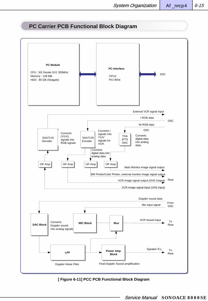
Service Manual SONOACE 8000SE
System Organization Chapter 6 6-15
PC Carrier PCB Functional Block Diagram PC Carrier PCB Functional Block Diagram
PC Module
CPU : NS Geode GX1 300MHzMemory : 128 MBHDD : 80 GB (Seagate)
PC Interface
CPLDPCI 9054
SAA7115Decoder
SAA7129Encoder
TDA8775DAC
OP Amp OP AmpOP AmpOP Amp
MIC BlockDAC Block
LPF Power Amp Block
Mux
Doppler sound data
Mic input signal
VCR Sound Input
Speaker R.L
Doppler Noise Filter
ConvertsDoppler soundInto analog signals
Final Doppler Sound amplification
External VCR signal Input
VCR image signal input (VHS Input)
(Y/UV) 신호를RGB 포멧으로
변환
I RGB data
I 신호를VCR용의
Y/UV신호로변환
NI RGB data
VCR image signal output (VHS Output)
BW Printer/Color Printer, external monitor image signal output
Main Monitor image signal output
Digital data의Aalog 변환
DSC
Rear
FromDSC
ToRear
ToRear
DSC
DSCConverts (Y/UV) signals into RGB signals
Converts digital data into analog data.
Converts digital data into analog data.
Converts I signals into Y/UV signals for VCR.
[ Figure 6-11] PCC PCB Functional Block Diagram

Service Manual SONOACE 8000SE
System Organization Chapter 6 6-16
PC Carrier PCBPC Carrier PCB
[ Figure 6-12] PC Carrier PCB

Service Manual SONOACE 8000SE
System Organization Chapter 6 6-17
Key Matrix PCB
Key Matrix Components and FunctionsKey Matrix Components and Functions
SEBY’s K/M constitutes the Key Matrix that supports the UI (User Interface). When the user clicks a function button, the associated command is sent to the system, so that the system can perform the associated operation. It acts as a bridge between the user and the system.
SEBY’s UI consists of a Key Matrix B/D (BD-340-KM) and a Alpha/Numeric Key Interface B/D (BD-336-KI). The TGC VR Module (BD-336-TGC) is included in a separate Sub B/D.
[ Figure 6-13] Key Matrix PCB

Service Manual SONOACE 8000SE
System Organization Chapter 6 6-18
Key Matrix Functional Block DiagramKey Matrix Functional Block Diagram
Key
control
CPLD
XC 95144
TQ144
+3.3V
uP89c51
DA
TA
[ 0..7
]
SD
[0..7
]
SA
[0..
7 ]
SR[8..15]
SC[0..7]
+5VA
ADC0808
SD[0..7]
MAX239
Power Control Signal
POWER
Key
Power Control
Connector
Foot s/w
Alpha Numeric Key
BD- 336-TGC
Key Matrix
+5V , +12V
TTXA,B
TTYA,B
TBR,TBL
TrackBall HT82M39A
PS2 Mouse
PS2PORT
ALPHA/ NUMERICPORT
[ Figure 6-14] Key Matrix Block Diagram

Service Manual SONOACE 8000SE
Chapter 7
Setting up
Main Monitor Setting 7-1
Administration Mode 7-2
Network Setting 7-3
C-MOS Setting 7-4
System Upgrade 7-7

Service Manual SONOACE 8000SE
Setting Up Chapter 7 7-1
Setting UpSetting Up
Main Monitor Setting
Brightness and Contrast Setting Brightness and Contrast Setting 1. Press the “MENU” button on the front of the monitor.
2. Press the “+” and “–” buttons to set Brightness to 73% and Contrast to 65%.
3. Press the “MENU” button again to finish the screen adjustment.
Figure 7-1 Contrast Adjustment
Figure 7-2 Brightness Adjustment
CONTRAST
- + 50
BRIGHTNESS
- + 50
Other MENU SettingsOther MENU Settings1. Hold down the “MENU” button on the front of the monitor for about 10 seconds until
“Main Menu” is displayed.
2. Press the “+” and “–” buttons to select an item to adjust and check or change the setting value.
3. Set Overall Image size to 270mm x 202mm.
4. Set Red, Green, and Blue levels to 83%.
EXIT
COLOR
SIZE / CENTER
GEOMETRY
UTILITY
MAIN MENU
ENTER : MENU SELECT : + / -
FH : 37.8 KHz FV : 60.3 Hz
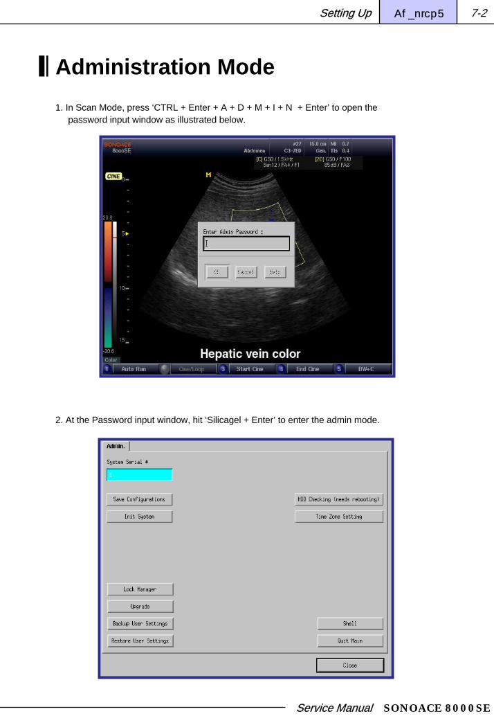
Service Manual SONOACE 8000SE
Setting Up Chapter 7 7-2
Administration Mode1. In Scan Mode, press ‘CTRL + Enter + A + D + M + I + N + Enter’ to open the
password input window as illustrated below.
2. At the Password input window, hit ‘Silicagel + Enter’ to enter the admin mode.

Service Manual SONOACE 8000SE
Setting Up Chapter 7 7-3
Network Setting1. Press the Setup button. When the Setting window is displayed, click the Peripherals Tab.
2. Fill out information ueeded for the Host Setting group items and click Apply.
3. To use DHCP, select Using Dynamic IP Configuration, enter Hostname and click Apply.

Service Manual SONOACE 8000SE
Setting Up Chapter 7 7-4
C-MOS Setting
ROM PCI/ISA BIOS ROM PCI/ISA BIOS
BIOS FEATURES SETUP BIOS FEATURES SETUP

Service Manual SONOACE 8000SE
Setting Up Chapter 7 7-5
CHIPSET FEATURE SETUP CHIPSET FEATURE SETUP
POWER MANAGEMENT SETUPPOWER MANAGEMENT SETUP

Service Manual SONOACE 8000SE
Setting Up Chapter 7 7-6
PNP/PCI CONFIGRATION PNP/PCI CONFIGRATION
INTERGRATED PERIPHERALSINTERGRATED PERIPHERALS

Service Manual SONOACE 8000SE
Setting Up Chapter 7 7-7
System Upgrade1. Insert a storage device into the MO or Fresh Memory USB Port.
2. Click the Upgrade button in the Admin window.
3. Select the device which was the Upgrade file

Service Manual SONOACE 8000SE
Setting Up Chapter 7 7-8
4. Select the Upgrade Version.
5. The system will ask whether the file is correct. Hit “y”.

Service Manual SONOACE 8000SE
Setting Up Chapter 7 7-9
6. When the upgrade is complete, the system will ask whether to update the image user setting to factory setting.
7. Reboot the system to apply the upgrade.

Service Manual SONOACE 8000SE
Chapter 8
Disassembly
Overview 8-1
Disassembly 8-2

Service Manual SONOACE 8000SE
Disassembly Chapter 8 8-1
DisassemblyDisassembly
Overview
OverviewOverviewThis chapter contains instructions for disassembling and assembling the SA8000SE system.
The system must be disassembled only by the Medison after-sales personnel.
Please read the safety instructions in Chapter 2 before proceeding.
High voltage power exists within the system. The system must be disassembled only by the Medison after-sales personnel. If working on the system with power on, do not use the anti-static wrist band while being grounded to the system chassis.
Warning

Service Manual SONOACE 8000SE
Disassembly Chapter 8 8-2
Disassembly
SA8000SE Front and BackSA8000SE Front and Back
[ Figure 8-2] SA8000SE Back [ Figure 8-1] SA8000SE Front

Service Manual SONOACE 8000SE
Disassembly Chapter 8 8-3
Opening Front CoverOpening Front Cover
Press the 2 hook locks with thumbs and pull the cover out.
Unscrew the 2 screws and disconnect the connector.
Push the Front Panel in the direction of the arrow to release the lock and then pull it out.
Unscrew the 5 screws.
Pull out the PSA PCB.

Service Manual SONOACE 8000SE
Disassembly Chapter 8 8-4
Opening PSA PCBOpening PSA PCB
Unscrew the 5 screws.
Grab the top part of the PCB and pull it out.
Unscrew the 10 screws indicated by the red circles.
Pull it out.
When detaching the shield case, there is a plastic holder that secures the internal boards.
Pull it out in a similar way.
Installed components are, from the left in order, CW, BF, DSC, PCC, and Power Module.

Service Manual SONOACE 8000SE
Disassembly Chapter 8 8-5
Opening Back Panel Opening Back Panel
Press the 2 hooks indicated by the red circles and pull the Rear Bottom Cover out.
Unscrew the 2 screws.
Push the cover down to release the lock.Pull the rear upper cover out.
Internal lockFan power connector

Service Manual SONOACE 8000SE
Disassembly Chapter 8 8-6
Opening Rear PanelOpening Rear Panel
Unscrew the 4 screws indicated by the red circles.
Pull the panel out.
Opening Power UnitOpening Power Unit
Disconnect the power connectors as illustrated in the picture on the right.

Service Manual SONOACE 8000SE
Disassembly Chapter 8 8-7
Unscrew the 2 screws indicated by the red circles.
Pull the power unit out in the direction of the arrow.
(The picture above shows the system without the power cover.)
Unscrew the 8 screws indicated by the red circles.
Pull the power cover out in the direction of the arrow.
The picture shows the power unit that has been disassembled from the system.

Service Manual SONOACE 8000SE
Disassembly Chapter 8 8-8
Changing Fuse Changing Fuse
Press down the secure lever of the fuse holder as the picture on the right is shawing and then thpull the fuse out.
The picture shows the fuse that has been taken out of the power unit.

Service Manual SONOACE 8000SE
Chapter 9
Auxiliaries
Auxiliary Cabling 9-1
Auxiliary Settings 9-4

Service Manual SONOACE 8000SE
Auxiliaries Chapter 9 9-1
AuxiliariesAuxiliaries
Auxiliary Cabling
Connecting Auxiliary CablesConnecting Auxiliary CablesThis chapter contains instructions for connecting auxiliaries with cables and information for setting the devices.
Figures 9-1 through 9-4 are illustration images that show the auxiliary cabling organization.
They show the connection for color printer, B/W printer and VCR that are supported by the Medison ultrasonographic image scanner.

Service Manual SONOACE 8000SE
Auxiliaries Chapter 9 9-2
Figure 9Figure 9--1 Sony UP21MD Wiring Diagram1 Sony UP21MD Wiring Diagram
UP21MD cabling
Figure 9Figure 9--2 Mitsubishi CP800 Wiring Diagram2 Mitsubishi CP800 Wiring Diagram
CP800 cabling
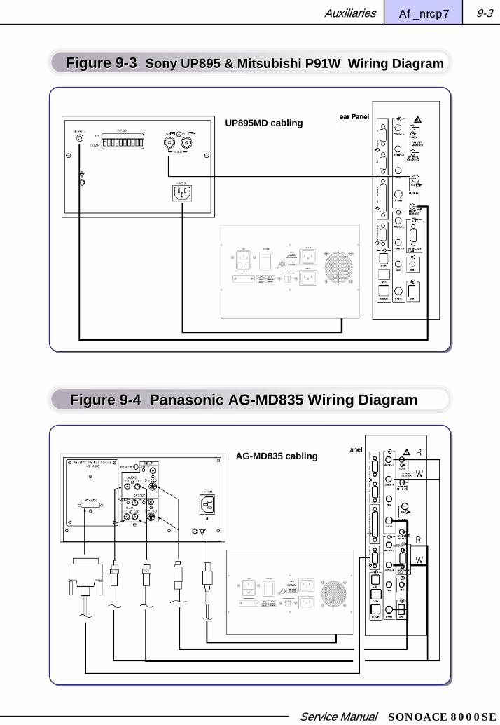
Service Manual SONOACE 8000SE
Auxiliaries Chapter 9 9-3
Figure 9Figure 9--3 3 Sony UP895 & Mitsubishi P91W Wiring DiagramSony UP895 & Mitsubishi P91W Wiring Diagram
UP895MD cabling
Figure 9Figure 9--4 Panasonic AG4 Panasonic AG--MD835 Wiring DiagramMD835 Wiring Diagram
AG-MD835 cabling

Service Manual SONOACE 8000SE
Auxiliaries Chapter 9 9-4
Auxiliary Settings The following setting values are factory setting values.
Sony UP895 SettingsSony UP895 Settings
On the DIP switch on the printer rear panel, only the first switch on the left (IMP) should be switched up, and all other switches should be switched down.
Sharpness 2
Gamma 2
Paper HD
Smoothing OFF
Contrast 7
Brightness 7
[ Table 9-1] UP895 Printer Control Settings ]

Service Manual SONOACE 8000SE
Auxiliaries Chapter 9 9-5
Sony UP21Sony UP21--MD SettingsMD Settings
The following are default setting values for the Sony UP21-MD color printer.
COL:Load Color: 1CYN – RED: 0MAG – RGB: 0YEL – BLU: 0Dark: 1Light: 0Sharpness: 8Interpol: OFFSave Color: 1 [EXEC]
LAY: NTSC Settings PAL Settings
Memory: Frame Frame
Multi Pix: 1 1
Separate: ***** *****
Window:
H Start: -24 Dots 40 Dots
V Start: -8 Dots 20 Dots
H Width: 976 Dots 840 Dots
V Width: 480 Dots 496 Dots
Save Press [EXEC] Press [EXEC]
Caption: OFF OFF
[ Table 9-2] UP21- MD Printer Settings

Service Manual SONOACE 8000SE
Auxiliaries Chapter 9 9-6
PRN:
Print QLT: 1
GAMMA: Normal
PRN Speed: Normal
Load User: 1
System Setup:
LCD. Center: 7
Baud Rate: 4800
Beep: ON
IRE.: 100
Save User: 1
Function:
Auto Live: OFF
Immed. Cap.: OFF
RM2 Func.: C&Print
Clear: ALL
Color Balance:
BAL X: 50
BAL Y: 50
BAL Step: 5
IN:
INPUT SEL:
Video: N/A
S-Video: N/A
RGB
Hue: *****
Color: *****
Gain: 0
Offset: 0
AGC: ON
OUT:
Display: OFF
RBN Remain: OFF
Source: EE
Sync on G: ON
Moni C-R: 0
Moni M-G: 0
Moni Y-B 0
[ Table 9-3] UP21- MD Printer Settings

Service Manual SONOACE 8000SE
Auxiliaries Chapter 9 9-7
Mitsubishi CP800 SettingsMitsubishi CP800 Settings
Set the RGC and Sync switch on the printer rear panel to 75 OHM.
Menus and Parameters ACCUVIX Default Settings
COLOR ADJ
BRT 7 or User’s Preference
CONT 5 or User’s Preference
R-SUB 0
G-SUB 0
B-SUB 0
CENTER PUSH
ANALOG ADJ
BRT 7
CONT 5
R-SUB 0
B-SUB 0
CENTER PUSH
INPUT
RGB
ADDITIONAL
MULTI OFF
BUZZER TONE1
MODE S
GRAD NOMAL
[ Table 9-4] CP800 Main Menu Control Settings

Service Manual SONOACE 8000SE
Auxiliaries Chapter 9 9-8
GAMMA ADJ N/A
APT NOMAL
COM OFF
MIRROR OFF
COMMENT [>]
SIZE/TIMMING
H-POSI -2
H-START FRONT
SIZE USER
SAVE PRG -6
SYSTEM SET
PAGE INC ON
LIVE SELECT DIGITAL
CONVERT ON
REMAINING OFF
REMOTE SET N/A
PREVIOUS ERROR N/A
[ Table 9-5] CP800 Main Menu Control Settings

Service Manual SONOACE 8000SE
Auxiliaries Chapter 9 9-9
Menus and Parameters ACCUVIX Default Settings
KEY SET
KEY LOCK OFF
MEM & PRN ON
MEM & STOP OFF
MEM & MONI OFF
PRN & CLR OFF
CLEAR KEY PAGE
KEEP MONI OFF
SIGNAL SET1
FIELD NOMAL
AFC OFF
SYNC EXIT
R-SUB 0
B-SUB 0
SIGNAL SET2 N/A
SIGNAL SET
DIR NOMAL
MARGIN CUT OFF
AUTO CUT ON
OP MODE 3P
[ Table 9-6] CP800 Main Menu Control Settings

Service Manual SONOACE 8000SE
Chapter 10
Configuration
Overview 10 – 1
Verifying Main PCB Locations 10 - 1
PCB Names 10 - 3
Rear I/O Connector Panel PCB Detail 10 - 7

Service Manual SONOACE 8000SE
Configuration Chapter 10 10-1
ConfigurationConfiguration
OverviewThis chapter contains instructions for verifying the main PCB locations for the SEBY system and their functions.
Verifying Main PCB Locations
Figure 10-1 is a PCB illustration showing the locations of the primary system PCBs.

Service Manual SONOACE 8000SE
Configuration Chapter 10 10-2
[Figure 10-1] Primary System PCB Locations in Card Cage

Service Manual SONOACE 8000SE
Configuration Chapter 10 10-3
PCB Names
[Figure 10 – 2] Continuous Wave Doppler (CW) PCB
[Figure 10 – 3] Digital Beamformer (BF) PCB

Service Manual SONOACE 8000SE
Configuration Chapter 10 10-4
[Figure 10 – 4] Digital Scan Converter (DSC) PCB
[Figure10 – 5] PC Carrier (PCC) PCB
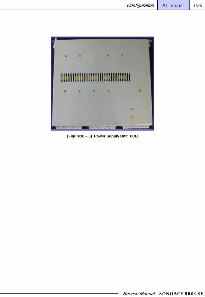
Service Manual SONOACE 8000SE
Configuration Chapter 10 10-5
[Figure10 – 6] Power Supply Unit PCB

Service Manual SONOACE 8000SE
Configuration Chapter 10 10-6
[Figure 10-7] Motherboard (Back Plane) PCB

Service Manual SONOACE 8000SE
Configuration Chapter 10 10-7
Rear I/O Connector Panel PCB Detail
Auxiliary Connection – A VCR, printer and other auxiliary devices can be connected here.
Rear Panel Input Connections
1. VHS and S-VHS VCR left and right audio Input 2. ECG 3. Microphone
4. Keyboard 5. VHS and SVHS VCR left and right audio Output
6. Patient monitor video and 9VDC power 7. B/W printer video and remote control
8. VGA monitor 9. Parallel port 10. LAN Port 11. RS-232C Port
1. VHS and S-VHS VCR left and right audio Input
2. ECG Out
5. VHS and S-VHS VCR left and right audio Output
8. VGA monitor Output
7. B/W printer video and remote control Output
3. Microphone In
9. Parallel port
11. LAN Port
12. RS-232C Port
[Figure 10-8] Rear I/O Connector Panel

Service Manual SONOACE 8000SE
Chapter 11
Parts
Ordering Parts 11-1
Part Numbers 11-2
Parts List 11-3

Service Manual SONOACE 8000SE
Parts Chapter 11 11-1
PartsParts
Ordering Parts This chapter contains information on the SEBY parts.
Please refer to the SEBY Compatibility Matrix to check the replacement parts and their software versions for each system configuration (main PCBs and specific hardware parts).
For installing and verifying system parts, please refer to the figures and part tables in this chapter.
Part numbers are indicated in the corresponding tables.
Prior to ordering parts, please verify whether the existing parts can be replaced according to the current service policy.

Service Manual SONOACE 8000SE
Parts Chapter 11 11-2
Part NumbersPART PART NAME PART DESCRIPTION
BD-340-BF-0A SEBY B/F B/D
BD-340-CW-00 SEBY CW B/D
BD-340-DSC-0A SEBY DSC B/D
BD-340-PCC-0A SEBY PCC B/D
BD-340-PSA-2P-0A SEBY PSA 2PORT B/D
BD-336-KI-0B SA8000 KEY INTERFACE B/D
BD-336-TGC-1A SA8000 TGC B/D
BD-340-KM-0A SEBY KEY/M B/D
BD-340-MTH-0A SEBY MOTHER B/D
BD-340-RL-0A SEBY REAR PANEL LEFT B/D
BD-340-RM-0A SEBY REAR PANEL MIDDLE B/D
BD-340-RR-0A SEBY REAR PANEL RIGHT B/D
BD-340-USB-0A SEBY USB B/D
BD-336-RIL-0A REAR PANNEL IF I LOWER BD
BD-336-RIU-0A REAR PANNEL IF I UPPER BD
AY-340-PWR-ADM-00 SEBY POWER AY AC-DC MODULE
AY-340-PWR-DDM-00 SEBY POWER AY DC-DC MODULE
AY-FAN-336-BACK-00 SA8000 BACK FAN CABLE AY
AY-SPEAK-8000-00 SPEAKER SA8000 AY
Track Ball AY-TB-B/58-UNIT-1-00 TRACK BALL BLACK UNIT 58MM
Monitor MNT-15-TOTOKU/SEBY-00 MONITOR 15 TOTOKU ASSY SEBY
Board
Power
Electric

Service Manual SONOACE 8000SE
Chapter 12
PROBE
Specification 12-1
Information 12-2

Service Manual SONOACE 8000SE
Probe Chapter 12 12-1
PROBEPROBE
SpecificationThis section summarizes probe specifications for the SA8000SE Ultrasound System.
Probe SpecificationsProbe SpecificationsThis section includes information on the part ordering process used by the field service engineers.
Probe Application Clinical Use
C3-7ED Abdomen,OB,GYN,Fetal Fetal,Abdomen
HL5-9ED Vascular,Extremity Small Parts,Peripheral-Vascular
EC4-9ED OB,GYN,Urology Trans-Vaginal,Trans-Rectal
Service Manual SONOACE 8000SE
Probe Chapter 12 12-2
Information
Probe InformationProbe Information
Probe Name Element No. Center Frequency Doppler Frequency
C3-7ED 128 4.5 Mhz Mhz
HL5-9ED 128 7.5 Mhz Mhz
EC4-9ED 128 6.5 Mhz Mhz

Service Manual SONOACE 8000SE
Probe Chapter 12 12-3
Probe Types, Capabilities, and AdvantagesProbe Types, Capabilities, and Advantages
TYPE Capabilities Advantages
HL5-9ED
• 2D Mode• C Mode• PWD Mode• M Mode
•Dynamic receive focus for optimal lateral resolution•Multiple transmit focal zones•Wide field of view (Trapezoidal)•High frame rate•Excellent tissue definition
C3-7ED
EC4-9ED
• 2D Mode• C Mode• PWD Mode• M Mode• Freehand • 3D Mode
•Combines the advantages of phased array and Linear•Array probes•Multiple transmit focal zones•Sector format with wide field of view at skin surface•Good lateral resolution•Dynamic receive focus•Excellent resolution and detail•Design is lightweight and easy to use

Service Manual SONOACE 8000SE
Probe Chapter 12 12-4
C3C3--7ED7ED
Probe Picture Specification
Probe Type Curved Linear Array
Center Frequency 4.5 Mhz
Radius of Curvature 50[mm]
Field of View 69,56 º
Number of Elements 128
Elements Pitch 0.474[mm]
Elevation Aperture 11[mm]
Geometric Focus 80[mm]
Application Abdomen,OB,GYN,Fetal
Heart,Renal

Service Manual SONOACE 8000SE
Probe Chapter 12 12-5
HHL5L5--9ED9ED
Probe Picture Specification
Probe Type Linear
Center Frequency 7.5 Mhz
Radius of Curvature
Field of View 38.4[mm]
Number of Elements 128
Elements Pitch 0.30[mm]
Elevation Aperture 6[mm]
Geometric Focus 20[mm]
Application Pediatric,Cardiac

Service Manual SONOACE 8000SE
Probe Chapter 12 12-6
EC4EC4--9ED9ED
Probe Picture Specification
Probe Type Endocavity
Center Frequency 6.5 Mhz
Radius of Curvature 10[mm]
Field of View 150.34 º
Number of Elements 128
Elements Pitch 0.205[mm]
Elevation Aperture 6[mm]
Elevation Focus Depth 38[mm]
Application General,OB,GYN,Urology

Service Manual SONOACE 8000SE
Chapter 13
Glossary
Acronyms and Abbreviations 13-1
Terms 13-3

Service Manual SONOACE 8000SE
Glossary Chapter 13 13-1
GlossaryGlossary
Acronyms and Abbreviations
AC Alternating Current
A Amperes
ADC Analog-to-Digital Conversion
Assy Assembly
B/W Black and White
COA Customer Order Acknowledgment
CPU Central Processing Unit
CW Continuous-Wave
DAC Digital to Analog Converter
D/A Digital -to- Analog Converter
DC Direct Current
DICOM Digital Imaging and Communications in Medicine
DR Dynamic Range
DVM Digital Volt Meter
ECG Electro Cardiogram
EMC Electro Magnetic Compatibility
EMI Electro Magnetic Interference
ESD Electrostatic Sensitive Device or Electrostatic Discharge
I-RGB Interlaced Red, Green, and Blue Video
IVT Intra-Vaginal Transducer

Service Manual SONOACE 8000SE
Glossary Chapter 13 13-2
LED Light Emitting Diode
LEP List of Effective Pages
MUX Multiplexer
NTSC National Television Standards Committee
OEM Original Equipment Manufacturer
PAL Phased Alternating Line
PC Personal Computer
PCB Printed Circuit Board
PD Phased Drive
PW Pulsed-Wave
RF Radio Frequency
RX Receive, receiver
S-VHS Super VHS, a VCR video format
TGC Time Gain Compensation
TX Transmit, transmitter
UIF User Interface
VCR Video Cassette Recorder

Service Manual SONOACE 8000SE
Glossary Chapter 13 13-3
Terms
CAUTION:
Message containing caution information to protect the product.
Digital Imaging and Communication in Medicine Electromagnetic Interference (EMI):
A standard for network communication.
This system provides devices and network communication methods that comply with the version 3.0 regulation standard for external signals and noise that may degrade the performance of the electronic devices.
I-RGB:
Interlaced, red, green, and blue video signals. This system includes the rear panel connector to support video devices that use this type of video signals.
Interlaced:
Interlaced is the current television scanning standard.
One full screen frame is generally made of 525 horizontal lines. The interlaced method scans 262.5 fields, repeatedly deflecting the scanning lines vertically. In other words, one full screen frame is made by two instances of scanning.
As a result, the screen may flicker at 30 frames per second, but the same screen will not flicker at 60 frames per second.
National Television Standards Committee Non-Interlaced:
US broadcasting standard video signal (scanning at 525 line, 60Hz).
QWERTY Keyboard:
Keyboard with the top left keys laid out in the order of QWERTY. It is to the standard computer keyboard type.
Phased Alternating Line:
It is the European video standard signal scanning: the 625 Line and 50Hz Composite Video signal format.
WARNING:
Message containing caution information to protect the user and patient from possible risks and dangers.
Service Manual SONOACE 8000SE
SONOACE 8000SE SERVICE MANUAL
EnglishRev : 1.0
Date: March 2005
Publisher: Customer Support Dept., Medison Co., Ltd.
Address: Medison Venture Tower
997-10 Daechi-dong, Gangnam-gu, Seoul, Korea
Tel : 02.2194.1000
Fax : 02.2194.1071
www.medison.com