medium voltage drives selection guide -...
TRANSCRIPT
Medium Voltage AC DrivesSelection GuidePowerFlex® 7000 • Direct-to-Drive™ Technology• Air-Cooled • Liquid-Cooled
www.klinkmann.com
2
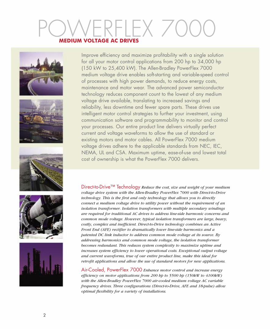
Improve efficiency and maximize profitability with a single solutionfor all your motor control applications from 200 hp to 34,000 hp(150 kW to 25,400 kW). The Allen-Bradley PowerFlex 7000medium voltage drive enables soft-starting and variable-speed controlof processes with high power demands, to reduce energy costs,maintenance and motor wear. The advanced power semiconductortechnology reduces component count to the lowest of any mediumvoltage drive available, translating to increased savings andreliability, less downtime and fewer spare parts. These drives useintelligent motor control strategies to further your investment, usingcommunication software and programmability to monitor and controlyour processes. Our entire product line delivers virtually perfectcurrent and voltage waveforms to allow the use of standard orexisting motors and motor cables. All PowerFlex 7000 mediumvoltage drives adhere to the applicable standards from NEC, IEC,NEMA, UL and CSA. Maximum uptime, ease-of-use and lowest totalcost of ownership is what the PowerFlex 7000 delivers.
Direct-to-Drive™ Technology Reduce the cost, size and weight of your mediumvoltage drive system with the Allen-Bradley PowerFlex 7000 with Direct-to-Drivetechnology. This is the first and only technology that allows you to directlyconnect a medium voltage drive to utility power without the requirement of anisolation transformer. Isolation transformers with multiple secondary windingsare required for traditional AC drives to address line-side harmonic concerns andcommon mode voltage. However, typical isolation transformers are large, heavy,costly, complex and inefficient. Direct-to-Drive technology combines an ActiveFront End (AFE) rectifier to dramatically lower line-side harmonics and apatented DC link inductor to address common mode voltage at its source. Byaddressing harmonics and common mode voltage, the isolation transformerbecomes redundant. This reduces system complexity to maximize uptime andincreases system efficiency to lower operational costs. Exceptional output voltageand current waveforms, true of our entire product line, make this ideal forretrofit applications and allow the use of standard motors for new applications.
Air-Cooled, PowerFlex 7000 Enhance motor control and increase energyefficiency on motor applications from 200 hp to 5500 hp (150kW to 4100kW)with the Allen-Bradley PowerFlex 7000 air-cooled medium voltage AC variablefrequency drives. Three configurations (Direct-to-Drive, AFE and 18-pulse) allowoptimal flexibility for a variety of installations.
POWERFLEX 7000MEDIUM VOLTAGE AC DRIVES
3
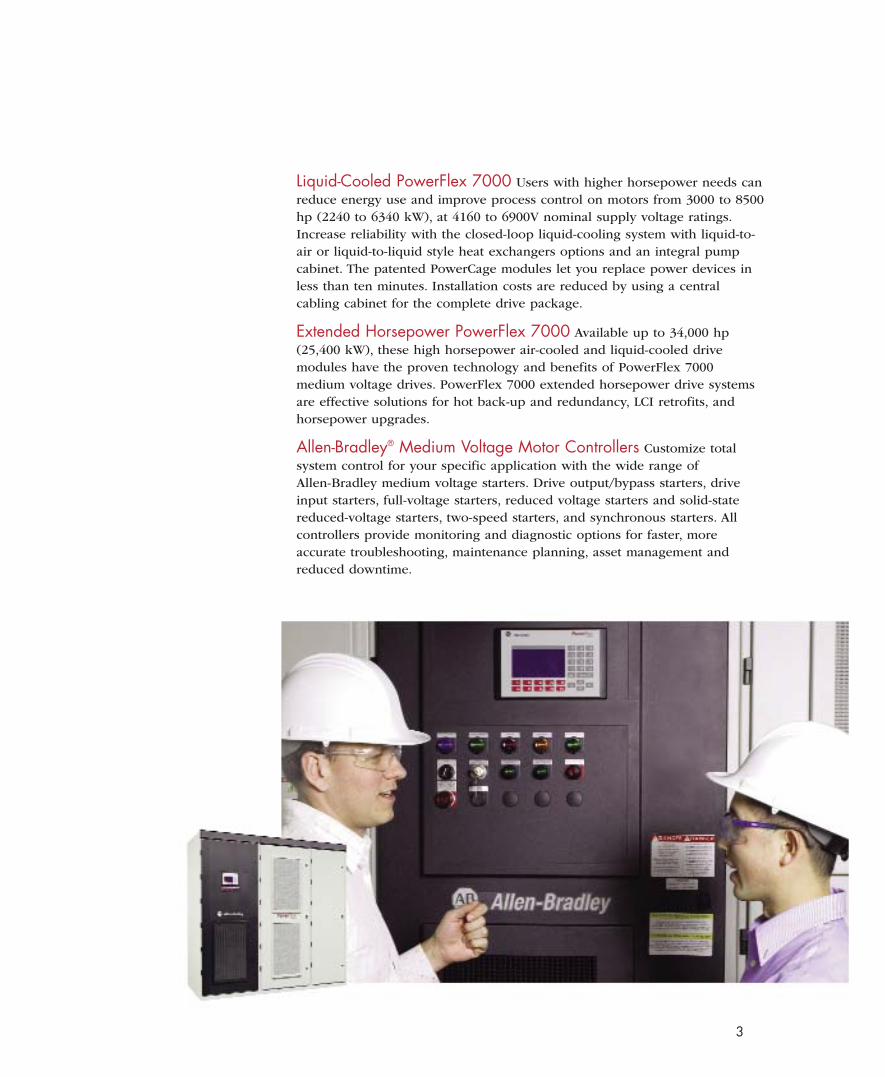
Liquid-Cooled PowerFlex 7000 Users with higher horsepower needs canreduce energy use and improve process control on motors from 3000 to 8500hp (2240 to 6340 kW), at 4160 to 6900V nominal supply voltage ratings.Increase reliability with the closed-loop liquid-cooling system with liquid-to-air or liquid-to-liquid style heat exchangers options and an integral pumpcabinet. The patented PowerCage modules let you replace power devices inless than ten minutes. Installation costs are reduced by using a centralcabling cabinet for the complete drive package.
Extended Horsepower PowerFlex 7000 Available up to 34,000 hp(25,400 kW), these high horsepower air-cooled and liquid-cooled drivemodules have the proven technology and benefits of PowerFlex 7000medium voltage drives. PowerFlex 7000 extended horsepower drive systemsare effective solutions for hot back-up and redundancy, LCI retrofits, andhorsepower upgrades.
Allen-Bradley® Medium Voltage Motor Controllers Customize totalsystem control for your specific application with the wide range ofAllen-Bradley medium voltage starters. Drive output/bypass starters, driveinput starters, full-voltage starters, reduced voltage starters and solid-statereduced-voltage starters, two-speed starters, and synchronous starters. Allcontrollers provide monitoring and diagnostic options for faster, moreaccurate troubleshooting, maintenance planning, asset management andreduced downtime.
DIRECT-TO-DRIVETECHNOLOGY
4
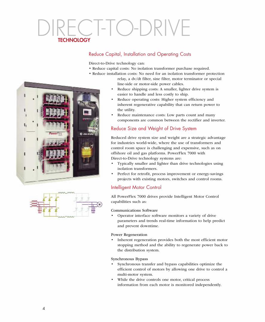
Reduce Capital, Installation and Operating Costs
Direct-to-Drive technology can:• Reduce capital costs: No isolation transformer purchase required.• Reduce installation costs: No need for an isolation transformer protection
relay, a dv/dt filter, sine filter, motor terminator or specialline-side or motor-side power cables.
• Reduce shipping costs: A smaller, lighter drive system iseasier to handle and less costly to ship.
• Reduce operating costs: Higher system efficiency andinherent regenerative capability that can return power tothe utility.
• Reduce maintenance costs: Low parts count and manycomponents are common between the rectifier and inverter.
Reduce Size and Weight of Drive System
Reduced drive system size and weight are a strategic advantagefor industries world-wide, where the use of transformers andcontrol room space is challenging and expensive, such as onoffshore oil and gas platforms. PowerFlex 7000 withDirect-to-Drive technology systems are:• Typically smaller and lighter than drive technologies using
isolation transformers.• Perfect for retrofit, process improvement or energy-savings
projects with existing motors, switches and control rooms.
Intelligent Motor Control
All PowerFlex 7000 drives provide Intelligent Motor Controlcapabilities such as:
Communications Software• Operator interface software monitors a variety of drive
parameters and trends real-time information to help predictand prevent downtime.
Power Regeneration• Inherent regeneration provides both the most efficient motor
stopping method and the ability to regenerate power back tothe distribution system.
Synchronous Bypass• Synchronous transfer and bypass capabilities optimize the
efficient control of motors by allowing one drive to control amulti-motor system.
• While the drive controls one motor, critical processinformation from each motor is monitored independently.
5
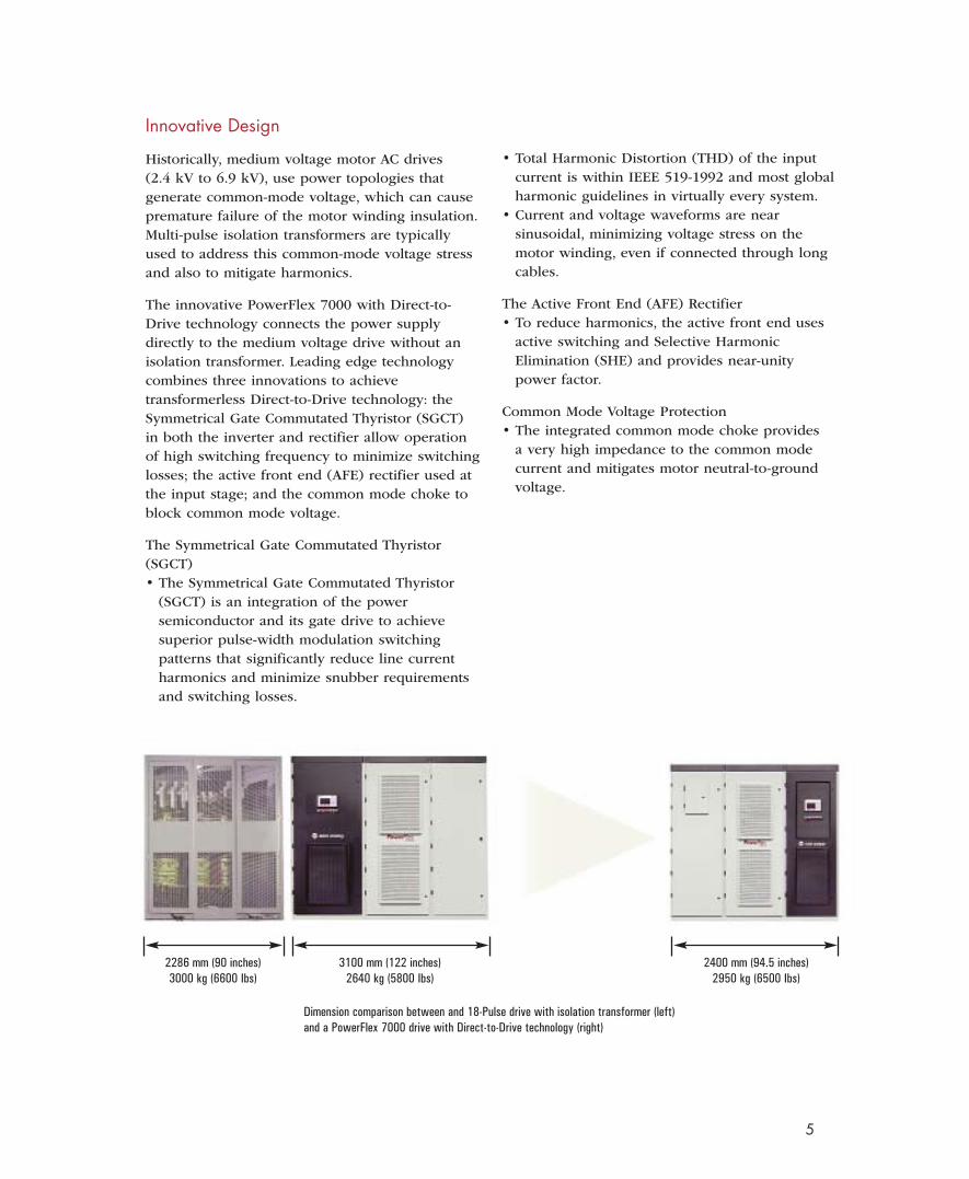
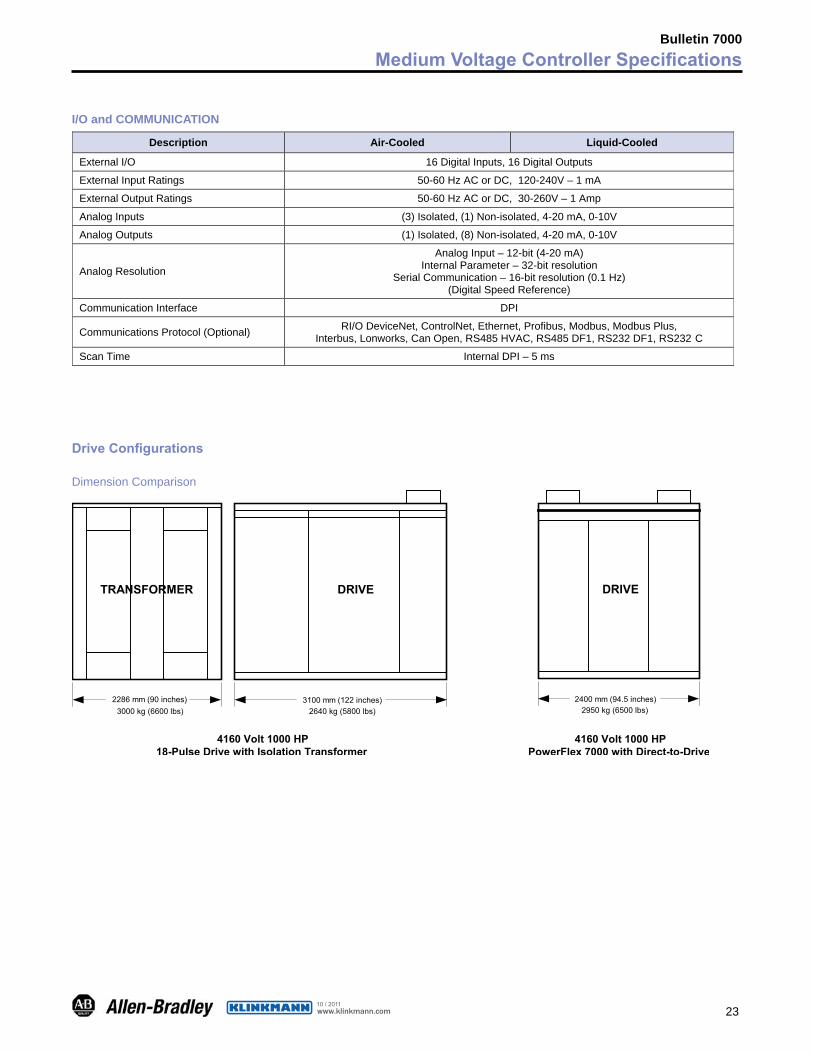
2400 mm (94.5 inches)2950 kg (6500 Ibs)
2286 mm (90 inches)3000 kg (6600 Ibs)
3100 mm (122 inches)2640 kg (5800 Ibs)
Dimension comparison between and 18-Pulse drive with isolation transformer (left)and a PowerFlex 7000 drive with Direct-to-Drive technology (right)
Innovative Design
Historically, medium voltage motor AC drives(2.4 kV to 6.9 kV), use power topologies thatgenerate common-mode voltage, which can causepremature failure of the motor winding insulation.Multi-pulse isolation transformers are typicallyused to address this common-mode voltage stressand also to mitigate harmonics.
The innovative PowerFlex 7000 with Direct-to-Drive technology connects the power supplydirectly to the medium voltage drive without anisolation transformer. Leading edge technologycombines three innovations to achievetransformerless Direct-to-Drive technology: theSymmetrical Gate Commutated Thyristor (SGCT)in both the inverter and rectifier allow operationof high switching frequency to minimize switchinglosses; the active front end (AFE) rectifier used atthe input stage; and the common mode choke toblock common mode voltage.
The Symmetrical Gate Commutated Thyristor(SGCT)• The Symmetrical Gate Commutated Thyristor
(SGCT) is an integration of the power semiconductor and its gate drive to achievesuperior pulse-width modulation switchingpatterns that significantly reduce line currentharmonics and minimize snubber requirementsand switching losses.
• Total Harmonic Distortion (THD) of the inputcurrent is within IEEE 519-1992 and most globalharmonic guidelines in virtually every system.
• Current and voltage waveforms are nearsinusoidal, minimizing voltage stress on the motor winding, even if connected through long cables.
The Active Front End (AFE) Rectifier• To reduce harmonics, the active front end uses
active switching and Selective Harmonic Elimination (SHE) and provides near-unity power factor.
Common Mode Voltage Protection• The integrated common mode choke provides
a very high impedance to the common modecurrent and mitigates motor neutral-to-groundvoltage.
6
AIR-COOLEDCOMPACT PACKAGING
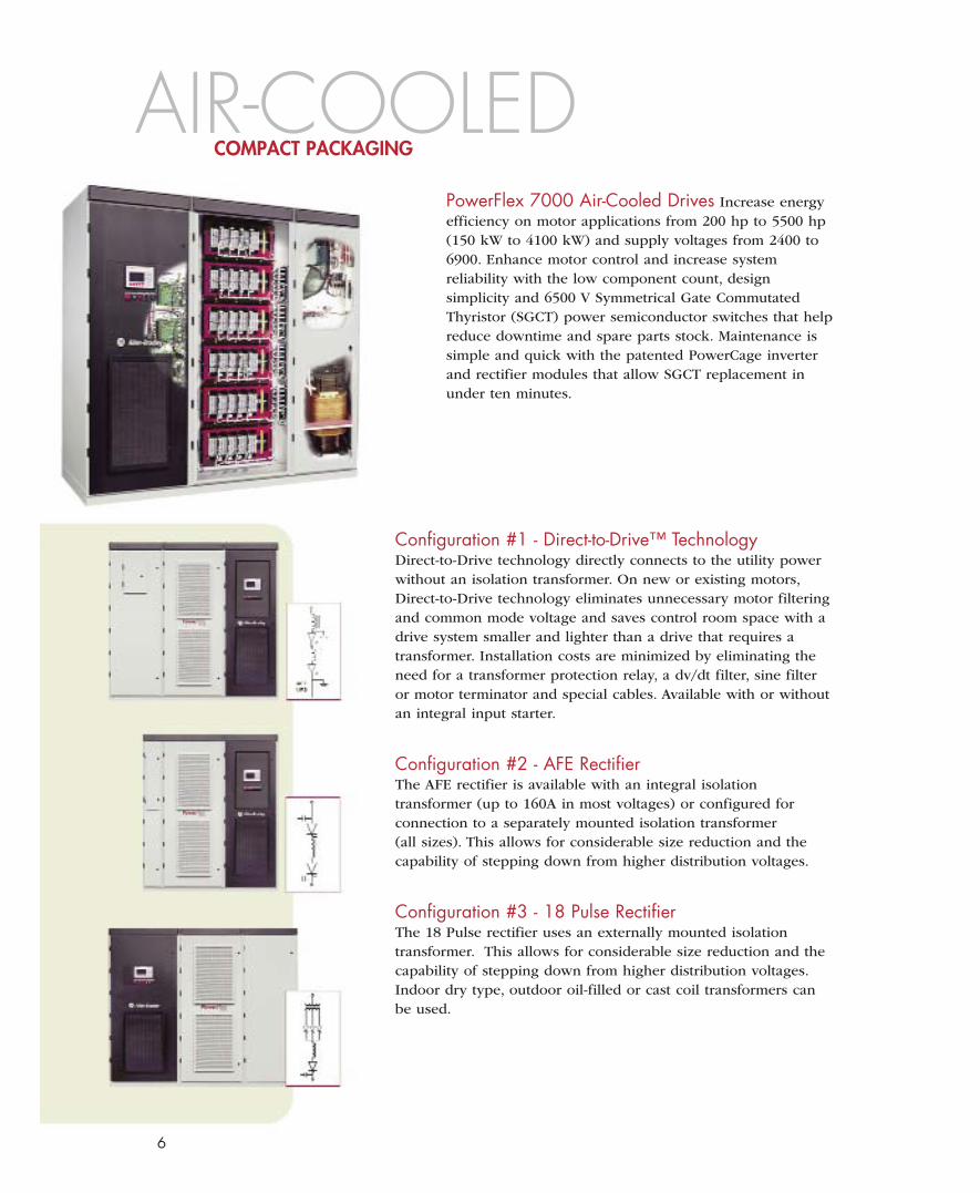
PowerFlex 7000 Air-Cooled Drives Increase energyefficiency on motor applications from 200 hp to 5500 hp(150 kW to 4100 kW) and supply voltages from 2400 to6900. Enhance motor control and increase systemreliability with the low component count, designsimplicity and 6500 V Symmetrical Gate CommutatedThyristor (SGCT) power semiconductor switches that helpreduce downtime and spare parts stock. Maintenance issimple and quick with the patented PowerCage inverterand rectifier modules that allow SGCT replacement inunder ten minutes.
Configuration #1 - Direct-to-Drive™ TechnologyDirect-to-Drive technology directly connects to the utility powerwithout an isolation transformer. On new or existing motors,Direct-to-Drive technology eliminates unnecessary motor filteringand common mode voltage and saves control room space with adrive system smaller and lighter than a drive that requires atransformer. Installation costs are minimized by eliminating theneed for a transformer protection relay, a dv/dt filter, sine filteror motor terminator and special cables. Available with or withoutan integral input starter.
Configuration #2 - AFE RectifierThe AFE rectifier is available with an integral isolationtransformer (up to 160A in most voltages) or configured forconnection to a separately mounted isolation transformer(all sizes). This allows for considerable size reduction and thecapability of stepping down from higher distribution voltages.
Configuration #3 - 18 Pulse RectifierThe 18 Pulse rectifier uses an externally mounted isolationtransformer. This allows for considerable size reduction and thecapability of stepping down from higher distribution voltages.Indoor dry type, outdoor oil-filled or cast coil transformers canbe used.
7
LIQUID-COOLEDHIGH HORSEPOWER
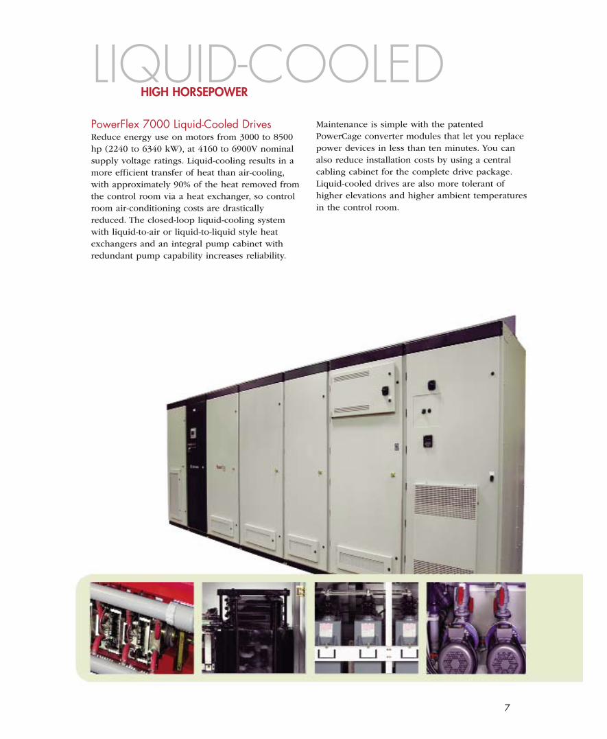
PowerFlex 7000 Liquid-Cooled DrivesReduce energy use on motors from 3000 to 8500hp (2240 to 6340 kW), at 4160 to 6900V nominalsupply voltage ratings. Liquid-cooling results in amore efficient transfer of heat than air-cooling,with approximately 90% of the heat removed fromthe control room via a heat exchanger, so controlroom air-conditioning costs are drasticallyreduced. The closed-loop liquid-cooling systemwith liquid-to-air or liquid-to-liquid style heatexchangers and an integral pump cabinet withredundant pump capability increases reliability.
Maintenance is simple with the patentedPowerCage converter modules that let you replacepower devices in less than ten minutes. You canalso reduce installation costs by using a centralcabling cabinet for the complete drive package.Liquid-cooled drives are also more tolerant ofhigher elevations and higher ambient temperaturesin the control room.
EXTENDED HORSEPOWER
8
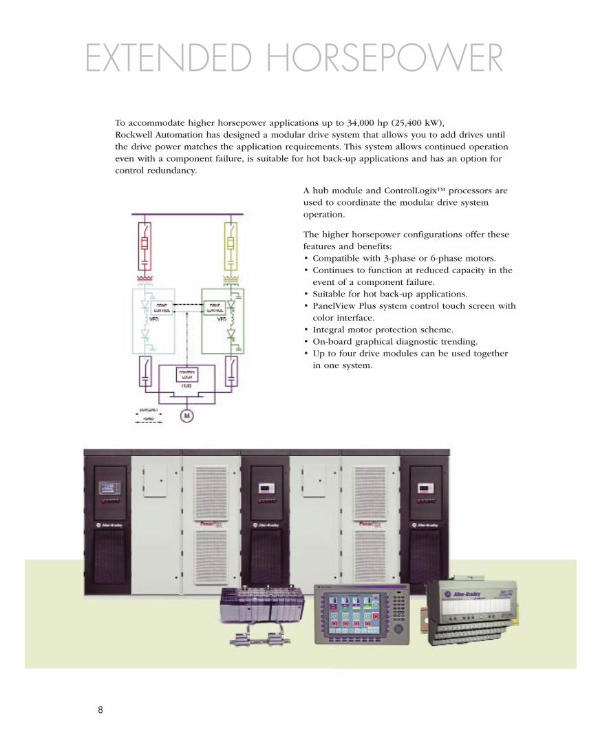
To accommodate higher horsepower applications up to 34,000 hp (25,400 kW),Rockwell Automation has designed a modular drive system that allows you to add drives untilthe drive power matches the application requirements. This system allows continued operationeven with a component failure, is suitable for hot back-up applications and has an option forcontrol redundancy.
A hub module and ControlLogix™ processors areused to coordinate the modular drive systemoperation.
The higher horsepower configurations offer thesefeatures and benefits:• Compatible with 3-phase or 6-phase motors.• Continues to function at reduced capacity in the
event of a component failure.• Suitable for hot back-up applications.• PanelView Plus system control touch screen with
color interface.• Integral motor protection scheme.• On-board graphical diagnostic trending.• Up to four drive modules can be used together
in one system.
9
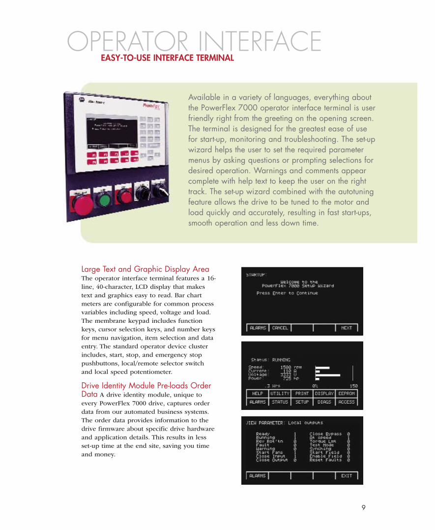
Large Text and Graphic Display AreaThe operator interface terminal features a 16-line, 40-character, LCD display that makestext and graphics easy to read. Bar chartmeters are configurable for common processvariables including speed, voltage and load.The membrane keypad includes functionkeys, cursor selection keys, and number keysfor menu navigation, item selection and dataentry. The standard operator device clusterincludes, start, stop, and emergency stoppushbuttons, local/remote selector switchand local speed potentiometer.
Drive Identity Module Pre-loads OrderData A drive identity module, unique toevery PowerFlex 7000 drive, captures orderdata from our automated business systems.The order data provides information to thedrive firmware about specific drive hardwareand application details. This results in lessset-up time at the end site, saving you timeand money.
OPERATOR INTERFACE
Available in a variety of languages, everything aboutthe PowerFlex 7000 operator interface terminal is userfriendly right from the greeting on the opening screen.The terminal is designed for the greatest ease of usefor start-up, monitoring and troubleshooting. The set-upwizard helps the user to set the required parametermenus by asking questions or prompting selections fordesired operation. Warnings and comments appearcomplete with help text to keep the user on the righttrack. The set-up wizard combined with the autotuningfeature allows the drive to be tuned to the motor andload quickly and accurately, resulting in fast start-ups,smooth operation and less down time.
EASY-TO-USE INTERFACE TERMINAL
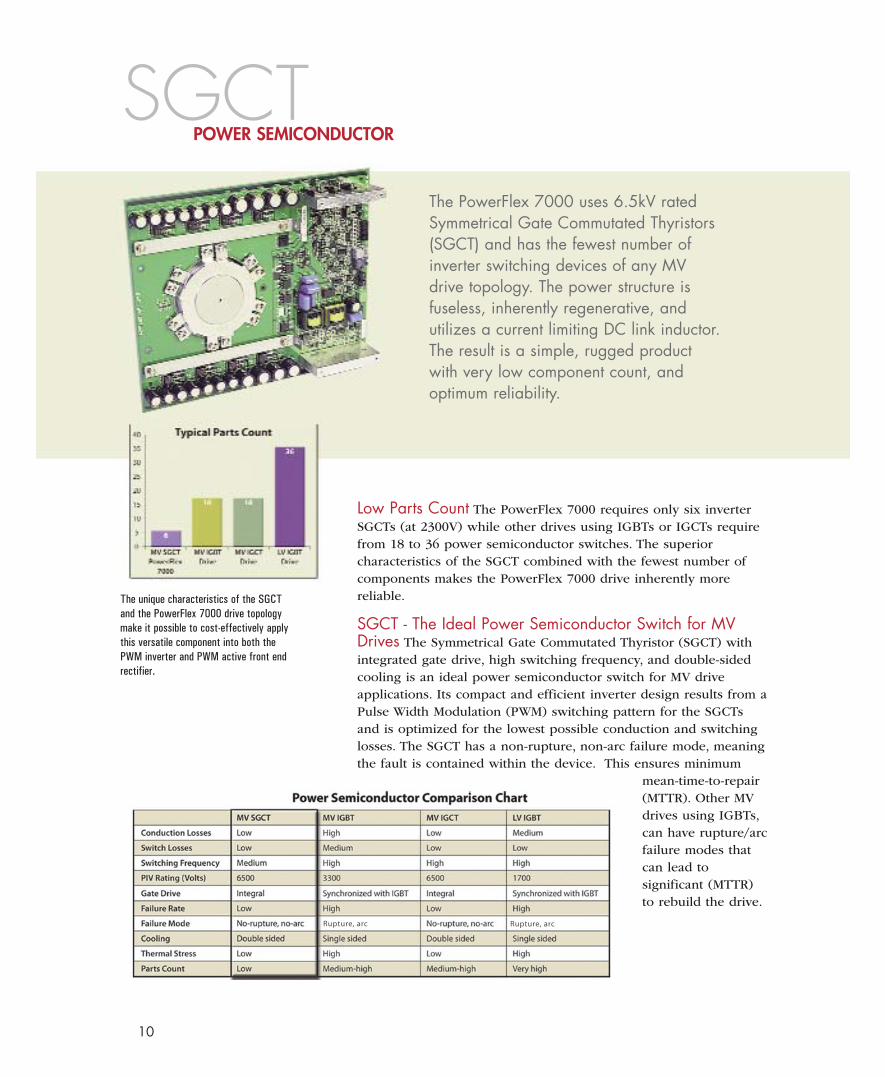
The PowerFlex 7000 uses 6.5kV ratedSymmetrical Gate Commutated Thyristors(SGCT) and has the fewest number ofinverter switching devices of any MVdrive topology. The power structure isfuseless, inherently regenerative, andutilizes a current limiting DC link inductor.The result is a simple, rugged productwith very low component count, andoptimum reliability.
Low Parts Count The PowerFlex 7000 requires only six inverterSGCTs (at 2300V) while other drives using IGBTs or IGCTs requirefrom 18 to 36 power semiconductor switches. The superiorcharacteristics of the SGCT combined with the fewest number ofcomponents makes the PowerFlex 7000 drive inherently morereliable.
SGCT - The Ideal Power Semiconductor Switch for MVDrives The Symmetrical Gate Commutated Thyristor (SGCT) withintegrated gate drive, high switching frequency, and double-sidedcooling is an ideal power semiconductor switch for MV driveapplications. Its compact and efficient inverter design results from aPulse Width Modulation (PWM) switching pattern for the SGCTsand is optimized for the lowest possible conduction and switchinglosses. The SGCT has a non-rupture, non-arc failure mode, meaningthe fault is contained within the device. This ensures minimum
mean-time-to-repair(MTTR). Other MVdrives using IGBTs,can have rupture/arcfailure modes thatcan lead tosignificant (MTTR)to rebuild the drive.
SGCTPOWER SEMICONDUCTOR
10
The unique characteristics of the SGCTand the PowerFlex 7000 drive topologymake it possible to cost-effectively applythis versatile component into both thePWM inverter and PWM active front endrectifier.
Rupture, arc Rupture, arc
11
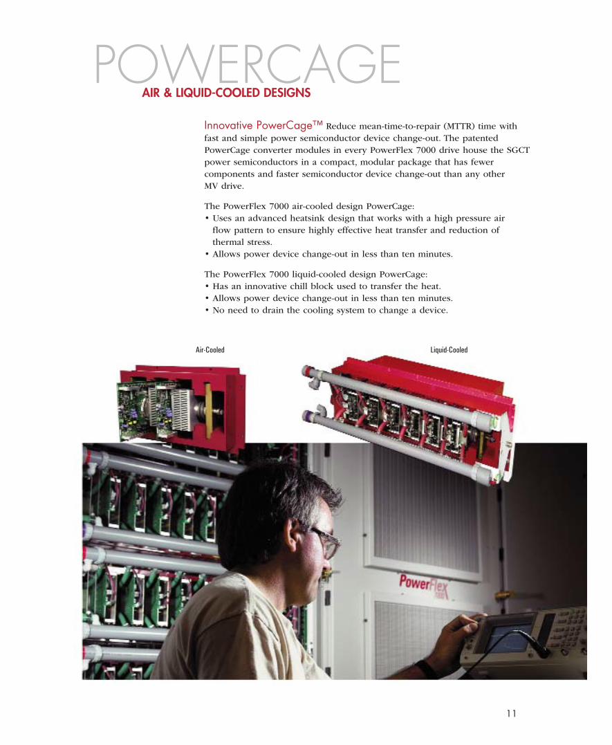
Innovative PowerCage™ Reduce mean-time-to-repair (MTTR) time withfast and simple power semiconductor device change-out. The patentedPowerCage converter modules in every PowerFlex 7000 drive house the SGCTpower semiconductors in a compact, modular package that has fewercomponents and faster semiconductor device change-out than any otherMV drive.
The PowerFlex 7000 air-cooled design PowerCage:• Uses an advanced heatsink design that works with a high pressure air
flow pattern to ensure highly effective heat transfer and reduction ofthermal stress.
• Allows power device change-out in less than ten minutes.
The PowerFlex 7000 liquid-cooled design PowerCage:• Has an innovative chill block used to transfer the heat.• Allows power device change-out in less than ten minutes.• No need to drain the cooling system to change a device.
POWERCAGEAIR & LIQUID-COOLED DESIGNS
Air-Cooled Liquid-Cooled
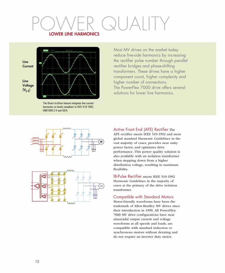
LineCurrent
LineVoltage(VL-L)
The Direct-to-Drive feature mitigates line currentharmonics to levels compliant to IEEE 519-1992,EN61000-2-4 and G5/4.
Most MV drives on the market todayreduce line-side harmonics by increasingthe rectifier pulse number through parallelrectifier bridges and phase-shiftingtransformers. These drives have a highercomponent count, higher complexity andhigher number of connections.The PowerFlex 7000 drive offers severalsolutions for lower line harmonics.
Active Front End (AFE) Rectifier TheAFE rectifier meets IEEE 519-1992 and mostglobal standard Harmonic Guidelines in thevast majority of cases, provides near unitypower factor, and optimizes driveperformance. This power quality solution isalso available with an isolation transformerwhen stepping down from a higherdistribution voltage, resulting in maximumflexibility.
l8-Pulse Rectifier meets IEEE 519-1992Harmonic Guidelines in the majority ofcases at the primary of the drive isolationtransformer.
Compatible with Standard MotorsMotor-friendly waveforms have been thetrademark of Allen-Bradley MV drives sincetheir introduction in 1990. All PowerFlex7000 MV drive configurations have nearsinusoidal output current and voltagewaveforms at all speeds and loads, arecompatible with standard induction orsynchronous motors without derating anddo not require an inverter duty motor.
POWER QUALITYLOWER LINE HARMONICS
12
13
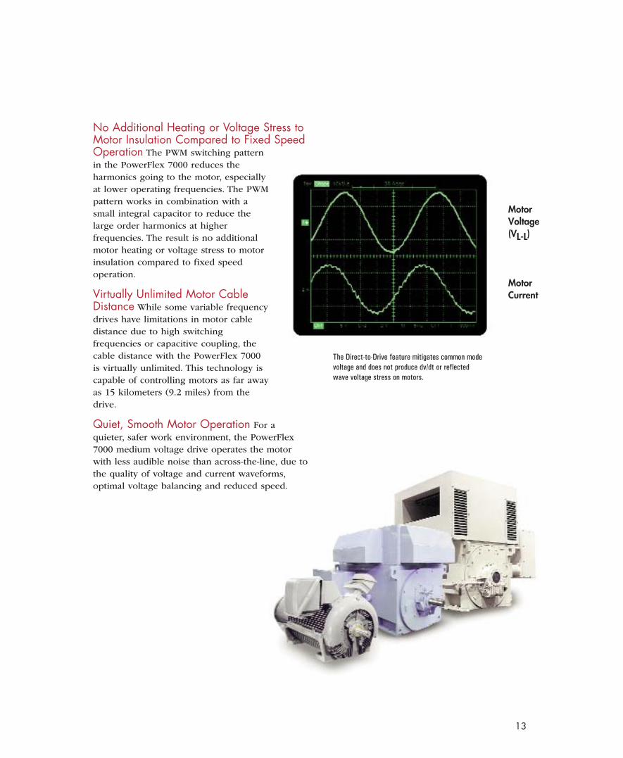
No Additional Heating or Voltage Stress toMotor Insulation Compared to Fixed SpeedOperation The PWM switching patternin the PowerFlex 7000 reduces theharmonics going to the motor, especiallyat lower operating frequencies. The PWMpattern works in combination with asmall integral capacitor to reduce thelarge order harmonics at higherfrequencies. The result is no additionalmotor heating or voltage stress to motorinsulation compared to fixed speedoperation.
Virtually Unlimited Motor CableDistance While some variable frequencydrives have limitations in motor cabledistance due to high switchingfrequencies or capacitive coupling, thecable distance with the PowerFlex 7000is virtually unlimited. This technology iscapable of controlling motors as far awayas 15 kilometers (9.2 miles) from thedrive.
Quiet, Smooth Motor Operation For aquieter, safer work environment, the PowerFlex7000 medium voltage drive operates the motorwith less audible noise than across-the-line, due tothe quality of voltage and current waveforms,optimal voltage balancing and reduced speed.
The Direct-to-Drive feature mitigates common modevoltage and does not produce dv/dt or reflectedwave voltage stress on motors.
MotorVoltage(VL-L)
MotorCurrent
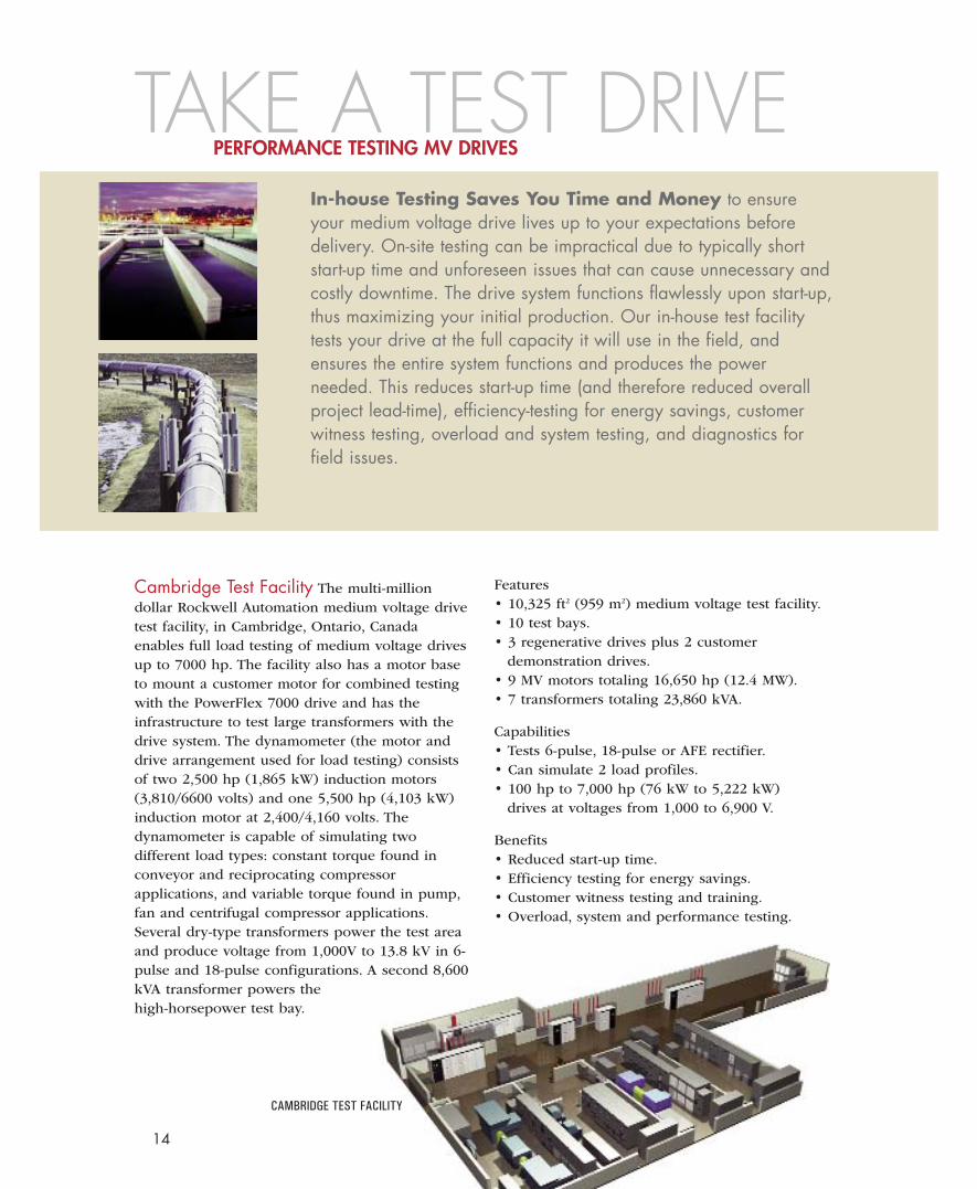
CAMBRIDGE TEST FACILITY
Cambridge Test Facility The multi-milliondollar Rockwell Automation medium voltage drivetest facility, in Cambridge, Ontario, Canadaenables full load testing of medium voltage drivesup to 7000 hp. The facility also has a motor baseto mount a customer motor for combined testingwith the PowerFlex 7000 drive and has theinfrastructure to test large transformers with thedrive system. The dynamometer (the motor anddrive arrangement used for load testing) consistsof two 2,500 hp (1,865 kW) induction motors(3,810/6600 volts) and one 5,500 hp (4,103 kW)induction motor at 2,400/4,160 volts. Thedynamometer is capable of simulating twodifferent load types: constant torque found inconveyor and reciprocating compressorapplications, and variable torque found in pump,fan and centrifugal compressor applications.Several dry-type transformers power the test areaand produce voltage from 1,000V to 13.8 kV in 6-pulse and 18-pulse configurations. A second 8,600kVA transformer powers thehigh-horsepower test bay.
In-house Testing Saves You Time and Money to ensureyour medium voltage drive lives up to your expectations beforedelivery. On-site testing can be impractical due to typically shortstart-up time and unforeseen issues that can cause unnecessary andcostly downtime. The drive system functions flawlessly upon start-up,thus maximizing your initial production. Our in-house test facilitytests your drive at the full capacity it will use in the field, andensures the entire system functions and produces the powerneeded. This reduces start-up time (and therefore reduced overallproject lead-time), efficiency-testing for energy savings, customerwitness testing, overload and system testing, and diagnostics forfield issues.
Features• 10,325 ft2 (959 m2) medium voltage test facility.• 10 test bays.• 3 regenerative drives plus 2 customer
demonstration drives.• 9 MV motors totaling 16,650 hp (12.4 MW).• 7 transformers totaling 23,860 kVA.
Capabilities• Tests 6-pulse, 18-pulse or AFE rectifier.• Can simulate 2 load profiles.• 100 hp to 7,000 hp (76 kW to 5,222 kW)
drives at voltages from 1,000 to 6,900 V.
Benefits• Reduced start-up time.• Efficiency testing for energy savings.• Customer witness testing and training.• Overload, system and performance testing.
TAKE A TEST DRIVEPERFORMANCE TESTING MV DRIVES
14
15
High Horsepower Testing at Rated Load The dynamometer (the motorand drive arrangement used for load testing) demonstrates high horsepowerliquid-cooled drives at rated load and horsepower to better serve marketssuch as the petrochemical or mining industries, or the synchronous motorretrofit market. By simulating anomalies that occur in the field, the testfacility is able to find solutions quickly, without interrupting your process.
Customer Training Learn how to program, operate and service yourPowerFlex 7000 drives during scheduled shut-downs by attending customerdrive schools in the medium voltage test facility. The four-day training,provided by qualified Rockwell Automation Product Support Engineers, giveshands-on experience with actual operating drives. This training is invaluablein keeping personnel trained on the product, and up-to-date on proper safetyand lockout procedures.
Regional MV Drive Manufacturing/Testing FacilitiesTo better support our global customers, Rockwell Automation has twoadditional manufacturing centers:1Harbin, China to support customers in the Asia-Pacific region.2Katowice, Poland to support customers in the European, Middle East and
African regions. Both facilities have extensive testing capabilities.
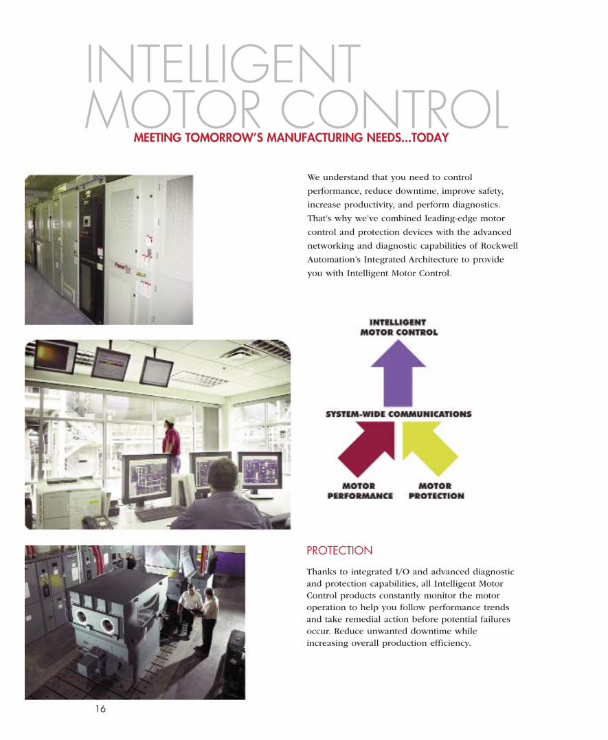
We understand that you need to control
performance, reduce downtime, improve safety,
increase productivity, and perform diagnostics.
That’s why we’ve combined leading-edge motor
control and protection devices with the advanced
networking and diagnostic capabilities of Rockwell
Automation’s Integrated Architecture to provide
you with Intelligent Motor Control.
PROTECTION
Thanks to integrated I/O and advanced diagnosticand protection capabilities, all Intelligent MotorControl products constantly monitor the motoroperation to help you follow performance trendsand take remedial action before potential failuresoccur. Reduce unwanted downtime whileincreasing overall production efficiency.
INTELLIGENTMOTOR CONTROL
MEETING TOMORROW’S MANUFACTURING NEEDS...TODAY
16
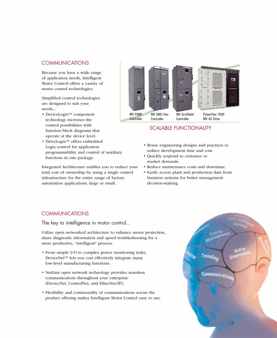
COMMUNICATIONS
Because you have a wide rangeof application needs, IntelligentMotor Control offers a variety ofmotor control technologies.
Simplified control technologiesare designed to suit yourneeds...• DeviceLogix™ component
technology increases thecontrol possibilities withfunction block diagrams thatoperate at the device level.
• DriveLogix™ offers embeddedLogix control for applicationprogrammability and control of auxiliaryfunctions in one package.
Integrated Architecture enables you to reduce yourtotal cost of ownership by using a single controlinfrastructure for the entire range of factoryautomation applications, large or small.
COMMUNICATIONS
The key to intelligence in motor control...
Utilize open networked architecture to enhance motor protection,share diagnostic information and speed troubleshooting for amore productive, "intelligent" process.
• From simple I/O to complex power monitoring tasks,DeviceNet™ lets you cost effectively integrate manylow-level manufacturing functions.
• NetLinx open network technology provides seamlesscommunications throughout your enterprise(DeviceNet, ControlNet, and EtherNet/IP).
• Flexibility and commonality of communications across theproduct offering makes Intelligent Motor Control easy to use.
SCALABLE FUNCTIONALITY
MV FVNRController
MV SMC FlexController
MV ArcShieldController
PowerFlex 7000MV AC Drive
17
• Reuse engineering designs and practices toreduce development time and cost.
• Quickly respond to customer ormarket demands.
• Reduce maintenance costs and downtime.• Easily access plant and production data from
business systems for better managementdecision-making.
18
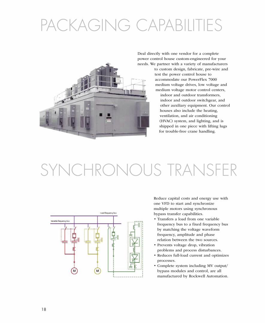
PACKAGING CAPABILITIESDeal directly with one vendor for a completepower control house custom-engineered for yourneeds. We partner with a variety of manufacturers
to custom design, fabricate, pre-wire andtest the power control house toaccommodate our PowerFlex 7000medium voltage drives, low voltage andmedium voltage motor control centers,
indoor and outdoor transformers,indoor and outdoor switchgear, andother auxiliary equipment. Our controlhouses also include the heating,ventilation, and air conditioning(HVAC) system, and lighting, and isshipped in one piece with lifting lugsfor trouble-free crane handling.
Reduce capital costs and energy use withone VFD to start and synchronizemultiple motors using synchronousbypass transfer capabilities.• Transfers a load from one variable
frequency bus to a fixed frequency busby matching the voltage waveformfrequency, amplitude and phaserelation between the two sources.
• Prevents voltage drop, vibrationproblems and process disturbances.
• Reduces full-load current and optimizesprocesses.
• Complete system including MV output/bypass modules and control, are allmanufactured by Rockwell Automation.
SYNCHRONOUS TRANSFER
19
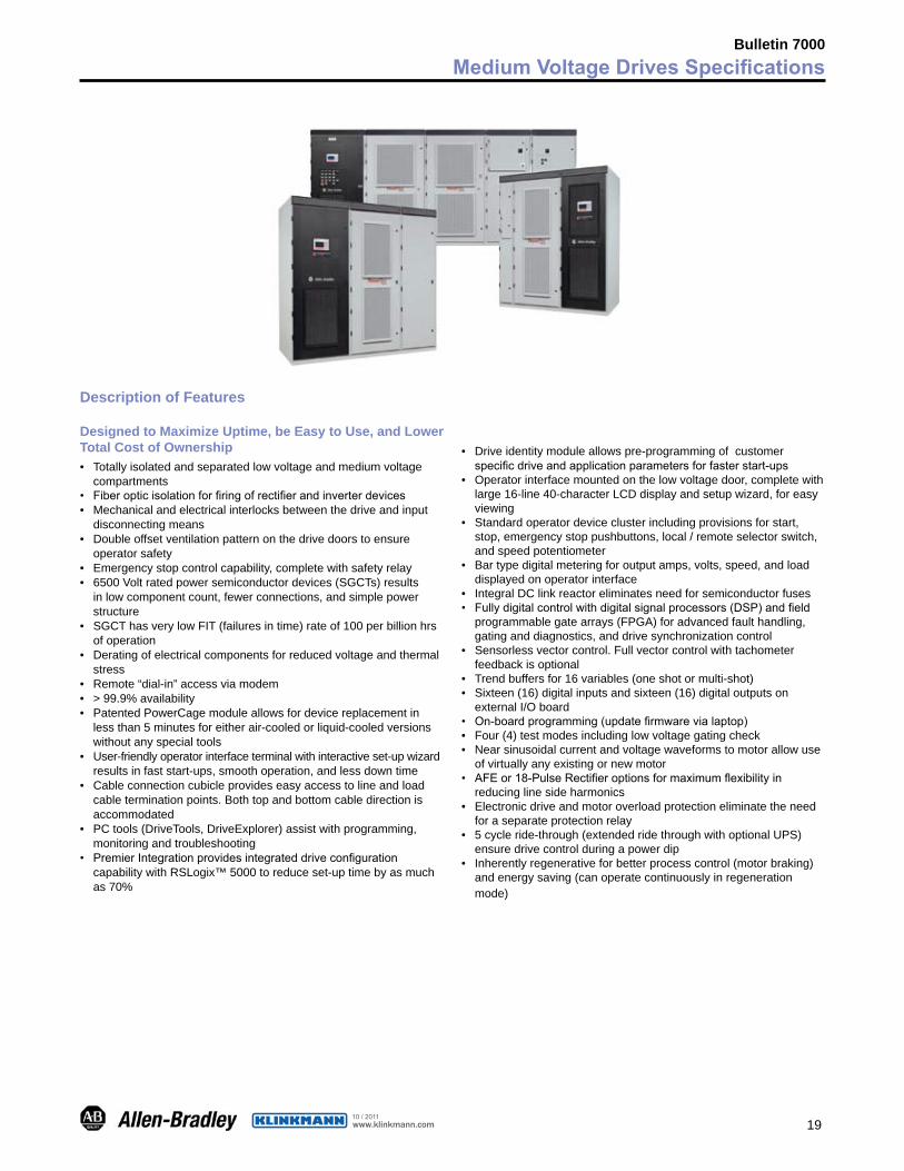
Bulletin 7000Medium Voltage Drives Specifications
Description of Features
Designed to Maximize Uptime, be Easy to Use, and Lower Total Cost of Ownership• Totallyisolatedandseparatedlowvoltageandmediumvoltage
compartments• Fiberopticisolationforfiringofrectifierandinverterdevices• Mechanicalandelectricalinterlocksbetweenthedriveandinput
disconnectingmeans• Doubleoffsetventilationpatternonthedrivedoorstoensure
operatorsafety• Emergencystopcontrolcapability,completewithsafetyrelay• 6500Voltratedpowersemiconductordevices(SGCTs)results
inlowcomponentcount,fewerconnections,andsimplepowerstructure
• SGCThasverylowFIT(failuresintime)rateof100perbillionhrsofoperation
• Deratingofelectricalcomponentsforreducedvoltageandthermalstress
• Remote“dial-in”accessviamodem• >99.9%availability• PatentedPowerCagemoduleallowsfordevicereplacementin
lessthan5minutesforeitherair-cooledorliquid-cooledversionswithoutanyspecialtools
• User-friendlyoperatorinterfaceterminalwithinteractiveset-upwizardresultsinfaststart-ups,smoothoperation,andlessdowntime
• Cableconnectioncubicleprovideseasyaccesstolineandloadcableterminationpoints.Bothtopandbottomcabledirectionisaccommodated
• PCtools(DriveTools,DriveExplorer)assistwithprogramming,monitoringandtroubleshooting
• PremierIntegrationprovidesintegrateddriveconfigurationcapabilitywithRSLogix™5000toreduceset-uptimebyasmuchas70%
• Driveidentitymoduleallowspre-programmingofcustomerspecificdriveandapplicationparametersforfasterstart-ups
• Operatorinterfacemountedonthelowvoltagedoor,completewithlarge16-line40-characterLCDdisplayandsetupwizard,foreasyviewing
• Standardoperatordeviceclusterincludingprovisionsforstart,stop,emergencystoppushbuttons,local/remoteselectorswitch,andspeedpotentiometer
• Bartypedigitalmeteringforoutputamps,volts,speed,andloaddisplayedonoperatorinterface
• IntegralDClinkreactoreliminatesneedforsemiconductorfuses• Fullydigitalcontrolwithdigitalsignalprocessors(DSP)andfield
programmablegatearrays(FPGA)foradvancedfaulthandling,gatinganddiagnostics,anddrivesynchronizationcontrol
• Sensorlessvectorcontrol.Fullvectorcontrolwithtachometerfeedbackisoptional
• Trendbuffersfor16variables(oneshotormulti-shot)• Sixteen(16)digitalinputsandsixteen(16)digitaloutputson
externalI/Oboard• On-boardprogramming(updatefirmwarevialaptop)• Four(4)testmodesincludinglowvoltagegatingcheck• Nearsinusoidalcurrentandvoltagewaveformstomotorallowuse
ofvirtuallyanyexistingornewmotor• AFEor18-PulseRectifieroptionsformaximumflexibilityin
reducinglinesideharmonics• Electronicdriveandmotoroverloadprotectioneliminatetheneed
foraseparateprotectionrelay• 5cycleride-through(extendedridethroughwithoptionalUPS)
ensuredrivecontrolduringapowerdip• Inherentlyregenerativeforbetterprocesscontrol(motorbraking)
andenergysaving(canoperatecontinuouslyinregenerationmode)
www.klinkmann.com10 / 2011
20
Bulletin 7000Medium Voltage Drive Specifications
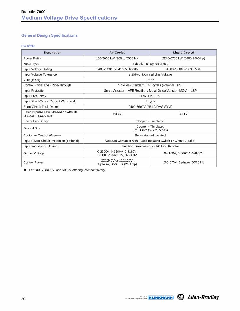
General Design Specifications
POWER
Description Air-Cooled Liquid-Cooled
Power Rating 150-3000 kW (200 to 5500 hp) 2240-6700 kW (3000-9000 hp)
Motor Type Induction or Synchronous
Input Voltage Rating 2400V, 3300V, 4160V, 6600V 4160V, 6600V, 6900V �
Input Voltage Tolerance ± 10% of Nominal Line Voltage
Voltage Sag -30%
Control Power Loss Ride-Through 5 cycles (Standard); >5 cycles (optional UPS)
Input Protection Surge Arrester – AFE Rectifier / Metal Oxide Varistor (MOV) – 18P
Input Frequency 50/60 Hz, ± 5%
Input Short-Circuit Current Withstand 5 cycle
Short-Circuit Fault Rating 2400-6600V (25 kA RMS SYM)
Basic Impulse Level (based on Altitude of 1000 m (3300 ft.)) 50 kV 45 kV
Power Bus Design Copper – Tin plated
Ground Bus Copper – Tin plated 6 x 51 mm (¼ x 2 inches)
Customer Control Wireway Separate and Isolated
Input Power Circuit Protection (optional) Vacuum Contactor with Fused Isolating Switch or Circuit Breaker
Input Impedance Device Isolation Transformer or AC Line Reactor
Output Voltage 0-2300V, 0-3300V, 0-4160V, 0-6000V, 0-6300V, 0-6600V 0-4160V, 0-6600V, 0-6900V
Control Power 220/240V or 110/120V, 1 phase, 50/60 Hz (20 Amp) 208-575V, 3 phase, 50/60 Hz
� For 2300V, 3300V, and 6900V offering, contact factory.
www.klinkmann.com10 / 2011
21
Bulletin 7000Medium Voltage Drive Specifications
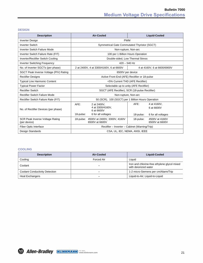
DESIGN
Description Air-Cooled Liquid-Cooled
Inverter Design PWM
Inverter Switch Symmetrical Gate Commutated Thyristor (SGCT)
Inverter Switch Failure Mode Non-rupture, Non-arc
Inverter Switch Failure Rate (FIT) 100 per 1 Billion Hours Operation
Inverter/Rectifier Switch Cooling Double-sided, Low Thermal Stress
Inverter Switching Frequency 420 – 540 Hz
No. of Inverter SGCTs (per phase) 2 at 2400V, 4 at 3300/4160V, 6 at 6600V 4 at 4160V, 6 at 6600/6900V
SGCT Peak Inverse Voltage (PIV) Rating 6500V per device
Rectifier Designs Active Front End (AFE) Rectifier or 18-pulse
Typical Line Harmonic Content <5% Current THD (AFE Rectifier)
Typical Power Factor Selectable up to unity (AFE Rectifier)
Rectifier Switch SGCT (AFE Rectifier), SCR (18-pulse Rectifier)
Rectifier Switch Failure Mode Non-rupture, Non-arc
Rectifier Switch Failure Rate (FIT) 50 (SCR), 100 (SGCT) per 1 Billion Hours Operation
No. of Rectifier Devices (per phase)
AFE: 2 at 2400V, 4 at 3300/4160V, 6 at 6600V 18-pulse: 6 for all voltages
AFE: 4 at 4160V, 6 at 6600V 18-pulse: 6 for all voltages
SCR Peak Inverse Voltage Rating (per device)
18-pulse: 4500V at 2400V, 3300V, 4160V 6500V at 6600V
18-pulse: 4500V at 4160V 6500V at 6600V
Fiber Optic Interface Rectifier – Inverter – Cabinet (Warning/Trip)
Design Standards CSA, UL, IEC, NEMA, ANSI, IEEE
COOLING
Description Air-Cooled Liquid-Cooled
Cooling Forced Air Liquid
Coolant – Iron and chlorine-free ethylene glycol mixed with deionized water
Coolant Conductivity Detection – 1-2 micro-Siemens per cm/Alarm/Trip
Heat Exchangers – Liquid-to-Air; Liquid-to-Liquid
www.klinkmann.com10 / 2011
22
Bulletin 7000Medium Voltage Drive Specifications
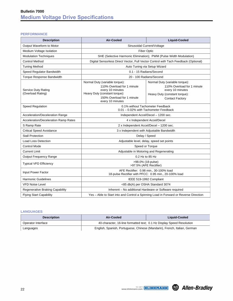
PERFORMANCE
Description Air-Cooled Liquid-Cooled
Output Waveform to Motor Sinusoidal Current/Voltage
Medium Voltage Isolation Fiber Optic
Modulation Techniques SHE (Selective Harmonic Elimination); PWM (Pulse Width Modulation)
Control Method Digital Sensorless Direct Vector, Full Vector Control with Tach Feedback (Optional)
Tuning Method Auto Tuning via Setup Wizard
Speed Regulator Bandwidth 0.1 - 15 Radians/Second
Torque Response Bandwidth 20 - 100 Radians/Second
Service Duty Rating (Overload Rating)
Normal Duty (variable torque): 110% Overload for 1 minute every 10 minutes Heavy Duty (constant torque): 150% Overload for 1 minute every 10 minutes
Normal Duty (variable torque): 110% Overload for 1 minute every 10 minutes Heavy Duty (constant torque): Contact Factory
Speed Regulation 0.1% without Tachometer Feedback 0.01 – 0.02% with Tachometer Feedback
Acceleration/Deceleration Range Independent Accel/Decel – 1200 sec.
Acceleration/Deceleration Ramp Rates 4 x Independent Accel/Decel
S Ramp Rate 2 x Independent Accel/Decel – 1200 sec.
Critical Speed Avoidance 3 x Independent with Adjustable Bandwidth
Stall Protection Delay / Speed
Load Loss Detection Adjustable level, delay, speed set points
Control Mode Speed or Torque
Current Limit Adjustable in Motoring and Regenerating
Output Frequency Range 0.2 Hz to 85 Hz
Typical VFD Efficiency >98.0% (18-pulse) >97.5% (AFE Rectifier)
Input Power Factor AFE Rectifier: 0.98 min., 30-100% load 18-pulse Rectifier with PFCC: 0.95 min., 20-100% load
Harmonic Guidelines IEEE 519-1992 Compliant
VFD Noise Level <85 db(A) per OSHA Standard 3074
Regenerative Braking Capability Inherent – No additional Hardware or Software required
Flying Start Capability Yes – Able to Start into and Control a Spinning Load in Forward or Reverse Direction
LANGUAGESDescription Air-Cooled Liquid-Cooled
Operator Interface 40-character, 16-line formatted text; 0.1 Hz Display Speed Resolution
Languages English, Spanish, Portuguese, Chinese (Mandarin), French, Italian, German
www.klinkmann.com10 / 2011
23
Bulletin 7000Medium Voltage Controller Specifications
I/O and COMMUNICATION
Description Air-Cooled Liquid-Cooled
External I/O 16 Digital Inputs, 16 Digital Outputs
External Input Ratings 50-60 Hz AC or DC, 120-240V – 1 mA
External Output Ratings 50-60 Hz AC or DC, 30-260V – 1 Amp
Analog Inputs (3) Isolated, (1) Non-isolated, 4-20 mA, 0-10V
Analog Outputs (1) Isolated, (8) Non-isolated, 4-20 mA, 0-10V
Analog Resolution
Analog Input – 12-bit (4-20 mA) Internal Parameter – 32-bit resolution
Serial Communication – 16-bit resolution (0.1 Hz) (Digital Speed Reference)
Communication Interface DPI
Communications Protocol (Optional) RI/O DeviceNet, ControlNet, Ethernet, Profibus, Modbus, Modbus Plus, Interbus, Lonworks, Can Open, RS485 HVAC, RS485 DF1, RS232 DF1, RS232 C
Scan Time Internal DPI – 5 ms
Drive Configurations
DimensionComparison
www.klinkmann.com10 / 2011

24
Drive Overview
PowerFlex 7000 “A” Frame • Aircooling • Lowendpowerrange,150-930kW(200-1250hp) • 2400to6600Vnominalsupplyvoltageratings • Compactpackagingforsmallestfootprintrequirements • Threeinputconfigurationsforoptimuminstallationflexibility: 1)Direct-to-Drive 2)AFERectifier(connectiontoseparateisolationtransformer) 3)AFERectifier(completewithintegralisolationtransformer) • Normaldutyservicerating(forvariabletorqueloads,110%overloadfor1minuteevery10minutes) • Heavydutyservicerating(forconstanttorqueloads,150%overloadfor1minuteevery10minutes) • ActiveFrontEndrectifierforlowlineharmonics,highpowerfactorandcommonalityofparts • Three(3)Cablesin/Three(3)cablesoutforlowerinstallationcosts
PowerFlex 7000 “B” Frame • Aircooling • LowandMediumpowerrange,150-4100kW(200-5500hp) • 2400to6600Vnominalsupplyvoltageratings • Normaldutyservicerating(forvariabletorqueloads,110%overloadfor1minuteevery10minutes) • Heavydutyservicerating(forconstanttorqueloads,150%overloadfor1minuteevery10minutes) • Threeinputconfigurationsforoptimuminstallationflexibility: 1)Direct-to-Drive 2)AFERectifier(forconnectiontoseparatetransformer) 3)18-pulserectifierforlowlineharmonicsandconnectiontoahighvoltagedistributionsystem • Three(3)Cablesin/Three(3)cablesout(AFErectifier) • Nine(9)Cablesin/Three(3)cablesout(18-pulserectifier)
PowerFlex 7000L “C” Frame
• Closedloopliquidcoolingsystemwithliquid-to-airorliquid-to-liquidstyleheatexchangers
• Highendpowerrange,2240-6770kW(3000-9000hp) • 4160to6600Vnominalsupplyvoltageratings • Smallintegratedpackageforhighendpowerrange • Normaldutyservicerating(forvariabletorqueloads,110%
overloadfor1minuteevery10minutes) • Heavydutyservicerating(forconstanttorqueloads,150%
overloadfor1minuteevery10minutes) • Threeinputconfigurationsforoptimuminstallationflexibility: 1)Direct-to-Drive 2)AFERectifier(forconnectiontoseparatetransformer) 3)18-pulserectifierforlowlineharmonicsandconnectionto
ahighvoltagedistributionsystem • Three(3)Cablesin/Three(3)cablesout(AFErectifier) • Nine(9)Cablesin/Three(3)cablesout(18-pulserectifier)
Bulletin 7000Medium Voltage Drive Configurations
www.klinkmann.com10 / 2011
25
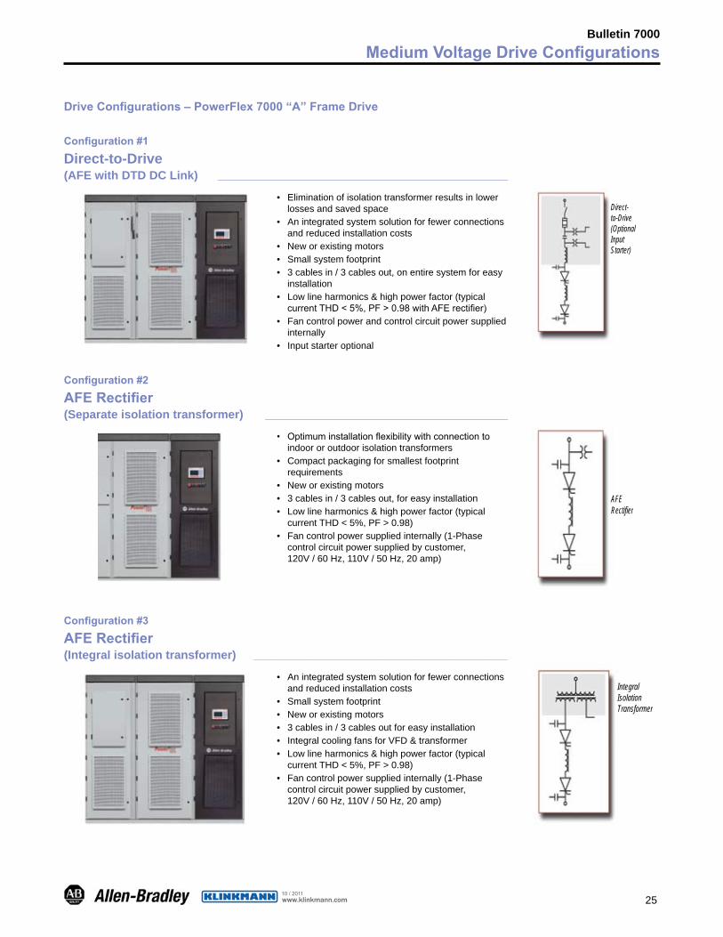
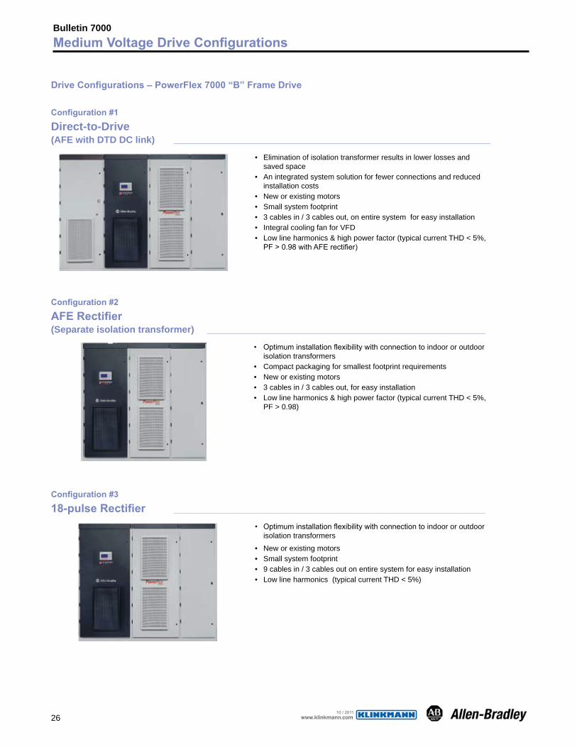
Drive Configurations – PowerFlex 7000 “A” Frame Drive
Configuration #1
Direct-to-Drive (AFE with DTD DC Link) _________________________________________________
• Eliminationofisolationtransformerresultsinlowerlossesandsavedspace
• Anintegratedsystemsolutionforfewerconnectionsandreducedinstallationcosts
• Neworexistingmotors • Smallsystemfootprint • 3cablesin/3cablesout,onentiresystemforeasy
installation • Lowlineharmonics&highpowerfactor(typical
currentTHD<5%,PF>0.98withAFErectifier) • Fancontrolpowerandcontrolcircuitpowersupplied
internally • Inputstarteroptional
Configuration #2
AFE Rectifier (Separate isolation transformer) _________________________________________
• Optimuminstallationflexibilitywithconnectiontoindoororoutdoorisolationtransformers
• Compactpackagingforsmallestfootprintrequirements
• Neworexistingmotors • 3cablesin/3cablesout,foreasyinstallation • Lowlineharmonics&highpowerfactor(typical
currentTHD<5%,PF>0.98) • Fancontrolpowersuppliedinternally(1-Phase
controlcircuitpowersuppliedbycustomer,120V/60Hz,110V/50Hz,20amp)
Configuration #3
AFE Rectifier (Integral isolation transformer) ___________________________________________
• Anintegratedsystemsolutionforfewerconnectionsandreducedinstallationcosts
• Smallsystemfootprint • Neworexistingmotors • 3cablesin/3cablesoutforeasyinstallation • IntegralcoolingfansforVFD&transformer • Lowlineharmonics&highpowerfactor(typical
currentTHD<5%,PF>0.98) • Fancontrolpowersuppliedinternally(1-Phase
controlcircuitpowersuppliedbycustomer,120V/60Hz,110V/50Hz,20amp)
Bulletin 7000Medium Voltage Drive Configurations
AFERectifier
IntegralIsolationTransformer
Direct-to-Drive(OptionalInputStarter)
www.klinkmann.com10 / 2011
26
Bulletin 7000Medium Voltage Drive Configurations
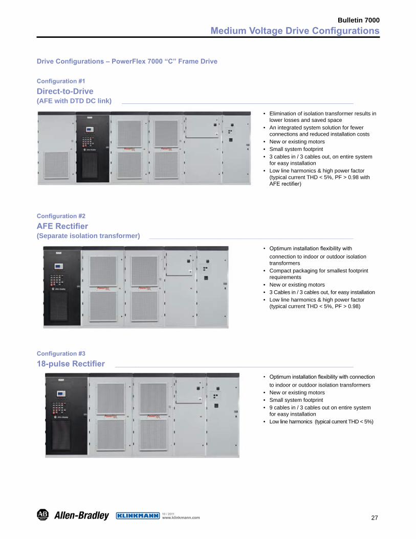
Drive Configurations – PowerFlex 7000 “B” Frame Drive
Configuration #1
Direct-to-Drive(AFE with DTD DC link) ___________________________________________________________________
• Eliminationofisolationtransformerresultsinlowerlossesandsavedspace
• Anintegratedsystemsolutionforfewerconnectionsandreducedinstallationcosts
• Neworexistingmotors • Smallsystemfootprint • 3cablesin/3cablesout,onentiresystemforeasyinstallation • IntegralcoolingfanforVFD • Lowlineharmonics&highpowerfactor(typicalcurrentTHD<5%,
PF>0.98withAFErectifier)
Configuration #2
AFE Rectifier (Separate isolation transformer) ___________________________________________________________
• Optimuminstallationflexibilitywithconnectiontoindoororoutdoorisolationtransformers
• Compactpackagingforsmallestfootprintrequirements • Neworexistingmotors • 3cablesin/3cablesout,foreasyinstallation • Lowlineharmonics&highpowerfactor(typicalcurrentTHD<5%,
PF>0.98)
Configuration #3
18-pulse Rectifier __________________________________________________________________
• Optimuminstallationflexibilitywithconnectiontoindoororoutdoorisolationtransformers
• Neworexistingmotors • Smallsystemfootprint • 9cablesin/3cablesoutonentiresystemforeasyinstallation • Lowlineharmonics(typicalcurrentTHD<5%)
www.klinkmann.com10 / 2011
27
Bulletin 7000Medium Voltage Drive Configurations
Drive Configurations – PowerFlex 7000 “C” Frame Drive
Configuration #1
Direct-to-Drive(AFE with DTD DC link) ____________________________________________________________________
• Eliminationofisolationtransformerresultsinlowerlossesandsavedspace
• Anintegratedsystemsolutionforfewerconnectionsandreducedinstallationcosts
• Neworexistingmotors • Smallsystemfootprint • 3cablesin/3cablesout,onentiresystem
foreasyinstallation • Lowlineharmonics&highpowerfactor
(typicalcurrentTHD<5%,PF>0.98withAFErectifier)
Configuration #2
AFE Rectifier (Separate isolation transformer) ____________________________________________________________
• Optimuminstallationflexibilitywithconnectiontoindoororoutdoorisolationtransformers
• Compactpackagingforsmallestfootprintrequirements
• Neworexistingmotors • 3Cablesin/3cablesout,foreasyinstallation • Lowlineharmonics&highpowerfactor
(typicalcurrentTHD<5%,PF>0.98)
Configuration #3
18-pulse Rectifier ______________________________________________________________________
• Optimuminstallationflexibilitywithconnectiontoindoororoutdoorisolationtransformers
• Neworexistingmotors • Smallsystemfootprint • 9cablesin/3cablesoutonentiresystem
foreasyinstallation • Lowlineharmonics(typicalcurrentTHD<5%)
www.klinkmann.com10 / 2011
28
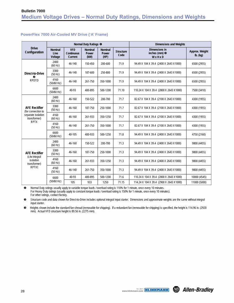
PowerFlex 7000 Air-Cooled MV Drive (‘A’ Frame)
Normal Duty Ratings � Dimensions and Weights Drive
Configuration Nominal
Line Voltage
VFD Continuous
Current
Nominal Power (kW)
Nominal Power (HP)
Structure Code
Dimensions in inches (mm) �
W x H x D
Approx. Weight lb. (kg)
2400 (60 Hz) 46-140 150-450 200-600 71.9 94.49 X 104 X 39.4 (2400 X 2643 X1000) 6500 (2955)
3300 (50 Hz) 46-140 187-600 250-800 71.9 94.49 X 104 X 39.4 (2400 X 2643 X1000) 6500 (2955)
4160 (50/60 Hz) 46-140 261-750 350-1000 71.9 94.49 X 104 X 39.4 (2400 X 2643 X1000) 6500 (2955)
Direct-to-Drive �
RPDTD
6600 (50/60 Hz) 40-93 400-895 500-1200 71.10 110.24 X 104 X 39.4 (2800 X 2643 X1000) 7500 (3410)
2400 (60 Hz) 46-160 150-522 200-700 71.7 82.67 X 104 X 39.4 (2100 X 2643 X1000) 4300 (1955)
3300 (50 Hz) 46-160 187-750 250-1000 71.7 82.67 X 104 X 39.4 (2100 X 2643 X1000) 4300 (1955)
4160 (60 Hz) 46-160 261-933 350-1250 71.7 82.67 X 104 X 39.4 (2100 X 2643 X1000) 4300 (1955)
4160 (50 Hz) 46-140 261-750 350-1000 71.7 82.67 X 104 X 39.4 (2100 X 2643 X1000) 4300 (1955)
AFE Rectifier (for connection to separate isolation
transformer) RPTX
6600 (50/60 Hz) 40-105 400-933 500-1250 71.8 94.49 X 104 X 39.4 (2400 X 2643 X1000) 4750 (2160)
2400 (60 Hz) 46-160 150-522 200-700 71.3 94.49 X 104 X 39.4 (2400 X 2643 X1000) 9800 (4455)
3300 (50 Hz) 46-160 187-750 250-1000 71.3 94.49 X 104 X 39.4 (2400 X 2643 X1000) 9800 (4455)
4160 (60 Hz) 46-160 261-933 350-1250 71.3 94.49 X 104 X 39.4 (2400 X 2643 X1000) 9800 (4455)
4160 (50 Hz) 46-140 261-750 350-1000 71.3 94.49 X 104 X 39.4 (2400 X 2643 X1000) 9800 (4455)
40-93 400-895 500-1200 71.6 110.24 X 104 X 39.4 (2800 X 2643 X1000) 10000 (4545)
AFE Rectifier (c/w integral
isolation transformer)
RPTXI
6600 (50/60 Hz) 105 933 1250 71.15 114.24 X 104 X 39.4 (2900 X 2643 X1000) 11000 (5000)
� Normal Duty ratings usually apply to variable torque loads / overload rating is 110% for 1 minute, once every 10 minutes. For Heavy Duty ratings (usually apply to constant torque loads / overload rating is 150% for 1 minute, once every 10 minutes). For other ratings, contact factory.
� Structure code and data shown for Direct-to-Drive includes optional integral input starter. Dimensions and approximate weights are the same without integral input starter.
� Heights shown include the standard fan shroud (removable for shipping). If a redundant fan (removable for shipping) is specified, the height is 114.96 in. (2920 mm). Actual VFD structure height is 89.56 in. (2275 mm).
Bulletin 7000Medium Voltage Drives – Normal Duty Ratings, Dimensions and Weights
www.klinkmann.com10 / 2011
29
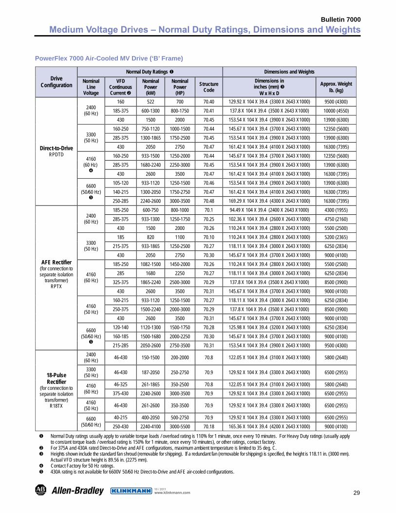
Bulletin 7000Medium Voltage Drives – Normal Duty Ratings, Dimensions and Weights
PowerFlex 7000 Air-Cooled MV Drive (‘B’ Frame)
Normal Duty Ratings � Dimensions and Weights Drive
Configuration Nominal
Line Voltage
VFD Continuous Current �
Nominal Power (kW)
Nominal Power (HP)
Structure Code
Dimensions in inches (mm) �
W x H x D
Approx. Weight lb. (kg)
160 522 700 70.40 129.92 X 104 X 39.4 (3300 X 2643 X1000) 9500 (4300)
185-375 600-1300 800-1750 70.41 137.8 X 104 X 39.4 (3500 X 2643 X1000) 10000 (4550) 2400 (60 Hz)
430 1500 2000 70.45 153.54 X 104 X 39.4 (3900 X 2643 X1000) 13900 (6300) 160-250 750-1120 1000-1500 70.44 145.67 X 104 X 39.4 (3700 X 2643 X1000) 12350 (5600) 285-375 1300-1865 1750-2500 70.45 153.54 X 104 X 39.4 (3900 X 2643 X1000) 13900 (6300) 3300
(50 Hz) 430 2050 2750 70.47 161.42 X 104 X 39.4 (4100 X 2643 X1000) 16300 (7395)
160-250 933-1500 1250-2000 70.44 145.67 X 104 X 39.4 (3700 X 2643 X1000) 12350 (5600) 285-375 1680-2240 2250-3000 70.45 153.54 X 104 X 39.4 (3900 X 2643 X1000) 13900 (6300)
4160 (60 Hz) � 430 2600 3500 70.47 161.42 X 104 X 39.4 (4100 X 2643 X1000) 16300 (7395)
105-120 933-1120 1250-1500 70.46 153.54 X 104 X 39.4 (3900 X 2643 X1000) 13900 (6300) 140-215 1300-2050 1750-2750 70.47 161.42 X 104 X 39.4 (4100 X 2643 X1000) 16300 (7395)
Direct-to-Drive RPDTD
6600 (50/60 Hz) � 250-285 2240-2600 3000-3500 70.48 169.29 X 104 X 39.4 (4300 X 2643 X1000) 16300 (7395)
185-250 600-750 800-1000 70.1 94.49 X 104 X 39.4 (2400 X 2643 X1000) 4300 (1955)
285-375 933-1300 1250-1750 70.25 102.36 X 104 X 39.4 (2600 X 2643 X1000) 4750 (2160) 2400 (60 Hz)
430 1500 2000 70.26 110.24 X 104 X 39.4 (2800 X 2643 X1000) 5500 (2500) 185 820 1100 70.10 110.24 X 104 X 39.4 (2800 X 2643 X1000) 5200 (2365)
215-375 933-1865 1250-2500 70.27 118.11 X 104 X 39.4 (3000 X 2643 X1000) 6250 (2834) 3300 (50 Hz)
430 2050 2750 70.30 145.67 X 104 X 39.4 (3700 X 2643 X1000) 9000 (4100) 185-250 1082-1500 1450-2000 70.26 110.24 X 104 X 39.4 (2800 X 2643 X1000) 5500 (2500)
285 1680 2250 70.27 118.11 X 104 X 39.4 (3000 X 2643 X1000) 6250 (2834) 325-375 1865-2240 2500-3000 70.29 137.8 X 104 X 39.4 (3500 X 2643 X1000) 8500 (3900)
4160 (60 Hz)
430 2600 3500 70.31 145.67 X 104 X 39.4 (3700 X 2643 X1000) 9000 (4100) 160-215 933-1120 1250-1500 70.27 118.11 X 104 X 39.4 (3000 X 2643 X1000) 6250 (2834) 250-375 1500-2240 2000-3000 70.29 137.8 X 104 X 39.4 (3500 X 2643 X1000) 8500 (3900) 4160
(50 Hz) 430 2600 3500 70.31 145.67 X 104 X 39.4 (3700 X 2643 X1000) 9000 (4100)
120-140 1120-1300 1500-1750 70.28 125.98 X 104 X 39.4 (3200 X 2643 X1000) 6250 (2834) 160-185 1500-1680 2000-2250 70.30 145.67 X 104 X 39.4 (3700 X 2643 X1000) 9000 (4100)
AFE Rectifier (for connection to separate isolation
transformer) RPTX
6600 (50/60 Hz) � 215-285 2050-2600 2750-3500 70.31 153.54 X 104 X 39.4 (3900 X 2643 X1000) 9500 (4300)
2400 (60 Hz) 46-430 150-1500 200-2000 70.8 122.05 X 104 X 39.4 (3100 X 2643 X1000) 5800 (2640)
3300 (50 Hz) 46-430 187-2050 250-2750 70.9 129.92 X 104 X 39.4 (3300 X 2643 X1000) 6500 (2955)
46-325 261-1865 350-2500 70.8 122.05 X 104 X 39.4 (3100 X 2643 X1000) 5800 (2640) 4160 (60 Hz) 375-430 2240-2600 3000-3500 70.9 129.92 X 104 X 39.4 (3300 X 2643 X1000) 6500 (2955) 4160
(50 Hz) 46-430 261-2600 350-3500 70.9 129.92 X 104 X 39.4 (3300 X 2643 X1000) 6500 (2955)
40-215 400-2050 500-2750 70.9 129.92 X 104 X 39.4 (3300 X 2643 X1000) 6500 (2955)
18-Pulse Rectifier
(for connection to separate isolation
transformer) R18TX
6600 (50/60 Hz) 250-430 2240-4100 3000-5500 70.18 165.36 X 104 X 39.4 (4200 X 2643 X1000) 9000 (4100)
� Normal Duty ratings usually apply to variable torque loads / overload rating is 110% for 1 minute, once every 10 minutes. For Heavy Duty ratings (usually apply to constant torque loads / overload rating is 150% for 1 minute, once every 10 minutes), or other ratings, contact factory.
� For 375A and 430A rated Direct-to-Drive and AFE configurations, maximum ambient temperature is limited to 35 deg. C. � Heights shown include the standard fan shroud (removable for shipping). If a redundant fan (removable for shipping) is specified, the height is 118.11 in. (3000 mm).
Actual VFD structure height is 89.56 in. (2275 mm). � Contact Factory for 50 Hz ratings. � 430A rating is not available for 6600V 50/60 Hz Direct-to-Drive and AFE air-cooled configurations.
www.klinkmann.com10 / 2011
30
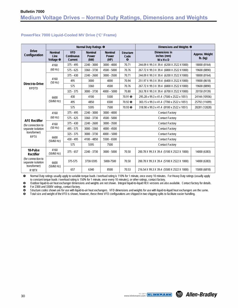
PowerFlex 7000 Liquid-Cooled MV Drive (‘C’ Frame)
Normal Duty Ratings � Dimensions and Weights � Drive
Configuration Nominal
Line Voltage �
VFD Continuous
Current
Nominal Power (kW)
Nominal Power (HP)
Structure Code �
Dimensions in inches (mm)
W x H x D
Approx. Weight lb. (kg)
375 - 495 2240 - 3000 3000 - 4000 70.71 244.09 X 99.3 X 39.4 (6200 X 2522 X1000) 18000 (8164) 4160 (60 Hz) 575 - 625 3360 - 3730 4500 - 5000 70.76 267.72 X 99.3 X 39.4 (6800 X 2522 X1000) 19600 (8890)
375 - 430 2240 - 2600 3000 - 3500 70.71 244.09 X 99.3 X 39.4 (6200 X 2522 X1000) 18000 (8164) 495 3000 4000 70.94 251.97 X 99.3 X 39.4 (6400 X 2522 X1000) 19000 (8618) 4160
(50 Hz) 575 3360 4500 70.76 267.72 X 99.3 X 39.4 (6800 X 2522 X1000) 19600 (8890)
325 - 375 3000 - 3730 4000 – 5000 70.80 263.78 X 99.3 X 39.4 (6700 X 2522 X1000) 20150 (9139) 430 4100 5500 70.91 � 295.28 x 99.3 x 41.4 (7500 x 2522 x 1051) 24144 (10936) 495 4850 6500 70.92 � 303.15 x 99.3 x 41.4 (7700 x 2522 x 1051) 25792 (11699)
Direct-to-Drive RPDTD
6600 (50/60 Hz)
575 5595 7500 70.93 � 318.90 x 99.3 x 41.4 (8100 x 2522 x 1051) 28281 (12828) 375 - 495 2240 - 3000 3000 - 4000 Contact Factory 4160
(60 Hz) 575 - 625 3360 - 3730 4500 - 5000 Contact Factory 375 - 430 2240 - 2600 3000 - 3500 Contact Factory 4160
(50 Hz) 495 - 575 3000 - 3360 4000 - 4500 Contact Factory 325 - 375 3000 - 3730 4000 – 5000 Contact Factory 430 - 495 4100 - 4850 5500 - 6500 Contact Factory
AFE Rectifier (for connection to separate isolation
transformer) RPTX 6600
(50/60 Hz) 575 5595 7500 Contact Factory
4160 (50/60 Hz) 375 - 657 2240 - 3730 3000 - 5000 70.50 200.78 X 99.3 X 39.4 (5100 X 2522 X 1000) 14000 (6383)
375-575 3730-5595 5000-7500 70.50 200.78 X 99.3 X 39.4 (5100 X 2522 X 1000) 14000 (6383)
18-Pulse Rectifier
(for connection to separate isolation
transformer) R18TX
6600 (50/60 Hz)
657 6340 8500 70.53 216.54 X 99.3 X 39.4 (5500 X 2522 X 1000) 15000 (6818)
� Normal Duty ratings usually apply to variable torque loads / overload rating is 110% for 1 minute, once every 10 minutes. For Heavy Duty ratings (usually apply to constant torque loads / overload rating is 150% for 1 minute, once every 10 minutes), or other ratings, contact factory.
� Outdoor liquid-to-air heat exchanger dimensions and weights are not shown. Integral liquid-to-liquid HEX versions are also available. Contact factory for details. � For 2300 and 3300V ratings, contact factory. � Structure codes shown are for use with liquid-to-air heat exchangers. VFD dimensions and weights for use with liquid-to-liquid heat exchangers are the same. � Total size and weight of the VFD is shown, however, these three VFD configurations are shipped in two shipping splits to facilitate easier handling.
Bulletin 7000Medium Voltage Drives – Normal Duty Ratings, Dimensions and Weights
www.klinkmann.com10 / 2011
31
Bulletin 7000Medium Voltage Drives Topology
Topology
Rectifier Design Selection Therearetwobasicrectifierconfigurations(AFEand18-Pulse)offeredasoptionsforthePowerFlex7000.Itisadvantageouswhenselectingarectifierdesigntohaveagoodunderstandingofwhatthecustomer’sneedsandlimitationsarewithregardstopowerfactor,spacerequirements,harmonicspecifications,andcost,etc.Bothoptionsofferefficiency,motorprotection,energysavings,andoptimizationofpowerqualityinvaryingdegrees.BothoftheseoptionscomplywiththerecommendedIEEE519-1992requirementsregardingharmonicdistortioninvirtuallyeverypowersystem.
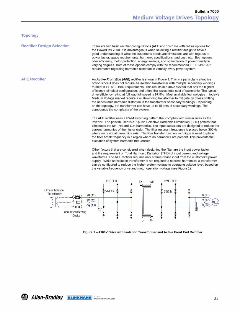
AFE Rectifier AnActive Front End (AFE) rectifierisshowninFigure1.ThisisaparticularlyattractiveoptionsinceitdoesnotrequireanisolationtransformerwithmultiplesecondarywindingstomeetIEEE519-1992requirements.Thisresultsinadrivesystemthathasthehighestefficiency,simplestconfiguration,andoffersthelowesttotalcostofownership.Thetypicaldriveefficiencyratingatfullloadfullspeedis97.5%.Mostavailabletechnologiesintoday’sMediumVoltagemarketrequireamulti-windingtransformertomitigatebyphaseshiftingtheundesirableharmonicdistortioninthetransformersecondarywindings.Dependingonthetopology,thetransformercanhaveupto15setsofsecondarywindings.Thiscompoundsthecomplexityofthesystem.
TheAFErectifierusesaPWMswitchingpatternthatcomplieswithsimilarrulesastheinverter.Thepatternusedisa7-pulseSelectiveHarmonicElimination(SHE)patternthateliminatesthe5th,7thand11thharmonics.Theinputcapacitorsaredesignedtoreducethecurrentharmonicsofthehigherorder.Thefilterresonantfrequencyisplacedbelow300Hzwherenoresidualharmonicsexist.Thefiltertransferfunctiontechniqueisusedtoplacethefilterbreakfrequencyinaregionwherenoharmonicsarepresent.Thispreventstheexcitationofsystemharmonicfrequencies.
OtherfactorsthatareconsideredwhendesigningthefilteraretheinputpowerfactorandtherequirementonTotalHarmonicDistortion(THD)ofinputcurrentandvoltagewaveforms.TheAFErectifierrequiresonlyathree-phaseinputfromthecustomer’spowersupply.Whileanisolationtransformerisnotrequiredtoaddressharmonics,atransformercanbeconfiguredtoreducethehighersystemvoltagetooperatingvoltagelevel,basedonthevariablefrequencydriveandmotoroperationvoltage(seeFigure1).
2U (X1)2V (X2)2W (X3)
3 Phase Isolation Transformer
Input Disconnecting Device
RECTIFIER
L- M-
L+ M+ INVERTER
U (T1)V (T2)
W (T3)
SGCTs SGCTs
Figure 1 – 4160V Drive with Isolation Transformer and Active Front End Rectifier
www.klinkmann.com10 / 2011
32
Bulletin 7000Medium Voltage Drives Topology
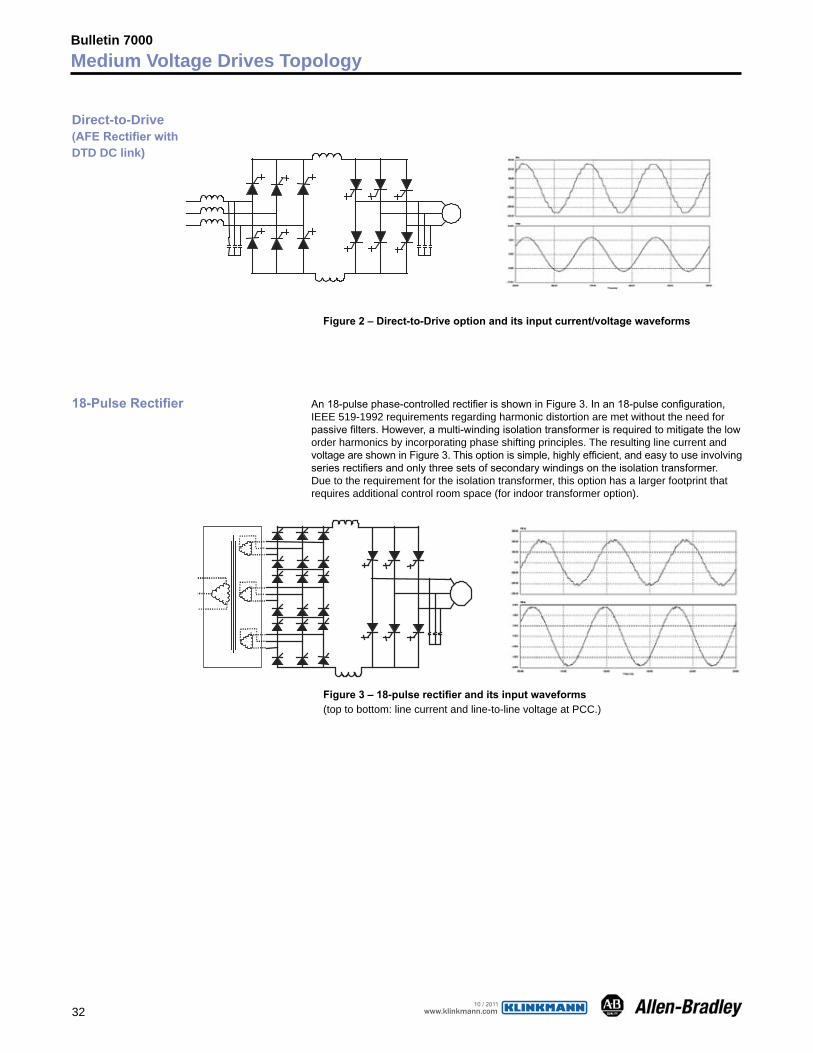
Figure 2 – Direct-to-Drive option and its input current/voltage waveforms
18-Pulse Rectifier An18-pulsephase-controlledrectifierisshowninFigure3.Inan18-pulseconfiguration,IEEE519-1992requirementsregardingharmonicdistortionaremetwithouttheneedforpassivefilters.However,amulti-windingisolationtransformerisrequiredtomitigatetheloworderharmonicsbyincorporatingphaseshiftingprinciples.TheresultinglinecurrentandvoltageareshowninFigure3.Thisoptionissimple,highlyefficient,andeasytouseinvolvingseriesrectifiersandonlythreesetsofsecondarywindingsontheisolationtransformer.Duetotherequirementfortheisolationtransformer,thisoptionhasalargerfootprintthatrequiresadditionalcontrolroomspace(forindoortransformeroption).
Figure 3 – 18-pulse rectifier and its input waveforms (toptobottom:linecurrentandline-to-linevoltageatPCC.)
Direct-to-Drive(AFE Rectifier withDTD DC link)
www.klinkmann.com10 / 2011
33
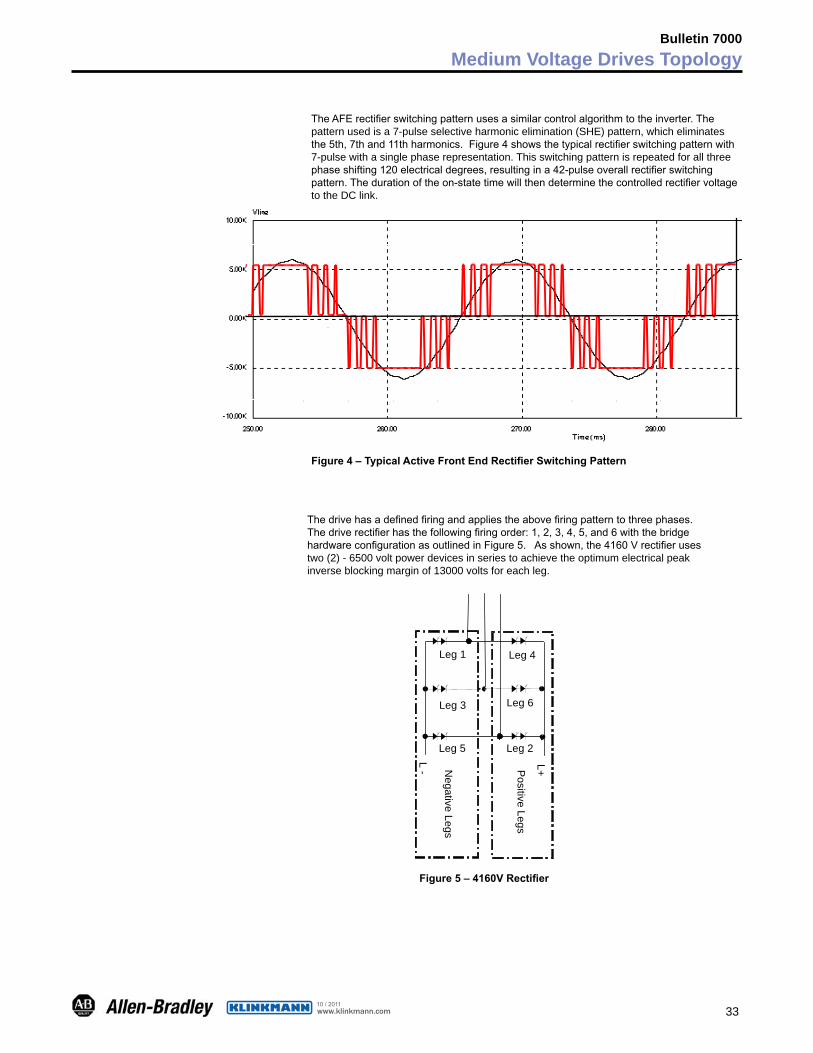
TheAFErectifierswitchingpatternusesasimilarcontrolalgorithmtotheinverter.Thepatternusedisa7-pulseselectiveharmonicelimination(SHE)pattern,whicheliminatesthe5th,7thand11thharmonics.Figure4showsthetypicalrectifierswitchingpatternwith7-pulsewithasinglephaserepresentation.Thisswitchingpatternisrepeatedforallthreephaseshifting120electricaldegrees,resultingina42-pulseoverallrectifierswitchingpattern.Thedurationoftheon-statetimewillthendeterminethecontrolledrectifiervoltagetotheDClink.
Figure 4 – Typical Active Front End Rectifier Switching Pattern
Thedrivehasadefinedfiringandappliestheabovefiringpatterntothreephases.
Thedriverectifierhasthefollowingfiringorder:1,2,3,4,5,and6withthebridgehardwareconfigurationasoutlinedinFigure5.Asshown,the4160Vrectifierusestwo(2)-6500voltpowerdevicesinseriestoachievetheoptimumelectricalpeakinverseblockingmarginof13000voltsforeachleg.
L+
L -
Leg 1
Leg 2
Leg 3
Leg 4
Leg 5
Leg 6
Positive Legs
Negative Legs
Figure 5 – 4160V Rectifier
Bulletin 7000Medium Voltage Drives Topology
www.klinkmann.com10 / 2011
34
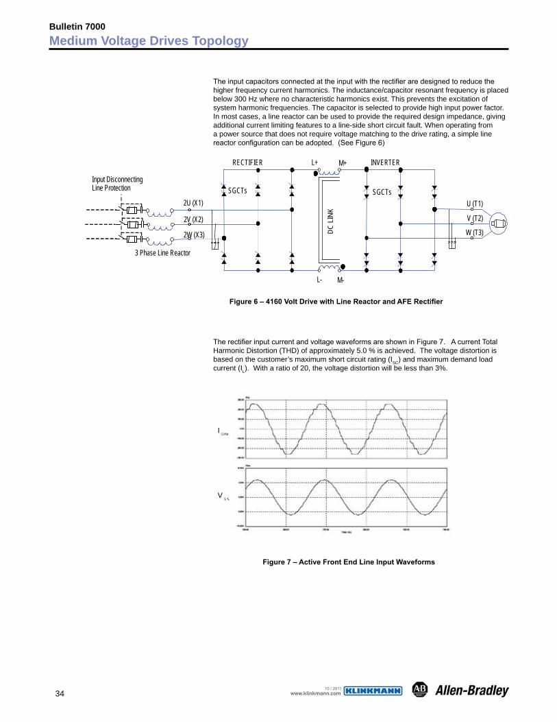
Theinputcapacitorsconnectedattheinputwiththerectifieraredesignedtoreducethehigherfrequencycurrentharmonics.Theinductance/capacitorresonantfrequencyisplacedbelow300Hzwherenocharacteristicharmonicsexist.Thispreventstheexcitationofsystemharmonicfrequencies.Thecapacitorisselectedtoprovidehighinputpowerfactor.Inmostcases,alinereactorcanbeusedtoprovidetherequireddesignimpedance,givingadditionalcurrentlimitingfeaturestoaline-sideshortcircuitfault.Whenoperatingfromapowersourcethatdoesnotrequirevoltagematchingtothedriverating,asimplelinereactorconfigurationcanbeadopted.(SeeFigure6)
2U (X1)
2V (X2)
2W (X3)
3 Phase Line Reactor
Input DisconnectingLine Protection
RECTIFIER
L- M-
DC L
INK
L+ M+ INVERTER
U (T1)
V (T2)
W (T3)
SGCTs SGCTs
Figure 6 – 4160 Volt Drive with Line Reactor and AFE Rectifier
TherectifierinputcurrentandvoltagewaveformsareshowninFigure7.AcurrentTotalHarmonicDistortion(THD)ofapproximately5.0%isachieved.Thevoltagedistortionisbasedonthecustomer’smaximumshortcircuitrating(ISC)andmaximumdemandloadcurrent(IL).Witharatioof20,thevoltagedistortionwillbelessthan3%.
I Line
V L-L
Figure 7 – Active Front End Line Input Waveforms
Bulletin 7000Medium Voltage Drives Topology
www.klinkmann.com10 / 2011
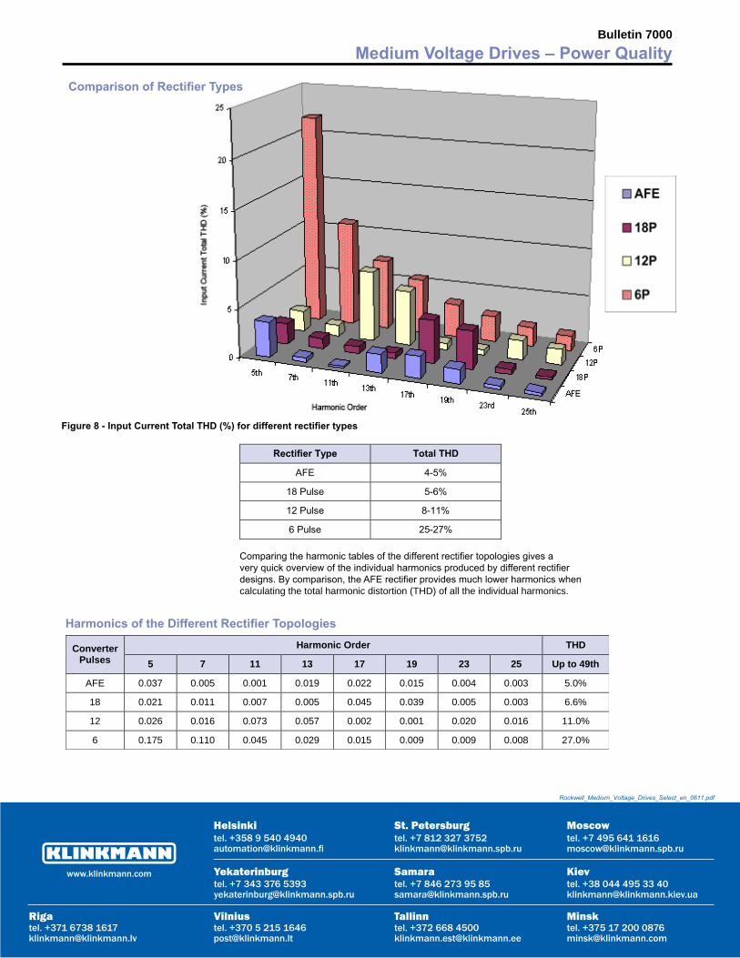
Figure 8 - Input Current Total THD (%) for different rectifier types
Comparingtheharmonictablesofthedifferentrectifiertopologiesgivesaveryquickoverviewoftheindividualharmonicsproducedbydifferentrectifierdesigns.Bycomparison,theAFErectifierprovidesmuchlowerharmonicswhencalculatingthetotalharmonicdistortion(THD)ofalltheindividualharmonics.
Harmonics of the Different Rectifier TopologiesHarmonic Order THD Converter
Pulses 5 7 11 13 17 19 23 25 Up to 49th
AFE 0.037 0.005 0.001 0.019 0.022 0.015 0.004 0.003 5.0%
18 0.021 0.011 0.007 0.005 0.045 0.039 0.005 0.003 6.6%
12 0.026 0.016 0.073 0.057 0.002 0.001 0.020 0.016 11.0%
6 0.175 0.110 0.045 0.029 0.015 0.009 0.009 0.008 27.0%
Bulletin 7000Medium Voltage Drives – Power Quality
Comparison of Rectifier Types
Yekaterinburgtel. +7 343 376 [email protected]
St. Petersburgtel. +7 812 327 [email protected]
Moscowtel. +7 495 641 [email protected]
Кievtel. +38 044 495 33 [email protected]
Helsinkitel. +358 9 540 [email protected]
Vilniustel. +370 5 215 [email protected]
Rigatel. +371 6738 [email protected]
Мinsktel. +375 17 200 [email protected]
Tallinntel. +372 668 [email protected]
Samaratel. +7 846 273 95 [email protected]
www.klinkmann.com
Rockwell_Medium_Voltage_Drives_Select_en_0611.pdf