medusa 4.034 software manual - fluidx.biofluidx.bio/manuals/xtr-1dm.pdf · xtr-1 datamouse™ pro...
TRANSCRIPT

XTR-1 DataMouse™ Pro
2D Hand Held Reader
and
Medusa 4.034 Software™
Manual
Rel. 1.0 November 2009
1
Index
Index ......................................................................................................................... 1
Welcome ................................................................................................................... 2
System Requirements ............................................................................................. 3
Installing the Software............................................................................................. 4
Main Screen.............................................................................................................. 9
The Menu Bar...................................................................................................... 12
Snapshot Settings.............................................................................................. 13
Image Enhancement .......................................................................................... 15
Sequence Mode...................................................................................................... 16
Sequence Event Controls .................................................................................. 18
On Initialise Menu............................................................................................... 18
Script Menu......................................................................................................... 19
On Trigger Menu................................................................................................. 19
On Read Menu .................................................................................................... 20
Optional 2x16 character Display Unit output ................................................... 22
System Variables................................................................................................ 23
Database ............................................................................................................. 24
File ....................................................................................................................... 24
Script ................................................................................................................... 25
Keyboard Wedge ................................................................................................ 25
Script ................................................................................................................... 26
On No Read Menu .............................................................................................. 26
System Variables................................................................................................ 28
Script ................................................................................................................... 29
Sequence Execution .......................................................................................... 29
Appendix A ActiveX Control Documentation ..................................................... 31
EPMedusa Object ............................................................................................... 31
Appendix B Advanced Decode Settings........................................................... 39
Appendix C Visual Basic Script Example ......................................................... 40
Appendix D Description of the Data Matrix code............................................. 44
Appendix E Examples of DataMouse Part Set-Ups........................................... 45
Appendix F DataMouse Driver Installation ........................................................ 47

2
Welcome
The Absolute Vision DataMouse™ Pro Reader is the latest member of a family of sophisticated
2D Data Matrix code readers capable of reading marks directly applied to a wide range of surfaces
including polished metals and plastics using marking methods such as ink jet, laser, impact marking
and chemical etching. The software has been designed to run with the minimum of user input and
set-up.
In many ways the DataMouse™ is used like a conventional computer mouse with a real time image
continuously displayed on the screen and the Operator only has to move the mouse until the target
Data Matrix code falls within the field of view.
In normal operation the software can be configured to continuously read, or to wait for a button press
or an external trigger command. Upon receiving this command it the DataMouse™ immediately
attempts to decode any 2D code that can be found within the Field of View (FOV). After decoding, the
software will then produce an output according to whether a code was successfully found and various
configurable output options. These outputs can include audible beeps and the transmission of
successful codes to other applications plus the display of the data on the screen.
In addition to the real time image display another unique feature is the ability of the DataMouse™ to
“learn” the optimum lighting and decoding settings for a particular Directly Marked Data Matrix code.
This greatly simplifies the Operator’s task when a new marked component presents itself. The
DataMouse only has to be placed over the new mark and the button pressed, moments later the
optimum settings have been determined and the reader is happily reading away. It really is as simple
as that. For more details see the Quick Start Guide in the later section of this manual.
.

3
System Requirements
• Windows 2000 or XP
• Intel Pentium II 450Mhz or better
• Minimum 256MB RAM
• One USB 1.1 data port,
• CD-ROM Drive
• Absolute Vision DataMouse™ Pro Reader

4
Installing the Software
Caution: AS WITH ALL USB DEVICE INSTALLATIONS, DO NOT PLUG THE DATAMOUSE IN
UNTIL AFTER THE SOFTWARE HAS BEEN INSTALLED Insert the Install Medusa™ CD into the CD-ROM drive. After a few moments the familiar Windows Installation Wizard menu screen is displayed. If the Wizard does not appear automatically click on the Windows Start menu and select Run. Browse for the CD drive and click on the Set-up icon (usually at D:\setup.exe). The ‘Install Wizard’ menu will be displayed, Click Next > to continue with the installation and follow the instructions.
After rebooting the system you should now plug your DataMouse reader into a vacant USB port and await the audible and screen messages acknowledging that the USB device drivers have automatically installed as is common with all USB devices.
Once the DataMouse drivers have automatically installed you can start the DataMouse application by double clicking the Absolute Vision Medusa 4.0 icon which has appeared on the Desk Top:
Now continue with the Getting Started Guide in the next Section.

5
Getting Started Guide Start the DataMouse application by double clicking the Absolute Vision Medusa 4.0 icon which has been automatically placed on the Desk Top:
This will be followed by the display indicating that Medusa is initialising:
If the following message appears check that the DataMouse reader has been plugged in and the USB drivers have been installed.
Occasionally the DataMouse drivers fail to automatically install and on these rare occasions please follow the procedure described in Appendix F:
6
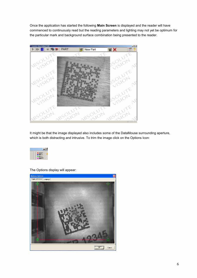
Once the application has started the following Main Screen is displayed and the reader will have
commenced to continuously read but the reading parameters and lighting may not yet be optimum for
the particular mark and background surface combination being presented to the reader.
It might be that the image displayed also includes some of the DataMouse surrounding aperture,
which is both distracting and intrusive. To trim the image click on the Options Icon:
The Options display will appear:

7
To trim the image move the four region of interest ROI handles to align with the opening in the Mouse
while excluding the surrounding lighting arrays. Once this is achieved click on the OK button and the
optimum image will be displayed:
Now simply press the button on the DataMouse while it is in position over the mark to be read. The
indicator lights will turn Orange while the reader enters the Training Mode. When the Training
operation is completed the reader will have successfully read the code, a beep will be sounded from
the PC, the LED indicators will flash green, a red box will be displayed around the image of the code
and the data contained in the Matrix will be displayed in a green box below the image.

8
You are now successfully reading a directly applied Data Matrix code and all that is required is to
place the reader over a similar code for it to be read immediately. By ‘similar’ we mean a mark of the
same size in terms of the number of rows and columns of cells but not necessarily the same data
content.
If you wish to read a mark of a different size, or one marked using a different technology, or on a
different surface finish then press the button to re-train the reader for the new mark type.
For more details on customising the reading process please refer to the next section – Main Screen.

9
Main Screen
The DataMouse™ Reader main screen includes a menu and button bar, a camera live video output
window and a status bar.
Main Screen Display
The reader is now ready to train and read a Data Matrix code.
The DataMouse has a single central button, holding the reader over a code and pressing this button
will momentarily put the reader into the Training Mode. In this mode the two indicator LEDs will glow
yellow. When the Training operation is completed the reader will have successfully read the code, the
PC will sound a beep, the LED indicators will flash green, a red box will be displayed around the
image of the code and the data read will be displayed in a green box below the image.

10
Screen Display following a Successful Training operation
Set-up Mode
The Main Screen Display has three active areas: the Menu Bar at the top of the screen plus two
hidden menus one to either side of the central live video image. To reveal these menus move the
mouse to the active areas and the menus will be displayed. Moving to the Right shows the Snapshot
and Decode settings, moving to the Left reveals the Part Management menus:
Right Hand: Picture and Decode Settings Menus

11
Picture Snapshot Menu Matrix Decode Settings

12
The Menu Bar
The menu bar includes a number of context sensitive commands for faster operation.
From left to right the function of these Menu Bar buttons are:
Run Once, Run Continuously and Stop Reading.
Single Part reading, Select Sequence mode and Run Sequence Reading buttons.
13
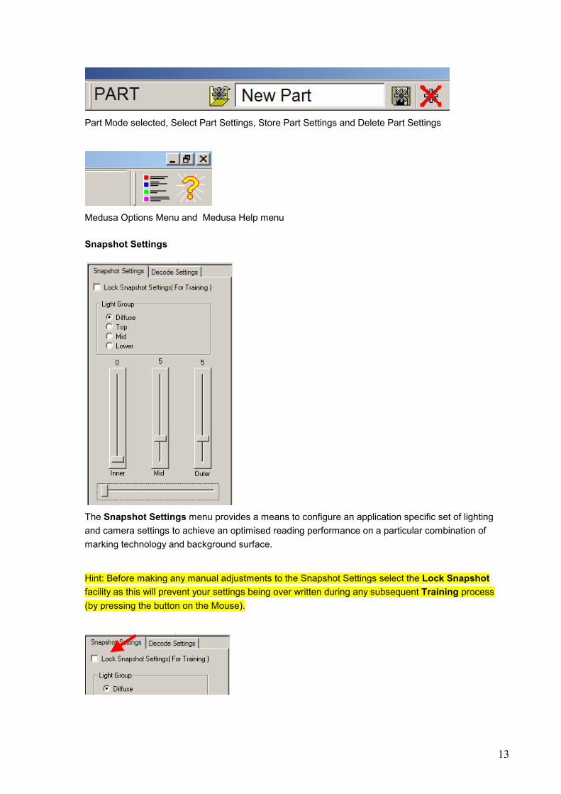
Part Mode selected, Select Part Settings, Store Part Settings and Delete Part Settings
Medusa Options Menu and Medusa Help menu
Snapshot Settings
The Snapshot Settings menu provides a means to configure an application specific set of lighting
and camera settings to achieve an optimised reading performance on a particular combination of
marking technology and background surface.
Hint: Before making any manual adjustments to the Snapshot Settings select the Lock Snapshot
facility as this will prevent your settings being over written during any subsequent Training process
(by pressing the button on the Mouse).
14
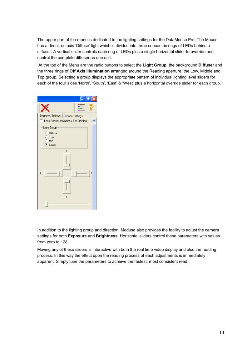
The upper part of the menu is dedicated to the lighting settings for the DataMouse Pro. The Mouse
has a direct, on axis ‘Diffuse’ light which is divided into three concentric rings of LEDs behind a
diffuser. A vertical slider controls each ring of LEDs plus a single horizontal slider to override and
control the complete diffuser as one unit.
At the top of the Menu are the radio buttons to select the Light Group, the background Diffuser and
the three rings of Off Axis illumination arranged around the Reading aperture, the Low, Middle and
Top group. Selecting a group displays the appropriate pattern of individual lighting level sliders for
each of the four sides ‘North’, ‘South’, ‘East’ & ‘West’ plus a horizontal override slider for each group.
In addition to the lighting group and direction, Medusa also provides the facility to adjust the camera
settings for both Exposure and Brightness. Horizontal sliders control these parameters with values
from zero to 128
Moving any of these sliders is interactive with both the real time video display and also the reading
process. In this way the effect upon the reading process of each adjustments is immediately
apparent. Simply tune the parameters to achieve the fastest, most consistent read.
15
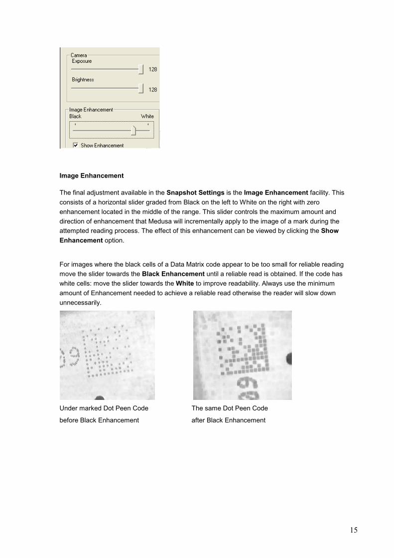
Image Enhancement
The final adjustment available in the Snapshot Settings is the Image Enhancement facility. This
consists of a horizontal slider graded from Black on the left to White on the right with zero
enhancement located in the middle of the range. This slider controls the maximum amount and
direction of enhancement that Medusa will incrementally apply to the image of a mark during the
attempted reading process. The effect of this enhancement can be viewed by clicking the Show
Enhancement option.
For images where the black cells of a Data Matrix code appear to be too small for reliable reading
move the slider towards the Black Enhancement until a reliable read is obtained. If the code has
white cells: move the slider towards the White to improve readability. Always use the minimum
amount of Enhancement needed to achieve a reliable read otherwise the reader will slow down
unnecessarily.
Under marked Dot Peen Code The same Dot Peen Code
before Black Enhancement after Black Enhancement
16
Sequence Mode
The DataMouse™ Reader main screen includes a menu button to select the Sequence Mode of
operation. This mode links a number of Part types to create a versatile reading regime in which you
can control both the reading and lighting settings to cover an optimised range suitable for your
particular components. It also allows expansion of the reader’s functionality by using Sequence
Event controls – see later in this section.
First of all create a number individual Part Files as described in the Main Screen section. Each file
contains the relevant reading and lighting settings and should be saved as a Part with a meaningful
title. See the Main Screen section for details.
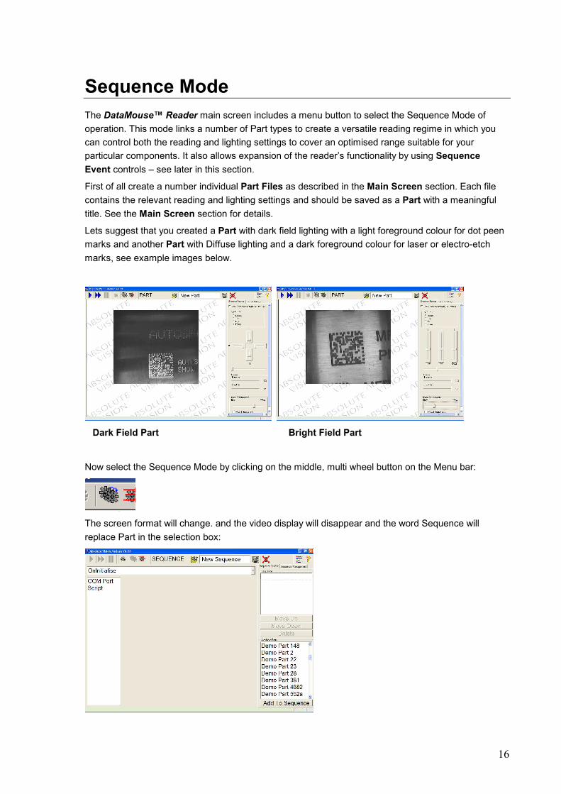
Lets suggest that you created a Part with dark field lighting with a light foreground colour for dot peen
marks and another Part with Diffuse lighting and a dark foreground colour for laser or electro-etch
marks, see example images below.
Dark Field Part Bright Field Part
Now select the Sequence Mode by clicking on the middle, multi wheel button on the Menu bar:
The screen format will change. and the video display will disappear and the word Sequence will
replace Part in the selection box:

17
The Sequence display consists of two areas, the Sequence Builder and Manager on the right hand
side of the display and the Event Manager on the top and left hand side. Moving the mouse pointer
to the right of the screen reveals the Sequence Builder menu
The Available Parts section at the bottom of the display list all the individual Parts that are currently stored on the system. To build a sequence, click on the required part to highlight it then click on the Add to Sequence button. The selected Part will then appear in the upper Sequence window as well. Repeat this process to compile a sequence of all the parts the the reader will be required to read on this assignment. Hint Do remember that each individual Part can be as ‘Open’ ie versatile, or ‘Closed’ i.e. specific as you wish. Remember also that Closed Parts will deliver a more robust read of indistinct or distorted marks than Open part settings. If your marks are on a rough background or have low contrast try using a number of different Closed Parts in preference to just one Open Part to achieve a more consistent result. Once a sequence has been defined, as shown opposite, it can be saved by selecting the Sequence Management tab.
To save a sequence for use at a later time first you must give it a title by typing into the Name window. In the example on the left we have called it ‘Test Sequence’. Then click on the Save Sequence button below the window. From the Sequence Management menu you can Load any saved sequence and make it active. You can also Delete any sequence which is no longer required. New Sequence clears the existing sequence setting and lets you define a new sequence from scratch.

18
Sequence Event Controls
Once a Sequence has been defined, decisions must be made concerning how a sequence is to be
initiated and what other controls and outputs are to take place while a Ssequence is being executed.
Clicking on the Event pull down menu lists the four categories of Event supported by Medusa:
Trigger – occurs when the reading of a Data matrix code is instigated.
On Initialise – occurs when the DataMouse Medusa software is started.
On Read – occurs when a successful read of a Data Matrix code takes place.
On No Read – occurs when a read of a data matrix code is attempted but is unsuccessful.
You can define the actions to take place during each Event by first highlighting particular event
within the pull down menu and then selecting from the context driven menu that appears. We will
describe each in turn.
On Initialise Menu
Clicking on the On Initialise event gives two choices, selecting and defining the COM Port settings to
transfer the read data to an external device via RS 232 serial communications and selecting a Visual
Basic Script to execute at this time.
19
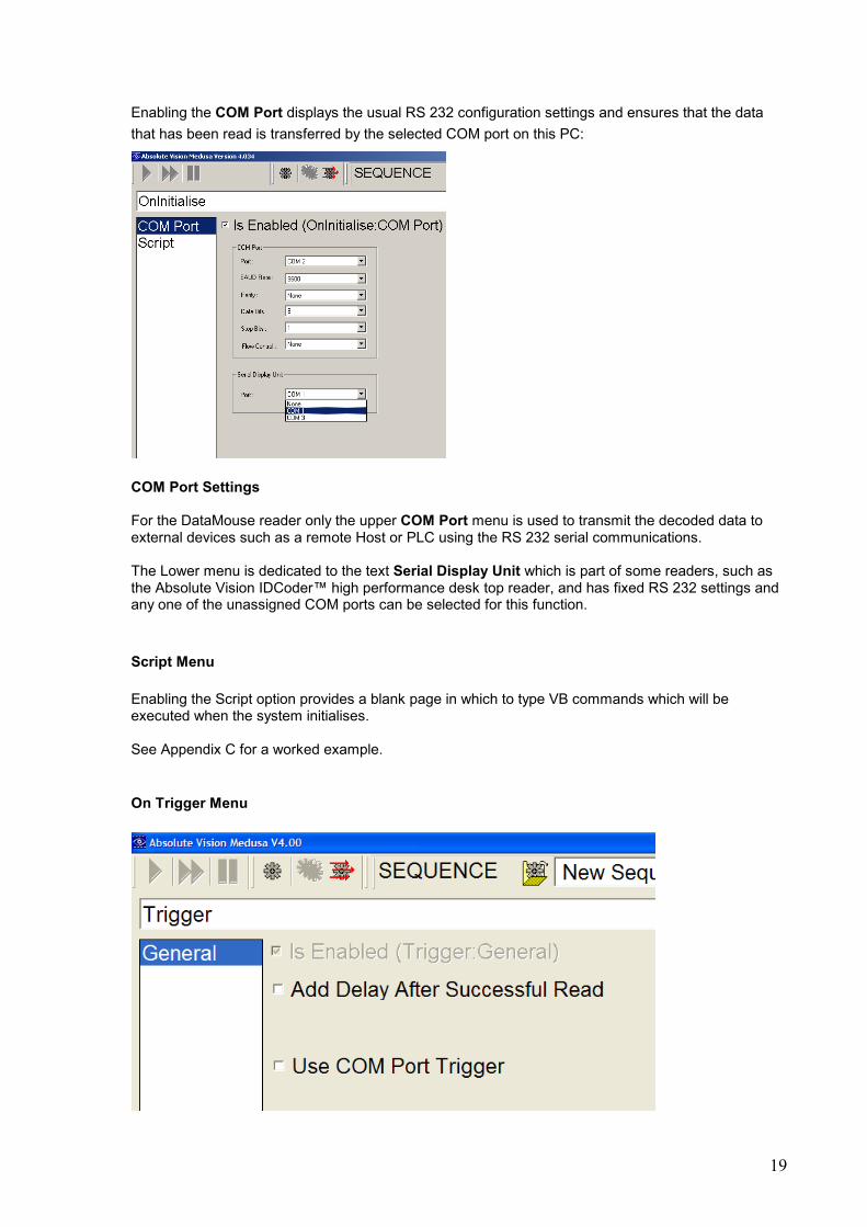
Enabling the COM Port displays the usual RS 232 configuration settings and ensures that the data
that has been read is transferred by the selected COM port on this PC:
COM Port Settings For the DataMouse reader only the upper COM Port menu is used to transmit the decoded data to external devices such as a remote Host or PLC using the RS 232 serial communications. The Lower menu is dedicated to the text Serial Display Unit which is part of some readers, such as the Absolute Vision IDCoder™ high performance desk top reader, and has fixed RS 232 settings and any one of the unassigned COM ports can be selected for this function.
Script Menu
Enabling the Script option provides a blank page in which to type VB commands which will be executed when the system initialises. See Appendix C for a worked example.
On Trigger Menu

20
The Trigger event provides two choices: to impose a delay of a selected duration after every successful read and the option to Trigger reads via the RS 232 COM port as previously defined in the Initialise event. The Delay has a default value of 2000 msec (2 seconds) and this is used to avoid multiple reads of the same code and hence duplicate data being transmitted to the system Host, either by the COM port or via the direct Software Wedge facility to other Windows applications on the same PC. The value of this delay can be altered simply by highlighting it and typing the new value into the menu:
Selecting the COM Port Trigger displays a vacant window into which you can type the text string that the Host will use to trigger the reading of a code, for example when the Host is aware that a new part is in the Reader’s field of view. An example of a suitable trigger text string would be “READNOW”
On Read Menu
This event provides the most choices.

21
The Beep option provides the means to enable the PCs speaker to register a successful read. The volume of this Beep is controlled from the standard Windows speaker setting on the Task Bar:
The COM port option provides the means to manipulate the data sent to the Host via the RS 232 port when a successful read occurs:
The message can be a composed of System Variables which are defined within square brackets [ ] and fixed text. For example the Variable [READCODE] contains the exact data read from the Data Matrix 2D bar code and is obviously a common part of most On Read messages. In a multiple reader system it is also common to place a reader identifier before or after the [READCODE] field and it might be useful to include the time e.g.: “DM1- [READCODE]-[HOUR]:[MINUTE]:[SECOND]”

22
In this way the HOST is in no doubt as to the source of the data it has just received and this is achieved by typing the fixed text within inverted commas “ ” into the Output Modifier window:
The line below the Text entry window displays the actual data that would be sent to the Host with the [READCODE] data substituted for the test text “Testing 123456”. To further test the integrity of the set up you have defined you can force the transmission of this test message by clicking on the Test Transmit button in the lower right hand corner of this menu.
Optional 2x16 character Display Unit output
In the first example the display output modifier requires the text to be ‘wrapped’ in the display: when the text is longer than 16 characters the code will be broken by an ellipsis (…) over the two lines of the display. If the code is longer than 26 characters the first 13 will be shown on the first line and the last 13 on the second line. In the second example two lines of output may be specified. When a line of information is longer than 16 characters the leftmost 13 characters plus an ellipsis are displayed on the first line and an ellipsis followed by the rightmost 13 characters are displayed on the second line.
23
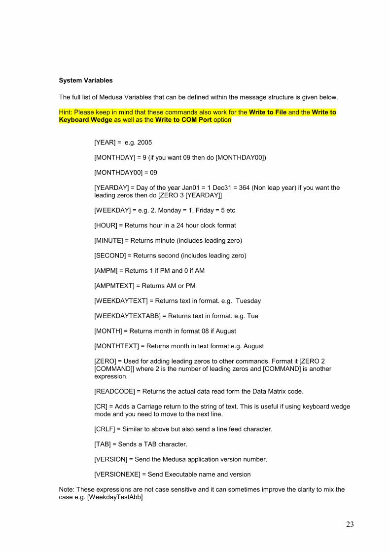
System Variables
The full list of Medusa Variables that can be defined within the message structure is given below. Hint: Please keep in mind that these commands also work for the Write to File and the Write to Keyboard Wedge as well as the Write to COM Port option
[YEAR] = e.g. 2005 [MONTHDAY] = 9 (if you want 09 then do [MONTHDAY00]) [MONTHDAY00] = 09 [YEARDAY] = Day of the year Jan01 = 1 Dec31 = 364 (Non leap year) if you want the leading zeros then do [ZERO 3 [YEARDAY]] [WEEKDAY] = e.g. 2. Monday = 1, Friday = 5 etc [HOUR] = Returns hour in a 24 hour clock format [MINUTE] = Returns minute (includes leading zero) [SECOND] = Returns second (includes leading zero) [AMPM] = Returns 1 if PM and 0 if AM [AMPMTEXT] = Returns AM or PM [WEEKDAYTEXT] = Returns text in format. e.g. Tuesday [WEEKDAYTEXTABB] = Returns text in format. e.g. Tue [MONTH] = Returns month in format 08 if August [MONTHTEXT] = Returns month in text format e.g. August [ZERO] = Used for adding leading zeros to other commands. Format it [ZERO 2 [COMMAND]] where 2 is the number of leading zeros and [COMMAND] is another expression. [READCODE] = Returns the actual data read form the Data Matrix code. [CR] = Adds a Carriage return to the string of text. This is useful if using keyboard wedge mode and you need to move to the next line. [CRLF] = Similar to above but also send a line feed character. [TAB] = Sends a TAB character. [VERSION] = Send the Medusa application version number. [VERSIONEXE] = Send Executable name and version
Note: These expressions are not case sensitive and it can sometimes improve the clarity to mix the case e.g. [WeekdayTestAbb]

24
Database
The On Read Database option provides the facility to port the read data directly to an SQL database located either on this PC or another networked processor. To enter the data into this database you will require both the correct Connection String text and the SQL Statement both of which can be provided by your Network Administrator. Using the Test buttons located next to each of the text entry windows can test the correct functioning of both of these elements.
File
The File option provides the means to transfer the read data, plus defined header and trailer text, to a text file (.txt) for processing by a third party application. You can select whether data can create a new file in a folder that you designate using the usual file reference string or add the read data to an existing file or fully overwrite a file.

25
Script
The Script option provides the means to define a short piece of Visual Basic code that will be executed on the On Read Event. Simply enter the code into the vacant window and then save the Sequence using your own Sequence title so that you can recall it later. For a worked example of a VB Script please refer to Appendix C
Keyboard Wedge
The Keyboard Wedge (KW) is the simplest method to transfer data from a Data Matrix to a Windows application running on the same PC. It can be used with legacy Windows applications regardless of age and without any modification to the target application software.

26
Basically KW allows the DataMouse reader to mimic keyboard entry of data into any application. With KW selected you should ensure that the target application has Focus, that is the application is on top of the Desk Top, and that the cursor is located at the beginning of the target data entry field. Now, instead of manually typing the data into the field, you place the DataMouse over the code to be read and the data will be automatically entered into the target field, quickly and without errors. As with the other data handling options Header and Trailer text can be added to the data. Hint: Do ensure that the 2.00 second delay after a Good Read is enabled to avoid repetition of the data being entered into the target field. See the On Good Read option set up.
Script
The Script option provides the means to define a short piece of Visual Basic code that will be executed on the event of a No Read. Simply enter the VB code into the vacant window and then save the Sequence using your own Sequence title so that you can recall it later.
For a worked example of a VB Script please refer to Appendix C
On No Read Menu
The choices on this menu are similar to the On Read Menu.
27
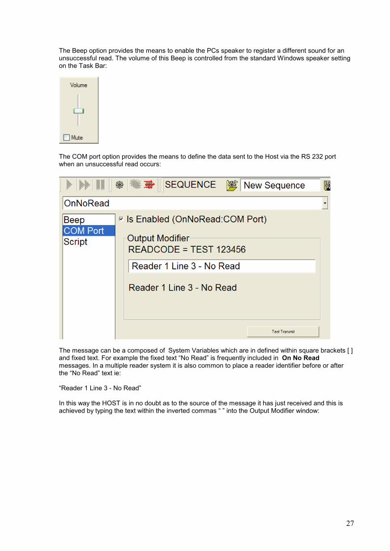
The Beep option provides the means to enable the PCs speaker to register a different sound for an unsuccessful read. The volume of this Beep is controlled from the standard Windows speaker setting on the Task Bar:
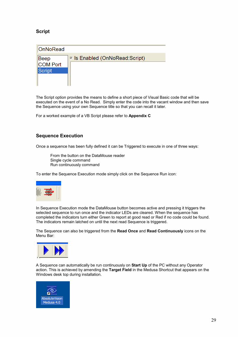
The COM port option provides the means to define the data sent to the Host via the RS 232 port when an unsuccessful read occurs:
The message can be a composed of System Variables which are in defined within square brackets [ ] and fixed text. For example the fixed text “No Read” is frequently included in On No Read messages. In a multiple reader system it is also common to place a reader identifier before or after the “No Read” text ie: “Reader 1 Line 3 - No Read” In this way the HOST is in no doubt as to the source of the message it has just received and this is achieved by typing the text within the inverted commas “ ” into the Output Modifier window:

28
System Variables
The full list of Medusa Variables that can be defined within the message structure is given below. Hint: Please keep in mind that these commands also work for the Write to File and the Write to Keyboard Wedge as well as the Write to Com Port option
[YEAR] = e.g. 2005 [MONTHDAY] = 9 (if you want 09 then do [MONTHDAY00]) [MONTHDAY00] = 09 [YEARDAY] = Day of the year Jan01 = 1 Dec31 = 364 (Non leap year) if you want the leading zeros then do [ZERO 3 [YEARDAY]] [WEEKDAY] = e.g. 2. Monday = 1, Friday = 5 etc [HOUR] = Returns hour in a 24 hour clock format [MINUTE] = Returns minute (includes leading zero) [SECOND] = Returns second (includes leading zero) [AMPM] = Returns 1 if PM and 0 if AM [AMPMTEXT] = Returns AM or PM [WEEKDAYTEXT] = Returns text in format. e.g. Tuesday [WEEKDAYTEXTABB] = Returns text in format. e.g. Tue [MONTH] = Returns month in format 08 if August [MONTHTEXT] = Returns month in text format e.g. August [ZERO] = Used for adding leading zeros to other commands. Format it [ZERO 2 [COMMAND]] where 2 is the number of leading zeros and [COMMAND] is another expression. [READCODE] = Returns the actual data read form the Data Matrix code. [CR] = Adds a Carriage return to the string of text. This is useful if using keyboard wedge mode and you need to move to the next line. [CRLF] = Similar to above but also send a line feed character. [TAB] = Sends a TAB character. [VERSION] = Send the Medusa application version number. [VERSIONEXE] = Send Executable name and version
Note: These expressions are not case sensitive and it can sometimes improve the clarity to mix the case e.g. [WeekdayTestAbb]
29
Script
The Script option provides the means to define a short piece of Visual Basic code that will be executed on the event of a No Read. Simply enter the code into the vacant window and then save the Sequence using your own Sequence title so that you can recall it later. For a worked example of a VB Script please refer to Appendix C
Sequence Execution
Once a sequence has been fully defined it can be Triggered to execute in one of three ways: From the button on the DataMouse reader Single cycle command Run continuously command To enter the Sequence Execution mode simply click on the Sequence Run icon:
In Sequence Execution mode the DataMouse button becomes active and pressing it triggers the selected sequence to run once and the indicator LEDs are cleared. When the sequence has completed the indicators turn either Green to report at good read or Red if no code could be found. The indicators remain latched on until the next read Sequence is triggered. The Sequence can also be triggered from the Read Once and Read Continuously icons on the Menu Bar:
A Sequence can automatically be run continuously on Start Up of the PC without any Operator action. This is achieved by amending the Target Field in the Medusa Shortcut that appears on the Windows desk top during installation.
30
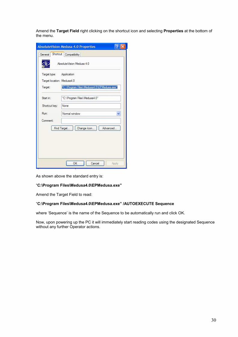
Amend the Target Field right clicking on the shortcut icon and selecting Properties at the bottom of the menu.
As shown above the standard entry is: “C:\Program Files\Medusa4.0\EPMedusa.exe” Amend the Target Field to read: “C:\Program Files\Medusa4.0\EPMedusa.exe” /AUTOEXECUTE Sequence where ‘Sequence’ is the name of the Sequence to be automatically run and click OK. Now, upon powering up the PC it will immediately start reading codes using the designated Sequence without any further Operator actions.

31
Appendix A ActiveX Control Documentation
The Medusa 4 software ActiveX control allows users to write custom DataMatrix reading applications
using programming languages such as Visual Basic.
Below is a simple demonstration application which allows different parts and sequences in Medusa to
be selected and executed for reading DataMatrix codes.
The ActiveX control exposes the following Methods and Properties for building a custom DataMatrix
reading application. A sample program developed in Visual Basic 6.0 is distributed on the Medusa 4
CD for reference.
EPMedusa Object
To use the Medusa ActiveX control you need to set a Reference to the EPMedusa object. This is
done this is done using the References menu item in the Project menu in visual basic.
Then in your project you need to Dimension the Medusa object using the code below.
Dim Medusa As New EPAXMedusa.

32
Capture Next Frame Method
Displays the current frame from the reader on the screen.
The ActiveX control does not support live streaming of the image. Instead you should refresh the
image on a timer. Typically a 100ms timer will give a sufficient 10 frames per second.
The image size relates to the configured size within the Medusa software. See the options dialog in
Medusa for details.
Syntax
Medusa.CaptureNextFrame( hwnd As Long, X as Long, Y as Long)
Hwnd – Handle to the Window to display the reader image,
X – The Horizontal screen position to display the top corner of the screen. In the example above the
X position is 0.
Y - The Vertical screen position to display the top corner of the screen. In the example above the Y
position is 0.
VB6 Example
Private Sub Timer1_Timer()
‘ Display the image a 100 x 100 on the main form
Medusa.CaptureNextFrame( Me.hWnd, 100, 100)
End Sub
ClearButtonPress Method
Clears the HasButtonBeenPressed property. When the DataMouse™ button is pressed a flag is
latched internally. This can be read using the HasButtonBeenPressed property. It is recommended
that the ClearButtonPress method is called after the HasButtonBeenPressed property been
detected to be true and processed.
VB6 Example
Private Sub Timer1_Timer()
If Medusa.HasButtonBeenPressed then
‘Do the read in the DoRead function
Call DoRead
‘ Clear the HasButtonBeenPressed property
Medusa.ClearButonPress

33
Endif
End Sub
ExecutePart Method
Executes a Pre-configured Medusa 4 part. Parts are trained and saved using the main Medusa4
software. You can then call (execute) these parts in the ActiveX control to read the DataMatrix code.
Syntax
Medusa.ExecutePart(PartName as String)
PartName – Defines the name of the part previously configured in Medusa4. This is the Part which is
loaded and executed.
The read result is the ReadCode property.
VB6 Example
Private Function DoRead() As String
Medusa.ExecutePart “TEST”
‘Wait until Medusa has finished
Do
DoEvents
Loop While Medusa.IsExecuting
‘Was read successful, if so return result
If Medusa.HasCodeRead = 0 then
DoRead = “No Read”
Else
DoRead = Medusa.ReadCode
End If
End Sub
Note pre-configured Sequences can also be executed if multiple code configurations need to be read.
See the ExecuteSequence method.
ExecuteSequence Method
Executes a Pre-configured Medusa 4 sequence. Sequences are created and saved using the main
Medusa4 software. You can then call (execute) these sequences in the ActiveX control to read the
DataMatrix code.
Syntax
Medusa.ExecuteSequence(SequenceName as String)
34
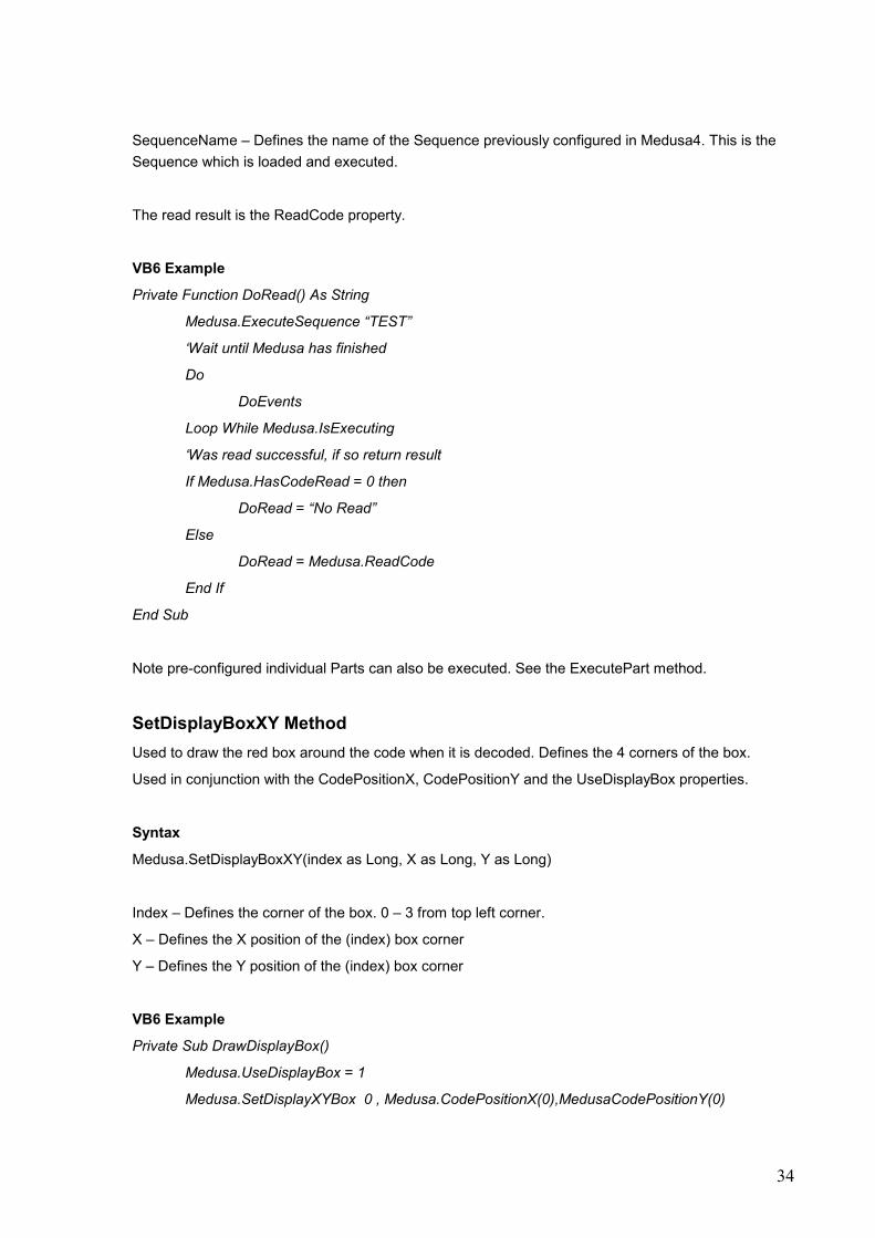
SequenceName – Defines the name of the Sequence previously configured in Medusa4. This is the
Sequence which is loaded and executed.
The read result is the ReadCode property.
VB6 Example
Private Function DoRead() As String
Medusa.ExecuteSequence “TEST”
‘Wait until Medusa has finished
Do
DoEvents
Loop While Medusa.IsExecuting
‘Was read successful, if so return result
If Medusa.HasCodeRead = 0 then
DoRead = “No Read”
Else
DoRead = Medusa.ReadCode
End If
End Sub
Note pre-configured individual Parts can also be executed. See the ExecutePart method.
SetDisplayBoxXY Method
Used to draw the red box around the code when it is decoded. Defines the 4 corners of the box.
Used in conjunction with the CodePositionX, CodePositionY and the UseDisplayBox properties.
Syntax
Medusa.SetDisplayBoxXY(index as Long, X as Long, Y as Long)
Index – Defines the corner of the box. 0 – 3 from top left corner.
X – Defines the X position of the (index) box corner
Y – Defines the Y position of the (index) box corner
VB6 Example
Private Sub DrawDisplayBox()
Medusa.UseDisplayBox = 1
Medusa.SetDisplayXYBox 0 , Medusa.CodePositionX(0),MedusaCodePositionY(0)

35
Medusa.SetDisplayXYBox 1 , Medusa.CodePositionX(1),MedusaCodePositionY(1)
Medusa.SetDisplayXYBox 2 , Medusa.CodePositionX(2),MedusaCodePositionY(2)
Medusa.SetDisplayXYBox 3 , Medusa.CodePositionX(3),MedusaCodePositionY(3)
End Sub
CodePositionX Property
After a code has been decoded this returns the horizontal coordinate of each of the 4 corners of the
code. This is useful when drawing the red box around the code. See SetDisplayBoxXY method for
more information.
Syntax
Medusa.CodePositionX (Index)
Index – Defines which of the 4 corners of the code position to return (0 – 3 range)
CodePositionY Property
After a code has been decoded this returns the vertical coordinate of each of the 4 corners of the
code. This is useful when drawing the red box around the code. See SetDisplayBoxXY method for
more information.
Syntax
Medusa.CodePositionY (Index)
Index – Defines which of the 4 corners of the code position to return (0 – 3 range)
HasButtonBeenPressed Property
Returns true if the button on the DataMouse has been pressed. It is useful to poll this on a timer to
determine when the button has been pressed to perform a decode or other operation. The property
latches when the button has been pressed and must be cleared using the ClearButonPress method.
See the ClearButonPress Method for example.
HasCodeRead Property
Returns true if the code was successfully decoded.
See the execute Part Method for usage example.
IsExecuting Property

36
Returns true if Medusa is busy executing a read. This is useful to determine when a read has
completed so the data can be read from the ReadCode property.
See the ExecutePart method for usage examples.
ReadCode Property
The ReadCode returns a string containing the decoded text from the previous decode.
For usage examples see the ExecutePart method.
PartCount Property
Returns the number of Parts configured in the Medusa4 software. This is useful when looping through
the part names.
PartName Property
Returns the pre-configured Medusa 4 PartName by index.
Syntax
Medusa.PartName(index) As String
Index – Defines position in (0 – Medusa.PartCount) array.
VB6 Example
Populates a list box with all the configured MedusaPart names.
Private Sub PopulatePartListBox
For n=0 To Medusa.PartCount
List1.AddItem Medusa.PartName(n)
Next n
End Sub
SequenceCount Property
Returns the number of Sequences configured in the Medusa4 software. This is useful when looping
through the Sequence names.
Sequence Name Property
Returns the pre-configured Medusa 4 SequenceName by index.

37
Syntax
Medusa. Sequence Name(index) As String
Index – Defines position in (0 – Medusa.SequenceCount) array.
VB6 Example
Populates a list box with all the configured Medusa SequenceNames.
Private Sub Populate SequenceListBox
For n=0 To Medusa.SequenceCount
List1.AddItem Medusa.SequenceName(n)
Next n
End Sub
UseDisplayBox Property
Activates / Deactivates the red display box around the code when it has been decoded.
See the SetDisplayBoxXY method for usage examples.
Example Program Listing
Dim Medusa As New EPAXMedusa
Private Sub NextFrame_Click()
Medusa.CaptureNextFrame Me.hWnd, 0, 0
End Sub
Private Sub Decode_Click()
'The General Sequence and General1 General2, General3 parts must be in the Medusa folder.
Medusa.ExecuteSequence "General"
Do
DoEvents
Loop While Medusa.IsExecuting
Medusa.UseDisplayBox = 1
Medusa.SetDisplayBoxXY 0, Medusa.CodePositionX(0), Medusa.CodePositionY(0)
Medusa.SetDisplayBoxXY 1, Medusa.CodePositionX(1), Medusa.CodePositionY(1)
Medusa.SetDisplayBoxXY 2, Medusa.CodePositionX(2), Medusa.CodePositionY(2)
Medusa.SetDisplayBoxXY 3, Medusa.CodePositionX(3), Medusa.CodePositionY(3)
lblRead.Caption = Medusa.ReadCode
If Medusa.HasCodeRead = 0 Then
Medusa.UseDisplayBox = 0
End If
End Sub
38
Private Sub Form_Load()
'Show all parts and sequences which have been created using the Medusa 4 software.
'This is for information only.
'Parts and Sequences cannot be created by the ActiveX control these must first be created in Medusa4 then
'used by the activex control.
'For a general reader use the 3 parts General1, General2, General3 which are linked into the sequence General.
'Then run the General Sequence. This decode most codes presented to the reader.
On Error GoTo ErrHandler
App.OleRequestPendingTimeout = 100
App.OleServerBusyTimeout = 100
For n = 0 To Medusa.PartCount
List1.AddItem Medusa.PartName(n)
Next n
For n = 0 To Medusa.SequenceCount
List2.AddItem Medusa.SequenceName(n)
Next n
App.OleRequestPendingTimeout = 5000
App.OleServerBusyTimeout = 10000
Exit Sub
ErrHandler:
'No DataMouse Present
If Err.Number = 429 Then
MsgBox "The DataMouse was not detected. Application will close.", vbOKOnly, "Medusa Demo"
Set Medusa = Nothing
End
Else
MsgBox "Medusa4Demo Error : " & Err.Number & ". " & Err.Description, vbOKOnly, "Medusa Demo"
End
End If
End Sub
Private Sub Timer1_Timer()
Medusa.CaptureNextFrame Me.hWnd, 0, 0
If Medusa.HasButtonBeenPressed Then
Command2_Click
Medusa.ClearButonPress
End If
End Sub

39
Appendix B Advanced Decode Settings
This Section is being prepared.
40
Appendix C Visual Basic Script Example
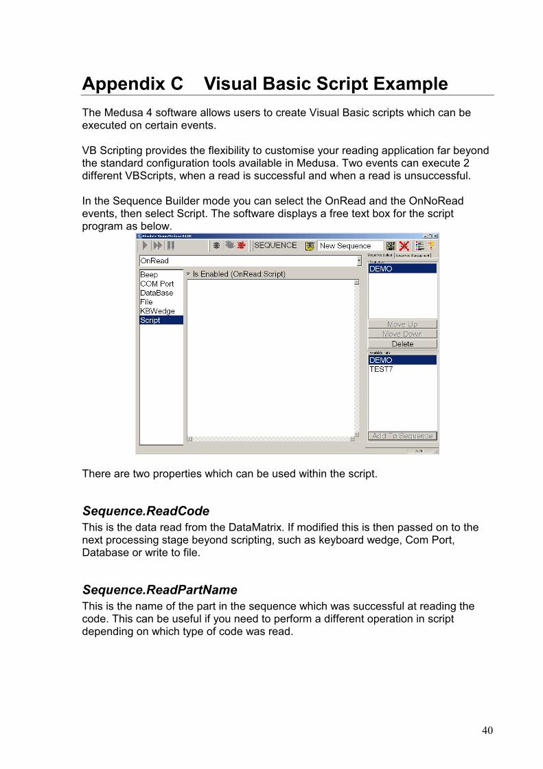
The Medusa 4 software allows users to create Visual Basic scripts which can be executed on certain events. VB Scripting provides the flexibility to customise your reading application far beyond the standard configuration tools available in Medusa. Two events can execute 2 different VBScripts, when a read is successful and when a read is unsuccessful. In the Sequence Builder mode you can select the OnRead and the OnNoRead events, then select Script. The software displays a free text box for the script program as below.
There are two properties which can be used within the script.
Sequence.ReadCode
This is the data read from the DataMatrix. If modified this is then passed on to the next processing stage beyond scripting, such as keyboard wedge, Com Port, Database or write to file.
Sequence.ReadPartName
This is the name of the part in the sequence which was successful at reading the code. This can be useful if you need to perform a different operation in script depending on which type of code was read.

41
Example
The example shows a typical requirement to convert the data from within the DataMatrix code to a format more acceptable to the receiving application which uses the Keyboard Wedge interface. The DataMatrix code to be read has been encoded to the MIL130 standard with Text element identifiers. As below.
[)>RSDD
GSMFR 12345G
SSER 123456789RSEOT
The receiving application is a simple database form which requires the MFR and SER details to be entered into 2 separate edit boxes. We can use the Keyboard Wedge feature to get the data into the Database form but the Data format will be wrong as shown in the Database form screenshot below.
Before Script
The example script below takes the decoded text and modifies it to strip out the header, footer and separator text. It also inserts carriage return and line feed characters to move the cursor from the MFR edit box to the SER edit box when the data is transmitted to the database form. Any line with the (‘) character at the start is treated as a comment. These lines are not processed by the VBScript engine. When a code is read by the Medusa software the result is stored in the Sequence.ReadCode variable. This can be used in the script and modified. The modified Sequence.ReadCode is then displayed on the main Medusa screen during the decode and is used by the Keyboard Wedge, Com Port or Data Base features.

42
The example script above initially takes a local copy of the Sequence.ReadCode and stores it to strReadCode. It then uses the Instr method to search for the position of the text MFR in the decoded data. The position of this is copied to the startpos variable. There is then an ‘if’ check to make sure that MFR does exist in the decoded data. If it does not then a message box is displayed on the screen warning the user that the code does not contain the MFR. If the MFR does exist the Instr method is used again to find the GS character which follows the MFR details (the GS character is written in VBScript as chr(29)). The startpos variable is used in the
Instr method as the starting position for the search. This is to prevent the earlier GS
character from being found. [)>R
SDDGSMFR 12345G
SSER 123456789RSEOT
startpos = 8 endpos = 17 The Mid method is used to split out the MFR data from the strReadCode variable. The Mid method requires the variable to be modified, the start position of the required text and the length to be copied. Subtracting the start pos from the endpos gives the length of the MFR data. The MFR data then gets copied to the strMFR variable. Mid(“[)>R
SDDGSMFR 12345G
SSER 123456789RSEOT”, 8, 9) = MFR 12345
Exactly the same approach is used to strip out the SER data. This time the end character is the RS character which is written as chr(30) in VBScript. Once the strMFR and strSER are stripped out they can be combined with the carriage return and linefeed characters chr(13) and chr(10) respectively and stored
strReadCode = Sequence.ReadCode
'strip out the the MFR startpos = InStr(1, strReadCode, "MFR", vbTextCompare)
If startpos <> 0 Then
endpos = InStr(startpos, strReadCode, Chr(29), vbTextCompare) strMFR = Mid(strReadCode, startpos, endpos - startpos)
Else
MsgBox "The code does not contain the MFR details" strMFR = ""
End If
'strip out the SER
startpos = InStr(1, strReadCode, "SER", vbTextCompare) If startpos <> 0 Then
endpos = InStr(startpos, strReadCode, Chr(30), vbTextCompare)
strSER = Mid(strReadCode, startpos, endpos - startpos) Else
MsgBox "The code does not contain the SER details"
strSER = "" End If
'Now combine the two together with a carriage return / line feed 'between them so they can be sent to another application using the
'keyboard wedge Sequence.ReadCode = strMFR & chr(13)& chr(10) & strSER & chr(13) & chr(10)

43
back to the Sequence.Readcode. Which is then transmitted out of the keyboard wedge if it is configured in the KBWedge configuration screen. The result is the MFR is transmitted to the cursor in the DataBase Entry Form then an ENTER key is simulated to move the cursor to the SER entry, then the SER is transmitted, followed by another ENTER which moves the focus to the Process button.
After Script

44
Appendix D Description of the Data Matrix code
This Section is being prepared.

45
Appendix E Examples of DataMouse Part Set-Ups
This Section is being prepared

46

47
Appendix F DataMouse Driver Installation
Occasionally the DataMouse drivers fail to automatically install and on these rare occasions please follow the following procedure. On plugging the DataMouse into the USB port the following message is displayed:
Select "No, not this time" and press "Next"
Select "Install the software automatically (Recommended)" and press "Next"
48
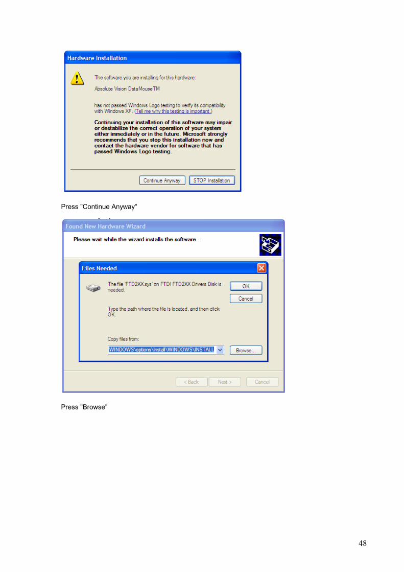
Press "Continue Anyway"
Press "Browse"
49
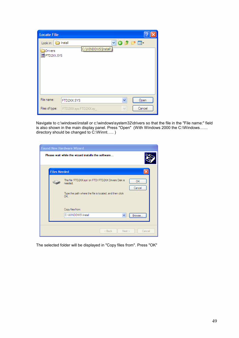
Navigate to c:\windows\install or c:\windows\system32\drivers so that the file in the "File name:" field is also shown in the main display panel. Press "Open" (With Windows 2000 the C:\Windows…… directory should be changed to C:\Winnt….. )
The selected folder will be displayed in "Copy files from". Press "OK"

50
Press "Finish"
Click the appropriate answer.
Sometimes the "Found new hardware Wizard" chases the PB 100W camera and ends up with this screen. Don't worry about it, but press "Finish"

51
This balloon will be displayed above the Windows XP task bar to show that that the DataMouse software has all be installed and you are ready to run Medusa 4.
You will now be able to run Medusa 4 by double clicking the icon on the desktop.