mega3™ medical gas notification system · mega3™ medical gas notification system specification...
TRANSCRIPT
SSB-835-014107 9510 52.04
Page 1 of 623 August 2016
BeaconMedæs • 1800 Overview Drive, Rock Hill, SC 29730 • Phone: (803) 817-5600 • Fax: (803) 817-5750 • www.beaconmedaes.com
MEGA3™ Medical Gas Notification System
SPECIFICATION
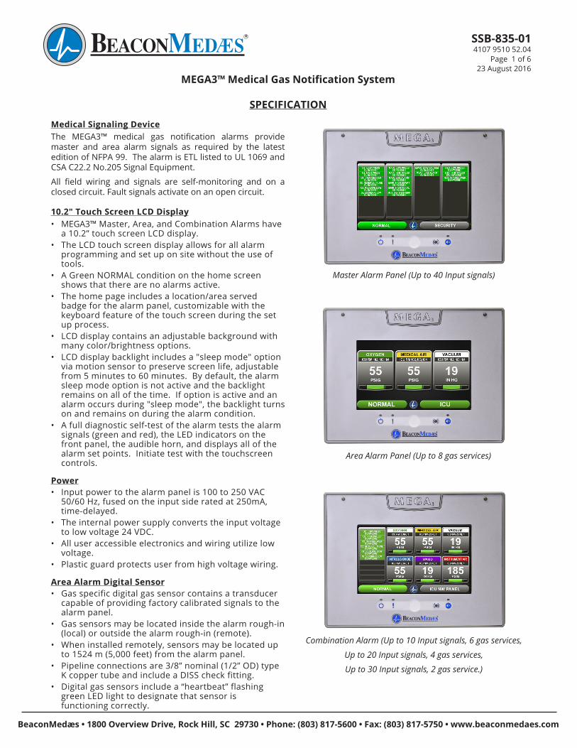
Medical Signaling DeviceThe MEGA3™ medical gas notification alarms provide master and area alarm signals as required by the latest edition of NFPA 99. The alarm is ETL listed to UL 1069 and CSA C22.2 No.205 Signal Equipment.
All field wiring and signals are self-monitoring and on a closed circuit. Fault signals activate on an open circuit.
10.2" Touch Screen LCD Display• MEGA3™ Master, Area, and Combination Alarms have
a 10.2” touch screen LCD display. • The LCD touch screen display allows for all alarm
programming and set up on site without the use of tools.
• A Green NORMAL condition on the home screen shows that there are no alarms active.
• The home page includes a location/area served badge for the alarm panel, customizable with the keyboard feature of the touch screen during the set up process.
• LCD display contains an adjustable background with many color/brightness options.
• LCD display backlight includes a "sleep mode" option via motion sensor to preserve screen life, adjustable from 5 minutes to 60 minutes. By default, the alarm sleep mode option is not active and the backlight remains on all of the time. If option is active and an alarm occurs during "sleep mode", the backlight turns on and remains on during the alarm condition.
• A full diagnostic self-test of the alarm tests the alarm signals (green and red), the LED indicators on the front panel, the audible horn, and displays all of the alarm set points. Initiate test with the touchscreen controls.
Power• Input power to the alarm panel is 100 to 250 VAC
50/60 Hz, fused on the input side rated at 250mA, time-delayed.
• The internal power supply converts the input voltage to low voltage 24 VDC.
• All user accessible electronics and wiring utilize low voltage.
• Plastic guard protects user from high voltage wiring.
Area Alarm Digital Sensor• Gas specific digital gas sensor contains a transducer
capable of providing factory calibrated signals to the alarm panel.
• Gas sensors may be located inside the alarm rough-in (local) or outside the alarm rough-in (remote).
• When installed remotely, sensors may be located up to 1524 m (5,000 feet) from the alarm panel.
• Pipeline connections are 3/8” nominal (1/2” OD) type K copper tube and include a DISS check fitting.
• Digital gas sensors include a “heartbeat” flashing green LED light to designate that sensor is functioning correctly.
Area Alarm Panel (Up to 8 gas services)
Combination Alarm (Up to 10 Input signals, 6 gas services,
Up to 20 Input signals, 4 gas services,
Up to 30 Input signals, 2 gas service.)
Master Alarm Panel (Up to 40 Input signals)
SSB-835-014107 9510 52.04
Page 2 of 623 August 2016
BeaconMedæs • 1800 Overview Drive, Rock Hill, SC 29730 • Phone: (803) 817-5600 • Fax: (803) 817-5750 • www.beaconmedaes.com BeaconMedæs • 1800 Overview Drive, Rock Hill, SC 29730 • Phone: (803) 817-5600 • Fax: (803) 817-5750 • www.beaconmedaes.com
Area Alarm Panel Configuration• Area alarm panel monitors 1 to 8 digital gas sensor
modules, installed locally or remotely.• Display screen continuously displays the monitored
gas pressures or vacuum in the piping system.• Customize gas badges on the display for gas types,
color, and language. Type in areas served per gas during set up process through the touchscreen interface.
• Program the units of measure for each gas badge to read PSI, BAR, and kPa in increments of 1 PSI, .1 BAR, and to 10 kPa respectively.
• Visual indicators for system pressure or vacuum are NORMAL (green) and individual indicators (red) for alarm fault condition such as LOW or HIGH pressure.
• Low and high alarm points are factory set per NFPA 99 standards, but remain field programmable through touch screen interface.
• The Area alarm panel contains a general fault relay for the entire panel or add an optional relay board to provide the pressure fault status for each gas.
Master Alarm• Master alarm panel monitors up to 40 normally
closed dry contact switch signals wired locally.• Status for each signal, shown on the touchscreen, is
Green under normal conditions (closed) and flashing Red under fault conditions (open).
• During a fault condition, the visual green NORMAL display turns off, the location icon flashes red, the active alarm icon flashes red, and the audible alarm sounds.
• Optional relay boards provide up to 48 dry contacts normally closed relays for connection to a building automation system. Relay ratings are 30 VAC/VDC 3A max.
• Master alarms allow for optional relay outputs tied to single or multiple alarm conditions.
Combination Alarm• Alarm panels monitor a combination of normally closed
dry contact switch signals, digital gas sensor modules, and 4-20mA transducers.
• Alarm panel is capable of monitoring up to 30 normally closed dry contact switch signals wired locally or up to 6 digital gas sensors.
4-20mA Option• Set up any 2 or 3 wire 4-20mA transducer with user-
defined values. • Customize badges through the touchscreen interface
to display the 4-20mA readings, including color, identification, location, value settings, and alarm set points (high and low).
• Each 4-20mA monitored condition shows a separate green display when NORMAL and a red display when in ALARM.
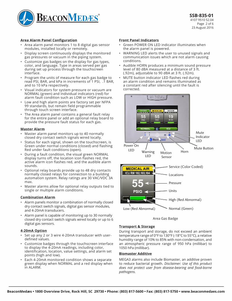
Front Panel Indicators• Green POWER ON LED indicator illuminates when
the alarm panel is powered. • WARNING LED alerts the user to unused signals and
communication issues which are not alarm causing conditions.
• Audible HORN produces a minimum sound pressure level of 80 dBA measured at a distance of 3 ft. (.92m), adjustable to 90 dBA at 3 ft. (.92m).
• MUTE button indicator LED flashes red during an alarm condition and remains illuminated as a constant red after silencing until the fault is corrected.
Power On LED
Mute Indicator LED
Mute ButtonHornMotion
SensorWarning
LED
Low (Red Abnormal) Normal (Green)
High (Red Abnormal)
Units
Pressure
Locations
Service (Color Coded)
Area Gas Badge
Transport & StorageDuring transport and storage, do not exceed an ambient temperature range of 0°F to 130°F (-18°C to 55°C), a relative humidity range of 10% to 85% with non-condensation, and an atmospheric pressure range of 950 hPa (millibar) to 1050 hPa (millibar).
Biomaster AdditiveMEGA3 alarms also include Biomaster, an additive proven to reduce bacterial growth. Disclaimer: Use of this product does not protect user from disease-bearing and food-borne pathogens.

SSB-835-014107 9510 52.04
Page 3 of 623 August 2016
BeaconMedæs • 1800 Overview Drive, Rock Hill, SC 29730 • Phone: (803) 817-5600 • Fax: (803) 817-5750 • www.beaconmedaes.com
MEGA3™ Alarm: In Alarm
MEGA3™ Alarm: Set Up
Area Alarm Panel: Custom Badge Set Up• Area Alarm panels are factory set with the ordered
gas badges.• Custom configurations are possible (gas colors, gas
names, units, low/high set points). Apply to gas sensors or 4-20mA inputs.
Custom LabelingAlphanumeric keyboard functionality on touchscreen allows for custom labeling. Customize source signals, gas texts, panel locations, and areas monitored.
Main Display Screens in Alarm
Active Alarm Screen
The Active Alarm screen provides detailed information about pressure or signals that are in alarm condition: • Gas Type• Gas Location• Gas Pressure or Signal.The alarm panel ships with the default response of switching to the Active Alarm screen upon an alarm condition. An option for the alarm to remain on the main screen is available through the set up process. With either option, toggling between the Main Display Screen and Active Alarm screen is possible.
MEGA3™ Alarm: Easy to Navigate Toolbar
Alarm Status (normal) Location of PanelHome Button Home Button Information Button
Alarm Button ConfigurationButton
Normal Toolbar
The Normal toolbar is available when the alarm is operating in normal status. To switch to the Icon toolbar, touch the Home button.
Icon Toolbar

SSB-835-014107 9510 52.04
Page 4 of 623 August 2016
BeaconMedæs • 1800 Overview Drive, Rock Hill, SC 29730 • Phone: (803) 817-5600 • Fax: (803) 817-5750 • www.beaconmedaes.com BeaconMedæs • 1800 Overview Drive, Rock Hill, SC 29730 • Phone: (803) 817-5600 • Fax: (803) 817-5750 • www.beaconmedaes.com
MEGA3™ Alarm Models
Example: Master Alarm with 20 input signals
Example Model Number: M3-M10
Example: Area Alarm with 3 gases - Oxgyen, Medical Air and Medical Vacuum
Example Model Number: M3-A10-OAV
Example: Combination Alarm with 10 Inputs, 6 Relay Outputs, and 3 gases - Oxygen, Medical Air, and Medical Vacuum
Example Model Number: M3-C01-OAV
Example: Combination Alarm with 7 Inputs, 6 Relay Outputs, 4 4-20mA devices, and 2 gases - Oxygen, Medical Air
Example Model Number: M3-C44-OA
M3 - ___ - __B C
Variable BAlarm Type and Size
Allowable Value
Description
M10 Master, 20 Inputs
M11 Master, 20 Inputs, 16 Relay Outputs
M12 Master, 20 Inputs, 32 Relay Outputs
M13 Master, 20 Inputs, 48 Relay Outputs
M20 Master, 40 Inputs
M21 Master, 40 Inputs, 16 Relay Outputs
M22 Master, 40 Inputs, 32 Relay Outputs
A10 Area Alarm, Up to 8 Area Gases
C01 Combination, 10 Inputs, 6 Relay Outputs, Up to 3 Area Gases
C10* Combination, 20 Inputs, Up to 6 Area Gases
C11* Combination, 20 Inputs, 16 Relay Outputs, Up to 6 Area Gases
C12* Combination, 20 Inputs, 32 Relay Outputs, Up to 6 Area Gases
C40 Combination, 7 Inputs, 6 Relay Outputs, 4 Inputs for 4-20mA devices
C41* Combination, 27 Inputs, 6 Relay Outputs, 4 Inputs for 4-20mA devices
C44*Combintation, 7 Inputs, 6 Relay Outputs, 4 Inputs for 4-20mA devices, Up to 6 Area Gases
Notes:
* Limitations on Combination Panels:• C10, C11, C12 Combinations
x 0-10 source signal Inputs used, Display up to 6 Area gases x 11-20 source signal Inputs used, Display up to 4 Area gases
• C41 x 0-20 source signal Inputs used, Display up to 4 4-20mA
devices x 21-27 source signal Inputs used, Display up to two 4-20mA
devices• C44
x Display up to 6 gas badges maximum, combination of 4-20mA and area gases, with maximum 4 4-20mA badges.
Variable CGas Type (Area and Combination Only)
Allowable Value
Description
O Oxygen
X Nitrous Oxide
A Medical Air
V Medical Vacuum
W WAGD
N Nitrogen
C Carbon Dioxide (CO2)
D Oxygen 100 psig
F Medical Air 100 psig
G Carbon Dioxide 100 psig
9 Instrument Air
1 CO2-O2 (CO2 over 7%)
2 O2-CO2 (CO2 not over 7%)
3 HE-O2 (HE over 80%)
4 O2-HE (HE not over 80%)
7 Laboratory Air
8 Laboratory Vacuum
H Helium
J Argon
S Surgical Air
B AGSS
E N2O-O2
M Mixed Gas
Patent Pending
© BeaconMedæs 08-23-16
SSB-835-014107 9510 52.04
Page 5 of 623 August 2016
BeaconMedæs • 1800 Overview Drive, Rock Hill, SC 29730 • Phone: (803) 817-5600 • Fax: (803) 817-5750 • www.beaconmedaes.com
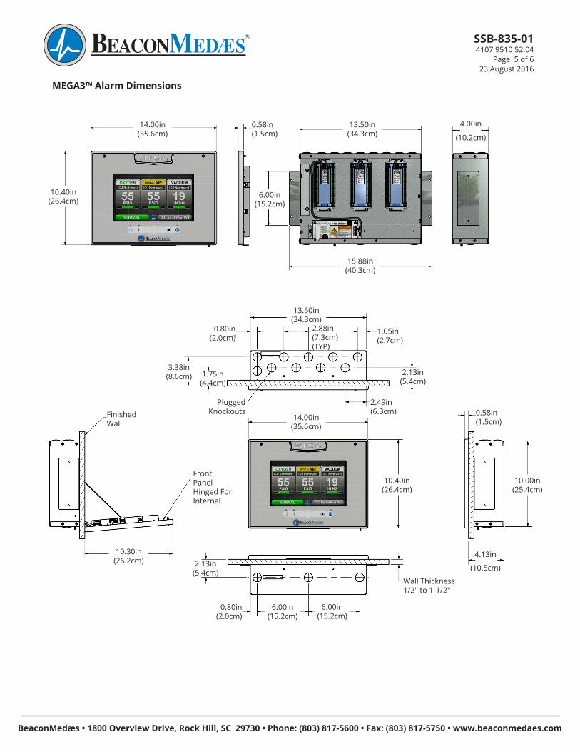
MEGA3™ Alarm Dimensions
14.00in(35.6cm)
4.00in
15.88in(40.3cm)
13.50in(34.3cm)
6.00in(15.2cm)
0.58in(1.5cm)
10.40in(26.4cm)
(10.2cm)
13.50in(34.3cm)
10.00in(25.4cm)
0.58in(1.5cm)
Plugged Knockouts
3.38in(8.6cm)
2.49in(6.3cm)
2.13in(5.4cm)
2.88in(7.3cm)(TYP)
0.80in(2.0cm)
1.05in(2.7cm)
1.75in(4.4cm)
10.40in(26.4cm)
(10.5cm)
4.13in
14.00in(35.6cm)
Wall Thickness 1/2" to 1-1/2"
Front Panel Hinged For Internal
10.30in(26.2cm)
Finished Wall
0.80in(2.0cm)
6.00in(15.2cm)
6.00in(15.2cm)
2.13in(5.4cm)

SSB-835-014107 9510 52.04
Page 6 of 623 August 2016
BeaconMedæs1800 Overview DriveRock Hill, SC 29730Phone: (803) 817-5600Fax: (803) 817-5750www.beaconmedaes.com ISO 13485 OHSAS 18001
MEGA3™ Area Alarm Gas Sensor Installation
Local Sensor Installation
Zone Valve Box Sensor Installation
(For Zone Valve Box mounting, an additional Installation Kit is required, part number 4107 4016 25 for each sensor)
Remote Sensor Installation
MEGA3™ Alarm: Additional Components
Gas Sensor Module OptionsPart Number Gas Type Sensor Assembly
4107 4016 75 Oxygen
4107 4016 76 Nitrous Oxide
4107 4016 77 Medical Air
4107 4016 78 Medical Vacuum
4107 4016 79 Nitrogen
4107 4016 80 Instrument Air
4107 4016 81 WAGD
4107 4016 82 Carbon Dioxide
4107 4016 83 Carbon Dioxide/Oxygen
4107 4016 84 Oxygen/Carbon Dioxide
4107 4016 85 Helium/Oxygen
4107 4016 86 Oxygen/Helium
4107 4016 87 Helium
4107 4016 88 Laboratory Air
4107 4016 89 Laboratory Vacuum
4107 4016 90 Oxygen 100 psig
4107 4016 91 Medical Air 100 psig
4107 4016 92 Carbon Dioxide 100 psig
4107 4016 93 Argon
4107 4016 94 AGSS
4107 4016 95 Nitrous Oxide/Oxygen
Gas Sensor Assembly includes the Gas Specific Sensor, DISS Check Fitting, and Copper Tube.
TotalAlert Infinity™ alarms are expandable with additional modules, see Operation & Maintenance Manual for options and part numbers.
Gas Specific Sensor
Gas Specific DISS Check Fitting 7" Copper Tube 3/8" (1/2" outer diameter)