megohmmeter 1060 - aemc · 2020-02-10 · megohmmeter models 1050/1060. 5. chapter 1. introduction....
TRANSCRIPT
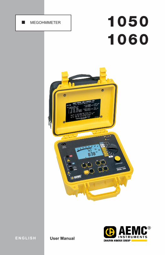
MEGOHMMETER 10501060
E N G L I S H User Manual
Statement of Compliance
Chauvin Arnoux®, Inc. d.b.a. AEMC® Instruments certifies that this instrument has been calibrated using standards and instruments traceable to international standards.
We guarantee that at the time of shipping your instrument has met its published specifications.
An NIST traceable certificate may be requested at the time of purchase, or obtained by returning the instrument to our repair and calibration facility, for a nominal charge.
The recommended calibration interval for this instrument is 12 months and begins on the date of receipt by the customer. For recalibration, please use our calibration services. Refer to our repair and calibration section at www.aemc.com.
Serial #: ________________________________
Catalog #: 2130.01 / 2130.03
Model #: 1050 / 1060
Please fill in the appropriate date as indicated:
Date Received: _________________________________
Date Calibration Due: _______________________
Chauvin Arnoux®, Inc.d.b.a AEMC® Instrumentswww.aemc.com
2 Megohmmeter Models 1050 /1060
Table of Contents
1. INTRODUCTION ................................................................................. 51.1 International Electrical Symbols ...........................................................5
1.2 DefinitionofMeasurementCategories .................................................6
1.3 ReceivingYourShipment .....................................................................6
1.4 OrderingInformation ............................................................................61.4.1 AccessoriesandReplacementParts ......................................71.4.2 AccessoryInformation ............................................................7
2. PRODUCT FEATURES ......................................................................... 82.1 ControlFeatures ................................................................................10
2.2 DigitalDisplayFeatures .....................................................................11
2.3 Bargraph ............................................................................................11
2.4 Symbols .............................................................................................12
2.5 ButtonFunctions ................................................................................132.5.1 2ndButton .............................................................................132.5.2 V-TIMEButton .......................................................................132.5.3 R-DAR-PIR(t)Button ............................................................142.5.4 ALARMButton ......................................................................162.5.5 SMOOTHButton ...................................................................172.5.6 UP/DOWN Button ................................................................182.5.7 SET-UPButton(ConfiguringtheInstrument) ........................182.5.8 ClearingtheMemory.............................................................202.5.9 CommunicationRate(RS-232) .............................................202.5.10 LeadResistanceCompensation ...........................................202.5.11 DefaultDeviceConfiguration ................................................212.5.12 Blocking(Disabling)TestVoltages ........................................21
2.6 MeasurementFunctions.....................................................................212.6.1 AC/DCVoltage ......................................................................212.6.2 InsulationMeasurement........................................................222.6.3 Continuity(40Ω )/Resistance(400kΩ) ..................................23
Megohmmeter Models 1050 /1060 3
3. SPECIFICATIONS ............................................................................. 243.1 ReferenceConditions.........................................................................24
3.2 Voltage ...............................................................................................24
3.3 InsulationResistance .........................................................................24
3.4 Continuity ...........................................................................................28
3.5 Resistance .........................................................................................28
3.6 PowerSupply .....................................................................................29
3.7 MechanicalSpecifications ..................................................................30
3.8 EnvironmentalSpecifications .............................................................30
3.9 SafetySpecifications ..........................................................................30
4. OPERATION ..................................................................................... 314.1 MeasurementProcedure....................................................................31
4.2 InsulationMeasurement .....................................................................31
4.3 ContinuityMeasurement ....................................................................32
4.4 ResistanceMeasurement ..................................................................32
4.5 CapacitanceMeasurement ................................................................32
5. MEMORY / RS-232 (Model 1060) ............................................. 335.1 RS-232Specifications ........................................................................33
5.2 Saving/RecallingValues(MEM/MRButton) .....................................33
5.3 PrintingMeasuredValues ..................................................................35
5.4 InstantaneousPrintingofMeasurements(PRINTbutton) .................36
5.5 PrintingDatainMemory(PRINTMEMbutton) ..................................37
6. APPLICATION EXAMPLES ................................................................ 396.1 InsulationMeasurementsonElectricalInstallations ...............................39
6.2 MeasurementsonElectricalorTelecomCable ..................................39
6.3 InsulationMeasurementsonMotors ..................................................40

4 Megohmmeter Models 1050 /1060
7. USING DATAVIEW® .......................................................................... 417.1 InstallingDataView® ...........................................................................41
7.2 MegohmmeterControlPanel .............................................................42
8. MAINTENANCE ................................................................................ 448.1 BatteryReplacement(Model1050) ...................................................44
8.2 RechargingtheBattery(Model1060) ................................................45
8.3 FuseReplacement .............................................................................45
8.4 Cleaning .............................................................................................46
8.5 Storage...............................................................................................46
RepairandCalibration.................................................................................47
TechnicalandSalesAssistance ..................................................................47
LimitedWarranty .........................................................................................48
WarrantyRepairs ........................................................................................48
Megohmmeter Models 1050 /1060 5
CHAPTER 1
INTRODUCTION
WARNING Thesesafetywarningsareprovided toensure thesafetyofpersonnelandproperoperationoftheinstrument.
• Do not attempt to perform any testswith these instruments until youhavereadtheinstructionmanual.
• Safetyistheresponsibilityoftheoperator!• Testsaretobecarriedoutonlyonnon-energizedcircuits!Checkforlive
circuitsbeforemakingresistancemeasurements(safetycheck).• High voltage is present, as is the sample connected to it. Anyone
performingorassisting in testingmust followall safetyprecautions topreventelectricalshocktothemselvesandtoothers.
• Usepersonalprotectiveequipmentwhereappropriate.• When testing samples with a capacitive component, make sure they
havebeenproperlydischargedandaresafetotouch.Dielectricinsula-tionsamplesshouldbeshort-circuitedforatleastfivetimestheamountoftimetheywereenergized.
• Megohmmetersshouldneverbeusedinanexplosiveenvironment.• Usetheleadssuppliedwiththemegohmmeters.Iftheyaredefectiveor
worn,replacebeforetesting.• TheModel1060doesnotallowmeasurementstobecarriedoutduring
batterycharging.• Thisinstrumentcanbeusedoninstallationsratedfor600V,CategoryIII.
1.1 International Electrical Symbols
This symbol signifies that the instrument is protected by double or reinforced insulation.This symbol on the instrument indicates a WARNING and that the operator must refer to the user manual for instructions before operating the instrument. In this manual, the symbol preceding instructions indicates that if the instructions are not followed, bodily injury, installation/sample and product damage may result.Risk of electric shock. The voltage at the parts marked with this symbol may be dangerous.
In conformity with WEEE 2002/96/EC
6 Megohmmeter Models 1050 /1060
1.2 Definition of Measurement CategoriesCAT IV: Formeasurementsperformedattheprimaryelectricalsupply(<1000V)
suchasonprimaryovercurrentprotectiondevices,ripplecontrolunits,or meters.
CAT III: Formeasurementsperformedinthebuildinginstallationatthedistributionlevel such as on hardwired equipment in fixed installation and circuitbreakers.
CAT II: Formeasurementsperformedoncircuitsdirectlyconnectedtotheelec-trical distribution system. Examples aremeasurements on householdappliancesorportabletools.
1.3 Receiving Your ShipmentUponreceivingyourshipment,makesurethatthecontentsareconsistentwiththepackinglist.Notifyyourdistributorofanymissingitems.Iftheequipmentappearstobedamaged,fileaclaimimmediatelywiththecarrierandnotifyyourdistributoratonce,givingadetaileddescriptionofanydamage.Savethedamagedpackingcontainertosubstantiateyourclaim.
NOTE: Charge the instrument fully before use (Model 1060).
1.4 Ordering InformationMegohmmeter Model 1050.............................................................Cat. #2130.01Includes detachable accessory pouch (one red, one blue test lead, one black shielded lead, three color-coded (black, red and blue) alligator clips, one black test probe), batteries, spare fuses and a user manual.
Megohmmeter Model 1060.............................................................Cat. #2130.03Includes detachable accessory pouch (one red, one blue test lead, one black shielded lead, three color-coded (black, red and blue) alligator clips, one black test probe; one RS-232 DB9 F/F 6 ft null modem cable, RS-232 to USB adapter, US 115V power cord, spare fuses, rechargeable battery, and a USB stick with DataView® software and a user manual.
NOTE: Sparefuseandcliparelocatedinsidetheinstrument’scase.
Megohmmeter Models 1050 /1060 7
1.4.1 Accessories and Replacement PartsRemoteTestProbe ........................................................................... Cat. #2118.97Cable,PCRS-232,DB9F/F6ftNullModemCable(1060)............. Cat. #2119.45Fuse,Setof3,0.1A,660V ............................................................... Cat. #2119.56Fuse,Setof1,2.5A,1200V ............................................................. Cat. #2119.57Lead,ReplacementSet(1red,1bluetestlead,1blackshielded lead,3color-codedalligatorclips,1blacktestprobe,noRScable) ..... Cat. #2119.58Inverter – 12VDC to 120VAC200WattforVehicleuse ......................Cat. #2135.43Lead,Setof3Color-coded10ftSafetyLeads.................................Cat. #2951.70Replacement9.6VRechargeableBatteryPack(1060) ....................Cat. #2960.21
US115VPowerCord .......................................................................Cat. #5000.14
Adapter–RS-232toUSB2.0(1060) ...............................................Cat. #5000.60
Order Accessories and Replacement Parts Directly OnlineCheck our Storefront at www.aemc.com/store for availability
1.4.2 Accessory Information
Remote Test Probe• Theyellowtestbuttongeneratesthetestvoltagewhenpressed.• The push-button on the back of the probe allows you to light the test point
(approx500luxoflight).Thisfunctionisveryuseful,sinceinsulationtestingisperformedonde-energizedinstallations,whichcanbeinadarkarea.
DataView® Software (Model 1060)
• Retrievedatafrommemoryandplotgraphsofthechangesininsulationasafunctionofthetimeoverwhichthetestvoltageisapplied,R(t).
• Printoutprotocolsofpersonalizedtests(dependingontheuser’sneeds).• Createtextfilesforuseonspreadsheets.
8 Megohmmeter Models 1050 /1060
CHAPTER 2
PRODUCT FEATURES
TheMegohmmetersModels1050and1060areportable instrumentshousedinruggedcasing.TheModel1050uses1.5V(Ccell)alkalinebatteries.TheModel1060usesarechargeablebatteryandACpower.Model 1060: Measurements cannot be performed during battery charging.Thesemegohmmetersaredesignedtocheckthesafetyofelectricalinstallationsandequipment.
Units Measure:• Voltage• InsulationResistance• Continuity• Resistance • Capacitance
Advantages: • Digitalfilteringofinsulationmeasurements• Measuringwiththeremotecontrolprobe• Automaticvoltagemeasurementinallfunctions• AutomaticdetectionofexternalACorDCvoltagesontheterminals• Thresholdprogrammingineachfunction,triggeringaudiblealarms• Timedcontrolofmeasurementduration• Fuseprotection,withdefectivefusedetectionandindication• Automaticdischargeofresidualhighvoltageonthetesteddevice• Automaticshut-offtosavethebatteries• Batterylevelindicator(1050)orbatterychargestatusindicator(1060)• Largeeasy-to-readback-litLCD
Additional Features (Model 1060 only): • Integralrechargeablebattery• 128kBmemory,real-timeclockandserialinterface• ControlandprogrammingoftheinstrumentfromaPC (withDataView®software)

Megohmmeter Models 1050 /1060 9
MODEL 1050
!
V/TIME
R-DAR-PI
MEGOHMMETERMODEL 1050
START/STOP
400 KΩ
SET-UP
G
600V CAT III
OFF
40Ω
MΩ-1000V
MΩ - 500V
MΩ - 250V
MΩ -100V
MΩ - 50V
2nd
SMOOTH ALARM
R(t)
5
3
2
4
1
8.8.8.8
0.1M1M 10M 100M 1G 10G 100G
1T
µA nA µF
COM
P
GΩPI
DAR
ALARM
TΩ
MΩ kΩ
MEM MR
SMOOTH REMOTE
OBJ.
Ω
min sec
TEST
V DCAC
2nd 8.8.8.8
MODEL 1060
!
!!
V/TIME
R-DAR-PI
MEGOHMMETERMODEL 1060
START/STOP
RS-23285-256 V
50/60 Hz
MEM PRINT
400 KΩ
SET-UP
G
600V CAT III
OFF
40Ω
MΩ-1000V
MΩ - 500V
MΩ - 250V
MΩ -100V
MΩ - 50V
2nd
SMOOTH ALARM
R(t)MR PRINT MEM
5
3
2
6
4
1
7
8.8.8.8
0.1M1M 10M 100M 1G 10G 100G
1T
µA nA µF
COM
P
GΩPI
DAR
ALARM
TΩ
MΩ kΩ
MEM MR
SMOOTH REMOTE
OBJ.
Ω
min sec
TEST
V DCAC
2nd 8.8.8.8
10 Megohmmeter Models 1050 /1060
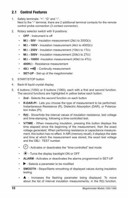
2.1 Control Features
1. Safetyterminals:“+”,“G”and“-”.Nexttothe“-”terminal,thereare2additionalterminalcontactsfortheremotecontrolprobeconnection(3contactconnector).
2. Rotaryselectorswitchwith9positions:• OFF-Instrumentisoff• MΩ - 50V-Insulationmeasurement(2kΩ to 200GΩ)
• MΩ - 100V-Insulationmeasurement(4kΩ to 400GΩ)
• MΩ - 250V-Insulationmeasurement(10kΩ to 1TΩ)
• MΩ - 500V-Insulationmeasurement(20kΩ to 2TΩ)
• MΩ - 1000V-Insulationmeasurement(40kΩ to 4TΩ)
• 400KΩ-Resistancemeasurement• 40Ω -Continuitymeasurement• SET-UP-Set-upofthemegohmmeter
3. START/STOPbutton
4. Back-litliquidcrystaldisplay
5. 6buttons(1050)or8buttons(1060),eachwithafirstandsecondfunction.Thesecondfunctionsarehighlightedinyellowbeloweachbutton:• 2nd-Selectsthesecondfunctiononeachbutton• R-DAR-PI-Letsyouchoosethetypeofmeasurementtobeperformed.
InstantaneousResistance(R),DielectricAbsorption(DAR),orPolariza-tionIndex(PI).
• R(t)-Show/hidetheintervalvaluesofinsulationresistance,testvoltageandtime-stamping,followingatime-controlledtest.
• V/TIME -Whenmeasuring insulation,pressing thisbuttondisplays thetimeelapsed since the beginning of themeasurement, then the exactvoltagegenerated.Whenperformingresistanceorcapacitancemeasure-ment,thisbuttonhasnoeffect.InMR(memoryrecall),itdisplaysthedateandtimeatwhichthemeasurementwasstored, theexact testvoltageandtheOBJ:TESTnumber.
• -Activatesordeactivatesthe“time-controlled”testmode
• -TurnsthedisplaybacklightONorOFF• ALARM-ActivatesordeactivatesthealarmsprogrammedinSET-UP
• -Selectsaparametertobemodified• SMOOTH-Stops/Startssmoothingofdisplayedvaluesduringinsulation
testing
• - Increases the flashing parameter being displayed. To moveabout the list of interval insulationmeasurements, in theR(t) function.

Megohmmeter Models 1050 /1060 11
• - Decreases the flashing parameter being displayed. To moveabout the list of interval insulationmeasurements in theR(t) function.Ifthe and buttonsarehelddown,themovementbetweenparam-etersisincreasedtoafasterrate.
Model 1060 only:• MEM-Savesmeasuredvalues• MR - Recalls saved data• PRINT-Printsmeasurementresults• PRINT MEM-Printsmemorycontents
6. RS-232serialinterfacemaleplug(9-pin)forconnectiontoaPC.
2.2 Digital Display Features
Main Display Indicates:• Insulationmeasurement(resistance,DARandPI,capacitance)• Continuitymeasurement• Resistancemeasurement
Small Display Indicates:• Voltagemeasuredorappliedbytheinstrument• Elapsedtimeortheoutputvoltage,duringinsulationmeasurement
Afterrecordingdata(1060),thesmalldisplayalsoindicatesthetimeanddateinMR(memoryrecall)mode,andthememoryaddresswiththeOBJ:TESTnumber.
2.3 Bargraph• Activeduringinsulationmeasurement(0.1MΩ to 1TΩ).• Indicatesthebatterychargeatstart-up.• Indicatesfreememoryspace-onesegmentrepresentingapproximately
100groupsofsavedvalues,witheachgroupholdingapproximately50recordings(1OBJand1TEST).
12 Megohmmeter Models 1050 /1060
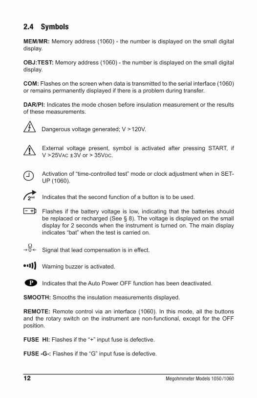
2.4 Symbols
MEM/MR:Memoryaddress(1060)-thenumberisdisplayedonthesmalldigitaldisplay.
OBJ:TEST: Memoryaddress(1060)-thenumberisdisplayedonthesmalldigitaldisplay.
COM:Flashesonthescreenwhendataistransmittedtotheserialinterface(1060)orremainspermanentlydisplayedifthereisaproblemduringtransfer.
DAR/PI: Indicatesthemodechosenbeforeinsulationmeasurementortheresultsofthesemeasurements.
Dangerousvoltagegenerated;V>120V.
External voltage present, symbol is activated after pressing START, ifV>25VAC±3Vor>35VDC.
Activationof“time-controlledtest”modeorclockadjustmentwheninSET-UP(1060).
Indicatesthatthesecondfunctionofabuttonistobeused.
Flashes if the battery voltage is low, indicating that the batteries shouldbereplacedorrecharged(See§8).Thevoltageisdisplayedonthesmalldisplayfor2secondswhentheinstrumentisturnedon.Themaindisplayindicates“bat”whenthetestiscarriedon.
Signalthatleadcompensationisineffect.
Warningbuzzerisactivated.
IndicatesthattheAutoPowerOFFfunctionhasbeendeactivated.
SMOOTH:Smoothstheinsulationmeasurementsdisplayed.
REMOTE: Remotecontrolviaan interface (1060). In thismode,all thebuttonsand the rotary switchon the instrumentarenon-functional, except for theOFFposition.
FUSE HI: Flashesifthe“+”inputfuseisdefective.
FUSE -G-: Flashesifthe“G”inputfuseisdefective.
Megohmmeter Models 1050 /1060 13
2.5 Button Functions
2.5.1 2nd Button
• Selectsthesecondfunction(highlightedinyellow)onthebuttons.
• The symbolappears.Thissymboldisappearsuponpressingthefunctionbuttonchosen,exceptifthebuttonisactivated.Inthiscase,itonlydisap-pearswhen the button ispressedagain,or ifother functionbuttonsarepressed.Thisallowsyou to rapidlydecreaseparameterswith the button,withouthavingtopressthe buttoneverytime.
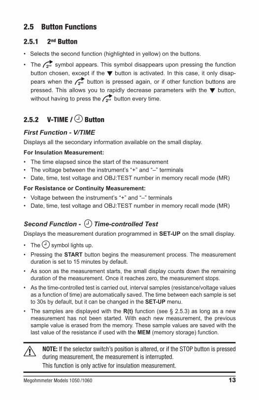
2.5.2 V-TIME / Button
First Function - V/TIMEDisplaysallthesecondaryinformationavailableonthesmalldisplay.
For Insulation Measurement:• Thetimeelapsedsincethestartofthemeasurement• Thevoltagebetweentheinstrument’s“+”and“–”terminals• Date,time,testvoltageandOBJ:TESTnumberinmemoryrecallmode(MR)
For Resistance or Continuity Measurement: • Voltagebetweentheinstrument’s“+”and“–”terminals• Date,time,testvoltageandOBJ:TESTnumberinmemoryrecallmode(MR)
Second Function - Time-controlled TestDisplaysthemeasurementdurationprogrammedinSET-UPonthesmalldisplay.
• The symbollightsup.• PressingtheSTARTbuttonbeginsthemeasurementprocess.Themeasurement
durationissetto15minutesbydefault.• Assoonasthemeasurementstarts,thesmalldisplaycountsdowntheremaining
durationofthemeasurement.Onceitreacheszero,themeasurementstops.• Asthetime-controlledtestiscarriedout,intervalsamples(resistance/voltagevalues
asafunctionoftime)areautomaticallysaved.Thetimebetweeneachsampleissetto30sbydefault,butitcanbechangedintheSET-UPmenu.
• Thesamplesaredisplayedwith theR(t) function(see§2.5.3)as longasanewmeasurement has not been started.With each newmeasurement, the previoussamplevalueiserasedfromthememory.ThesesamplevaluesaresavedwiththelastvalueoftheresistanceifusedwiththeMEM (memorystorage)function.
NOTE: If the selector switch’s position is altered, or if the STOP button is pressed during measurement, the measurement is interrupted.
This function is only active for insulation measurement.
14 Megohmmeter Models 1050 /1060
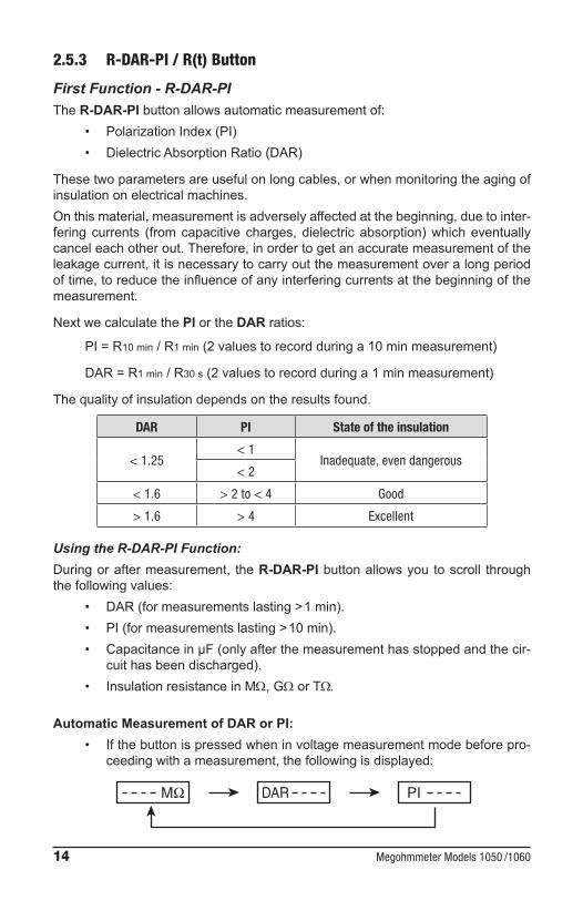
2.5.3 R-DAR-PI / R(t) Button
First Function - R-DAR-PITheR-DAR-PIbuttonallowsautomaticmeasurementof:
• PolarizationIndex(PI)• DielectricAbsorptionRatio(DAR)
Thesetwoparametersareusefulonlongcables,orwhenmonitoringtheagingofinsulationonelectricalmachines.Onthismaterial,measurementisadverselyaffectedatthebeginning,duetointer-feringcurrents (fromcapacitivecharges,dielectricabsorption)whicheventuallycanceleachotherout.Therefore,inordertogetanaccuratemeasurementoftheleakagecurrent,itisnecessarytocarryoutthemeasurementoveralongperiodoftime,toreducetheinfluenceofanyinterferingcurrentsatthebeginningofthemeasurement.
NextwecalculatethePIortheDAR ratios:
PI=R10 min/R1 min(2valuestorecordduringa10minmeasurement)
DAR=R1 min/R30 s(2valuestorecordduringa1minmeasurement)
Thequalityofinsulationdependsontheresultsfound.
DAR PI State of the insulation
< 1.25< 1
Inadequate, even dangerous< 2
< 1.6 > 2 to < 4 Good
> 1.6 > 4 Excellent
Using the R-DAR-PI Function:Duringoraftermeasurement, theR-DAR-PI buttonallowsyoutoscroll throughthefollowingvalues:
• DAR(formeasurementslasting>1min).• PI(formeasurementslasting>10min).• CapacitanceinµF(onlyafterthemeasurementhasstoppedandthecir-
cuithasbeendischarged).• InsulationresistanceinMΩ,GΩ or TΩ.
Automatic Measurement of DAR or PI:• Ifthebuttonispressedwheninvoltagemeasurementmodebeforepro-
ceedingwithameasurement,thefollowingisdisplayed:
MΩ DAR PI
Megohmmeter Models 1050 /1060 15
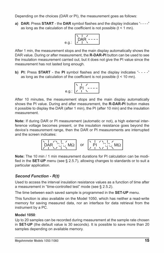
Dependingonthechoices(DARorPI),themeasurementgoesasfollows:
a) DAR: PressSTART-theDARsymbolflashesandthedisplayindicates“----”aslongasthecalculationofthecoefficientisnotpossible(t<1mn).
e.g.: DAR
After1min,themeasurementstopsandthemaindisplayautomaticallyshowstheDARvalue.Duringoraftermeasurement,theR-DAR-PIbuttoncanbeusedtoseetheinsulationmeasurementcarriedout,butitdoesnotgivethePIvaluesincethemeasurementhasnotlastedlongenough.
b) PI:PressSTART - thePI symbol flashesand thedisplay indicates “- - - -”aslongasthecalculationofthecoefficientisnotpossible(t<10mn).
e.g.: PI
After 10 minutes, the measurement stops and the main display automaticallyshowsthePIvalue.Duringandaftermeasurement,theR-DAR-PIbuttonmakesitpossibletodisplaytheDAR(after1min),thePI(after10min)andtheinsulationmeasurement.
Note: IfduringDARorPImeasurement(automaticornot),ahighexternalinter-ferencevoltagebecomespresent,or the insulation resistancegoesbeyond thedevice’smeasurementrange,thentheDARorPImeasurementsareinterruptedandthescreenindicates:
DAR orMΩ PI MΩ
Note: The10min/1minmeasurementdurationsforPIcalculationcanbemodi-fiedintheSET-UPmenu(see§2.5.7),allowingchangestostandardsortosuitaparticularapplication.
Second Function - R(t)Usedtoaccesstheintervalinsulationresistancevaluesasafunctionoftimeafterameasurementin“time-controlledtest”mode(see§2.5.2).ThetimebetweeneachsavedsampleisprogrammedintheSET-UPmenu.ThisfunctionisalsoavailableontheModel1050,whichhasneitheraread-writememory for savingmeasured data, nor an interface for data retrieval from theinstrumentbyaPC.
Model 1050:Upto20samplescanberecordedduringmeasurementatthesampleratechosenin SET-UP(thedefaultvalueis30seconds).Itispossibletosavemorethan20samplesdependingonavailablememory.

16 Megohmmeter Models 1050 /1060
Model 1060:Thenumberofsamplesthatcanbesavedisonlylimitedbythememoryspaceavailable. Toenterthedisplaymode,presstheR(t)button:
• Thesmalldisplayindicatesthetime00:30(e.g.thesamplingfrequencyisevery30s).
• ThemaindisplayshowsthecorrespondingRvalue.
UsetheV/TIMEbuttontoalternatebetweenthevoltageandtime(onthesmalldisplay),associatedwiththeRvalueonthemaindisplay.
The button is used to scroll down through theall the samples savedduringmeasurement,allowingyoutoreadtheinformationinordertodrawR(t)andV(t)graphs.ThismakesitpossibletocarryoutR(t)analysison-site,withoutaprinteroraPC.Toexitthisfunction,presstheR(t) or R-DAR-PIbuttonagain.
2.5.4 / ALARM Button
First Function - Turnsthedisplayback-lightON or OFF.
Second Function - ALARM Activates/deactivates theALARM function. The “ALARM” symbol is displayedwhenactivated.Ifactivated,andthehighorlowthresholdvaluesareprogrammed,the“ALARM” symbolflashesandthebuzzer(ifactivated)soundscontinuouslywhenthethresh-old is crossed. Itispossibletoprogramadifferentlimitineachfunction.Theselimitswillbestoredinmemoryevenafterthedeviceisturnedoff.
Activating the Alarm Indication before a TestToactivatetheAlarmIndicationbeforeperformingatestyoumustgothroughthefollowingsteps:
• ProgramtheAlarmSetPointResistanceValuefortheTestVoltageyouwillbeusing.
• TurntheRotaryswitchtotheSetupposition.• PresstheYellow2ndbuttonandthentheAlarmbuttontosetAlarms.The
firsttimeyoupress2nd&Alarmyouwillseethealarmsettingfor50volttests.
• Press2nd&Alarmbuttonsrepeatedlyuntilyouseethetestyouwishtosetalarmsforinthetoplineofthedisplay.Thesequencingwillbe50,100,250,500,1000,ResandCont.
Megohmmeter Models 1050 /1060 17
• UsethecursorkeystoadjusttheBlinkingvalue.FirstselectKΩ, MΩ, GΩ or TΩusingtheUpArrowKey().
• Next,presstheRightArrowKey()tomovetothenextselectionwhichis thegreater than(>) / less than(<)choice.Use the tomakeyourselection.
• PresstheagaintomovetotheResistanceValueSetPointSelection.You can change this valuedigit by digit using the / combination workingfromthehighesttolowestdigit.
• Whenfinishedprogrammingthealarmsettings,placetherotaryswitchtothedesiredtestfunction.
• Beforeinitiatingatest,presstheYellow2ndbuttonandtheAlarmbuttontoactivatetheAlarmNotification.Theword“ALARM”willappearinthelowerleftsideofthedisplay.
• Next,presstheroundyellowStart/Stopbuttontobeginthetest.TheAlarmsymbolwillflashandthebuzzerwillsoundcontinuouslyiftheAlarmsetpointistripped.
NOTE: If the rotary switch is turned off prior to the next test, the alarm notification will be deactivated. You will need to press the Yellow 2nd button and the Alarm button to activate the Alarm Notification when you turn the unit back on before starting the next test, if alarm notification is desired.
2.5.5 / SMOOTH Button
First Function - Selectsthedesiredparametertobemodified-theselectedparameterflashes.
Itismodifiedusingthe button(see§2.5.6).
Second Function - SMOOTHActivatesadigitalfilter for insulationmeasurement. Itonlyhasaneffecton thedisplayedvalues(whicharesmoothed)andnottheactualmeasurements.Forexample,thisfunctionisusefulwhenthedisplayedinsulationvaluesarehighlyunstable,broughtaboutduetoacapacitivecomponentinthetestedelement.
18 Megohmmeter Models 1050 /1060
2.5.6 ButtonChangestheflashingparametersdisplayed,orviewsR(t)values(see§2.5.3).As a general rule, two figures (day, month, hour, min., sec., and OBJ:TEST)flash.The and functionshavea“follow-on”mode.(e.g.assoonasthehighorlowprogramlimitisreached,theparametertobemodifiedswitchesautomaticallytothefollowingloworhighlimit.)
First Function • Pressbuttonbrieflytoincreasethedisplayednumberslowly• Pressbuttonforalongertimetoincreaseatafasterrate
Second Function • Pressbuttonbrieflytodecreasethedisplayednumberslowly• Pressbuttonforalongertimetodecreaseatafasterrate
Unlikeall thesecondfunctionsofotherbuttons, it isnotnecessarytopressthe buttoneachtimetogettothefunction.The symbolremainsdisplayed
andisvalidforthefunction(only),aslongastheuserdoesnotdeactivateitbypressing oranotherbutton.
2.5.7 SET-UP Button (Configuring the Instrument)
AfterselectingSET-UPwiththerotaryselectorswitch:• Allthedisplaysegmentsarelitupfor1second• Thesoftwareversionnumberisdisplayed• Theinstrumentserialnumberisdisplayed• “PUSH”comesuponthesmalldisplayand“btn”onthemaindisplay,
invitingtheoperatortopressabutton
The SET-UP function is used to directly access the parameters to be pro-grammed, by pressing the corresponding button:
• After having pressed a button, the corresponding figures or symbolsappearonthescreen
• Thefiguresorthesymbolsthatcanbemodifiedflashonthescreen• Usethe and buttons• Alltheparametersareimmediatelyandpermanentlysaved
Megohmmeter Models 1050 /1060 19
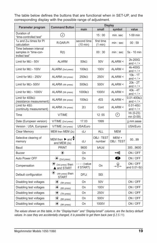
ThetablebelowdefinesthebuttonsthatarefunctionalwheninSET-UP,andthecorrespondingdisplaywiththepossiblerangeofadjustment.
Parameter program Command Button Displaymain small symbol value
Durationof“time-controlledtest” 15:00 min. sec 1-59 min
1st and 2ndtimesforPIcalculation R-DAR-PI second time
(10min)firsttime(1min) min:sec 00:59
Timebetweenintervalsamplesin“time-con-trolledtest”
R(t) 00:30 min:sec 5s - 10 min
LimitforMΩ - 50V ALARM 50kΩ 50V ALARM< 2k-200G and</>
LimitforMΩ - 100V ALARM (2ndpress) 100kΩ 100V ALARM< 4k-400G and</>
LimitforMΩ - 250V ALARM (3rdpress) 250kΩ 250V ALARM< 10k - 1T and</>
LimitforMΩ- 500V ALARM (4thpress) 500kΩ 500V ALARM< 20k - 2T and</>
LimitforMΩ - 1000V ALARM (5thpress) 1000kΩ 1000V ALARM< 40k - 4T and</>
Limitfor400kΩ(resistancemeasurement) ALARM (6thpress) 100kΩ rES ALARM< 0.01-400kΩ
and</>Limitfor40Ω(continuitymeasurement) ALARM (7thpress) 2Ω Cont ALARM< 0.01-40Ω
and</>
Time V/TIME 12:55 hh(0-23)mn(0-59)
Date(Europeanversion) V/TIME(2ndpress) 17.03 1999 jj.mm.aaaaVersion:USA,European V/TIME(3rdpress) USA/Euro USA/EuroClearMemory MEM then MEM (2s) cLr ALL MEM
Selectiveclearingofmemory MEMthen and
and MEM (2s) cLrOBJ:TESTnumber
MEM+OBJ:TEST 00...99
Baud PRINT 9600 bAUd 300...9600Buzzer On ON/OFF
AutoPowerOFF (2ndpress) On ON/OFF
Compensation (3rdpress)then and START
----(valueifSTART) On
ON/OFFand 0.01-5Ω
Defaultconfiguration (4thpress)thenSTART
DFLt SEt
Disablingtestvoltages (5thpress) On 50V ON/OFF
Disablingtestvoltages (6thpress) On 100V ON/OFF
Disablingtestvoltages (7thpress) On 250V ON/OFF
Disablingtestvoltages (8thpress) On 500V ON/OFF
Disablingtestvoltages (9thpress) On 1000V ON/OFF
The values shown on this table, in the “Display/main” and “Display/small” columns, are the factory default values. In case they are accidentally changed, it is possible to get them back (see § 2.5.11).

20 Megohmmeter Models 1050 /1060
2.5.8 Clearing the Memory
In SET-UP,presstheMEMbutton:• TheMEMsymbolflashes• Thesmalldisplayindicates“ALL”• Themaindisplayindicates“cLR”
To clear the entire memory,presstheMEMbuttonagainfor2seconds:• TheMEMsymbolisdisplayedwithoutflashing• Themaindisplayindicates“FrEE”
To clear the contents of a specific OBJ : TEST number:• Selectthenumberusingthe and buttons• “cLr”remainsdisplayedonthemaindisplay
PresstheMEMbuttonagainfor2secondstoclearthecontents:• ThesmalldisplayindicatestheOBJ : TESTnumber• Themaindisplayindicates“FrEE”
2.5.9 Communication Rate (RS-232)• In SET-UP,pressthePRINTbutton.• Themain display indicates theCommunicationRate (300, 600, 1200,
2400,4800,9600orParallel).• “baud”appearsonthesmalldisplay.Thevaluecanbechangedusing
the and buttons.• “Parallel” appearing in the displaymeans that the parallelmode has
beenselected.Thisisforprintingonaparallelprinter.
2.5.10 Lead Resistance Compensation
In SET-UP,pressthe buttonthreetimes.The symbol and ONappearsinthesmalldisplay.OFFcanbeselectedwiththe button.Inthisinstance,theleadresistancewillnotbesubtractedduringcontinuitymeasurement.To store the lead resistance:
• ConnectthemtogetherandpressSTART(inSET-UPposition )• Theresistanceoftheleadswillbestoredandindicatedonthemaindisplay
NOTE:• Thisvalueisstoredinmemory,evenwhentheinstrumentisswitchedOFF.• Theleadcompensationonlycomesintoeffectwhenperformingcontinu-
itymeasurements.
Megohmmeter Models 1050 /1060 21
• Toactivate/deactivatethisfunction,simplyselectON or OFFonthesmalldisplaywiththe button.
• Thevaluewillbestoredanddisplayedonthemaindisplay,butcanbeactivatedordeactivated,dependingonwhatthesmalldisplayindicates.
• Valuesbetween0 and 5Ωcanbesavedforleadcompensation.Beyondthisvalue,nothingissaved.
2.5.11 Default Device ConfigurationIn SET-UP,pressthe buttonfourtimes:
• “SEt” appearsinthesmalldisplay• “DFLt” appearsinthemaindisplay
PressSTARTtoselectthedefaultconfigurationsettings(seetheprevioustable).
2.5.12 Blocking (Disabling) Test VoltagesThisfunctionpreventsinsulationmeasurementsfrombeingcarriedoutatselectedtestvoltages.Thismakesitpossibletousetheinstrumentforspecificapplicationsandavoidimpropervoltages.
In SET-UP,pressthe button5timesormore(dependingonthevoltagetobedisabled):
• Thetestvoltagesappearinorderonthesmalldisplaywiththe symbol and ON/OFFonthemaindisplay.
• ChooseON or OFFusingthe buttonforeachtestvoltageyouwishtodisable(OFF)ortoreinstate(ON)foruseduringinsulationtestsatthesevoltages.
2.6 Measurement Functions
2.6.1 AC/DC Voltage• Selectanymeasurementpositionwiththerotaryselectorswitch.• TheinstrumentisautomaticallyinAC/DCvoltagemeasurementmode.• The voltage is continuouslymeasuredand is shownon the small dis-
play.
Measurement is prohibited if an external voltage is present at the terminals before pressing START/STOP. Similarly, if an interference voltage is detected during measurement, the measurement is stopped and that voltage is indicated.

22 Megohmmeter Models 1050 /1060
2.6.2 Insulation MeasurementAssoonasoneoftheMΩpositionshasbeenselected,themaindisplayshows“----MΩ”,andthesmalldisplayindicatesthevoltagepresentatthedevice’s“+”and“–”terminals.
If the external voltage present at the device’s terminals exceeds 25VAC/DC, pressing the yellow START/STOP button does not bring about insulation mea-surement, but instead triggers an audible signal. The symbol flashes for 2 seconds, then the device goes back to automatic voltage measurement.
If theexternal voltagepresent at thedevice terminals is below25VAC/DC, theninsulationmeasurementcanproceed.PressingSTARTimmediatelybeginsthemeasurement.Themeasurementvalueisdisplayedonthemaindigitaldisplayandonthebargraph.Anaudiblebeepisgivenoutevery10secondstoindicatethatmeasurementisinprogress.
If the test voltage is considered to be dangerous (>120V), the symbol is displayed. If, during insulation measurement, an external voltage >25VAC ±3V or 35VDC is detected, the measurement is stopped as long as the voltage is applied to the instrument. The symbol flashes and the voltage value is indicated on the small digital display.
Ifthemeasurementsfluctuategreatly,theSMOOTHfunctioncanbeenabled(see§2.5.5).
BypressingtheV/TIMEbuttonduringmeasurement,youcanalternatebetweendisplayingthedurationofthevoltagemeasurementandtheexactvoltagegener-atedonthesmalldisplay(see§2.5.2).
Pressing theSTOPbuttonstops themeasurement.After themeasurementhasbeenstoppedtheresultremainsdisplayed.
It ispossibletoscroll throughall theotherresultsavailableonthemaindisplayusingtheR-DAR-PIbutton.Thisbuttoncanalsobeusedbeforethemeasurementisbegun(see§2.5.3).
Ifthe“time-controlledtest”modehasbeenselected,theR(t)buttonmakesitpos-sibletoaccessallthesavedintervalmeasurementsautomatically(see§2.5.2and2.5.3).
IftheALARMfunctionisactivated,abuzzeristriggeredassoonasthemeasure-mentcrossesthethresholdprogrammedintheSET-UPconfigurationmenu(see§2.5.4).
Display of values after measurement Thefollowinginformationmaybedisplayed:

Megohmmeter Models 1050 /1060 23
R-DAR-PIButton V-TIME Button
MainDisplay Smalldisplay SmalldisplayiftheMRbuttonispressed(Model1060)
ResistanceDARPI
Capacitance*R(t)
duration(min.sec)duration(min.sec)duration(min.sec)
duration(min.sec)
date,time,testvoltage,OBJ:TESTdate,time,testvoltage,OBJ:TESTdate,time,testvoltage,OBJ:TEST
lastvoltage
*Capacitance (µF) measurement is only displayed after the measurement is finished and the circuit has been discharged.
2.6.3 Continuity (40Ω ) / Resistance (400kΩ)• Continuitymeasurementiscarriedoutonthe40Ωswitchposition (withatestcurrent>200mAupto20Ω)• Resistancemeasurementiscarriedoutonthe400kΩposition (withatestcurrent<6mA).
Oncetheselectorswitchhasbeenturnedtooneofthese2functionpositions,themaindisplayindicates----Ω(forcontinuity)or----kΩ(forresistance)andthesmalldisplayindicatesthevoltagepresentonthe“+”and“–”terminals.
If the voltage is >3VAC/DC and the START/STOP button is pressed, the symbol flashes and the audible alarm beeps (for 2 seconds) signaling that the measurement was denied. The instrument then goes back to its normal voltage measurement.
If the voltage is <3VAC and the START/STOP button is pressed, the measure-ment proceeds.
Themaindisplayindicatesthecontinuityorresistancevalueinprogress,whilethesmalldisplayindicatesthevoltagepresentonthe“+”and“–”terminals.
TheR-DAR-PI, V/TIME and SMOOTH buttonsarenotactiveforthesefunctions.
WARNING: If, during continuity or resistance measurement, an external voltage >25VAC ±3V or 35VDC is detected, the measurement is stopped as long as the voltage is applied to the instrument.
The symbol flashes and the voltage value is indicated on the small digital display.
IftheALARMfunctionisactivated,abuzzeristriggeredassoonasthemeasure-mentcrossesthethresholdprogrammedintheSET-UPconfigurationmenu.

24 Megohmmeter Models 1050 /1060
CHAPTER 3
SPECIFICATIONS
3.1 Reference Conditions
Influence Quantity Reference ValuesTemperature 23°C ± 3°KRelative Humidity 45 to 55%Supply Voltage 9 to 12VFrequency Range DC and 15.3 to 65HzCapacitance in parallel with the input resistance 0µFElectric Field nilMagnetic Field < 40A/m
3.2 VoltageMeasuring Range:1to99.9V;100to1000VResolution: 0.1V;1VFrequency Range: DC/16to65Hz(65to420Hznotspecified)Accuracy:±1%ofReading±3V,ACsinusoidalorDCvoltage(DCand15.3to65Hz)Input Resistance: 750kΩ approx
WARNING: This instrument is rated 600V, CAT III, according to EN 61010. NEVER use the megohmmeter on electrical conductors rated above 600V.
3.3 Insulation ResistanceMethod:Voltage-currentmethodaccordingtoEN61557-2(ed.02/97)Nominal Output Voltage: 50,100,250,500,1000VDCOpen-circuit Voltage: ≤1.1xVn±5V(50,100,250,500,1000V)Nominal Current:>1mADCatthenominalvoltageShort-circuit Current: <6mADCMax. Overvoltage: Vrmsmax=1200VAC/DCfor10secondsbetweenthe“+”and“-”terminals.660VAC/DCbetweenthe“G”and“-”or“G”and“+”terminals.Measurement Ranges: 50V: 2kΩ to 200GΩ
100V: 4kΩ to 400GΩ250V: 10kΩ to 1TΩ500V: 20kΩ to 2TΩ1000V:40kΩ to 4TΩ

Megohmmeter Models 1050 /1060 25
Range Res. Voltage Accuracy2 to 999kΩ1.000 to 3.999MΩ 1kΩ 50, 100, 250, 500, 1000V
5% of R ± 3cts4.00 to 39.99MΩ 10kΩ 50, 100, 250, 500, 1000V40.0 to 399.9MΩ 100kΩ 50, 100, 250, 500, 1000V400 to 999MΩ1.000 to 3.999GΩ 1MΩ 50, 100, 250, 500, 1000V
4.00 to 39.99GΩ 10MΩ 50, 100, 250, 500, 1000V40.0 to 399.9GΩ 100MΩ 50, 100, 250, 500, 1000V
15% of R ± 10cts400 to 999GΩ1.000 to 3.999TΩ 1GΩ 250, 500, 1000V
DC Voltage Measurement (afterInsulationTest):• DCVoltageRange:25to1000V• Resolution:0.5%VDC• Accuracy:±1%ofReading±3cts• VoltagevsLoadCurve
Capacitance Measurement (followingthedischargingoftestobject):• Range:0.005to4.999µF• Resolution:1nF• Accuracy:±10%±1ct
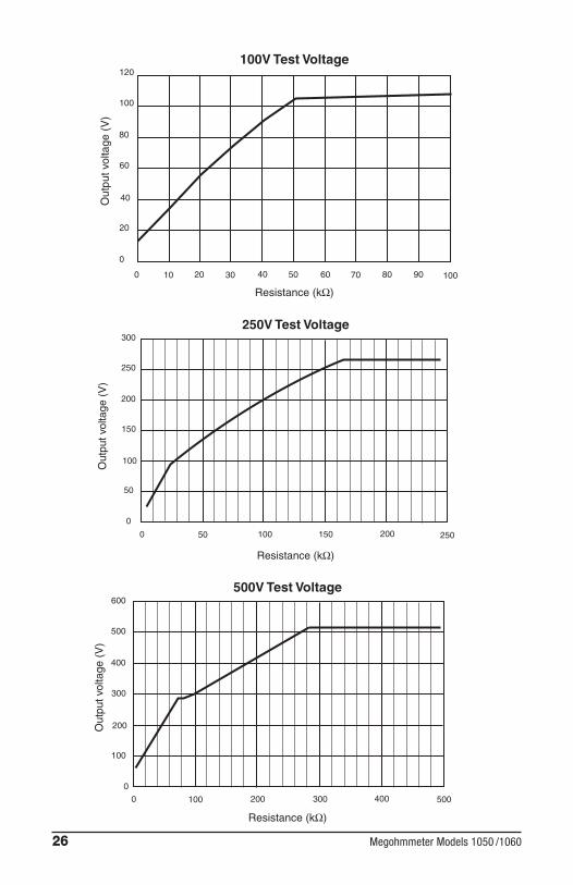
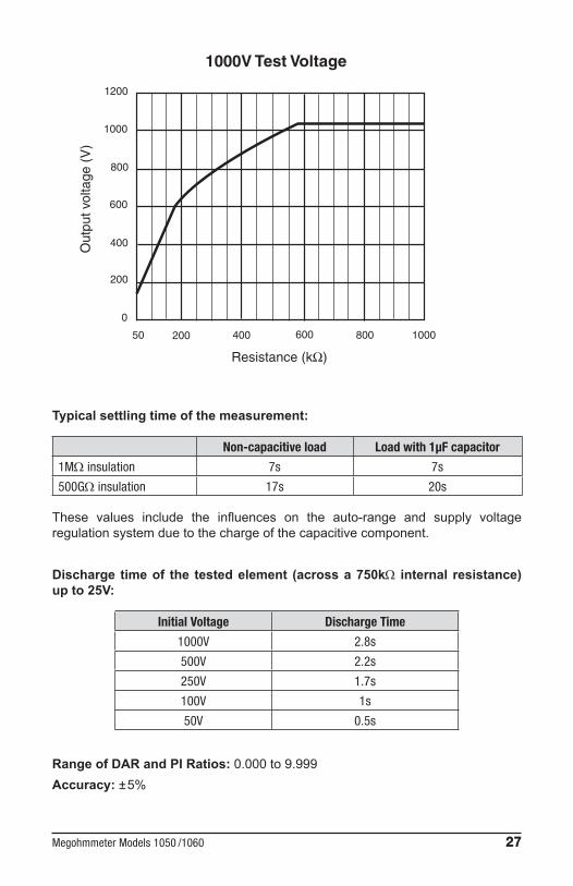
Graphs showing the typical changes in test voltage as a function of the load:
0
0 10 20 30 40 50 60 70 80 90 100
10
20
30
40
50
60
Out
put v
olta
ge (
V)
Resistance (kΩ)
50V Test Voltage
26 Megohmmeter Models 1050 /1060
0
20
40
60
80
100
120
Out
put v
olta
ge (
V)
0 10 20 30 40 50 60 70 80 90 100
Resistance (kΩ)
100V Test Voltage
0
50
100
150
200
250
300
Out
put v
olta
ge (
V)
0 50 100 150 200 250
Resistance (kΩ)
250V Test Voltage
0
100
200
300
400
500
600
Out
put v
olta
ge (
V)
0 100 200 300 400 500
Resistance (kΩ)
500V Test Voltage
Megohmmeter Models 1050 /1060 27
0
50 200 400 600 800 1000
200
400
600
800
1000
1200O
utpu
t vol
tage
(V
)
Resistance (kΩ)
1000V Test Voltage
Typical settling time of the measurement:
Non-capacitive load Load with 1µF capacitor
1MΩ insulation 7s 7s
500GΩ insulation 17s 20s
These values include the influences on the auto-range and supply voltageregulationsystemduetothechargeofthecapacitivecomponent.
Discharge time of the tested element (across a 750kΩ internal resistance) up to 25V:
Initial Voltage Discharge Time
1000V 2.8s
500V 2.2s
250V 1.7s
100V 1s
50V 0.5s
Range of DAR and PI Ratios: 0.000 to 9.999Accuracy: ±5%

28 Megohmmeter Models 1050 /1060
3.4 ContinuityMethod:Voltage-currentmethodaccordingtoEN61557-4(ed.02/97)
Open-circuit Voltage: 12.4VDCmax(<15Vwithexternalsupply)
Short-circuit Current:>200mADC
Maximum Voltage Surge:1200VAC/DCfor10secondsbetweenthe“+”and“-”terminals660VAC/DCbetweenthe“G”and“-”or“G”and“+”terminals
Test Lead Compensation:R∆ismeasuredforthetestleadsinshort-circuitwhenintheSET-UPmenu(see§2.5.7),thisvalueisstoredandsubtractedfromallcontinuitymeasure-ments.Thecompensationislimitedto5Ω.Rdisplayed=Rmeasured-R∆
Continuity Measurement Range: 0.01 to 39.99Ω
Resolution: 0.01Ω
Operating Current:>200mAfrom0.01to20.00Ωand>140mAfrom20.01to39.99Ω
Accuracy: ±3% R ± 4cts
Maximum Inductive Load:5hrswithoutdamagetotheinstrument
Maximum Serial Mode Voltage:3VAC/DC;measurementisprohibitedabovethisvalue
3.5 ResistanceMethod: Voltage-currentmeasurement
Open-circuit Voltage:Max.12.4VDC(<15Vwithexternalsupply)
Short-circuit Current:<6mADC
Max. Voltage Surge:1200VAC/DCfor10secondsbetweenthe“+”and“-”terminals660VAC/DCbetweenthe“G”and“-”or“G”and“+”terminals
Max Serial Mode Voltage:3VAC/DC;measurementisprohibitedabovethisvalue
Megohmmeter Models 1050 /1060 29
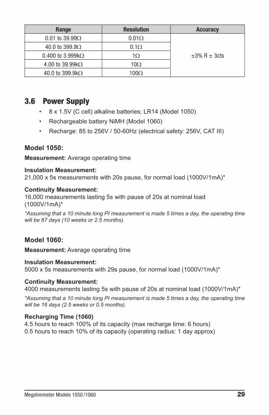
Range Resolution Accuracy0.01 to 39.99Ω 0.01Ω
±3% R ± 3cts40.0 to 399.9Ω 0.1Ω
0.400 to 3.999kΩ 1Ω4.00 to 39.99kΩ 10Ω40.0 to 399.9kΩ 100Ω
3.6 Power Supply• 8x1.5V(Ccell)alkalinebatteries;LR14(Model1050)• RechargeablebatteryNiMH(Model1060)• Recharge:85to256V/50-60Hz(electricalsafety:256V,CATIII)
Model 1050:Measurement: Averageoperatingtime
Insulation Measurement:21,000x5smeasurementswith20spause,fornormalload(1000V/1mA)*
Continuity Measurement:16,000measurementslasting5swithpauseof20satnominalload(1000V/1mA)**Assuming that a 10 minute long PI measurement is made 5 times a day, the operating timewill be 67 days (10 weeks or 2.5 months).
Model 1060:Measurement:Averageoperatingtime
Insulation Measurement:5000x5smeasurementswith29spause,fornormalload(1000V/1mA)*
Continuity Measurement:4000measurementslasting5swithpauseof20satnominalload(1000V/1mA)**Assuming that a 10 minute long PI measurement is made 5 times a day, the operating timewill be 16 days (2.5 weeks or 0.5 months).
Recharging Time (1060)4.5hourstoreach100%ofitscapacity(maxrechargetime:6hours)0.5hourstoreach10%ofitscapacity(operatingradius:1dayapprox)
30 Megohmmeter Models 1050 /1060
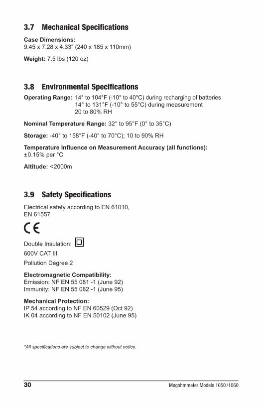
3.7 Mechanical SpecificationsCase Dimensions:9.45x7.28x4.33"(240x185x110mm)
Weight:7.5lbs(120oz)
3.8 Environmental SpecificationsOperating Range:14°to104°F(-10°to40°C)duringrechargingofbatteries
14°to131°F(-10°to55°C)duringmeasurement20 to 80% RH
Nominal Temperature Range: 32°to95°F(0°to35°C)
Storage:-40°to158°F(-40°to70°C);10to90%RH
Temperature Influence on Measurement Accuracy (all functions):±0.15%per°C
Altitude:<2000m
3.9 Safety SpecificationsElectricalsafetyaccordingtoEN61010,EN61557
DoubleInsulation:600V CATIIIPollutionDegree2
Electromagnetic Compatibility:Emission:NFEN55081-1(June92)Immunity:NFEN55082-1(June95)
Mechanical Protection:IP54accordingtoNFEN60529(Oct92)IK04accordingtoNFEN50102(June95)
*All specifications are subject to change without notice.

Megohmmeter Models 1050 /1060 31
CHAPTER 4
OPERATION
NOTE: Charge the instrument fully before use (Model 1060). Measurements cannot be performed during battery charging.
4.1 Measurement Procedure• Start the instrumentbyselecting thecorrespondingposition (MΩ,40Ω
or 400kΩ) with the selector switch.All the segments on the LCDscreenaredisplayed,thenthebattery(orrechargeablebattery)voltageisdisplayed.
• Connect the leads to the “+” and “-” terminals and the points ofmeasurement.
• The input voltage is constantlymeasured and displayed on the smalldisplay.Ifanexternalvoltageispresentthatisgreaterthanthethresholdsdescribedin§4.2,4.3and4.4,thenmeasurementisprohibited.
• PresstheSTART/STOPbuttontostartthemeasurement.• Press START/STOP again to stop the measurement. The last result
remains on the display until the next measurement is started, or theselectorswitchisturned.
WARNING: If a voltage >25VAC or 35VDC is detected during measurements, the instrument indicates this voltage on the small display, the warning symbol flashes and the measurement is stopped.
Note:Thereareseveralspecialfunctionsthatcanbeused(see§2.5).
4.2 Insulation Measurement (see§2.6.2)Thisfunctionallowstheinstrumenttomeasureinsulationresistancefrom1kΩ to 40GΩatatestvoltageof50V,100V,250Vandupto1TΩ at 500V and 1000V.
• Use the rotaryswitch toselect the required testvoltage (MΩ-50V,orMΩ-100V,orMΩ-500V,orMΩ-1000V).
• Connecttheinstrumenttotheinsulatortobetested. • StartthemeasurementusingtheSTART/STOPbuttonandreadtheresults.
WARNING: If the voltage present exceeds 8V for MΩ-50V, 16V for MΩ-100V, or 25V at all the other test voltages, then measurement is prohibited.
ScrollthroughtheresultsonthemaindisplaywiththeR-DAR-PIbutton,oronthesmalldisplaywiththeV/TIMEbutton.Use R(t)whencarryingouta ‘time-controlled test’ toscroll through the intervalmeasurementvaluessavedatthesamplingratespecifiedinSET-UP.

32 Megohmmeter Models 1050 /1060
These values are available until anothermeasurement is taken or the selectorswitchisturned.When measuring high levels of insulation(>1GΩ),itisadvisedthattheguardterminalbeusedtoeliminatetheinfluenceofsurfaceleakagecurrents.Theguardisconnectedbetweenthetwomeasurementcontactpoints,andthesurfacesus-ceptibletosurfacecurrents,(e.g.dusty,dampcableortransformerinsulation).Inthiscase,alligatorclipsarepreferabletotest-probesheldinthehand.As soonas insulationmeasurement is stopped, the test circuit is automaticallydischargedusingtheinstrument’sinternalresistance.
4.3 Continuity Measurement (see§2.6.3)Themeasurementcurrentis>200mAfrom0Ω to 20Ωand>140mAfrom20Ω to 40Ωinthisfunction.Thismeasurementserves to test the low resistance.Themeasurement rangesincreaseautomaticallyupto40Ωwithamaximumresolutionof0.01Ω.
• Selectthe40Ωpositionwithrotaryswitch.• Connecttheinstrumenttothetestobject.• Ifthevoltagepresentis>3V,thenmeasurementisprohibited.• Startthemeasurementandreadtheresults.
NOTE:Itispossibletocompensatefortheleadresistance(see§2.5.10)
NOTE: The R-DAR-PI and V/TIME buttons are not active for this function. There is no automatic polarity change in continuity measurement.
4.4 Resistance Measurement (see§2.6.3)Themeasurement current is limited to 6mA in this function.Themeasurementrangesincreaseautomaticallyupto400kΩwithmaximumresolutionof0.01Ω.
• Select 400kΩpositionwiththerotaryswitch.• Connecttheinstrumenttothetestobject.• Ifthevoltagepresentis>3V,thenmeasurementisprohibited.• Startthemeasurementandreadtheresults.
Duringmeasurement,thepotentialdifferenceattheinputisindicatedonthesmalldisplay(usefulformeasurementofmulti-junctioncomponents:thyristors,highvolt-agediodes,etc).Theopencircuitvoltageisequaltothevoltageoftheinstrument’sbattery.
NOTE: The R-DAR-PI and V/TIME buttons are not active for this function.
4.5 Capacitance MeasurementCapacitancemeasurementisautomaticallycarriedoutduringinsulationmeasure-ment.Itisdisplayedafterthemeasurementisstoppedandthecircuitisdischarged,usingtheR-DAR-PI button.
Megohmmeter Models 1050 /1060 33
CHAPTER 5
MEMORY / RS-232 (Model 1060)
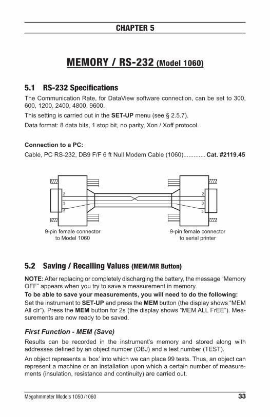
5.1 RS-232 SpecificationsTheCommunicationRate,forDataViewsoftwareconnection,canbesetto300,600,1200,2400,4800,9600.ThissettingiscarriedoutintheSET-UPmenu(see§2.5.7).Dataformat:8databits,1stopbit,noparity,Xon/Xoffprotocol.
Connection to a PC:Cable,PCRS-232,DB9F/F6ftNullModemCable(1060)............. Cat. #2119.45
2 2
3 3
5 5
9-pin female connectorto Model 1060
9-pin female connectorto serial printer
5.2 Saving / Recalling Values (MEM/MR Button)
NOTE:Afterreplacingorcompletelydischargingthebattery,themessage“MemoryOFF”appearswhenyoutrytosaveameasurementinmemory.To be able to save your measurements, you will need to do the following:SettheinstrumenttoSET-UPandpresstheMEMbutton(thedisplayshows“MEMAllclr”).PresstheMEMbuttonfor2s(thedisplayshows“MEMALLFrEE”).Mea-surementsarenowreadytobesaved.
First Function - MEM (Save)Results can be recorded in the instrument’s memory and stored along withaddressesdefinedbyanobjectnumber(OBJ)andatestnumber(TEST).Anobjectrepresentsa‘box’intowhichwecanplace99tests.Thus,anobjectcanrepresentamachineoraninstallationuponwhichacertainnumberofmeasure-ments(insulation,resistanceandcontinuity)arecarriedout.
34 Megohmmeter Models 1050 /1060
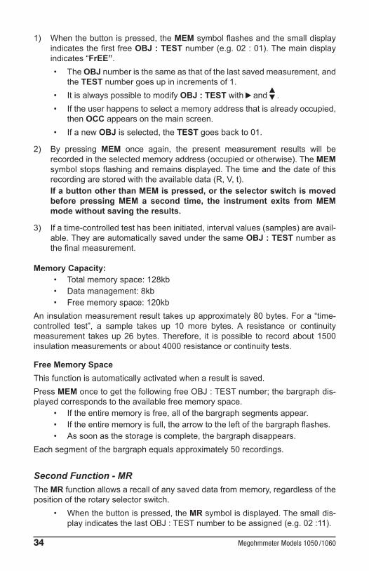
1) Whenthebuttonispressed,theMEMsymbolflashesandthesmalldisplayindicatesthefirstfreeOBJ : TESTnumber(e.g.02:01).Themaindisplayindicates“FrEE”.• TheOBJnumberisthesameasthatofthelastsavedmeasurement,and
theTESTnumbergoesupinincrementsof1.• ItisalwayspossibletomodifyOBJ : TESTwith and .• Iftheuserhappenstoselectamemoryaddressthatisalreadyoccupied,
thenOCCappearsonthemainscreen.• IfanewOBJisselected,theTESTgoesbackto01.
2) By pressing MEM once again, the present measurement results will berecordedintheselectedmemoryaddress(occupiedorotherwise).TheMEM symbolstopsflashingandremainsdisplayed.Thetimeandthedateofthisrecordingarestoredwiththeavailabledata(R,V,t).If a button other than MEM is pressed, or the selector switch is moved before pressing MEM a second time, the instrument exits from MEM mode without saving the results.
3) Ifatime-controlledtesthasbeeninitiated,intervalvalues(samples)areavail-able.TheyareautomaticallysavedunderthesameOBJ : TESTnumberasthefinalmeasurement.
Memory Capacity: • Totalmemoryspace:128kb• Datamanagement:8kb• Freememoryspace:120kb
Aninsulationmeasurementresulttakesupapproximately80bytes.Fora“time-controlled test”, a sample takes up 10 more bytes. A resistance or continuitymeasurement takesup26bytes.Therefore, it ispossible to recordabout1500insulationmeasurementsorabout4000resistanceorcontinuitytests.
Free Memory SpaceThisfunctionisautomaticallyactivatedwhenaresultissaved.PressMEMoncetogetthefollowingfreeOBJ:TESTnumber;thebargraphdis-playedcorrespondstotheavailablefreememoryspace.
• Iftheentirememoryisfree,allofthebargraphsegmentsappear.• Iftheentirememoryisfull,thearrowtotheleftofthebargraphflashes.• Assoonasthestorageiscomplete,thebargraphdisappears.
Eachsegmentofthebargraphequalsapproximately50recordings.
Second Function - MRTheMRfunctionallowsarecallofanysaveddatafrommemory,regardlessofthepositionoftherotaryselectorswitch.
• Whenthebuttonispressed,theMRsymbolisdisplayed.Thesmalldis-playindicatesthelastOBJ:TESTnumbertobeassigned(e.g.02:11).

Megohmmeter Models 1050 /1060 35
• 02“11”flashesoppositetheTESTsymbol.Usethe and buttonstoselectthedesiredOBJ:TESTnumber.
• If a newOBJ is selected, TEST is automatically set to themaximumstorednumber.At thisstage it ispossible to reviewtheentirememorywiththe and buttons,sincethemeasurementvaluescorrespondingtotheselectedOBJ:TESTnumberaredisplayedonthemaindisplay.UsetheR-DAR-PIbuttontoscrollthroughthem.
• The V/TIMEbuttongivesaccesstothedate/ time/V/OBJ-TESTnumberforeachresult.
• If the recordingselectedby theOBJ :TESTnumbercorresponds toatime-controlled test, theR(t) values can be accessed by pressing theR(t)button.Thesmalldisplaychangesandindicatesmin:sec(timeof1stsample)andthesymbol flashesonthescreen.Youcanscrollthroughtheothersampleswiththe button.
To exit from R(t) mode and return to the normalmemory recallmode (OBJ :TEST), pressR(t) or R-DAR-PIagain.To exit the MR function,press theMR buttononceagainorturntheselectorswitch.
5.3 Printing Measured Values (PRINT/PRINT MEM Button - Model 1060)
NOTE: AEMCsuggeststhatprintingbeperformedthroughtheDataViewsoftwarevs.thePRINTButton.
However,ifyouuseaserialprinter,choosetheappropriatecommunicationspeed(communicationrate)intheSET-UPmenu,between300and9600,thenprogramtheprintertotheformatrunbytheinstrument(see§5.1).Ifyouareusingaparallelprinter,youshouldsetthecommunicationrateto“Paral-lel” wheninSET-UPandusetheoptionalserial-to-paralleladapter.Therearetwoprintingmodespossible:
• Instantaneousprintingofmeasurement(PRINT)• Printingofrecordeddata(PRINTmemory)
If the data transmission to the printer is successful, the COM symbol flashes once on the screen. If a problem has occurred, the COM symbol remains on the LCD screen without flashing.
36 Megohmmeter Models 1050 /1060
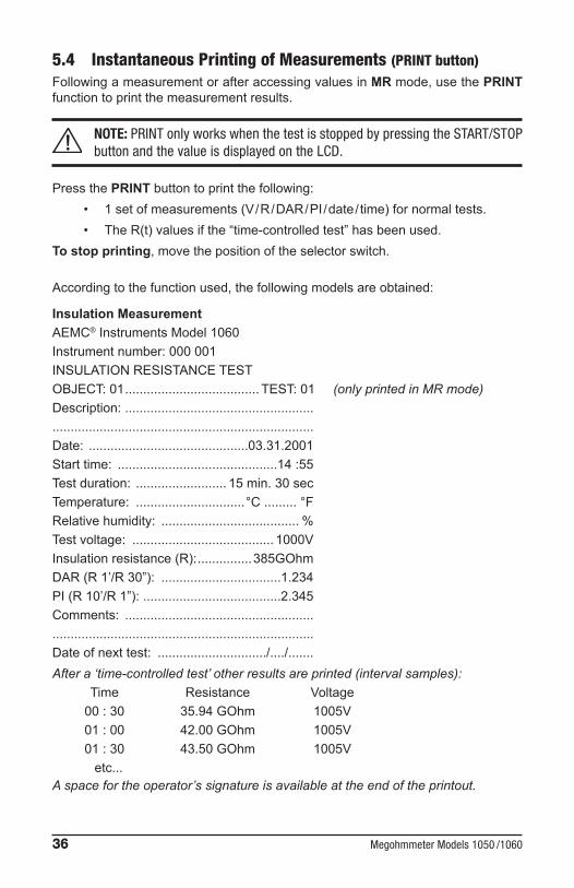
5.4 Instantaneous Printing of Measurements (PRINT button)FollowingameasurementorafteraccessingvaluesinMRmode,usethePRINT functiontoprintthemeasurementresults.
NOTE: PRINT only works when the test is stopped by pressing the START/STOP button and the value is displayed on the LCD.
PressthePRINTbuttontoprintthefollowing:• 1setofmeasurements(V/R/DAR/PI/date/ time)fornormaltests.• TheR(t)valuesifthe“time-controlledtest”hasbeenused.
To stop printing,movethepositionoftheselectorswitch.
Accordingtothefunctionused,thefollowingmodelsareobtained:
Insulation MeasurementAEMC®InstrumentsModel1060Instrumentnumber:000001INSULATIONRESISTANCETESTOBJECT:01 .....................................TEST:01(only printed in MR mode)Description:............................................................................................................................Date: ............................................03.31.2001Starttime: ............................................14:55Testduration: ......................... 15 min. 30 secTemperature: ..............................°C.........°FRelativehumidity: ...................................... %Testvoltage: ....................................... 1000VInsulationresistance(R): ...............385GOhmDAR(R1’/R30”): .................................1.234PI(R10’/R1”):......................................2.345Comments: ............................................................................................................................Dateofnexttest: ............................../..../.......After a ‘time-controlled test’ other results are printed (interval samples):
Time Resistance Voltage00:30 35.94GOhm 1005V01:00 42.00GOhm 1005V01:30 43.50GOhm 1005V etc...
A space for the operator’s signature is available at the end of the printout.

Megohmmeter Models 1050 /1060 37
Continuity or Resistance MeasurementAEMC®InstrumentsModel1060Instrumentnumber:000001CONTINUITYTESTorRESISTANCETESTOBJECT:01 ...................................TEST:01(onlyprintedinMRmode)Description:.............................................................................................................................Date: ............................................03.31.2001Starttime: ...........................................14:55Testcurrent: .................................... >200mALeadcompensation: ............................0.12ΩPotentialdifference: ............................... 0.9VContinuityorResistance:.....................0.45ΩComments: .....................................................................................................................................................................................................Dateofnexttest: .............................../..../.......A space for the operator’s signature is available at the end of the printout.
5.5 Printing Data in Memory (PRINT MEM button)Printsoutthecontentsoftheinstrument’sread-writememory.Thesmalldisplayindicates01:01fortheOBJ:TESTnumber(startingaddressofprinting).Themaindisplayindicatesthelastrecordinginmemory(theendaddressofprint-ing).e.g.12:06.
01 flashesopposite theOBJposition, theusual selectionprocedure should beused( and buttons)inordertodefinethestart/endaddressesoftheprintout.
• To exit without printing,alterthepositionoftheselectorswitch.• To proceed with printing,pressthePRINTbuttononcemore.• To stop printing,alterthepositionoftheselectorswitch.
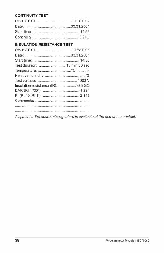
Onlythemainresultsareprintedout.Example:AEMC®InstrumentsModel1060Instrumentnumber:000001CONTINUITY TESTOBJECT:01 .....................................TEST:01Date: ............................................03.31.2001Starttime: .............................................14:55Continuity:............................................0.45Ω
38 Megohmmeter Models 1050 /1060
CONTINUITY TESTOBJECT:01 .....................................TEST:02Date: ............................................03.31.2001Starttime: .............................................14:55Continuity:............................................0.91Ω
INSULATION RESISTANCE TEST OBJECT:01 .....................................TEST:03Date: ............................................03.31.2001Starttime: .............................................14:55Testduration: .......................... 15 min 30 secTemperature: ................................°C.........°FRelativehumidity: ....................................... %Testvoltage: ...................................... 1000 VInsulationresistance(IR): .................385 GΩDAR(RI1’/30”): ....................................1.234PI(RI10’/RI1’): ....................................2.345Comments: .....................................................................................................................................................................................................A space for the operator’s signature is available at the end of the printout.
Megohmmeter Models 1050 /1060 39
CHAPTER 6
APPLICATION EXAMPLES
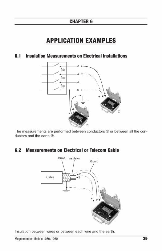
6.1 Insulation Measurements on Electrical Installations
L1
L2
L3
N
-
+-
+
Themeasurementsareperformedbetweenconductorsorbetweenallthecon-ductorsandtheearth.
6.2 Measurements on Electrical or Telecom Cable
+ - G
a
bCable
Braid InsulatorGuard
Insulationbetweenwiresorbetweeneachwireandtheearth.

40 Megohmmeter Models 1050 /1060
6.3 Insulation Measurements on Motors
+ -
Motor
+ -+ -
Motor coils

Megohmmeter Models 1050 /1060 41
CHAPTER 7
USING DATAVIEW®
7.1 Installing DataView®
DO NOT CONNECT THE INSTRUMENT TO THE PC BEFORE INSTALLING THE SOFTWARE AND DRIVERS.
NOTE:When installing, the user must haveAdministrative access rightsduring the installation.Theusers access rights canbe changedafter theinstallationiscomplete.
1. Insert theDataView thumb drive into an availableUSB port on your com-puter. IfAutorun is enabled, anAutoPlaywindowappears on your screen.Click“Openfoldertoviewfiles”todisplaytheDataViewfolder.IfAutorunisnotenabledorallowed,useWindowsExplorertolocateandopentheUSBdrivelabeled“DataView.”
2. WhentheDataViewfolderisopen,findthefileSetup.exelocatedintherootdirectoryoftheUSBdrive,anddouble-clickittoruntheinstallationprogram.
3. TheDataViewsetupscreenappears.

42 Megohmmeter Models 1050 /1060
In theupper left cornerof the screen, choose the languageversionof theSetupinterface.(AllSetupscreensanddialogswillimmediatelyappearintheselectedlanguage.)
Inthelowerleftcorneraretheavailableinstallationoptions.InadditiontotheDataViewsoftware,youcanselect“AdobeReader.”ThislinkstotheAdobewebsitewhereyoucandownloadthelatestversionofReader.ThisprogramisrequiredtoviewDataView.pdfdocuments.TheoptionFirmwareUpgradeslinksto thewebsitewhereyoucancheckfornewfirmwareupdatesfor theinstrument.Finally,UserManualsdisplaysalistof.pdffilescontainedintheUSBdrive thataccompaniesDataView. (DataViewalsocomeswithaHelpsystemthatisinstalledwiththeprogramfiles.)
ToinstallDataView,selectDataViewintheOptionslistandclickInstall.
4. SelectthelanguageversionofDataViewyouwanttoinstall(English,French,orSpanish) thenclickNext. (Bydefault, the languageselected instep3 ishighlighted.)
5. Youarenowpromptedtoselectthesoftwareyouwanttoinstall.EachAEMCproductfamilyhasitsownspeciallydesignedControlPanel.Ifyouareper-formingaCompleteinstall,bydefaultallavailableControlPanelsareselected(acheckmarknexttotheControlPanelindicatesitisselected).ControlPan-elstakeupdiskspaceonthecomputer;sounlessyouhaveothertypesofAEMC instruments,we recommend that youselectMegohmmeterandde-selecttherest.YoushouldalsochecktheoptionDataViewCore,whichisarequirementifyouplantocreateDataViewreports.
After you finish selecting and deselectingControl Panels and/orDataViewCore,clickNext.

Megohmmeter Models 1050 /1060 43
6. TheSetupprogramnowinformsyouthatitisreadytoinstallDataView.Ifyouwanttoreviewanyofyourpreviousselections,clickthePreviousbuttontoreturntoearlierscreens.Otherwise,clickInstalltobegininstallation.
7. TheInstallShieldprograminstallstheselectedsoftware.Ifanearlierversionofthesoftwareisalreadyinstalledonyourcomputer,foreachselectedpro-gramtheInstallShieldprogramwill:
(a)Askyoutoconfirmtheinstallationoftheprogram.ClickNext.
(b)Displayastatusbarindicatingtheprogressoftheinstallation.
(c)Informyouwhentheprogramisinstalled.
ClickFinishtoinstallthenextselectedprogram.
Ifthesoftwareisnotinstalled(oriftheinstalledsoftwareisthesameversionastheselectedsoftware),thesoftwareisinstalledwithoutrequestingconfirmation. Whenallprogramsare installed,amessageappears informingyouof this.ClickFinishtoreturntotheSetupscreen
8. You cannowselect additionalSetupoptions to install (see step3 above).Whenfinished,clickExit.
9. TheDataViewfoldernowappearsonyourcomputerdesktop,withinwhichistheMegohmmeter iconandtheicon(s)foranyotherControlPanel(s)youhaveinstalled.
7.2 Megohmmeter Control PanelClicking the DataView icon in the DataView folder on your desktop opens thecoreDataViewprogram.ClickingtheMegohmmeterControlPaneliconopenstheMegohmmeterControlPanel.
Ingeneral,coreDataViewfeaturesareforcreating,viewing,editing,andstoringDataViewreports;whiletheControlPanelisforconnectingto,configuring,view-ingmeasurementson,anddownloadingdatafromtheinstrument.YoucanaccessallDataViewfeaturesthrougheithertheDataViewiconortheControlPanelicon.Foruserswhointeractwithmegohmmeterinstruments,werecommendprimarilyusingtheControlPanel.However,therearesituationswhereusingthecoreData-Viewiconmaybemoreconvenientforsomeusers,suchaswhenviewingmultiplearchivedreportsfromdifferentAEMCproductfamilies.
ForfurtherinformationaboutusingtheMegohmmeterControlPanel,consulttheHelpsystemthatcomeswiththeproduct.AccessthisHelpbyclickingtheoptionHelpintheControlPanel’smenubaratthetopofthescreen.
44 Megohmmeter Models 1050 /1060
CHAPTER 8
MAINTENANCE
Useonlyfactoryspecifiedreplacementparts.AEMC®willnotbeheldresponsibleforanyaccident,incident,ormalfunctionfollowingarepairdoneotherthanbyitsservicecenterorbyanapprovedrepaircenter.
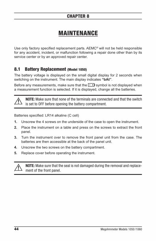
8.1 Battery Replacement (Model 1050)
Thebatteryvoltageisdisplayedonthesmalldigitaldisplayfor2secondswhenswitchingontheinstrument.Themaindisplayindicates“bAt”. Beforeanymeasurements,makesurethatthe symbolisnotdisplayedwhenameasurementfunctionisselected.Ifitisdisplayed,changeallthebatteries.
NOTE: Make sure that none of the terminals are connected and that the switch is set to OFF before opening the battery compartment.
Batteriesspecified:LR14alkaline(Ccell)
1. Unscrewthe4screwsontheundersideofthecasetoopentheinstrument.2. Placetheinstrumentonatableandpressonthescrewstoextractthefront
panel.3. Turnthe instrumentover toremovethefrontpanelunit fromthecase.The
batteriesarethenaccessibleatthebackofthepanelunit.4. Unscrewthetwoscrewsonthebatterycompartment.5. Replacecoverbeforeoperatingtheinstrument.
NOTE: Make sure that the seal is not damaged during the removal and replace-ment of the front panel.

Megohmmeter Models 1050 /1060 45
8.2 Recharging the Battery (Model 1060)
If the symbol isflashing,thenit isnecessarytorechargethebattery.Con-necttheinstrumenttothe120VACpowercordviatheconnector,chargingstartsautomatically:
• bAt on thesmall displayandCHrG on themaindisplay, signifies fastcharginginprogress.
• bAtonthesmalldisplayandCHrGflashingonthemaindisplay,signifiesslowcharging(startsoffwithfastcharge,temperatureconditionspermitting).
• bAt on thesmall displayandFULL on themaindisplay, signifies thatchargingisover.
Iftheinstrumentisstartedupandthebatteryvoltageis>8V,thenthenormaluseofthedeviceispermitted.
NOTE: The battery should be changed by an authorized repair facility recog-nized by AEMC® Instruments.
Changing the battery causes data to be lost from the memory.
PresstheMEM/MRbutton.“OFF” isdisplayed.ProceedwithatotalclearingofmemoryinSET-UP(see§2.5.7)sotheMEM/MRfunctionscanbeusedagain.
8.3 Fuse ReplacementIfFUS HI or FUSE -G-flashesontheLCDwhenturningthe instrumentON,orduringcontinuitymeasurement,thenitisimperativethatthecorrespondingfusesbechanged,takingallthenecessaryprecautionswhenopeninguptheinstrument(see§8.1foropeningprocedure).
NOTE: Make sure that none of the terminals are connected and that the selec-tor switch is set to OFF before opening up the case.
Usingonlythetypesoffusesshownonthestickerinbatterycompartment:• “+”terminalfuseF1(FUSHI): F2.5Afastfuse-1.2kV-8x50mm-15kA• “G”terminalfuseF2(FUSG): F0.1Afastfuse-660V-6.3x32mm-20kA

46 Megohmmeter Models 1050 /1060
8.4 Cleaning
Disconnect the instrument from any source of electricity. Useasoftclothlightlydampenedwithsoapywater.Rinsewithawetclothandthendrywithadrycloth.Donotusealcohol,solventsorhydrocarbons.
8.5 StorageIftheinstrumentisnotusedforanextendedtimeperiod(longerthantwomonths),removethebatteryandstoreseparately(Model1050).
Megohmmeter Models 1050 /1060 47
Repair and CalibrationTo ensure that your instrument meets factory specifications, we recommendthat itbescheduledbacktoourfactoryServiceCenteratone-year intervalsforrecalibration,orasrequiredbyotherstandardsorinternalprocedures.
For instrument repair and calibration:YoumustcontactourServiceCenterforaCustomerServiceAuthorizationNumber(CSA#). This will ensure that when your instrument arrives, it will be trackedandprocessedpromptly.Pleasewrite theCSA#on theoutsideof theshippingcontainer.Iftheinstrumentisreturnedforcalibration,weneedtoknowifyouwantastandardcalibration,oracalibration traceable toN.I.S.T. (Includescalibrationcertificateplusrecordedcalibrationdata).
Ship To: ChauvinArnoux®,Inc.d.b.a.AEMC®Instruments 15FaradayDrive Dover,NH03820USA Phone: (800)945-2362(Ext.360) (603)749-6434(Ext.360) Fax: (603)742-2346or(603)749-6309 E-mail: [email protected]
(Orcontactyourauthorizeddistributor)
Costs for repair, standard calibration, and calibration traceable to N.I.S.T. areavailable.
NOTE: You must obtain a CSA# before returning any instrument.
Technical and Sales Assistance
Ifyouareexperiencinganytechnicalproblems,orrequireanyassistancewiththeproperoperationorapplicationofyour instrument,pleasecall, faxore-mailourtechnicalsupportteam:
Contact: ChauvinArnoux®,Inc.d.b.a.AEMC®Instruments Phone: (800)945-2362(Ext.351) (603)749-6434(Ext.351) Fax: (603)742-2346 E-mail: [email protected]
48 Megohmmeter Models 1050 /1060
Limited WarrantyTheMegohmmeterModel1050/1060 iswarranted to theowner foraperiodoftwoyearsfromthedateoforiginalpurchaseagainstdefectsinmanufacture.ThislimitedwarrantyisgivenbyAEMC®Instruments,notbythedistributorfromwhomitwaspurchased.Thiswarrantyisvoidiftheunithasbeentamperedwith,abusedorifthedefectisrelatedtoservicenotperformedbyAEMC®Instruments.
Full warranty coverage and product registration is available on our website at www.aemc.com/warranty.html.
Please print the online Warranty Coverage Information for your records.
What AEMC® Instruments will do:Ifamalfunctionoccurswithinthewarrantyperiod,youmayreturntheinstrumenttousforrepair,providedwehaveyourwarrantyregistrationinformationonfileoraproofofpurchase.AEMC® Instrumentswill,at itsoption,repairorreplacethefaultymaterial.
REGISTER ONLINE AT: www.aemc.com
Warranty Repairs
What you must do to return an Instrument for Warranty Repair: First,requestaCustomerServiceAuthorizationNumber(CSA#)byphoneorbyfaxfromourServiceDepartment(seeaddressbelow),thenreturntheinstrumentalongwith thesignedCSAForm.Pleasewrite theCSA#on theoutsideof theshippingcontainer.Returntheinstrument,postageorshipmentpre-paidto:
Ship To: ChauvinArnoux®,Inc.d.b.a.AEMC®Instruments15FaradayDrive•Dover,NH03820USAPhone: (800)945-2362(Ext.360)
(603) 749-6434(Ext.360)Fax: (603)742-2346or(603)749-6309E-mail: [email protected]
Caution: To protect yourself against in-transit loss,we recommend you insureyourreturnedmaterial.
NOTE: You must obtain a CSA# before returning any instrument.

Notes:


02/20
99-MAN100237v38
Chauvin Arnoux®, Inc. d.b.a. AEMC® Instruments15FaradayDrive•Dover,NH03820USA•Phone:(603)749-6434•Fax:(603)742-2346
www.aemc.com