meljun cortes multimedia lecture chapter11 story
TRANSCRIPT
Important Guidelines of
STORY
MELJUN CORTESMELJUN CORTES
Chapter 11Chapter 11
Tracing
Microsoft Expression Design has four different path-drawing tools:B-Spline toolPolyline toolPen toolPaintbrush tool
The B-Spline tool
1.Select the B-Spline tool in the Toolbox 2.Click anywhere in the workspace to set the starting point of the path. 3.Move the pointer and watch the thin gray line as you move the cursor to see how this curve segment will look when you click. Hold down the SHIFT key to constrain the position of the node relative to the previous node.4.Click to place another node. You can hold down the ALT key while you click to place a sharp corner at this point. 5.Repeat steps 3 and 4 until you're ready to end the path. Note that you can remove the last node you added by pressing the DELETE or Backspace key. 6.To end the path (stop drawing), do one of the following:
•To create a closed path, position the cursor on top of the starting point and click. •Double-click at any point to place an ending node. •Press ENTER or ESC to end the path at the last-placed node.
Tip: When you want to create a curve coming out of a straight portion, add an extra node before the curve begins. Otherwise, the curve will affect the straight-line segment.
Polyline tool
1.Select the Polyline tool in the Toolbox. 2.Click anywhere in the workspace to set the starting point of the path.3.Do one of the following:
• Move the cursor, and then click to add another node for a straight-line segment. You can hold down the SHIFT key to constrain the position of the node to 90- or 45-degrees from the previous node.
• Move the pointer, and then click and drag to add a circular arc segment. The point at which you click before dragging determines the tangent of the curve that will be created. This point will not actually be on the curve, but will define the angle between the straight line segment and the arc segment. You can hold down the SHIFT key to constrain the circular arc to 90, 180, or 270 degrees. When you let go of the mouse button, Expression Design adds the appropriate nodes to the path.
4. Repeat step 3 until you're ready to end the path. Note that you can remove the last node you added by pressing the DELETE or Backspace key. 5. To end the path (stop drawing), do one of the following:
• To create a closed path, position the cursor on top of the first node (the starting point) and click.
• Double-click at any point to place an ending node. • Press ENTER or ESC to end the path at the last-placed node.
Tip: Using the Polyline tool to draw straight line segments is easy. You just click, click, and click. However, drawing arcs takes some getting used to. Remember that when you draw an arc the point where you click determines the angle at which the arc attaches to the line, but it has no effect on the actual size of the arc. So, you'll find that you sometimes have more control over the shape of the arc when you click farther away from the previous node (before you start dragging), even if you're trying to create a small arc.
Pen tool
Once you have the Pen tool selected in the Toolbox, you can start creating anchor points by performing one of these actions:
•To create a corner point click anywhere in the workspace. •To create a curve anchor point with visible tangent handles, click and drag. •To create a cusp point with the "in" handle retracted fully and the "out" handle extended, position the cursor by pressing CTRL+ALT while you drag the cursor. •To create a cusp point with the two control handles extended but acting independently of each other, drag the cursor to create in and out handles, and then go back and press the ALT key while dragging the cursor on the out handle you just created.
Tip: You can remove the last anchor point you added by pressing the DELETE or Backspace key.
Paintbrush tool
After you draw a shape using the Paintbrush tool, Expression Design automatically fits a Bezier path to your freehand trail.
After selecting the Paintbrush tool from the Toolbox, you can draw a Bezier path simply by dragging out a shape in the document window. If you want to create a closed path, place the cursor over the starting point of the path and let go of the mouse button when a small white circle appears next to the cursor.Drawing a trail with the Paintbrush tool, and the resulting Bezier path with brush stroke applied
Note: that you can also use the Paintbrush tool as an object-selection tool. Just click (without dragging) any path to select it, or click on an empty area of the page to deselect all objects.
Color
Blending modesYou can affect the look of an object by changing the way that it blends with colors beneath it. When you change an object's blending mode, the fill and stroke colors change, depending on what colors are beneath the object.
Here is a short description of each blending mode.
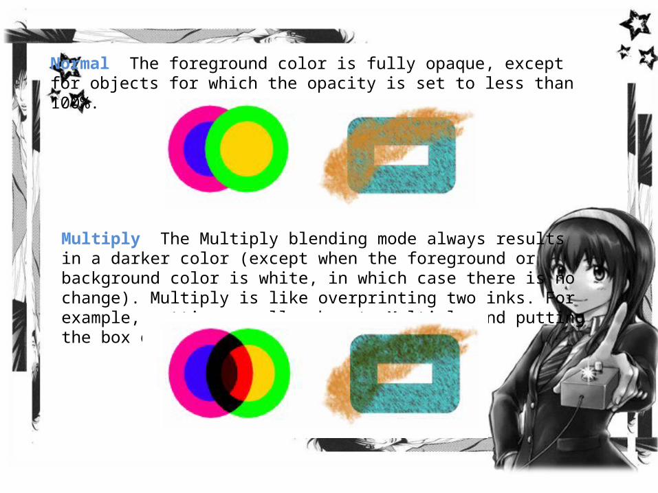
Normal The foreground color is fully opaque, except for objects for which the opacity is set to less than 100%.
Multiply The Multiply blending mode always results in a darker color (except when the foreground or background color is white, in which case there is no change). Multiply is like overprinting two inks. For example, setting a yellow box to Multiply and putting the box over a blue area results in green.
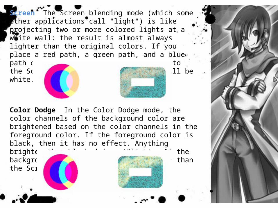
Screen The Screen blending mode (which some other applications call "light") is like projecting two or more colored lights at a white wall: the result is almost always lighter than the original colors. If you place a red path, a green path, and a blue path on top of each other and set them to the Screen blending mode, the result will be white.
Color Dodge In the Color Dodge mode, the color channels of the background color are brightened based on the color channels in the foreground color. If the foreground color is black, then it has no effect. Anything brighter than black dodges ("lightens") the background. The result is often lighter than the Screen blending mode.
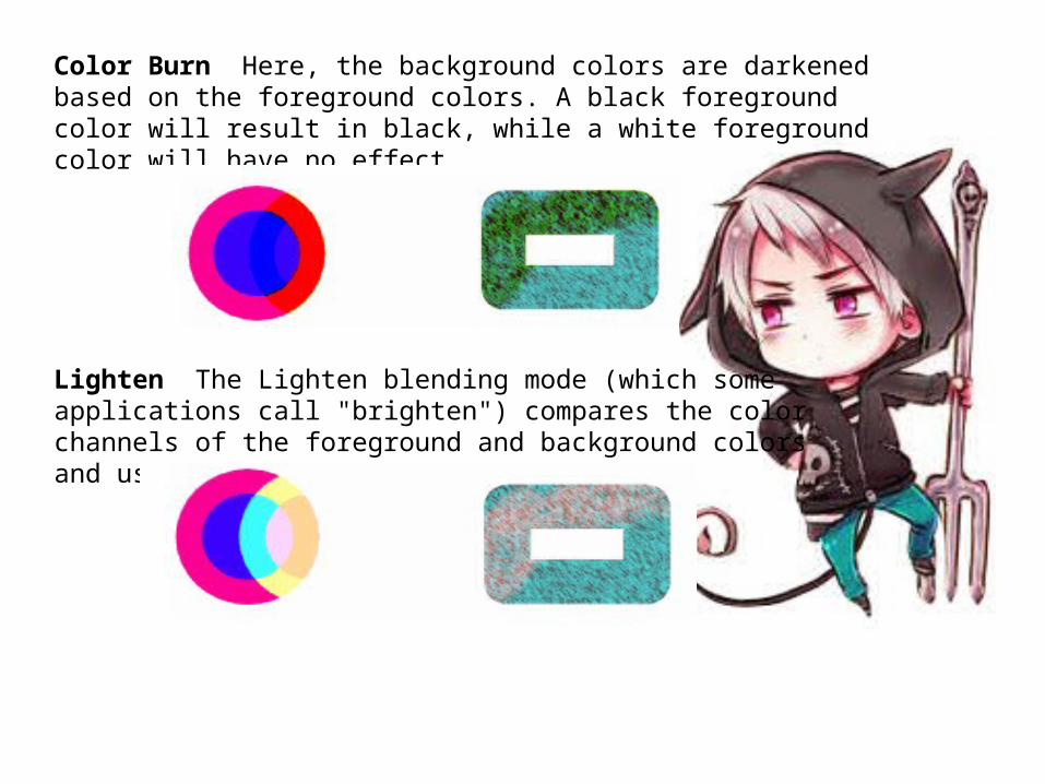
Color Burn Here, the background colors are darkened based on the foreground colors. A black foreground color will result in black, while a white foreground color will have no effect.
Lighten The Lighten blending mode (which some applications call "brighten") compares the color channels of the foreground and background colors and uses the lighter of the two.
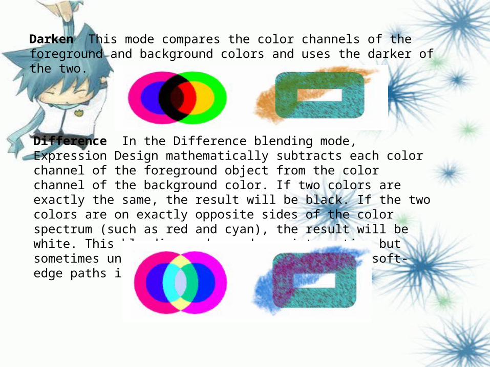
Darken This mode compares the color channels of the foreground and background colors and uses the darker of the two.
Difference In the Difference blending mode, Expression Design mathematically subtracts each color channel of the foreground object from the color channel of the background color. If two colors are exactly the same, the result will be black. If the two colors are on exactly opposite sides of the color spectrum (such as red and cyan), the result will be white. This blending mode produces interesting but sometimes unexpected results, especially with soft-edge paths in bright colors.
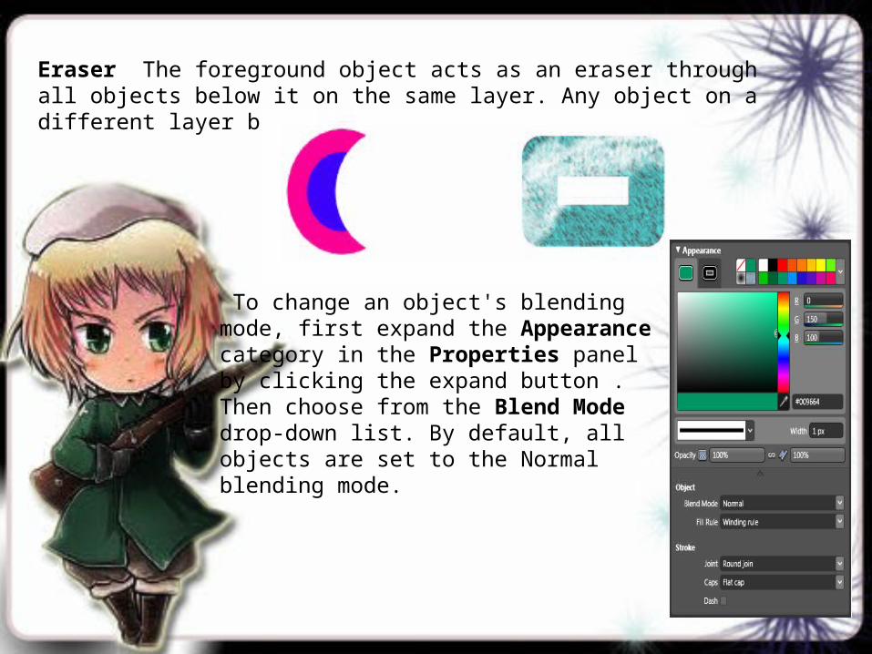
Eraser The foreground object acts as an eraser through all objects below it on the same layer. Any object on a different layer beneath shows through.
To change an object's blending mode, first expand the Appearance category in the Properties panel by clicking the expand button . Then choose from the Blend Mode drop-down list. By default, all objects are set to the Normal blending mode.
Toolbox
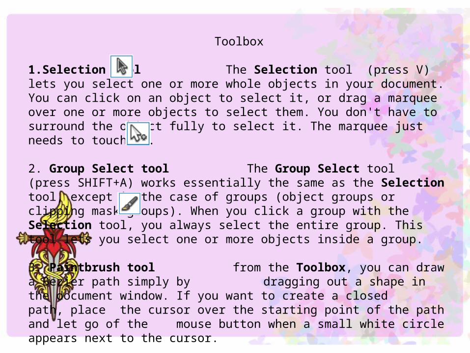
1.Selection tool The Selection tool (press V) lets you select one or more whole objects in your document. You can click on an object to select it, or drag a marquee over one or more objects to select them. You don't have to surround the object fully to select it. The marquee just needs to touch it.
2. Group Select tool The Group Select tool (press SHIFT+A) works essentially the same as the Selection tool, except in the case of groups (object groups or clipping mask groups). When you click a group with the Selection tool, you always select the entire group. This tool lets you select one or more objects inside a group.
3. Paintbrush tool from the Toolbox, you can draw a Bezier path simply by dragging out a shape in the document window. If you want to create a closed path, place the cursor over the starting point of the path and let go of the mouse button when a small white circle appears next to the cursor.
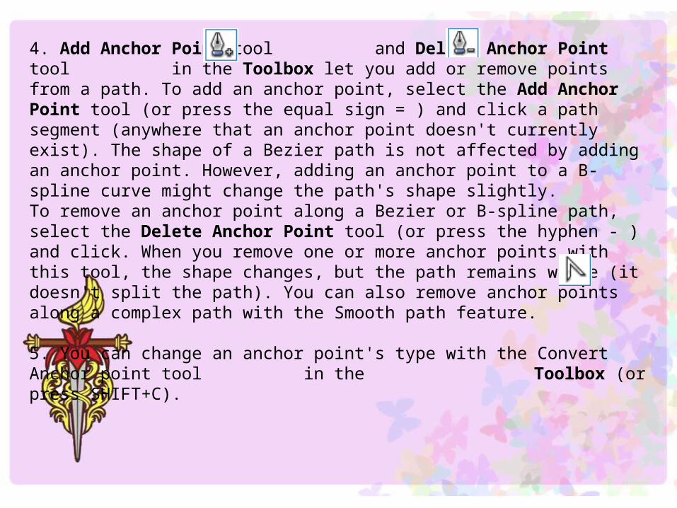
4. Add Anchor Point tool and Delete Anchor Point tool in the Toolbox let you add or remove points from a path. To add an anchor point, select the Add Anchor Point tool (or press the equal sign = ) and click a path segment (anywhere that an anchor point doesn't currently exist). The shape of a Bezier path is not affected by adding an anchor point. However, adding an anchor point to a B-spline curve might change the path's shape slightly.To remove an anchor point along a Bezier or B-spline path, select the Delete Anchor Point tool (or press the hyphen - ) and click. When you remove one or more anchor points with this tool, the shape changes, but the path remains whole (it doesn't split the path). You can also remove anchor points along a complex path with the Smooth path feature.
5. You can change an anchor point's type with the Convert Anchor point tool in the Toolbox (or press SHIFT+C).
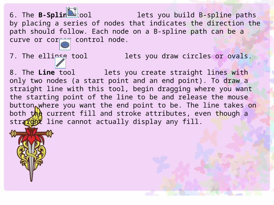
6. The B-Spline tool lets you build B-spline paths by placing a series of nodes that indicates the direction the path should follow. Each node on a B-spline path can be a curve or corner control node.
7. The ellipse tool lets you draw circles or ovals.
8. The Line tool lets you create straight lines with only two nodes (a start point and an end point). To draw a straight line with this tool, begin dragging where you want the starting point of the line to be and release the mouse button where you want the end point to be. The line takes on both the current fill and stroke attributes, even though a straight line cannot actually display any fill.
9. Transform Fill tool and the Transform Fill menu.To transform an image fill or gradient with the Transform Fill tool;A more precise method of transforming an image fill for a selected object is to click on the Transform Fill menu in the Appearance category of the Properties panel. This menu lets you adjust positioning (X and Y offsets), scaling (W and H), Rotation Angle , and Skew Angle .
10. You can split an open path into two separate paths, or split a closed path to become an open path, by selecting the Scissors tool from the Toolbox (or press C) and clicking any point along the path (either a path segment or a node). B-spline paths are automatically converted to Bezier paths when you split them.You can also split a path by selecting one or more anchor points along the path and pressing DELETE. This removes the nodes and their adjacent segments.
11. You can change which node on a path is marked as the starting point by selecting the Start Point tool in the Toolbox and then clicking the node.
12. The Attribute Dropper tool lets you copy the fill, stroke, and effect attributes from one object in your document to another. In effect, this copies all of the formatting you can set in the Properties panel in one movement. To copy these attributes from one object to another, click the fill or stroke area of the first object, then, while you hold down the mouse button, drag the Attribute Dropper tool to the second object. Release the mouse button over the fill or stroke area of the second object. If the second object has no fill or stroke color, then release the mouse button while the tool is over the path itself.
13. All path and shape objects are built from a series of anchor points (also sometimes called "points" or "nodes"). To change an object's shape you often need to select one or more of these points. When you select an object with the Selection tool or Group Select
tool, all the nodes are selected. Expression Design offers two tools for selecting individual nodes: the Direct Selection tool and the Lasso Selection tool . The Lasso Selection tool has all the features of the Direct Selection tool, but offers more flexibility.
14. The Pen tool lets you build Bezier paths by placing a series of anchor points (sometimes called "nodes") and control handles (or "tangent handles"). Each segment on the path consists of the two anchor points on either side of the path segment and the two control handles . Both the lengths and directions of the control handles affect the shape of a Bezier curve.
15. Delete Anchor Point tool in the Toolbox let you add or remove points from a path.
16. The Polyline tool lets you build a Bezier path made of segments that are either straight lines or circular arcs. This is useful because it is difficult to draw a circular arc in the middle of a path any other way.
17. The Rectangle tool lets you create rectangles and squares.
18. The Polygon tool lets you create a wide variety of polygons and stars, such as hexagons, sickle blades, and spirals. Drawing a shape with the Polygon tool results in a closed path made up of either Bezier corner points (for straight-edged shapes) or B-spline nodes (for curved shapes).
19. The Text tool from the Toolbox, and then click anywhere in your workspace.
20. To set the direction of a gradient, select the object that has a gradient and click the Gradient Transform tool from the Toolbox.
21. the Reverse Path tool in the Toolbox and clicking anywhere on the path. Alternately, you can select the path and click Reverse Path on the Object menu (or press Ctrl+R).
22. The Color Dropper tool lets you "pick up" the fill or stroke color from an object so that you can copy it to other objects.