meljun cortes system & erd dbms
TRANSCRIPT
7/27/2019 MELJUN CORTES SYSTEM & ERD DBMS
http://slidepdf.com/reader/full/meljun-cortes-system-erd-dbms 1/396
A Computer Aided Teaching Tool
inDatabase Management System
MELJUN CORTES

7/27/2019 MELJUN CORTES SYSTEM & ERD DBMS
http://slidepdf.com/reader/full/meljun-cortes-system-erd-dbms 2/396
MAIN MENU
PRELIM FINALS
MIDTERM
LABORATORY COURSE SYLLABUS

7/27/2019 MELJUN CORTES SYSTEM & ERD DBMS
http://slidepdf.com/reader/full/meljun-cortes-system-erd-dbms 3/396

7/27/2019 MELJUN CORTES SYSTEM & ERD DBMS
http://slidepdf.com/reader/full/meljun-cortes-system-erd-dbms 4/396
MIDTERM
ER DIAGRAM
NORMALIZATION
BACK
7/27/2019 MELJUN CORTES SYSTEM & ERD DBMS
http://slidepdf.com/reader/full/meljun-cortes-system-erd-dbms 5/396
FINALS
RELATIONAL DATABASE
IMPLEMENTATION
DATA ADMINISTRATION
BACK
PHYSICAL DESIGN

7/27/2019 MELJUN CORTES SYSTEM & ERD DBMS
http://slidepdf.com/reader/full/meljun-cortes-system-erd-dbms 6/396
DATABASE ENVIRONMENT
• INFORMATION RESOURCE MANAGEMENT
• DATA vs. INFORMATION
• DATABASES AND ITS TYPES
• FILE PROCESSING SYSTEMS • DATABASE APPROACH
• COMPONENTS OF THE DATABASE
ENVIRONMENT
NEXT
EXIT

7/27/2019 MELJUN CORTES SYSTEM & ERD DBMS
http://slidepdf.com/reader/full/meljun-cortes-system-erd-dbms 7/396
Information Resource Management
McLeod and Brittain-White suggest the following basic principles
of IRM:
1. A business organization is composed of resources that flowinto the organization from its environment and then return to
the environment.
2. There are two basic types of resources:
(a) physical resources, such as personnel, materials,machines, facilities, and money
(b) conceptual resources, consisting of data and information.
3. As the scale of operations grows, it becomes more difficult tomanage the physical resources by observation.
BACK NEXT [MCFADDEN, 1994]MAIN

7/27/2019 MELJUN CORTES SYSTEM & ERD DBMS
http://slidepdf.com/reader/full/meljun-cortes-system-erd-dbms 8/396
4. The same basic principles that have been developed for themanagement of physical resources can be applied to themanagement of conceptual resources.
5. Management of data and information includes acquisitionprior to the time they are needed, security measures
designed to protect the resources from destruction andmisuse, quality assurance, and removal procedures thatdischarge the resources from the organization when they areno longer needed.
6. Management of data and information can be achieved onlythrough organizational, not individual, commitment.
[MCFADDEN, 1994]BACK NEXT MAIN

7/27/2019 MELJUN CORTES SYSTEM & ERD DBMS
http://slidepdf.com/reader/full/meljun-cortes-system-erd-dbms 9/396
Data
facts, text, graphics, images, sound, and video segments that
have meaning in the user‘s environment. see example
Information
data that have been processed to increase the knowledge of
the one who uses the data. see example
[MCFADDEN, 1994]BACK NEXT
Data vs. Information
MAIN
7/27/2019 MELJUN CORTES SYSTEM & ERD DBMS
http://slidepdf.com/reader/full/meljun-cortes-system-erd-dbms 10/396
Database
a shared collection of logically related data, designed to meetthe information needs of multiple users in an organization.see figure
Types of databases:
1. Centralized Databases
2. Personal computer Databases
3. Central Computer Databases
4. Client/server Databases5. Distributed Databases
6. Homogeneous Databases
7. Heterogeneous Databases
[MCFADDEN, 1999]BACK NEXT
Database and its Types
MAIN
C li d D b

7/27/2019 MELJUN CORTES SYSTEM & ERD DBMS
http://slidepdf.com/reader/full/meljun-cortes-system-erd-dbms 11/396
Centralized Databases
all data are located at a single site. Users at remote sites maygenerally access the database using data communication
facilities.
Personal Computer Databases
normally have a single user who creates the database, updatesand maintains the data, and produces reports and displays. seefigure
Central Computer Databases
The data that most applications in large organizations access is
stored on a central computer. In many systems, users atremote locations can access the database using terminals and
data communication links. see figure [MCFADDEN, 1999]BACK NEXT MAIN

7/27/2019 MELJUN CORTES SYSTEM & ERD DBMS
http://slidepdf.com/reader/full/meljun-cortes-system-erd-dbms 12/396
[MCFADDEN, 1994]BACK NEXT
Client/Server Databases
Large central computers are very expensive compared to smaller
microcomputers and workstations.Server – a software application that provides services.
Client – a software application that requests services from one or more servers.
Workgroup-computing – the use of computing resources for decision support and other applications by a team.
see figure
Distributed Databases
a single logical database that is spread physically across
computers in multiple locations.
MAIN

7/27/2019 MELJUN CORTES SYSTEM & ERD DBMS
http://slidepdf.com/reader/full/meljun-cortes-system-erd-dbms 13/396
Homogeneous Databases
Homogeneous means that the database technology is the same
(or at least compatible) at each of the locations and that thedata at the various locations are also compatible. see figure
For these databases to be homogeneous, the following conditions
would probably exist:
1. The computer operating systems used at each of thelocations are the same, or at least they are highly compatible.
2. The data models used at each of the locations are the same.
3. The database management systems used at each of thelocations are the same, or at least they are highly compatible.
4. The data at the various locations have common definitionsand formats.
[MCFADDEN, 1994]BACK NEXT MAIN

7/27/2019 MELJUN CORTES SYSTEM & ERD DBMS
http://slidepdf.com/reader/full/meljun-cortes-system-erd-dbms 14/396
[MCFADDEN, 1994]BACK NEXT
Heterogeneous Databases
In most organizations, databases evolve over a period of timewithout careful guidance or planning. Different computersand operating systems may be used at each of thelocations. Different data models and databasemanagement systems are also very common. see figure
MAIN

7/27/2019 MELJUN CORTES SYSTEM & ERD DBMS
http://slidepdf.com/reader/full/meljun-cortes-system-erd-dbms 15/396
File Processing Systems
In the beginning of computer-based data processing, there wasno database. Computers that were considerably less powerful
than today‘s personal computer filled large rooms and were
used almost exclusively for scientific and engineering
calculations. Gradually computers were introduced in thebusiness world. Computer file processing systems were
developed for this purpose. As business applications became
more complex, it became evident that traditional file
processing systems had a number of shortcomings andlimitations.
[MCFADDEN, 1999]BACK NEXT MAIN

7/27/2019 MELJUN CORTES SYSTEM & ERD DBMS
http://slidepdf.com/reader/full/meljun-cortes-system-erd-dbms 16/396
Disadvantages of File Processing Systems:
Uncontrolled redundancy
Inconsistent data Inflexibility
Limited data sharing
Poor enforcement of standards
Excessive program maintenance.
Uncontrolled Redundancy
In file processing systems, each application has its own files, anapproach that inevitably leads to a high level of dataredundancy (that is, duplication of data).
[MCFADDEN, 1994]BACK NEXT MAIN

7/27/2019 MELJUN CORTES SYSTEM & ERD DBMS
http://slidepdf.com/reader/full/meljun-cortes-system-erd-dbms 17/396
Inflexibility
A file processing system resembles a mass-production facility. It
produces numerous documents and reports routinely andefficiently , provided that these outputs were anticipated in theoriginal design of the system. Such systems, however, areoften quite inflexible and cannot easily respond to requests for a new or redesigned product.
Limited Data Sharing
With the traditional applications approach, each application has itsIts own private files, and users have little opportunity to sharedata outside of their own applications. One consequent of limited data sharing is that the same data may have to beentered several times to update files with duplicate data.
Another consequence of limited data sharing id that indeveloping new applications.
[MCFADDEN, 1994]BACK NEXT MAIN
Poor Enforcement of Standards

7/27/2019 MELJUN CORTES SYSTEM & ERD DBMS
http://slidepdf.com/reader/full/meljun-cortes-system-erd-dbms 18/396
Poor Enforcement of Standards
Every organization requires standard procedures so that it mayoperate effectively. Within information systems, standards arerequired for data names, formats, and access restrictions.Two types of inconsistencies may result from poor enforcement of standards: synonyms and homonyms.
Synonym results when two different names are used for the samedata item
Homonym is a single name that is used for two different dataitems
Excessive Program Maintenance
In file processing systems, descriptions of files, records and data
items are embedded within individual application programs.Therefore, any modification to a data file requires that theprogram (or programs) also be modified.
The process of modifying existing programs is referred to as program maintenance.
[MCFADDEN, 1994]BACK NEXT MAIN
7/27/2019 MELJUN CORTES SYSTEM & ERD DBMS
http://slidepdf.com/reader/full/meljun-cortes-system-erd-dbms 19/396
Database Approach
Database Approach
emphasizes the integration and sharing of data throughout theorganization (or at least across major segments of the
organization). requires a fundamental reorientation or shift in thought process,
starting with top management.
the advantage of database approach offers a number of potential advantages compared to traditional file processing
systems.
[MCFADDEN, 1999]BACK NEXT MAIN

7/27/2019 MELJUN CORTES SYSTEM & ERD DBMS
http://slidepdf.com/reader/full/meljun-cortes-system-erd-dbms 20/396
Data-Driven Versus Process-Driven Design
Process-Driven Approach
organizational processes are first identified and analyzed.
processes and the data flows between processes are
described using the required outputs of the system todetermine the required inputs.
uses flowcharts to specify the program logic required toconvert inputs into outputs.
they design data files as a by-product of process design. Thisapproach results in traditional file processing systems.
[MCFADDEN, 1994]BACK NEXT MAIN

7/27/2019 MELJUN CORTES SYSTEM & ERD DBMS
http://slidepdf.com/reader/full/meljun-cortes-system-erd-dbms 21/396
Data-Driven Approach
first focuses on the entities (or things) that the organizationmust manage: for example, employees, products, andcustomers.
identifies the attributes (or properties) of those entities andthe relationships
identifies the business rules that govern how the entities are
managed or used.
see figure
[MCFADDEN, 1994]BACK NEXT MAIN

7/27/2019 MELJUN CORTES SYSTEM & ERD DBMS
http://slidepdf.com/reader/full/meljun-cortes-system-erd-dbms 22/396
Enterprise Data Model
a high level conceptual data model for an organization. anenterprise model shows the entities and the relationships
among the entities.
Entity
is a thing (e.g. person, place, event, or concept) about which
an organization chooses to record data. see figure
Characteristics of the Enterprise Data Model:
1. The enterprise data model is a model of the organization that
provides valuable information about how the organizationfunctions as well as important constraints.2. The enterprise data model stresses the integration of data
and processes by focusing on both relationship and entities.
[MCFADDEN, 1994]BACK NEXT MAIN
B fit f th D t b A h

7/27/2019 MELJUN CORTES SYSTEM & ERD DBMS
http://slidepdf.com/reader/full/meljun-cortes-system-erd-dbms 23/396
Benefits of the Database Approach:
Minimal data redundancy Consistency of data
Integration of data Sharing of data Ease of application development Uniform security, privacy, and integrity controls Data accessibility and responsiveness Data independence Reduced program maintenance.
Consistency of data
By eliminating (or controlling) data redundancy, we greatly reducethe opportunities for consistency. When controlled redundancyis permitted in the database, the database system itself shouldenforce consistency by updating each occurrence of a dataitem when a change occurs.
[MCFADDEN, 1994]BACK NEXT MAIN

7/27/2019 MELJUN CORTES SYSTEM & ERD DBMS
http://slidepdf.com/reader/full/meljun-cortes-system-erd-dbms 24/396
Integration of Data
In a database, data are organized into a single, logical structure,
with logical relationships defined between associated dataentities. This makes it easy for users to relate one item of data to another.
Sharing of Data
A database is intended to be shared by all authorized users in theorganization. For example, the database at Pine ValleyFurniture is designed to satisfy the information needs of
Accounting, Sales,Manufacturing, Purchasing, and other departments. The company has essentially re-created the
single set of books that it had when it was first founded.
[MCFADDEN, 1994]BACK NEXT MAIN

7/27/2019 MELJUN CORTES SYSTEM & ERD DBMS
http://slidepdf.com/reader/full/meljun-cortes-system-erd-dbms 25/396
Most database systems today (such as the client/server system)
permit multiple users to share a database concurrently,although certain restrictions are necessary. In a databasesystem, each functional department is provided with its ownviews (or views) of the database. Each such departmentalview (or user view) is a subset of the conceptual databasemodel.
Ease of Application Development
A major advantage of the database approach is that greatlyreduces the cost and time of for developing new businessapplications. This advantage applies to end users who develop
applications using fourth-generation tools, as well as toinformation systems professionals.
[MCFADDEN, 1994]BACK NEXT MAIN

7/27/2019 MELJUN CORTES SYSTEM & ERD DBMS
http://slidepdf.com/reader/full/meljun-cortes-system-erd-dbms 26/396

7/27/2019 MELJUN CORTES SYSTEM & ERD DBMS
http://slidepdf.com/reader/full/meljun-cortes-system-erd-dbms 27/396
Uniform Security, Privacy, and Integrity Controls
The data administration function has complete jurisdiction over the
database and is responsible for establishing controls for accessing, updating, and protecting data. In a databaseenvironment, these controls are often part of the databasedefinition. Centralized control and standard procedures canimprove data protection, compared to that provided by adispersed file system. If proper controls are not applied,however, a database probably will be more vulnerable thanconventional files, since a large user community is sharing acommon resource. We describe measures for databasesecurity, privacy, and integrity.
[MCFADDEN, 1994]BACK NEXT MAIN

7/27/2019 MELJUN CORTES SYSTEM & ERD DBMS
http://slidepdf.com/reader/full/meljun-cortes-system-erd-dbms 28/396
Data Accessibility and Responsiveness
A database system provides multiple retrieval paths to each itemof data, giving a user much greater flexibility in locating andretrieving data. Retrieval of data can cross traditionaldepartmental boundaries.
Data Independence
separation of data description from the application programsthat use the data.
one of the major objectives of the database approach.
[MCFADDEN, 1994]BACK NEXT MAIN

7/27/2019 MELJUN CORTES SYSTEM & ERD DBMS
http://slidepdf.com/reader/full/meljun-cortes-system-erd-dbms 29/396
Reduced Program Maintenance
Stored data must be changed frequently for a variety of reasons:
new data item types are added, data formats are changed,new storage devices or access methods are introduced, andso on. In a data file environment, these changes requiremodifying the application programs that access the data.
The term maintenance refers to modifying or rewriting oldprograms to make them conform to new data formats, accessmethods, and so forth.
Costs of the Database Approach
As with business decision, the database approach entails someadditional costs and risks that must be recognized andcompared with the potential benefits.
[MCFADDEN, 1994]BACK NEXT MAIN

7/27/2019 MELJUN CORTES SYSTEM & ERD DBMS
http://slidepdf.com/reader/full/meljun-cortes-system-erd-dbms 30/396
Need for Explicit Backup
Minimal data redundancy with all its associated benefits, mustalso allow for backup copies of data. Such backup or independently produced copies are helpful in restoringdamaged data files and in providing validity checks on crucialdata. A database management system usually automatesmany more of the backup and recovery tasks than a filesystem.
Interference with Shared Data
The concurrent access to shared data via several applicationprograms can lead to some problems. First, when two
concurrent users both want to change the same or relateddata, inaccurate results can occur if access to the data is notproperly synchronized. Second, when data are usedexclusively for updating, different users can obtain control of different segments of the database and lock up any use of the
data called deadlock. [MCFADDEN, 1994]BACK NEXT MAIN

7/27/2019 MELJUN CORTES SYSTEM & ERD DBMS
http://slidepdf.com/reader/full/meljun-cortes-system-erd-dbms 31/396
Organizational Conflict
A shared database requires a consensus on data definitions and
ownership as well as responsibilities for accurate datamaintenance. Handling these organizational issues requiresorganizational commitment to the benefits of the databaseapproach, organizationally astute database administrators, anda sound evolutionary schedule for database development
[MCFADDEN, 1994]BACK NEXT MAIN

7/27/2019 MELJUN CORTES SYSTEM & ERD DBMS
http://slidepdf.com/reader/full/meljun-cortes-system-erd-dbms 32/396
Components of The Database Environment
Computer-Aided Software Engineering (CASE) tools
automated tools used to deign databases and applicationprograms.
Repository
centralized storehouse for all data definitions, data
relationships, screen and report formats, and other systemcomponents.
[MCFADDEN, 1999]BACK NEXT MAIN
Database Management System (DBMS)

7/27/2019 MELJUN CORTES SYSTEM & ERD DBMS
http://slidepdf.com/reader/full/meljun-cortes-system-erd-dbms 33/396
Database Management System (DBMS)
a database application that is used to create, maintain, and
provide controlled access to user databases.
Database
an organized collection of logically related data, usually
designed to meet the information needs of multiple users in anorganization.
Application Programs
computer programs that are used to create and maintain the
database and provide information to users.
[MCFADDEN, 1999]BACK NEXT MAIN
User Interface

7/27/2019 MELJUN CORTES SYSTEM & ERD DBMS
http://slidepdf.com/reader/full/meljun-cortes-system-erd-dbms 34/396
User Interface
languages, menus, and other facilities by which users interact
with various system components, such as CASE tools,
application programs, the DBMS and the repository.
Data Administrators
persons who are responsible for the overall informationresources of an organization.
System Developers
persons such as systems analyst and programmers who design
new application programs.
[MCFADDEN, 1999]BACK NEXT MAIN

7/27/2019 MELJUN CORTES SYSTEM & ERD DBMS
http://slidepdf.com/reader/full/meljun-cortes-system-erd-dbms 35/396
End users
persons throughout the organization who add, delete, andmodify data in the database and who request or receiveinformation from it. See figure
[MCFADDEN, 1999]BACK NEXT MAIN

7/27/2019 MELJUN CORTES SYSTEM & ERD DBMS
http://slidepdf.com/reader/full/meljun-cortes-system-erd-dbms 36/396
DATABASE DEVELOPMENT PROCESS
• INFORMATION SYSTEMS ARCHITECTURE• INFORMATION ENGINEERING METHODOLOGY
• PLANNING
• ANALYSIS AND DESIGN • STRATEGIC INFORMATION SYSTEMS PLANNING
• ROLE OF A REPOSOTORY
• PITFALLS IN STRATEGIC I.S. PLANNING
EXIT
NEXT

7/27/2019 MELJUN CORTES SYSTEM & ERD DBMS
http://slidepdf.com/reader/full/meljun-cortes-system-erd-dbms 37/396
Information Systems Architecture
Information Systems Architecture (ISA)
is a conceptual blueprint or plan that expresses the desiredfuture structure for the information systems in an
organization. provide a basis for strategic planning of information systems.
[MCFADDEN, 1994]BACK NEXT MAIN

7/27/2019 MELJUN CORTES SYSTEM & ERD DBMS
http://slidepdf.com/reader/full/meljun-cortes-system-erd-dbms 38/396
Benefits of ISA:
1. Provide a basis for strategic planning of information systems.2. Provides a basis for communicating with top management
and a context for budget decision concerning IS.
3. Provides a unifying concept for the various stakeholders in
information system.4. Communicates the overall direction for informationtechnology and a context for major decisions in this area.
5. Helps achieve information integration when systems aredistributed (increasingly important in a global economy).
6. Provides a basis for evaluating technology options (for example, downsizing and distributed processing).
[MCFADDEN, 1994]BACK NEXT MAIN
O i f th F k

7/27/2019 MELJUN CORTES SYSTEM & ERD DBMS
http://slidepdf.com/reader/full/meljun-cortes-system-erd-dbms 39/396
Overview of the Framework
An overview of this framework (information systems architecture,or ISA) is shown in this figure. This diagram does not
represent an information systems architecture, but rather thana framework or context within which you can develop anarchitecture.
Architecture Components
The Zachman ISA framework includes three major components
in an information systems architecture:
1. Data2. Process
3. Network
[MCFADDEN, 1994]BACK NEXT MAIN

7/27/2019 MELJUN CORTES SYSTEM & ERD DBMS
http://slidepdf.com/reader/full/meljun-cortes-system-erd-dbms 40/396
The data column represents the ―what‖ in an information system.In information system, the ―what‖ consists of data entities andrelationship among those entities.
The process column represents the ―how‖ in an informationsystem. In a manufacturing system, ―how‖ corresponds to alist of instructions that specify how a finished product isassembled from its components. In information systems, a
process is a sequence of steps that converts inputs intooutputs.
The network column represents the ―where‖ in an informationsystem. In manufacturing systems, the ―where‖describes the
locations where various components and items aremanufactured. In information system, the ―where‖ describesthe locations where data are stored and processing isperformed, as well as the links connecting the locations.
[MCFADDEN, 1994]BACK NEXT MAIN

7/27/2019 MELJUN CORTES SYSTEM & ERD DBMS
http://slidepdf.com/reader/full/meljun-cortes-system-erd-dbms 41/396
Architecture Roles and Perspectives
There are six rows in the information systems architecture
framework. Each row represents the role of respective of anindividual concerning the three components (data, process,
and network). See figure. The figure summarizes each row by
listing the model name for that row, the person who is most
concerned with that model, and a description of the personwho is most concerned with that model, and a brief description
of the role each person plays in developing the model.
[MCFADDEN, 1994]BACK NEXT MAIN
Evolution through the Framework

7/27/2019 MELJUN CORTES SYSTEM & ERD DBMS
http://slidepdf.com/reader/full/meljun-cortes-system-erd-dbms 42/396
Evolution through the Framework
The framework should be used to enforce a discipline indeveloping new systems. This approach can be
accomplished by the following rules:
1. Objects within rows are mapped horizontally . Each processis mapped to the data it users, and uses, and both data andprocesses are mapped to network locations or objects where
they are distributed. This approach helps to ensure that thevarious components are integrated with each other.
2. Ideally, the transformation of data, process, and networkproceeds simultaneously from one row to the next. for
example, all three components of the business model shouldbe completed before starting work on any components of theinformation systems model. This approach helps to avoidinconsistencies and the resulting rework.
[MCFADDEN, 1994]BACK NEXT MAIN

7/27/2019 MELJUN CORTES SYSTEM & ERD DBMS
http://slidepdf.com/reader/full/meljun-cortes-system-erd-dbms 43/396
Role of Methodologies and Tools
The information systems architecture framework presents acontext for developing integrated information systems. The
framework suggests the type of model (or models) that
are appropriate for each cell in the table. It does not
provide a means, however, to develop these models. An organization needs a methodology (one or more)
and related set of tools to develop the architectural
representations required for each perspective.
A methodology is a process (or related series of steps) toaccomplish a design goal, together with a set of design objects
that are manipulated to support the process.
[MCFADDEN, 1994]BACK NEXT MAIN
7/27/2019 MELJUN CORTES SYSTEM & ERD DBMS
http://slidepdf.com/reader/full/meljun-cortes-system-erd-dbms 44/396
Computer-aided software engineering (CASE) tools are softwareproducts that provide automated support for some portion of the system development process. See figure. The figure
shows typical functions performed by CASE tools.
An Integrated CASE (I-CASE) toolset is a CASE tool that providesall phases of the system development process. These I-CASE tool sets are emerging the state-of-the-art in the
industry. CASE tools and methodologies are often used inconcert in the system development process. A CASE tool isgenerally designed to support one or more methodologies.
[MCFADDEN, 1994]BACK NEXT MAIN

7/27/2019 MELJUN CORTES SYSTEM & ERD DBMS
http://slidepdf.com/reader/full/meljun-cortes-system-erd-dbms 45/396
Information Engineering Methodology
Information Engineering
is a formal methodology that is used to create and maintaininformation systems.
is a top-down methodology that starts with business modelsand then supports the building of data models and processmodels that link to and support the business models.
BACK NEXT [MCFADDEN, 1994]MAIN

7/27/2019 MELJUN CORTES SYSTEM & ERD DBMS
http://slidepdf.com/reader/full/meljun-cortes-system-erd-dbms 46/396
We emphasize the information engineering methodology for threeimportant reasons:
1. The methodology is enterprise-wide in scope, in contrast withmost IS development methodologies, which tend to deal withonly one application or organizational subunit at a time.
2. Information engineering is data-driven (data models aregenerally developed before process models). We believe this
approach is appropriate since it is logical to determine the―what‖ before the ―how‖ in system design. Informationengineering, however, does include process models, andresults in a balanced approach.
3. Information engineering is compatible with the informationsystems architecture framework described in the previoussection. Information engineering addresses all of the cells inthe data and process columns of the framework.
[MCFADDEN, 1994]BACK NEXT MAIN

7/27/2019 MELJUN CORTES SYSTEM & ERD DBMS
http://slidepdf.com/reader/full/meljun-cortes-system-erd-dbms 47/396
Phases in Information Engineering
Planning Analysis Design Implementation.
Planning
A major strength of information engineering is its emphasis on
strategic planning. Its goal is to align the information technologywith the business strategies of an organization. This requires
close cooperation between business managers and informationsystems managers. Organizations can achieve a competitivewhen they are able to develop sound strategic informationsystems plans and convert those plans into a series of practicalinformation system projects.
BACK NEXT [MCFADDEN, 1994]
Planning
MAIN
Information System is accomplished in three steps:

7/27/2019 MELJUN CORTES SYSTEM & ERD DBMS
http://slidepdf.com/reader/full/meljun-cortes-system-erd-dbms 48/396
1. Identify the strategic planning factor such as organizationalgoals, critical success factors, and problem areas. The
purpose of this step is to develop the planning context and tolink information system plans to strategic business plans.
2. Identify the important objects in the planning environment,such as organizational units, locations, and high-levelbusiness functions and entity types. This step corresponds to
the first row (business scope) in the ISA framework.3. Develop an enterprise model. This model, which correspondsto the second row (business model) of the framework,includes the following submodels:
a. A functional decomposition diagram, showing the
breakdown of high-level business functions into lower-levelsupporting functions.
b. A high-level entity relationship diagram.
c. A set of planning matrices that link the various componentsin the submodels.
[MCFADDEN, 1994]BACK NEXT MAIN

7/27/2019 MELJUN CORTES SYSTEM & ERD DBMS
http://slidepdf.com/reader/full/meljun-cortes-system-erd-dbms 49/396
Strategic Planning Factors
is the first step in planning
Critical success factors in achieving these goals include:
maintaining high product quality
providing fast response and on-time deliveries to customers
maintaining high productivity as a means to control costs
[MCFADDEN, 1994]BACK NEXT MAIN
Corporate Planning Objects

7/27/2019 MELJUN CORTES SYSTEM & ERD DBMS
http://slidepdf.com/reader/full/meljun-cortes-system-erd-dbms 50/396
Corporate Planning Objects
is the second step in planning
Corporate planning objects includes:
1. Organizational units consists of the various departmentsfrom the organizational chart.
2. Organizational locations for an organization that hasoperations or organizational components at more than onelocation.
3. Business functions is a related group of business processesthat support some aspects of the mission of the enterprise.
4. Entity types identified through interviews with key managersin each of the business areas.
[MCFADDEN, 1994]BACK NEXT MAIN

7/27/2019 MELJUN CORTES SYSTEM & ERD DBMS
http://slidepdf.com/reader/full/meljun-cortes-system-erd-dbms 51/396
ENTERPRISE MODEL
is the last planning step.
Consists of three sub steps:
1. Functional decomposition
2. Entity-relationship diagram3. Planning matrices
Functional decomposition the process of breaking the functions
of an organization down into progressively greater levels of detail.Each high-level functions is typically broken down into
second level of supporting functions.
[MCFADDEN, 1994]BACK NEXT MAIN

7/27/2019 MELJUN CORTES SYSTEM & ERD DBMS
http://slidepdf.com/reader/full/meljun-cortes-system-erd-dbms 52/396
Entity-relationship diagram includes the entity types that were
identified during the second planning step and the relationship
among those entities.
Planning Matrices The last step in enterprise modeling is to
develop a series of planning matrices that link the various
components that have been developed to this point.
[MCFADDEN, 1994]BACK NEXT MAIN

7/27/2019 MELJUN CORTES SYSTEM & ERD DBMS
http://slidepdf.com/reader/full/meljun-cortes-system-erd-dbms 53/396
Analysis and Design
Analysis and Design
is the second phase of information engineering
sometimes called requirements analysis
its purpose is to develop detailed specifications for theinformation systems required to support the organizations.
BACK NEXT [MCFADDEN, 1994]MAIN
Business area

7/27/2019 MELJUN CORTES SYSTEM & ERD DBMS
http://slidepdf.com/reader/full/meljun-cortes-system-erd-dbms 54/396
a cohesive grouping of functions and entities that forms the
basis for information systems development.
Martin (1990:184) suggests the following criteria for definingbusiness area:
1. Clear-cut with definable solutions.2. Small enough to be well understood and easily manageable.
3. Large enough to require shared databases.
4. Does not overlap other business areas.
Business areas can be selected and prioritized using the planning
matrices success factors, problem areas, and other data
developed during the planning phase.
[MCFADDEN, 1994]BACK NEXT MAIN

7/27/2019 MELJUN CORTES SYSTEM & ERD DBMS
http://slidepdf.com/reader/full/meljun-cortes-system-erd-dbms 55/396
Steps in Analysis:
1. Develop Conceptual Data model
A conceptual data model is a detailed model that capturesthe overall structure of organizational data while beingindependent of any database management system or other implementation consideration.
A conceptual data model includes the relevant entities,relationships,and attributes, as well as the business rulesand constraints that define how the data are used.
The conceptual data may be expressed in one of several
forms; The most common are detailed entity-relationshipdiagrams and object-oriented models.
[MCFADDEN, 1994]BACK NEXT MAIN
2 D l P M d l

7/27/2019 MELJUN CORTES SYSTEM & ERD DBMS
http://slidepdf.com/reader/full/meljun-cortes-system-erd-dbms 56/396
2. Develop Process Model
Process model provide logical descriptions of the processes
performed by organizational functions and the flow of databetween processes.
A process is well-defined set of a logical tasks performedrepeatedly in support of one or more business functions. Aprocess converts inputs into outputs, and has definite b
boundaries.There are two basic types of processes: physical processes
and information processes.
Physical process A process that converts tangible inputsinto tangible outputs.
Information process A process that converts data intoinformation.
[MCFADDEN, 1994]BACK NEXT MAIN
In information engineering we identify process by decomposing

7/27/2019 MELJUN CORTES SYSTEM & ERD DBMS
http://slidepdf.com/reader/full/meljun-cortes-system-erd-dbms 57/396
In information engineering, we identify process by decomposing
business functions into their component processes.
For example one of the functions identified for Pine Valley
Furniture is material requirements planning. See figure.Two processes within this function are Determine grossrequirements and Determine net requirements. See figure. Agiven process may then be decomposed into lower-levelprocess.
Shown in the figure, Determine gross requirements isdecomposed into three processes:
1. firm demand
2. determine forecasted demand
3. calculated gross requirements
[MCFADDEN, 1994]BACK NEXT MAIN

7/27/2019 MELJUN CORTES SYSTEM & ERD DBMS
http://slidepdf.com/reader/full/meljun-cortes-system-erd-dbms 58/396
3. Data flow diagrams
The most common means for modeling is to use data data
flow diagram. A data flow diagram is a graphic model of the flow, use, and transformation of data through a set of processes.
[MCFADDEN, 1994]BACK NEXT MAIN

7/27/2019 MELJUN CORTES SYSTEM & ERD DBMS
http://slidepdf.com/reader/full/meljun-cortes-system-erd-dbms 59/396
Design
is the third major stage in information engineering. its purpose is to transform the information models that were
developed during analysis to models that conform to the
target technology we will use for information systemsimplementation.
Two steps in design:
1. Database design
2. Process design
[MCFADDEN, 1994]BACK NEXT MAIN
Database design

7/27/2019 MELJUN CORTES SYSTEM & ERD DBMS
http://slidepdf.com/reader/full/meljun-cortes-system-erd-dbms 60/396
Database design
its major objective is to map the conceptual data model to an
implementation model that a particular DBMS can processwith performance that is acceptable to all users throughoutorganizations.
Database design can be divided into following two phases:
1. Logical database design The process of mapping theconceptual data models (from analysis) to structures that arespecific to the target DBMS.
2. Physical database design The process of mapping thedatabase structures from logical design into physical storagestructures such as files and tables.
[MCFADDEN, 1994]BACK NEXT MAIN
7/27/2019 MELJUN CORTES SYSTEM & ERD DBMS
http://slidepdf.com/reader/full/meljun-cortes-system-erd-dbms 61/396
Process Design
the purpose of this design is to specify the detailed logic for each of these processes.
As with database design, process design can be divided into twoclosely related phases:
• Specify the detailed logic for each process.
• Design user interfaces (menus, forms, and reports).
[MCFADDEN, 1994]BACK NEXT MAIN
Implementation

7/27/2019 MELJUN CORTES SYSTEM & ERD DBMS
http://slidepdf.com/reader/full/meljun-cortes-system-erd-dbms 62/396
the last stage in information engineering.
the purpose of this stage is to construct and install the
information systems according to the plans and designs.
Implementation involves a series of steps leading to operationalinformation systems that includes creating databasedefinitions, creating program code, testing the systems,developing operational procedures and documentation,training, and populating databases.
In the context of information engineering, we are concerned with
only two steps:1. creating database definitions
2. creating applications
see figure [MCFADDEN, 1994]BACK NEXT MAIN

7/27/2019 MELJUN CORTES SYSTEM & ERD DBMS
http://slidepdf.com/reader/full/meljun-cortes-system-erd-dbms 63/396
Database definitions are ordinarily expressed in the form of schema and subschema.
Schema
a description of the overall logical structure of a database,expressed in a special data definition language.
Subschema
a logical description of a user‘s view (or programs view) of data
expressed in a special data definition language.
BACK NEXT [MCFADDEN, 1994]MAIN
Strategic Information System Planning

7/27/2019 MELJUN CORTES SYSTEM & ERD DBMS
http://slidepdf.com/reader/full/meljun-cortes-system-erd-dbms 64/396
Strategic Information System Planning
Strategic Information Systems Planning
is an orderly means of assessing the information needs of an
organization and defining the systems and databases that will
best satisfy those needs.
The Importance of Strategic IS Planning
Traditionally, organizations have not actually planned information
system at all; they have involve in a bottom-up fashion from
stand-alone system to solve isolated organizational problem. .In effect, traditional information system development ask,
―What procedures is required to solve this particular problem
as it exist today?‖ the problem with this approach.
BACK NEXT [MCFADDEN, 1994]MAIN
The needs for improved information system planning in
i ti t d i dil t h id f t

7/27/2019 MELJUN CORTES SYSTEM & ERD DBMS
http://slidepdf.com/reader/full/meljun-cortes-system-erd-dbms 65/396
organization today is readily apparent when we consider factor
such as the following:
1. The cost of information system has risen steadily andapproaches 40% of total expenses in some organizations.
2. Systems cannot handle applications that cross organizationalboundaries.
3. Systems often do not address the critical problems of thebusiness as a whole nor support strategic applications.
4. Data redundancy is often out of control, and users may havelittle confidence in the quality of data.
5. Systems maintenance costs are out of control, because old,
poorly planned systems must constantly be revised.6. Application backlogs often extend 3 years or more, and
frustrated end users rush to create (or purchase) their ownsystems, often creating redundant databases in the process.
[MCFADDEN, 1994]BACK NEXT MAIN
Planning Prerequisites

7/27/2019 MELJUN CORTES SYSTEM & ERD DBMS
http://slidepdf.com/reader/full/meljun-cortes-system-erd-dbms 66/396
Before the planning process can begin, three important
preliminary steps must be accomplished:
1. Top management should be committed. Top managementmust be fully committed and prepared to become activelyinvolved in the planning process.
2. A project team should be selected . A project team comprisedof user-manager and information system specialist should beappointed to perform a strategic information system planning.
3. Planning a planning methodology should be selected . Theteam should select a planning methodology that is consistentwith corporate needs and is supported by comprehensiveCASE tools.
[MCFADDEN, 1994]BACK NEXT MAIN
Th Pl i M t d l

7/27/2019 MELJUN CORTES SYSTEM & ERD DBMS
http://slidepdf.com/reader/full/meljun-cortes-system-erd-dbms 67/396
The Planning Metamodel
The first step in planning process is to decide what data to collect
and how to organize them. It shows the major entity types andrelationship that are normally involved in planning process.
The metadata formed a template for collecting data during the
planning process. The data are collected and stored in the
repository using a CASE tools that supports the planningmethodology.
[MCFADDEN, 1994]BACK NEXT MAIN
The following is a brief definition of each entity-types:

7/27/2019 MELJUN CORTES SYSTEM & ERD DBMS
http://slidepdf.com/reader/full/meljun-cortes-system-erd-dbms 68/396
1. Organizational unit : an administrative subdivision of anorganization.
2. Location: a geographical position where one or moreadministrative units are located.
3. Functions: related groups of business activities that supportssome aspects of the mission of the enterprise.
4. Critical success factors (CSF ): an internal or externalbusiness related result that are measurable an has major influence on whether an organizations meets its goal.
5. Process: a well defined set of logical task that are performedrepeatedly in support of one or more business functions.
6. Entity-type: a collection of entities that shares similar properties or characteristics.
7. System: an application program or other components of aninformation system.
[MCFADDEN, 1994]BACK NEXT MAIN
Planning Matrices

7/27/2019 MELJUN CORTES SYSTEM & ERD DBMS
http://slidepdf.com/reader/full/meljun-cortes-system-erd-dbms 69/396
We can represent each relationships as a matrix. The planning
team can use a CASE tool to construct the planning matrices
and analyze the relationships. A typical sequence follows:
1. Prioritize the organizational critical success factors (CSFs),and use the function-versus-CSF matrix to prioritize business.
2. Use the organizational-unit-versus-function matrix to identifymanagement responsibility for high-priority functions.
3. Use the function-versus-process matrix to identify processesthat support critical functions.
4. Use the process-versus-entity-type matrix to identify data
entities created and used by high-priority processes.5. Use the system-versus-entity-type matrix to identify system
applications that input, process, and output high-priority dataentities.
[MCFADDEN, 1994]BACK NEXT MAIN
Role of a Repository

7/27/2019 MELJUN CORTES SYSTEM & ERD DBMS
http://slidepdf.com/reader/full/meljun-cortes-system-erd-dbms 70/396
Role of a Repository
Repository
is a knowledge base of information about the facts
that an enterprise must be able to access and the processes it
must perform to be successful.
supports and links all stages of the development process.
As information is collected during the planning stage, it is stored inthe repository by the CASE tool that supports planning. Thenthe CASE tool that supports the analysis stage retrieves andbuilds on the planning information. In this way the repositorybecomes a central source of information for all of the data andinformation resources in an organization.
BACK NEXT [MCFADDEN, 1994]MAIN
Pitfalls in Strategic I S Planning

7/27/2019 MELJUN CORTES SYSTEM & ERD DBMS
http://slidepdf.com/reader/full/meljun-cortes-system-erd-dbms 71/396
Pitfalls in Strategic I.S. Planning
1. Top management is not committed to strategic IS planning or to implementing the plan.
2. There is lack of clarity in organizational direction, or thedirection shifts abruptly.
3. Planning is decentralized among business units, and lack of
coordination may result in inconsistent or incomplete plans.4. Tools assist in the transition from planning to development
may not exist.
5. System-users-and-user-managers who feel ownership of current applications frequently resist a new systemarchitecture.
6. The strategic IS plan is not kept up-to-date as businessconditions change, so that the plans become obsolete.
BACK NEXT [MCFADDEN, 1994]MAIN

7/27/2019 MELJUN CORTES SYSTEM & ERD DBMS
http://slidepdf.com/reader/full/meljun-cortes-system-erd-dbms 72/396
MAIN MENU
PRELIM FINALS
MIDTERM
LABORATORY COURSE SYLLABUS
E R DIAGRAM

7/27/2019 MELJUN CORTES SYSTEM & ERD DBMS
http://slidepdf.com/reader/full/meljun-cortes-system-erd-dbms 73/396
E.R. DIAGRAM
• CONCEPTS • ENTITIES
• ATTRIBUTES
• RELATIONSHIPS • MULTI-VALUED ATTRIBUTES
• GENERALIZATION
NEXT
EXIT
Concepts

7/27/2019 MELJUN CORTES SYSTEM & ERD DBMS
http://slidepdf.com/reader/full/meljun-cortes-system-erd-dbms 74/396
Concepts
Entity-relationship data model
a detailed, logical representation of the entities, associations,and data elements for an organization or business area.
Entity-relationship diagram (E-R Diagram)
a graphical representation of an E-R model.
(See figure for the Basic symbols)
BACK NEXT [MCFADDEN, 1994]MAIN
Entities

7/27/2019 MELJUN CORTES SYSTEM & ERD DBMS
http://slidepdf.com/reader/full/meljun-cortes-system-erd-dbms 75/396
Entities
Entity
a person, place, object, event, or concept about which the
organization wishes to maintain data.
Examples:
Person: EMPLOYEE, STUDENT, PATIENT
Place: CITY, STATE, COUNTRY
Object: MACHINE, BUILDING, AUTOMOBILE
Event: SALE, REGISTRATION, RENEWALConcept: ACCOUNT, COURSE, WORK CENTER
BACK NEXT [MCFADDEN, 1999]MAIN
Entity type

7/27/2019 MELJUN CORTES SYSTEM & ERD DBMS
http://slidepdf.com/reader/full/meljun-cortes-system-erd-dbms 76/396
Entity type
a collection of entities that share common properties or
characteristics. (sometimes called entity class)
• Each entity type in an E-R model is given a name.
• Since name represents a collection of items, it is singular.
• Use capital letters in naming an entity type. • Name is placed inside the box representing the entity.
See figure
BACK NEXT [MCFADDEN, 1994]
EMPLOYEE COURSE ACCOUNT
MAIN

7/27/2019 MELJUN CORTES SYSTEM & ERD DBMS
http://slidepdf.com/reader/full/meljun-cortes-system-erd-dbms 77/396
Attributes
7/27/2019 MELJUN CORTES SYSTEM & ERD DBMS
http://slidepdf.com/reader/full/meljun-cortes-system-erd-dbms 78/396
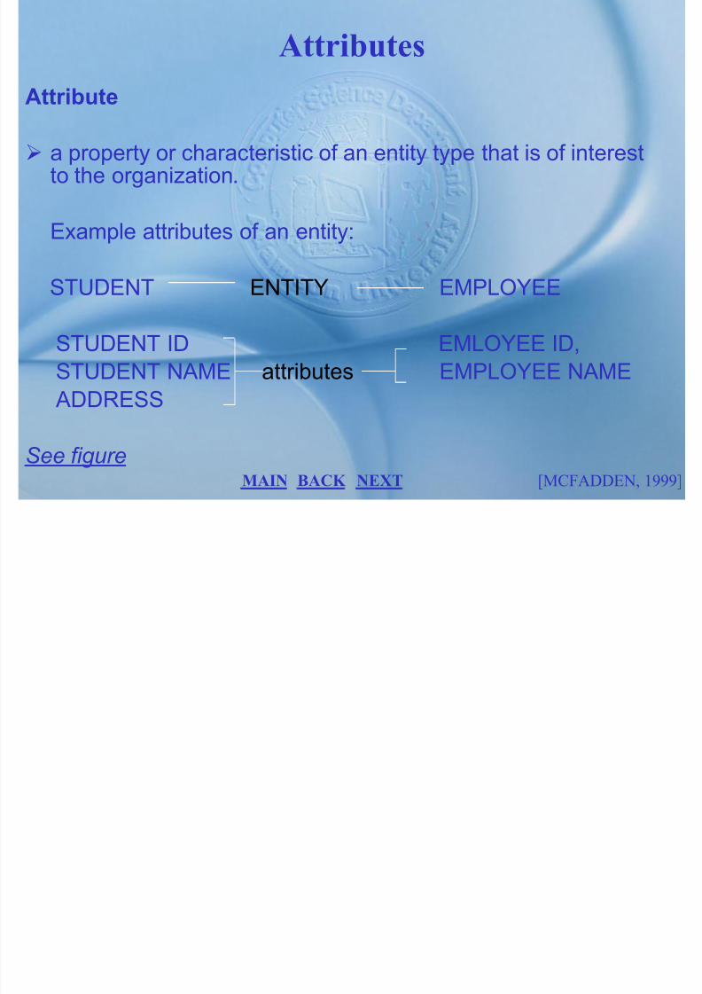
Attributes
Attribute
a property or characteristic of an entity type that is of interestto the organization.
Example attributes of an entity:
STUDENT ENTITY EMPLOYEE
STUDENT ID EMLOYEE ID,
STUDENT NAME attributes EMPLOYEE NAME ADDRESS
See figure BACK NEXT [MCFADDEN, 1999]MAIN
Candidate key

7/27/2019 MELJUN CORTES SYSTEM & ERD DBMS
http://slidepdf.com/reader/full/meljun-cortes-system-erd-dbms 79/396
an attribute (or combination of attributes) that uniquely identifieseach instances of as entity type.
Primary key
a candidate key that has been selected as the identifier for an
entity type. also called an identifier.
primary key values may not be null.
the name of the primary key is underlined on an E-R diagram
BACK NEXT [MCFADDEN, 1994]MAIN

7/27/2019 MELJUN CORTES SYSTEM & ERD DBMS
http://slidepdf.com/reader/full/meljun-cortes-system-erd-dbms 80/396
Multi-valued Attributes

7/27/2019 MELJUN CORTES SYSTEM & ERD DBMS
http://slidepdf.com/reader/full/meljun-cortes-system-erd-dbms 81/396
An attribute that may taken on more than one value for eachentity instance. For example:
Placed inside double-lined ellipse.
Skill is one of the attributes of EMPLOYEE in the preceding entity
examples. Each employee may have more than one skill, so that
SKILL is a multi-valued attribute.
BACK NEXT [MCFADDEN, 1994]
EMPLOYEE
NAME ADDRESS
EMPLOYEE NO. SKILL
MAIN
Relationships
7/27/2019 MELJUN CORTES SYSTEM & ERD DBMS
http://slidepdf.com/reader/full/meljun-cortes-system-erd-dbms 82/396
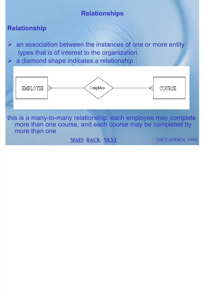
Relationships
Relationship
an association between the instances of one or more entity
types that is of interest to the organization.
a diamond shape indicates a relationship.
this is a many-to-many relationship: each employee may completemore than one course, and each course may be completed bymore than one
BACK NEXT [MCFADDEN, 1994]MAIN

7/27/2019 MELJUN CORTES SYSTEM & ERD DBMS
http://slidepdf.com/reader/full/meljun-cortes-system-erd-dbms 83/396

7/27/2019 MELJUN CORTES SYSTEM & ERD DBMS
http://slidepdf.com/reader/full/meljun-cortes-system-erd-dbms 84/396

7/27/2019 MELJUN CORTES SYSTEM & ERD DBMS
http://slidepdf.com/reader/full/meljun-cortes-system-erd-dbms 85/396
Ternary Relationship

7/27/2019 MELJUN CORTES SYSTEM & ERD DBMS
http://slidepdf.com/reader/full/meljun-cortes-system-erd-dbms 86/396
Ternary Relationship
A simultaneous relationship among instances of three entity
types.
• the relationship Ships tracks the quality of a given part that isshipped by a particular vendor to a selected warehouse.
All three entities are ―many‖ participants.
BACK NEXT [MCFADDEN, 1994]MAIN
Gerund

7/27/2019 MELJUN CORTES SYSTEM & ERD DBMS
http://slidepdf.com/reader/full/meljun-cortes-system-erd-dbms 87/396
Gerund
A many-to-many relationship that the data modeler chooses
to model as an entity type with several associated one-to-many relationships with other entity types.
Sometimes called composite entity.
The diamond symbol is included within the entity rectangle asa reminder that the entity was derived from a relationship.
See figure
Each instances of SHIPMENT represents a real-world shipment
by a given vendor of a particular part to a selected warehouse.The QUANTITY of that shipment is an attribute of SHIPMENT. A
shipment number IS assigned to each shipment and is the primary
key of SHIPMENT.
BACK NEXT [MCFADDEN, 1994]MAIN
Cardinality

7/27/2019 MELJUN CORTES SYSTEM & ERD DBMS
http://slidepdf.com/reader/full/meljun-cortes-system-erd-dbms 88/396
Cardinality
the number of instances of entity B that can (for must) be
associated with each instance of entity A.
See figure
Minimum Cardinality
is a minimum number of instances of entity B may beassociated with each instance of entity A.
Maximum Cardinality
the maximum cardinality is the maximum number of instances
BACK NEXT [MCFADDEN, 1994]MAIN

7/27/2019 MELJUN CORTES SYSTEM & ERD DBMS
http://slidepdf.com/reader/full/meljun-cortes-system-erd-dbms 89/396
Existence dependency

7/27/2019 MELJUN CORTES SYSTEM & ERD DBMS
http://slidepdf.com/reader/full/meljun-cortes-system-erd-dbms 90/396
An instance of one entity cannot exist without the existence of an instance of some other (related) entity.
Weak entity
an entity type that has an existence dependency. For
example:MOVIE COPY is a weak entity.
Identifying relationship
a relationship in which the primary key of the parent entity isused as a part of the primary key of the dependent entity.
See figure
BACK NEXT [MCFADDEN, 1994]MAIN
Multi-Valued Attributes

7/27/2019 MELJUN CORTES SYSTEM & ERD DBMS
http://slidepdf.com/reader/full/meljun-cortes-system-erd-dbms 91/396
Multi Valued Attributes
Multi-Valued Attributes
an attribute that may take on more than one value for agiven entity instance.
MODELING MULTIVALUED ATTRIBUTES
(1) SKILL is an example of a multi-valued attribute of the
EMPLOYEE entity type. A double-lined ellipse is used to
highlight this attribute. Multi-valued attributes are oftenremoved from the entities for which they appear. Each
BACK NEXT [MCFADDEN, 1994]MAIN

7/27/2019 MELJUN CORTES SYSTEM & ERD DBMS
http://slidepdf.com/reader/full/meljun-cortes-system-erd-dbms 92/396
Repeating group

7/27/2019 MELJUN CORTES SYSTEM & ERD DBMS
http://slidepdf.com/reader/full/meljun-cortes-system-erd-dbms 93/396
a set of two or more multi-valued attribute that are logically
related.
Example:
(1) A patient chart example shows typical data for a patient and a
log of that person‘s visit to a medical clinic.(2) An initial E-R representation of the PATIENT entity type withthree multi-valued attributes for each patient: DATE OFVISIT, PHYSICIAN, and SYMPTOM. These are threeattributes that are logically related and form a representing
group (assuming that there is only one visit on a given dateand that a patient sees one physician and is treated for onesymptom only.
See figure
BACK NEXT [MCFADDEN, 1994]MAIN
(3) Shows that the result of removing the repeating group from

7/27/2019 MELJUN CORTES SYSTEM & ERD DBMS
http://slidepdf.com/reader/full/meljun-cortes-system-erd-dbms 94/396
( ) g p g g pPATIENT. A new entity type called PATIENT HISTORY iscreated, and the three multi-valued attributes that composethe repeating group are moved to this entity. DATE OF VISITis chosen as a primary key of this new entity type. There isone-to-many relationship from PATIENT to PATIENT
HISTORY, and PATIENT HISTORY is a weak entity .Removing
the repeating groups during conceptual design results to the ERrepresentation that is clearer to the user and that better models
the real-world situation. See figure.
BACK NEXT [MCFADDEN, 1994]MAIN
Generalization

7/27/2019 MELJUN CORTES SYSTEM & ERD DBMS
http://slidepdf.com/reader/full/meljun-cortes-system-erd-dbms 95/396
the concept that some things (entities) are subtypes pf other, more general things.
A unique aspect of human intelligence is the ability and
propensity to classify object and experience to generalize
their properties. In data modeling, generalization is the
process of defining a more general entity type from a set of
more specialized entity types, thus generalization is a bottom-
up process.
BACK NEXT [MCFADDEN, 1994]MAIN
7/27/2019 MELJUN CORTES SYSTEM & ERD DBMS
http://slidepdf.com/reader/full/meljun-cortes-system-erd-dbms 96/396

7/27/2019 MELJUN CORTES SYSTEM & ERD DBMS
http://slidepdf.com/reader/full/meljun-cortes-system-erd-dbms 97/396
Exclusive Relationship

7/27/2019 MELJUN CORTES SYSTEM & ERD DBMS
http://slidepdf.com/reader/full/meljun-cortes-system-erd-dbms 98/396
The subtype of a supertype are mutually exclusive and each of
the supertype is categorized as exclusive subtype.
See figure
BACK NEXT [MCFADDEN, 1994]MAIN

7/27/2019 MELJUN CORTES SYSTEM & ERD DBMS
http://slidepdf.com/reader/full/meljun-cortes-system-erd-dbms 99/396
Concepts

7/27/2019 MELJUN CORTES SYSTEM & ERD DBMS
http://slidepdf.com/reader/full/meljun-cortes-system-erd-dbms 100/396
p
Normalization
Normalization is a formal process for deciding which attributesshould be grouped together in relation. Before proceeding withphysical design, we need a method to validate the logical
design to this point. Normalization is a primary tool to validateand improve a logical design, so that it satisfies certainconstraints that avoid unnecessary duplication of data.
[MCFADDEN, 1994]BACK NEXT MAIN

7/27/2019 MELJUN CORTES SYSTEM & ERD DBMS
http://slidepdf.com/reader/full/meljun-cortes-system-erd-dbms 101/396
7/27/2019 MELJUN CORTES SYSTEM & ERD DBMS
http://slidepdf.com/reader/full/meljun-cortes-system-erd-dbms 102/396

7/27/2019 MELJUN CORTES SYSTEM & ERD DBMS
http://slidepdf.com/reader/full/meljun-cortes-system-erd-dbms 103/396

7/27/2019 MELJUN CORTES SYSTEM & ERD DBMS
http://slidepdf.com/reader/full/meljun-cortes-system-erd-dbms 104/396
Basic Normal Form

7/27/2019 MELJUN CORTES SYSTEM & ERD DBMS
http://slidepdf.com/reader/full/meljun-cortes-system-erd-dbms 105/396
Now that we have examined functional dependencies and keys,we are ready to describe and illustrate first through third normalforms. We also describe the normalization of summary data thatappear in information bases.
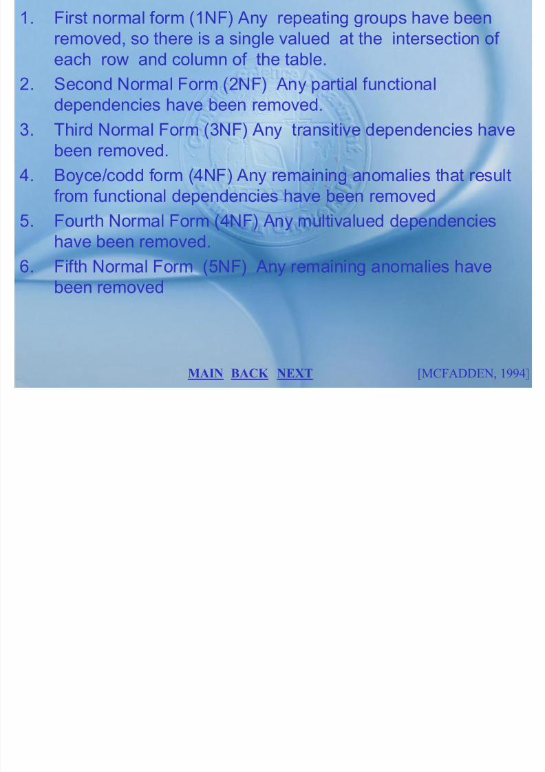
First Normal Form
A relation in first normal form (1nf) if it contains no repeating
groups. Recall that the first property of a relation is that the value
at the intersection of each row and column is atomic. Thus a tablecontains multivalued attributes or repeating groups is not a
reflection. See figure
[MCFADDEN, 1994]BACK NEXT MAIN

7/27/2019 MELJUN CORTES SYSTEM & ERD DBMS
http://slidepdf.com/reader/full/meljun-cortes-system-erd-dbms 106/396
1. The primary key consist of only one attribute (such as theattribute Emp_ID in EMPLOYEE1).

7/27/2019 MELJUN CORTES SYSTEM & ERD DBMS
http://slidepdf.com/reader/full/meljun-cortes-system-erd-dbms 107/396
2. No nonkey attributes exist in the
3. Every nonkey attributes is functionally dependent on the full
set of primary key attributes.
EMPLOYEE2 (See figure) is an example of a relation that is not
in second normal form. The shorthand notation for this relation is
EMPLOYEE2 (Emp_ID, Name, DEPT,SALARY COURSE_DATE
COMPLTED. The functional dependencies in this relation are the
following:
EMPID NAME,DEPT,SALARY
EMPID,COURSEDATE COMPLETED
[MCFADDEN, 1994]BACK NEXT MAIN

7/27/2019 MELJUN CORTES SYSTEM & ERD DBMS
http://slidepdf.com/reader/full/meljun-cortes-system-erd-dbms 108/396

7/27/2019 MELJUN CORTES SYSTEM & ERD DBMS
http://slidepdf.com/reader/full/meljun-cortes-system-erd-dbms 109/396

7/27/2019 MELJUN CORTES SYSTEM & ERD DBMS
http://slidepdf.com/reader/full/meljun-cortes-system-erd-dbms 110/396

7/27/2019 MELJUN CORTES SYSTEM & ERD DBMS
http://slidepdf.com/reader/full/meljun-cortes-system-erd-dbms 111/396
one relation (such as SALES) and as a primary key by using a
dashed underline. The relations in figure are now in third normal

7/27/2019 MELJUN CORTES SYSTEM & ERD DBMS
http://slidepdf.com/reader/full/meljun-cortes-system-erd-dbms 112/396
form, since no transitive dependencies exist. You should verify
that the anomalies that exist in SALES are not present in SALES1
and SPERSON. Transitive dependencies may also occur between
sets of attributes in a relation. For example, the relation
SHIPMENT (SNUM, ORIGIN, DESTINATION,DISTANCE)
Could be used to record shipments according to origin, destination
and distance (Dutka and Hanson,1989). See figure
The functional dependencies in the SHIPMENT relation are
following:
[MCFADDEN, 1994]BACK NEXT MAIN
SNUM ORIGIN, DESTINATION, DISTANCE
ORIGIN,DESTINATION DISTANCE

7/27/2019 MELJUN CORTES SYSTEM & ERD DBMS
http://slidepdf.com/reader/full/meljun-cortes-system-erd-dbms 113/396
There is a transitive dependency in this relation: the DISTANCE
attributes is functionally dependent on the pair of nonkey
attributes ORIGIN and DESTINATION. As a result there are
anomalies in SHIPMENT (as an exercise, you examine this figure
and identify insertion, deletion, and modification anomalies). Wecan remove the transitive dependency in SHIPMENT by
decomposing it onto two relations (both in 3NF):
SHIPTO(Snum, Origin, Destination)
Distances(Origin, Destination, Distance)
[MCFADDEN, 1994]BACK NEXT MAIN

7/27/2019 MELJUN CORTES SYSTEM & ERD DBMS
http://slidepdf.com/reader/full/meljun-cortes-system-erd-dbms 114/396

7/27/2019 MELJUN CORTES SYSTEM & ERD DBMS
http://slidepdf.com/reader/full/meljun-cortes-system-erd-dbms 115/396
major from accounting to finance, we must record this fact inseveral rows in the table.

7/27/2019 MELJUN CORTES SYSTEM & ERD DBMS
http://slidepdf.com/reader/full/meljun-cortes-system-erd-dbms 116/396
The relation also suffer from deletion anomalies; examine the
table and identify at least one example.
SECOND NORMAL FORM
To further normalize this relation, we must analyze the functionaldependencies and select a primary key for the relation. After
discussing the report with users, w e discover that the following
functional dependencies hold:
1. STUDENT ID STUDENT NAME, CAMPUS ADDRESS,MAJOR
[MCFADDEN, 1994]BACK NEXT MAIN
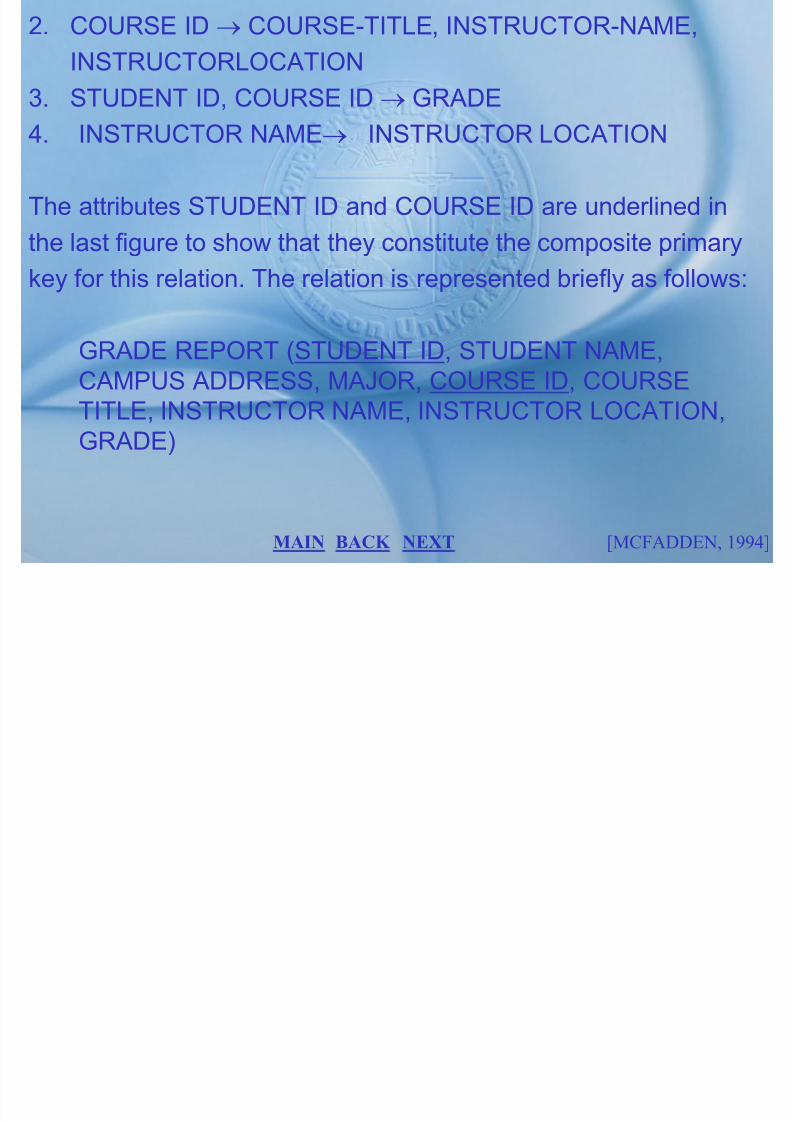
2. COURSE ID COURSE-TITLE, INSTRUCTOR-NAME,
INSTRUCTORLOCATION
7/27/2019 MELJUN CORTES SYSTEM & ERD DBMS
http://slidepdf.com/reader/full/meljun-cortes-system-erd-dbms 117/396
3. STUDENT ID, COURSE ID GRADE
4. INSTRUCTOR NAME INSTRUCTOR LOCATION
The attributes STUDENT ID and COURSE ID are underlined in
the last figure to show that they constitute the composite primary
key for this relation. The relation is represented briefly as follows:
GRADE REPORT (STUDENT ID, STUDENT NAME,CAMPUS ADDRESS, MAJOR, COURSE ID, COURSE
TITLE, INSTRUCTOR NAME, INSTRUCTOR LOCATION,GRADE)
[MCFADDEN, 1994]BACK NEXT MAIN

7/27/2019 MELJUN CORTES SYSTEM & ERD DBMS
http://slidepdf.com/reader/full/meljun-cortes-system-erd-dbms 118/396

7/27/2019 MELJUN CORTES SYSTEM & ERD DBMS
http://slidepdf.com/reader/full/meljun-cortes-system-erd-dbms 119/396
Additional Normal Form
7/27/2019 MELJUN CORTES SYSTEM & ERD DBMS
http://slidepdf.com/reader/full/meljun-cortes-system-erd-dbms 120/396
Relations in third normal form are sufficient for most practicaldatabase applications. However, 3NF does not guarantee that allanomalies have been removed. There are several additionalnormal forms that are designed to remove these anomalies:Boyce-Codd normal form, fourth normal form and fifth normalform. We describe each of these normal forms (as well asdomain key normal form) in this section.
Boyce-codd Normal Form
When a relation has more than one candidate key, anomalies may
[MCFADDEN, 1999]BACK NEXT MAIN

7/27/2019 MELJUN CORTES SYSTEM & ERD DBMS
http://slidepdf.com/reader/full/meljun-cortes-system-erd-dbms 121/396

7/27/2019 MELJUN CORTES SYSTEM & ERD DBMS
http://slidepdf.com/reader/full/meljun-cortes-system-erd-dbms 122/396
We can convert the ST MAJ ADV relation into BCNF by dividing itinto two relations. The attribute that is a determinant but not a

7/27/2019 MELJUN CORTES SYSTEM & ERD DBMS
http://slidepdf.com/reader/full/meljun-cortes-system-erd-dbms 123/396
candidate key (in this case, ADVISOR) must be placed in a
separate relation and must be the key of that relation. The
following two relation result (see figure)
1. ST ADV (STUDENT ID,ADVISOR)
2. ADV MAJ(ADVISOR,MAJOR)
These two relations are in Boyce-Codd normal form and are free
of the types of anomalies associated with ST MAJ ADV. Verify
that these statement are true. The ST MAJ ADV relation can be
re-created by joining the two relations.
[MCFADDEN, 1994]BACK NEXT MAIN

7/27/2019 MELJUN CORTES SYSTEM & ERD DBMS
http://slidepdf.com/reader/full/meljun-cortes-system-erd-dbms 124/396

7/27/2019 MELJUN CORTES SYSTEM & ERD DBMS
http://slidepdf.com/reader/full/meljun-cortes-system-erd-dbms 125/396
division for the OFFERING relation of figure b. notice that therelation called TEACHER contains the INSTRUCTOR attribute,

7/27/2019 MELJUN CORTES SYSTEM & ERD DBMS
http://slidepdf.com/reader/full/meljun-cortes-system-erd-dbms 126/396
while TEXT contains the TEXTBOOK attributes. A relations is in
Fourth normal form (4NF) if it is in BCNF and contains no
multi-valued dependencies. You can easily verify that the two
relations in the figure are 4NF, and you could easily reconstruct
the original relation (OFFERING) by joining these two relations.
FIFTH NORMAL FORM (5NF)
Fifth normal form is designed to cope with a type of dependency
know as a join dependency. When a relation has join dependency,
it cannot be divided into two (or more) relations such that the
resulting tables can be recombined to form the original table. For
[MCFADDEN, 1994]BACK NEXT MAIN

7/27/2019 MELJUN CORTES SYSTEM & ERD DBMS
http://slidepdf.com/reader/full/meljun-cortes-system-erd-dbms 127/396
7/27/2019 MELJUN CORTES SYSTEM & ERD DBMS
http://slidepdf.com/reader/full/meljun-cortes-system-erd-dbms 128/396
MAIN MENU
7/27/2019 MELJUN CORTES SYSTEM & ERD DBMS
http://slidepdf.com/reader/full/meljun-cortes-system-erd-dbms 129/396
PRELIM FINALS
MIDTERM
LABORATORY COURSE SYLLABUS
PHYSICAL DESIGN

7/27/2019 MELJUN CORTES SYSTEM & ERD DBMS
http://slidepdf.com/reader/full/meljun-cortes-system-erd-dbms 130/396
• PHYSICAL DESIGN PROCESS
• DATA VOLUME AND USAGE ANALYSIS
• DATA DISTRIBUTION STRATEGY
• FILE ORGANIZATION
• INDEXES
EXIT
NEXT

7/27/2019 MELJUN CORTES SYSTEM & ERD DBMS
http://slidepdf.com/reader/full/meljun-cortes-system-erd-dbms 131/396
2. User processing requirements that were identified duringrequirements definition, including size and frequency of useof the database and requirements for each of the following:

7/27/2019 MELJUN CORTES SYSTEM & ERD DBMS
http://slidepdf.com/reader/full/meljun-cortes-system-erd-dbms 132/396
of the database, and requirements for each of the following:response times, security, backup, recovery, and retention of
data.3. Characteristics of the database management system (DBMS)
and other components of the computer operatingenvironment.
The steps that are required for physical database design depend
on a number of factors:
• The nature of the target DBMS• Characteristics of the organization's computing environment
[MCFADDEN, 1994]BACK NEXT MAIN

7/27/2019 MELJUN CORTES SYSTEM & ERD DBMS
http://slidepdf.com/reader/full/meljun-cortes-system-erd-dbms 133/396
Data Volume and Usage

7/27/2019 MELJUN CORTES SYSTEM & ERD DBMS
http://slidepdf.com/reader/full/meljun-cortes-system-erd-dbms 134/396
The first step in physical database design is to estimate the size
(or volume) and the usage patterns of the database. Estimates of database size are used to select physical storage devices andestimate the costs of storage. Estimates of usage paths or patterns are used to select file organizations and access methods,to plan for the use of indexes, and to plan a strategy for data
distribution.
Data Volume Analysis
The next figure shows a simplified picture of the logical datamodel for Mountain View Community Hospital. Each entity is
represented by a rectangle, but the attributes have been omitted.
BACK NEXT [MCFADDEN, 1994]MAIN
Data Usage Analysis

7/27/2019 MELJUN CORTES SYSTEM & ERD DBMS
http://slidepdf.com/reader/full/meljun-cortes-system-erd-dbms 135/396
In data usage analysis, the analyst identifies the major
transactions and processes required against the database. Eachtransaction and process is then analyzed to determine the access
paths used and the estimated frequency of use. When all
transactions have been analyzed, the composite load map is
prepared, showing the total usage of access paths on theconceptual model. See figure.
[MCFADDEN, 1994]BACK NEXT MAIN
A detailed analysis of each step in the access path is entered at
the bottom of the form. The type of access to each entity isrecorded using the following codes:

7/27/2019 MELJUN CORTES SYSTEM & ERD DBMS
http://slidepdf.com/reader/full/meljun-cortes-system-erd-dbms 136/396
recorded using the following codes:
C: create (or insert) a new entity R: read an entity
U: update an entity
D: delete an entity
Transaction map is a diagram that shows the sequence of logicaldatabase accesses.
[MCFADDEN, 1994]BACK NEXT MAIN
Composite Usage Map

7/27/2019 MELJUN CORTES SYSTEM & ERD DBMS
http://slidepdf.com/reader/full/meljun-cortes-system-erd-dbms 137/396
is a concise reference to the estimated volume and usage of
data in the database.
It provides a basis of remaining steps of physical databasedesign, during which the analysts must design storagestructures and access strategies to optimize performance.
[MCFADDEN, 1994]BACK NEXT MAIN
Data Distribution Strategy

7/27/2019 MELJUN CORTES SYSTEM & ERD DBMS
http://slidepdf.com/reader/full/meljun-cortes-system-erd-dbms 138/396
The whole condition and configuration databases corresponding
to the transferred data will be distributed at the same time. Later,it will be possible to transfer only the necessary part of thecondition and configuration database.
The condition and configuration databases will also be madeavailable separately on a regular basis. A database to keep trackof the cartridge moving will be necessary, but does not exist yet.The expert system will run on dedicated machines.
BACK NEXT [MCFADDEN, 1999]MAIN
BASIC DATA DISTRIBUTION STRATEGIES:
1. Centralized. All data are located at a single site. Although this

7/27/2019 MELJUN CORTES SYSTEM & ERD DBMS
http://slidepdf.com/reader/full/meljun-cortes-system-erd-dbms 139/396
1. Centralized. All data are located at a single site. Although thissimplifies the implementation, there are at least three
disadvantages: (a) Data are not readily accessible to users atremote sites, (b) data communication costs may be high, and(c) the database system fails totally when the central systemfails.
2. Partitioned. The database is divided into disjoint (non
overlapping) partitions. Each partition (also called fragment )is assigned to a particular site. The major advantage of thisapproach is that data is moved closer to local users and so ismore accessible.
3. Replicated . A full copy of the database is assigned to morethan one site in the network. This assignment maximizeslocal access to data but creates update problems, since eachdatabase change must be reliably processed andsynchronized at all of the sites.
[MCFADDEN, 1994]BACK NEXT MAIN

7/27/2019 MELJUN CORTES SYSTEM & ERD DBMS
http://slidepdf.com/reader/full/meljun-cortes-system-erd-dbms 140/396
File Organizations

7/27/2019 MELJUN CORTES SYSTEM & ERD DBMS
http://slidepdf.com/reader/full/meljun-cortes-system-erd-dbms 141/396
File organization
is a technique for physically arranging the records of a file onsecondary storage devices. The criteria that are normallyimportant in selecting file organizations include:
1. Fast access for retrieval
2. High throughput for processing transactions
3. Efficient use of storage space
4. Protection from failures or data loss
5. Minimizing need for reorganization
[MCFADDEN, 1994]BACK NEXT MAIN
6. Accommodating growth
7 Security from unauthorized use

7/27/2019 MELJUN CORTES SYSTEM & ERD DBMS
http://slidepdf.com/reader/full/meljun-cortes-system-erd-dbms 142/396
7. Security from unauthorized use
Often theses objectives are conflicting, and the designer must
select a file organization that provides a reasonable balance
among the criteria within the resources available.
[MCFADDEN, 1999]BACK NEXT MAIN
Sequential File Organization
the records in the file are stored in sequence according to a
7/27/2019 MELJUN CORTES SYSTEM & ERD DBMS
http://slidepdf.com/reader/full/meljun-cortes-system-erd-dbms 143/396
q gprimary key value (See figure).
The location of a particular record in the file is not known bythe storage organization.
To locate a particular record, the user must normally scan the file
from the beginning until the desired record is located. Aneveryday example of a sequential file is the alphabetical list of persons in the white pages of a phone directory (ignoring anyindex that may be included with the directory pages).
[MCFADDEN, 1999]BACK NEXT MAIN
Indexed File Organization
the records are either stored sequentially or non-sequentially,d i d i d h ll h l

7/27/2019 MELJUN CORTES SYSTEM & ERD DBMS
http://slidepdf.com/reader/full/meljun-cortes-system-erd-dbms 144/396
and an index is created that allows the user to locateindividual records.
Index
is a table or other data structure that is used to determine the
location of rows in a table (or tables) that satisfy somecondition.
There are two basic types of indexed file organizations: indexedsequential and indexed nonsequential.
[MCFADDEN, 1999]BACK NEXT MAIN
Indexed Sequential
When the records are stored sequentially by primary key value, ai l i d ( ll d bl k i d ) b d (S fi )

7/27/2019 MELJUN CORTES SYSTEM & ERD DBMS
http://slidepdf.com/reader/full/meljun-cortes-system-erd-dbms 145/396
simple index (called a block index ) may be used (See figure).This approach (called indexed sequential ) has been the mostcommon file organization for pre-database systems. Aneveryday example of a simple indexed sequential file is againthe list of persons in the white pages of a phone directory.
Indexed Nonsequential
When the records in an indexed organization are storednonsequentially, a full index (frequently called an inverted index ) is required. The arrangement of books in a library, and
the accompanying computerized indexes (or catalogs)provide everyday example of an indexed nonsequential fileorganization.
[MCFADDEN, 1999]BACK NEXT MAIN
Hashed
In a hashed file organization the address for each record isdetermined using a hashing algorithm (See figure)

7/27/2019 MELJUN CORTES SYSTEM & ERD DBMS
http://slidepdf.com/reader/full/meljun-cortes-system-erd-dbms 146/396
determined using a hashing algorithm (See figure).
Hashing algorithm
is a routine that converts a primary key value into a relativerecord number (or relative file address).
As a result of using a hashing algorithm, in general the recordsare located nonsequentially in the file. A typical hashingalgorithm uses the technique of dividing the remainder of thedivision as the relative storage location.
[MCFADDEN, 1999]BACK NEXT MAIN
Indexes

7/27/2019 MELJUN CORTES SYSTEM & ERD DBMS
http://slidepdf.com/reader/full/meljun-cortes-system-erd-dbms 147/396
Most database manipulations require locating a row (or collection
of rows) that satisfies some condition. For example, we may
want to retrieve all customers in a given zipcode or all students
with particular major. Scanning every row in a table looking for
the desired rows may be unacceptably slow, particularly whenthe tables are large, as they often are in real-world.
applications. Using indexes can greatly speed up this process,
and defining indexes is an important part of the physical
database design.
[MCFADDEN, 1994]BACK NEXT MAIN

7/27/2019 MELJUN CORTES SYSTEM & ERD DBMS
http://slidepdf.com/reader/full/meljun-cortes-system-erd-dbms 148/396
Primary Key Indexes
In most relational DBMSs, you can create an index by specifying

7/27/2019 MELJUN CORTES SYSTEM & ERD DBMS
http://slidepdf.com/reader/full/meljun-cortes-system-erd-dbms 149/396
In most relational DBMSs, you can create an index by specifyingyou want a column indexed at the time you define the table.
You may also create the index in directly by issuing a followingSQL command. For example:
CREATE UNIQUE INDEX PRODINDX ON PRODUCT
PRODUCT_NO);
A unique index performs two important functions: is provides fastaccess to specific records and enforces uniqueness of primarykey values.
[MCFADDEN, 1994]BACK NEXT MAIN
Indexes For Nonkey Attribute
Database users often wish to retrieve rows of a relation based onl f k tt ib t F l i th PRODUCT
7/27/2019 MELJUN CORTES SYSTEM & ERD DBMS
http://slidepdf.com/reader/full/meljun-cortes-system-erd-dbms 150/396
values for non-key attributes. For example, in the PRODUCTtable, users may want to retrieve records that satisfy anycombination of the following conditions:
1. All table (DESCRIPTION=‘Table‘) 2. All oak furniture (FINISH=‘Oak‘)
3. All dining room furniture (ROOM=‘DR‘) 4. All furniture priced below $500 (Price<500)
To speed up retrievals, we can define an index on each non-key
attribute that we use to qualify retrieval.
[MCFADDEN, 1994]BACK NEXT MAIN
Clustering Indexes
When the records in a file are often retrieved based on the values

7/27/2019 MELJUN CORTES SYSTEM & ERD DBMS
http://slidepdf.com/reader/full/meljun-cortes-system-erd-dbms 151/396
of the non-key attribute, retrievals can be speed up by
physically ordering the file on that non-key attribute.
Clustering Attribute
when the records of the file are physically ordered on a non-keyattribute that does not have a distinct value for each record.
is any non-key attribute in a record (or row) that is used tocluster (or group together) the rows that have a common value
for this attribute.
[MCFADDEN, 1994]BACK NEXT MAIN
Clustering Field
is an index defined on the clustering attribute of a file.
7/27/2019 MELJUN CORTES SYSTEM & ERD DBMS
http://slidepdf.com/reader/full/meljun-cortes-system-erd-dbms 152/396
Trees
Structures of Trees
Tree
is a data structure that consists of a set of nodes that branchout from a node at the top of the tree.
Root node
is the node at the top of a tree.
[MCFADDEN, 1994]BACK NEXT MAIN
Leaf node
is a node in a tree that has no child nodes.

7/27/2019 MELJUN CORTES SYSTEM & ERD DBMS
http://slidepdf.com/reader/full/meljun-cortes-system-erd-dbms 153/396
Subtree
consists of that node and all the descendants of that node.
Branching factor (or degree of a tree)
is the maximum number of children allowed per parent.
[MCFADDEN, 1994]BACK NEXT MAIN
Depth
is the number of levels between the root node and aleaf node in the tree

7/27/2019 MELJUN CORTES SYSTEM & ERD DBMS
http://slidepdf.com/reader/full/meljun-cortes-system-erd-dbms 154/396
leaf node in the tree.
Depth may be the same from the root node to each leaf node,producing a tree called a balanced tree
Balanced trees
are democratic in that all leaf nodes have about the same accesscosts; however, balancing can be costly to maintain as the treecontents are updated.
[MCFADDEN, 1994]BACK NEXT MAIN
RELATIONAL DATABASEIMPLEMENTATION

7/27/2019 MELJUN CORTES SYSTEM & ERD DBMS
http://slidepdf.com/reader/full/meljun-cortes-system-erd-dbms 155/396
• RELATIONAL DATA DEFINITION IN SQL
• DATA RETRIEVAL AND MANIPULATION
• MULTIPLE TABLE OPERATIONS
EXIT
NEXT
Relational Data definition in SQL

7/27/2019 MELJUN CORTES SYSTEM & ERD DBMS
http://slidepdf.com/reader/full/meljun-cortes-system-erd-dbms 156/396
To illustrate the use of typical relational DDLs (Data DefinitionLanguage), we refer to the Mountain View Community Hospital(MVCH) database See figure. The list (next slide) contains a list of the commands necessary to define this database using the SQLDDL of dBASE IV. Not shown in the list or subsequent SQL
commands is a special symbol used in some SQLimplementations --a line-continuation character. For example, ininteractive mode, SQL/DS (IBM Corp., 1991) interprets each 80-character line as one free-format text command. Thus, if a
command cannot all fit on one line, it must be continued, andSQL/DS must be told to wait to process the command until alllines for that command have been entered. In SQL/DS this
[MCFADDEN, 1994]BACK NEXT MAIN
continuation symbol is the hyphen (-), which is placed at the endof a continued line. In most SQL versions, a semicolon designatesthe end of the command, as in the dBASE version of SQL.

7/27/2019 MELJUN CORTES SYSTEM & ERD DBMS
http://slidepdf.com/reader/full/meljun-cortes-system-erd-dbms 157/396
CREATE TABLE ROOM(LOCATION CHAR (4), ACCOM CHAR (2),EXTENSION SMALLINT,
PATIENT_NO INTEGER);
CREATE TABLE PATIENT(PATIENT_NO INTEGER,DATE_DISCH DATE,… Other data elements…);
[MCFADDEN, 1994]BACK NEXT MAIN
CREATE TABLE PHY(PHY_ID CHAR (10),PHY_PHONE CHAR (8));

7/27/2019 MELJUN CORTES SYSTEM & ERD DBMS
http://slidepdf.com/reader/full/meljun-cortes-system-erd-dbms 158/396
CREATE TABLE ITEM(ITEM_CODE SMALLINT,DESCRIPT CHAR (15));
CREATE TABLE ATTENDS
(PHY_ID CHAR (10),PATIENT_NO INTEGER,PROCEDURE CHAR (15));
CREATE TABLE BILLED(PATIENT_NO INTEGER,
[MCFADDEN, 1994]BACK NEXT MAIN
ITEM_CODE SMALLINT,CHARGE DECIMAL (7,2));
Data Types

7/27/2019 MELJUN CORTES SYSTEM & ERD DBMS
http://slidepdf.com/reader/full/meljun-cortes-system-erd-dbms 159/396
Data Types
The types for the dBASE SQL system follow:
DECIMAL(m,n) Signed numbers, where m is the total number of digits (including sign), and n is the number of digits to the right
of the decimal point (examples: a part's unit weight or dimensions).INTEGER Large (up to 11 digits) positive or negative wholenumbers (examples: a country's population or the quantity on
hand of a part).SMALLINT Small (5 or 6 digits, depending on the DBMS) positiveor negative whole numbers. By specifying this data type, less
[MCFADDEN, 1994]BACK NEXT MAIN
storage space is required (examples: age, temperature, or anairline flight number).FLOAT(m,n) Whole and fractional numbers represented inscientific notation where m is the total number of digits (including

7/27/2019 MELJUN CORTES SYSTEM & ERD DBMS
http://slidepdf.com/reader/full/meljun-cortes-system-erd-dbms 160/396
scientific notation, where m is the total number of digits (includingsign), and n is the number of digits to the right of the decimal point(example: engineering specifications).CHAR(n) Alphanumeric (character) data, where n is the maximumlength for this character string; n character positions are allocatedto each instance of CHAR column (examples: customer name or
product description).DATE Calendar dates. A system variable can be used to set theformat for the date data type -- for example, month/ day/ year or year/ month/ day (examples: order date or subscription
anniversary date).LOGICAL True or false values.
[MCFADDEN, 1994]BACK NEXT MAIN

7/27/2019 MELJUN CORTES SYSTEM & ERD DBMS
http://slidepdf.com/reader/full/meljun-cortes-system-erd-dbms 161/396
Data Definition Commands
Including CREATE TABLE, seven SQL DDL commands aretypically available in SQL DBMSs:

7/27/2019 MELJUN CORTES SYSTEM & ERD DBMS
http://slidepdf.com/reader/full/meljun-cortes-system-erd-dbms 162/396
typically available in SQL DBMSs:
CREATE TABLE Defines a new table and its columns.DROP TABLE Destroys a table (definition and contents as wellas any views and indexes associated with it). Usually only thetable creator may delete the table.
ALTER TABLE Adds one or more new columns to a table.Usually only the table creator may add columns to the table.CREATE INDEX Defines an index on one column (or aconcatenation of columns) that enables rapid access to the rows
of a table in a sequence or randomly by key value. A table mayhave many indexes, and each index may be specified to beUNIQUE (primary key) or not and may be sequenced inascending or descending order.
[MCFADDEN, 1994]BACK NEXT MAIN
DROP INDEX Destroys an index. Usually only the table creator may delete an index of that table.CREATE VIEW Defines a logical table from one or more tables or views (Views may not be indexed ) There are limitations on

7/27/2019 MELJUN CORTES SYSTEM & ERD DBMS
http://slidepdf.com/reader/full/meljun-cortes-system-erd-dbms 163/396
views. (Views may not be indexed.) There are limitations onupdating data through a view, but some updating of data througha view is permitted.DROP VIEW Destroys a view definition (and any other viewsdefined from the deleted view). Usually only the creator of theview's base tables may delete a view.
Null Value: A special column value, distinct from 0, blank, or anyother value, that indicates that the value for the column is missingor otherwise unknown.
Column Controls.
A column may assume a special value, called a null value, when
[MCFADDEN, 1994]BACK NEXT MAIN
the value for that column in a given raw is missing or unknown.Null is distinct from 0 or blank, which may be legitimate, knownvalues for a column. NOT NULL is an integrity control in someSQL systems that tells the DBMS not to permit a null value for a

7/27/2019 MELJUN CORTES SYSTEM & ERD DBMS
http://slidepdf.com/reader/full/meljun-cortes-system-erd-dbms 164/396
SQL systems that tells the DBMS not to permit a null value for aspecific column of any row in the table. For example, in thedefinition ITEM table in Figure 8-1, the ITEM_CODE columnshould be NOT NULL. The NOT NULL control is enforced on alldata update statements. You usually apply NOT NULL to keyfields (the relational data model requires that primary key columns
be not null), but you may apply NOT NULL to any column asappropriate (for example, a cross-reference key may be NOTNULL).
UNIQUE is another column integrity control that specifies that thevalues of a column must be unique across all rows of the table.You use UNIQUE only with single columns, so uniqueconcatenated keys can only be handled by creating a unique
[MCFADDEN, 1994]BACK NEXT MAIN
index.
Changing Table Definitions

7/27/2019 MELJUN CORTES SYSTEM & ERD DBMS
http://slidepdf.com/reader/full/meljun-cortes-system-erd-dbms 165/396
You may change table definitions in many SQL RDBMSs by ALTERing column specifications. In dBASE IV, the ALTER TABLEcommand adds new columns to an existing table. For example,we could add a patient name column to the PATIENT table by
ALTER TABLE PATIENT ADD ( NAME CHAR (20) );
The NAME column is added to the end of existing rows, and
values are initialized with blanks. We may not drop previouslydefined columns or change data type of an existing column. Todrop a column, you must define a view on the base table thatomits the column no longer desired, or you may create a new
[MCFADDEN, 1994]BACK NEXT MAIN
table, leaving out the column to be dropped, and then insert thedata from the previous table into the new one. The ALTERcommand is invaluable for adapting the database to inevitablemodifications due to changing requirements, prototyping,
7/27/2019 MELJUN CORTES SYSTEM & ERD DBMS
http://slidepdf.com/reader/full/meljun-cortes-system-erd-dbms 166/396
modifications due to changing requirements, prototyping,evolutionary development, and mistakes.
Additional Table Definition Features
Like many SQL-based systems, dBASE provides several
commands to assist in documenting table definitions and with theflexibility of using defined data:
CREATE Specifies an alternative name for a table or view; often
used.SYNONYM to define an abbreviation to reduce the number of keystrokes needed when referring to a table or view.
[MCFADDEN, 1994]BACK NEXT MAIN

7/27/2019 MELJUN CORTES SYSTEM & ERD DBMS
http://slidepdf.com/reader/full/meljun-cortes-system-erd-dbms 167/396
The following are examples of the use of some of thesecommands for the ITEM table and its DESCRIPT column:
COMMENT ON ITEM COLUMN DESCRIPTION

7/27/2019 MELJUN CORTES SYSTEM & ERD DBMS
http://slidepdf.com/reader/full/meljun-cortes-system-erd-dbms 168/396
COMMENT ON ITEM COLUMN DESCRIPTIONIS ' Selected from medical dictionary of terms';CREATE SYNONYM IT FOR ITEM;DROP SYNONYM IT;LABEL ON TABLE ITEM COLUMN DESCRIPTIS 'Standard Description';
View Definition
The often-stated purpose of a view is to simply query commands,
but a view may also provide valuable data security andsignificantly enhance programming productivity for a database. Tohighlight the convenience of a view, consider the Patient BillConstruction of the lines of this bill requires access to three tables
[MCFADDEN, 1994]BACK NEXT MAIN
from the MVCH database : PATIENT, BILLED, and ITEM. Anovice database user may make mistakes or be unproductive inproperly formulating queries involving so many tables. A viewallows us to predefine this association into a single virtual table as

7/27/2019 MELJUN CORTES SYSTEM & ERD DBMS
http://slidepdf.com/reader/full/meljun-cortes-system-erd-dbms 169/396
allows us to predefine this association into a single virtual table aspart of the database. With this view, a user who wants onlyPatient Bill data does not have to reconstruct the joining of data toproduce the report or any subset of it. We define a view,DET__BILL, by specifying an SQL query that has the view as itsresult. For the Patient Bill, this would be
CREATE VIEW DET__BILL ASSELECT BILLED. PATIENT__NO, BILLED. ITEM__CODE:
DESCRIPT, CHANGE, NAME and other columns as required
FROM PATIENT, BILLED, ITEMWHERE PATIENT. PATIENT__NO BILLED.PATIENT__NO
AND ITEM. ITEM __CODE=BILLED. ITEM__CODE:
[MCFADDEN, 1994]BACK NEXT MAIN
The SELECT clause specifies what data elements (columns) areto be included in the view table. The FROM clause lists the tablesinvolved in the view development. The WHERE clause specifiesthe names of the common columns used to join BILLED to ITEM

7/27/2019 MELJUN CORTES SYSTEM & ERD DBMS
http://slidepdf.com/reader/full/meljun-cortes-system-erd-dbms 170/396
jand to PATIENT. Because a view is a table, and one of therelational properties of tables is that the order of rows isimmaterial, the rows in a view may not be sorted (the ORDER BYclause in SQL). However, queries that refer to this view maydisplay their results in any desired sequence. A view is not
maintained as real data; rather it is constructed automatically asneeded by the DBMS. Therefore, a view is a virtual table. A viewalways contains the most current derived values and is thussuperior in terms of data currency to constructing a temporary real
table from several base tables. Also in comparison to a temporaryreal table, a view is costly, however, since its contents must becalculated each time they are requested. A view may join multipletables or other views together and may contain derived (or virtual)
[MCFADDEN, 1994]BACK NEXT MAIN
columns. For example, a user in Mountain View CommunityHospital may simply want to know the total charges by patient for room and special items in the room (item codes between 200 and300). A view for just this aggregate data can be created from the

7/27/2019 MELJUN CORTES SYSTEM & ERD DBMS
http://slidepdf.com/reader/full/meljun-cortes-system-erd-dbms 171/396
) j gg gDET__BILL view as follows:
CREATE VIEW ROOM__CHG (OCCUPANT, RM__CHGS) AS
SELECT NAME, SUM (CHARGE)
WHERE ITEM__CODE BETWEEN 200 AND 300GROUP BY NAME;
As this view shows, we can assign a different name to a viewcolumn than the associated base table or expression columnname. Here, OCCUPANT is a renaming of NAME, local to onlythis view, and RM__CHGS is the column name in this view giventhe expression for total charges by patient. Now this expression
[MCFADDEN, 1994]BACK NEXT MAIN

7/27/2019 MELJUN CORTES SYSTEM & ERD DBMS
http://slidepdf.com/reader/full/meljun-cortes-system-erd-dbms 172/396
Some people advocate the creation of a view for every singlebase table. They suggest this approach because views cancontribute to greater programming productivity as databaseevolve. Consider a situation where 50 programs all use the

7/27/2019 MELJUN CORTES SYSTEM & ERD DBMS
http://slidepdf.com/reader/full/meljun-cortes-system-erd-dbms 173/396
p gBILLED table. Suppose that the MVCH database evolves to
support new functions that require the BILLED table torenormalized into two tables. If these 50 programs refer directly tothe BILLED base table, they will all have to be modified to refer toone of the two new tables, or to join the tables together. On the
other hand, if these programs all use the view on this base table,then only the view has to be re-created, saving considerablereprogramming effort. You should remember, however, that viewsrequire considerable run-time computer processing, since the
virtual table of a view is recreated each time the view isreferenced. Therefore, referencing a base table through a viewrather than directly can add considerable time to query
[MCFADDEN, 1994]BACK NEXT MAIN
processing. This additional operational cost must be balancedagainst the potential reprogramming savings of a view. Updatingdata directly from a view rather than from base tables is possibleunder certain limitations outlined in a later section, "Modifying

7/27/2019 MELJUN CORTES SYSTEM & ERD DBMS
http://slidepdf.com/reader/full/meljun-cortes-system-erd-dbms 174/396
, y gData Through a View." Some update operations to data in a view
are permitted, as long as the update is unambiguous in terms of data modification in the base table.
Internal Schema Definition in RDBMs
The internal schema of a relational database can be controlled for processing and storage efficiency. Typically a database designer can tune the operational performance of the internal data model of
a relational database by one or more of the following techniques:
1. Choosing to index primary and/or secondary keys to increasethe speed of row selection, table joining, and row ordering
[MCFADDEN, 1994]BACK NEXT MAIN
(and to drop indexes to increase speed of table updating).You may want to review the section in Chapter 7 on selectingindexes.
2. Selecting file organizations for base tables that match thet f i ti it th t bl (f l k

7/27/2019 MELJUN CORTES SYSTEM & ERD DBMS
http://slidepdf.com/reader/full/meljun-cortes-system-erd-dbms 175/396
type of processing activity on those tables (for example, keep
table physically sorted by a frequently used reporting sortkey).3. Selecting file organizations for indexes (which are also tables)
suitable for how the indexes are used, and allocating extraspace for an index file, so that an index can grow withouthaving to be reorganize.
4. Clustering data, so that related rows of frequently joinedtables are stored close together in secondary storage tominimize retrieval time.
5. Maintaining statistics about tables and their indexes, so thatthe DBMS can find the most efficient ways to perform variousdatabase operations.
Not all of these techniques are available in all SQL systems.Techniques 1 and 4 are typically available, so we discuss these in
[MCFADDEN, 1994]BACK NEXT MAIN
the following sections.
Indexes

7/27/2019 MELJUN CORTES SYSTEM & ERD DBMS
http://slidepdf.com/reader/full/meljun-cortes-system-erd-dbms 176/396
You can create indexes in most RDBMSs to provide rapid random
and sequential access to base-table data. (Although users do notdirectly refer to indexes when writing any SQL command, theDBMS recognizes when and which existing indexes wouldimprove query performance.) You can usually create indexes for
both primary and secondary keys and often both singleconcatenated (multiple-column) keys. In some systems, you canchoose between ascending or descending sequence for the keysin an index. For example, to create an index on the ATTENDSrelation for the PHY__ID column (a secondary key) in dBASE'sSQL, we would write
CREATE INDEX PHYSON ATTENDS (PHY__ID);
[MCFADDEN, 1994]BACK NEXT MAIN
To create a concatenated key index on the BILLED relation for PATIENT__NO and ITEM__CODE (a primary key), we wouldwrite
CREATE UNIQUE INDEX PAT__ITEM

7/27/2019 MELJUN CORTES SYSTEM & ERD DBMS
http://slidepdf.com/reader/full/meljun-cortes-system-erd-dbms 177/396
ON BILLED (PATIENT__NO, ITEM__CODE);
Indexes may be created at any time. If data already exist in thekey column(s), index population will automatically occur for theexisting data. If an index is defined as UNIQUE and the existing
data violates this condition, the index creation will be rejected.Indexes will remain up to date with subsequent data maintenance.When we no longer need tables, views, or indexes, we can usethe associated DROP statements. For example, to delete thePHYS index above, we would use
DROP INDEX PHYS;
[MCFADDEN, 1994]BACK NEXT MAIN
Several cautions should be applied when deciding on indexcreation. First, an index consumers extra storage space andrequires maintenance time when indexed data change value.Together, these costs may noticeably retard retrieval response

7/27/2019 MELJUN CORTES SYSTEM & ERD DBMS
http://slidepdf.com/reader/full/meljun-cortes-system-erd-dbms 178/396
times and cause annoying delays for a query. A system may use
only one index even if several are available for keys in a complexqualification. The database designer must know exactly howindexes are used by the particular RDBMS to make wise choiceson indexing. With SQL/DS, the Relational Design Tool
understands the SQL/DS query-processing algorithms and can bevery helpful in picking the right combination of indexes.
Row Clustering
A feature now becoming common in RDBMS is the ability tocluster rows of different tables into adjacent physical storage tominimize access between related tables. Remember, the
[MCFADDEN, 1994]BACK NEXT MAIN
relational model assumes that a table is a logical construct, soa table need not correspond to a physical file of contiguousrecords. For example, in Oracle (Oracle Corp., 1988) we canspecify that we want ATTENDS rows for a given PATIENT to be

7/27/2019 MELJUN CORTES SYSTEM & ERD DBMS
http://slidepdf.com/reader/full/meljun-cortes-system-erd-dbms 179/396
clustered with the associated PATIENT table row for that patient, as
follows:
CREATE CLUSTER PATINT__DATA(PATIENT__NO INTEGER NOT NULL)
ALTER CLUSTER PATIENT__DATA ADD TABLE PATIENTWHERE PATIENT. PATIENT__NO = PATIENT__DATA.
PATIENT__NO ALTER CLUSTER PATIENT__DATA
ADD TABLE ATTENDSWHERE ATTENDS. PATIENT__NO = PATIENT__DATA.
PATIENT__NO
[MCFADDEN, 1994]BACK NEXT MAIN
on allowing null values (especially for primary key columns), andforcing values of foreign and cross-reference keys to exist in other tables. The SQL 1989 standard introduced a syntax for referentialintegrity control. Referential integrity involves two tables in a 1:M
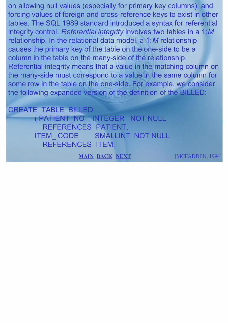
7/27/2019 MELJUN CORTES SYSTEM & ERD DBMS
http://slidepdf.com/reader/full/meljun-cortes-system-erd-dbms 180/396
relationship. In the relational data model, a 1:M relationship
causes the primary key of the table on the one-side to be acolumn in the table on the many-side of the relationship.Referential integrity means that a value in the matching column onthe many-side must correspond to a value in the same column for
some row in the table on the one-side. For example, we consider the following expanded version of the definition of the BILLED:
CREATE TABLE BILLED( PATIENT_NO INTEGER NOT NULL
REFERENCES PATIENT,ITEM_ CODE SMALLINT NOT NULL
REFERENCES ITEM,
[MCFADDEN, 1994]BACK NEXT MAIN
CHARGE DECIMAL (7,2) );
The REFERENCES clause for PATIENT_NO states that for eachrow of the BILLED table there must be exactly one raw in the

7/27/2019 MELJUN CORTES SYSTEM & ERD DBMS
http://slidepdf.com/reader/full/meljun-cortes-system-erd-dbms 181/396
PATIENT table whose PATIENT_NO column (the primary key of
that table) value is the same as the PATIENT_NO value inBILLED. Referential integrity ensures there will never be amismatch between related tables, even after updates and deletes.Full referential integrity is sometimes too restrictive. To deal with
such restrictiveness, the latest SQL standard has added twoadditional clauses related to referential integrity: ON DELETE andON UPDATE clauses. For the BILLED table, consider thefollowing extension to the example in the previous slide:
CREATE TABLE BILLED(PATIENT_NO INTEGER
[MCFADDEN, 1994]BACK NEXT MAIN
REFERENCES PATIENT,ON DELETE SET NULL,. . .

7/27/2019 MELJUN CORTES SYSTEM & ERD DBMS
http://slidepdf.com/reader/full/meljun-cortes-system-erd-dbms 182/396
ON DELETE tells the DBMS what to do with rows, for example, in
the BILLED table when a PATIENT row is deleted. ON DELETESET NULL tells the DBMS to allow the deletion, but to set thePATIENT_NO in BILLED for corresponding rows to the null value.
As an alternative, consider the following:
CREATE TABLE BILLED(PATIENT_NO INTEGER DEFAULT 9999
REFERENCES PATIENTON DELETE SET DEFAULTON UPDATE CASCADE,
. . .
[MCFADDEN, 1994]BACK NEXT MAIN
ON DELETE SET DEFAULT tells the DBMS to allow the deletion,but to set the PATIENT_NO in BILLED for corresponding rows tothe default for this column. ON UPDATE deals with, for example,what to do if a patient is assigned a new number. ON UPDATE

7/27/2019 MELJUN CORTES SYSTEM & ERD DBMS
http://slidepdf.com/reader/full/meljun-cortes-system-erd-dbms 183/396
CASCADE says that when a PATIENT_NO in the PATIENT table
changes, all the corresponding PATIENT_NOs in the BILLEDtable should also change to the new value. Another type of integrity control added in SQL-89 was global constraints, or assertions. For example, consider the following extension to the
PHY table and the following constraint on the MVCH database:
CREATE TABLE PHY( PHY__ID CHAR (10) NOT NULL UNIQUE,PHY__PHONE CHAR (8)SALARY DECIMAL (9,2) );
[MCFADDEN, 1994]BACK NEXT MAIN
CREATE ASSERTION PHY__BUDGETCHECK (SELECT SUM (SALARY) FROM PHY <=10000000);
Th CHECK l i th PHY BUDGET ti th t

7/27/2019 MELJUN CORTES SYSTEM & ERD DBMS
http://slidepdf.com/reader/full/meljun-cortes-system-erd-dbms 184/396
The CHECK clause in the PHY_BUDGET assertion ensures that
the salary budget for physicians is no greater than $10 million.This assertion could be changed each year as a new budget isapproved. Without referential integrity controls, a database canbecome full orphan rows that can be either forgotten or
mishandled.
Referential integrity:
An integrity constraint that specifies that the value (or existence)
of an attribute in one relation depends on the value (or existence)of the same attribute in another relation.
[MCFADDEN, 1994]BACK NEXT MAIN
Data Dictionary Facilities
Since RDBMSs typically store table, column, and view definitions,along with integrity rules, security constraints, and other data

7/27/2019 MELJUN CORTES SYSTEM & ERD DBMS
http://slidepdf.com/reader/full/meljun-cortes-system-erd-dbms 185/396
about data in tables, the RDBMS can itself be used to write
queries and routines to produce data dictionary output. Further, auser who understands this definition structure can extend existingtables or build other tables to enhance the built-in features (for example, to include data on who is responsible for data integrity),
a user is, however, often restricted from modifying the structure or contents of these definition tables directly, since the DBMSdepends on them for its interpretation and parsing of queries.
Each SQL system keeps various internal tables for thesedefinitions. In the dBASE SQL version, the following set of tablescontains pertinent data definitions:
[MCFADDEN, 1994]BACK NEXT MAIN
SYSDBS Lists the name of each database, the user ID of theperson who created the database, the date each database wascreated, and the full operating system path to the database.SYSTABAUTH Records the table and view privileges held byd b

7/27/2019 MELJUN CORTES SYSTEM & ERD DBMS
http://slidepdf.com/reader/full/meljun-cortes-system-erd-dbms 186/396
database users.
SYSCOLAU Describes the privileges held by users to updatecolumns in a table or updatable view.SYSCOLS Describes the columns in the tables and views.SYSIDSX Defines index characteristics.
SYSKEYS Describes keys used in indexes.SYSSYNS Contains synonyms for table and view names.SYSTABLS Describes tables and views.SYSTIMES Used in multiuser environments to ensure the latestversions of internal tables are used.SYSVDEPS Describes the relationships between views andtables.SYSVIEWS Defines each view.
[MCFADDEN, 1994]BACK NEXT MAIN
For example, SYSTABLS contains such information on tables asthe table name, owner? Creator user ID, and number of columns.SYSCOLS lists the names of all database columns, theassociated table or view in which each column is defined (thus, a
l th t i d i th t bl ill i
7/27/2019 MELJUN CORTES SYSTEM & ERD DBMS
http://slidepdf.com/reader/full/meljun-cortes-system-erd-dbms 187/396
column name that is used in more than one table will appear in
several rows of SYSCOLS), and data types. Since these internaltables are also relational tables, a user can query them todiscover, for example, which tables contain an ITEM_CODEcolumn as follows:
[MCFADDEN, 1994]BACK NEXT MAIN
In this case, each distinct value of PATIENT__NO will beassociated with a separate page of secondary storage, and allPATIENT and ATTENDS data for a given PATIENT__NO will bestored together. Note that physical contiguity is used, not pointers,t ti t th l t d Thi i i il t th VIA SET fil

7/27/2019 MELJUN CORTES SYSTEM & ERD DBMS
http://slidepdf.com/reader/full/meljun-cortes-system-erd-dbms 188/396
to tie together related rows. This is similar to the VIA SET file
organization in the CODASYL guidelines for network DBMSs.Sometimes row clustering is accomplished through indexing.
Data Integrity Controls
With data integrity controls, we try to ensure only valid data areentered and that data are consistent across all tables of adatabase. One type of data integrity is transaction integrity, or making sure that complete units of work are properly terminatedand do not interfere with each other. The type of integritydiscussed here is validity. Relational systems control such validityby data type specification, valid ranges or lists of values,limitations
[MCFADDEN, 1994]BACK NEXT MAIN
SELECT TBNAME FROM SYSCOLSWHERE COLNAME = ―ITEM__CODE‖;
The result would be

7/27/2019 MELJUN CORTES SYSTEM & ERD DBMS
http://slidepdf.com/reader/full/meljun-cortes-system-erd-dbms 189/396
TBNAMEITEM
BILLED
DET__BILL
[MCFADDEN, 1994]BACK NEXT MAIN
Data Retrieval and Manipulation
S th (f l D t 1987 K k 1983 d

7/27/2019 MELJUN CORTES SYSTEM & ERD DBMS
http://slidepdf.com/reader/full/meljun-cortes-system-erd-dbms 190/396
Some authors (for example, see Date, 1987a, Kroenke, 1983, and
Ullman, 1980) distinguish among three different but related forms
in relational calculus: tuple calculus, domain calculus, and
transform languages. (Relational Technology, Inc., 1989) and the
query language on which it is based, QUEL (Stonebraker et al.,1976), is representative of tuple calculus. A few rare
implementations of domain calculus exist (see Date, 1987a, for a
discussion). SQL is based on the transform language SEQUEL
(Chamberlin et al., 1976).
[MCFADDEN, 1994]BACK NEXT MAIN
General Structure of SQL Calculus
Commands in SQL (and other relational calculus systems) specify
in a specific syntax which columns to manipulate, from what

7/27/2019 MELJUN CORTES SYSTEM & ERD DBMS
http://slidepdf.com/reader/full/meljun-cortes-system-erd-dbms 191/396
p y p
tables, and for what rows. For those already familiar with relationalalgebra-based products (like the dBASE and R:Base proprietary
command languages), there are two fundamental differences
between relational algebra and relational calculus:
1. calculus combines the SELECT and PROJECT commandsand the binary operators (such as SUBTRACT) into oneSELECT (or similar) statement that lists the column names toappear in the result (PROJECT), and uses a WHERE clause
to specify the selection criteria; and2. calculus also uses the WHERE clause to specify the
intertable associations used for implicitly JOINing relations in
[MCFADDEN, 1994]BACK NEXT MAIN
the SELECT command.
Thus, whereas the JOIN operator of the relational algebra is a
binary operator (and a table that is the combination of n relations

7/27/2019 MELJUN CORTES SYSTEM & ERD DBMS
http://slidepdf.com/reader/full/meljun-cortes-system-erd-dbms 192/396
y p (
must be generated in n-1 JOIN‘s), one SELECT command can join numerous tables (implicitly).
Basic SQL Retrieval Command Structure
Most SQL data retrieval statements include the following threedistinct clauses:
SELECT Lists the columns (including expressions involving
columns) from base tables or views to be projected into the tablethat will be the result of the command.
FROM Identifies the tables or views from which columns will be
[MCFADDEN, 1994]BACK NEXT MAIN

7/27/2019 MELJUN CORTES SYSTEM & ERD DBMS
http://slidepdf.com/reader/full/meljun-cortes-system-erd-dbms 193/396
Two special keywords can be used along with the list of columnsto display: DISTINCT and *. If the user does not wish to see
duplicate rows in the result, then SELECT DISTINCT may be
used. In the above example, if the patients have been charged the

7/27/2019 MELJUN CORTES SYSTEM & ERD DBMS
http://slidepdf.com/reader/full/meljun-cortes-system-erd-dbms 194/396
same amount for several items, the result of the query would haveduplicate rows. SELECT DISTINCT CHARGE would display a
result table without the duplicate rows. SELECT *, where * is
shorthand for all columns, displays all columns from all the tables
or view in the FROM clause, and SELECT table name. * displaysall columns from just the table listed before the *. The default
action for any SELECT command is to display the results on the
screen. Some SQL implementations (including the dBASE
version) also allow the result to be placed into a temporary table,so that this subset of the database does not have to be repeatedly
derived. Care must be taken using this feature, since the
[MCFADDEN, 1994]BACK NEXT MAIN

7/27/2019 MELJUN CORTES SYSTEM & ERD DBMS
http://slidepdf.com/reader/full/meljun-cortes-system-erd-dbms 195/396
CREATE TEMP_CHG (COST) AS(SELECT CHARGE
FROM BILLED
WHERE PATIENT NO = 1234);

7/27/2019 MELJUN CORTES SYSTEM & ERD DBMS
http://slidepdf.com/reader/full/meljun-cortes-system-erd-dbms 196/396
_ );
You may use AND, OR, and NOT logical operators to create
complicated WHERE clauses, and you may use parentheses to
properly group the logical operations. (We will see many
examples of the use of logical operators later in this chapter.) It isimportant to note that the order of conditions in a compound
WHERE clause is immaterial. While optimizing the query
processing, the DBMS will determine if a particular sequence is
better than any other. You may also embed SELECT commandswithin search conditions in a WHERE clause. For example,
suppose we wanted to display the BILLED row(s) that has the
[MCFADDEN, 1994]BACK NEXT MAIN
largest CHARGE value. Using a built-in function (to be discussedin the next section), we can write this query as follows:
SELECT * FROM BILLED

7/27/2019 MELJUN CORTES SYSTEM & ERD DBMS
http://slidepdf.com/reader/full/meljun-cortes-system-erd-dbms 197/396
WHERE CHARGED=(SELECT MAX (CHARGE) FROMBILLED);
The use of SELECT commands within SELECT commands is a
feature of SQL that is used in various circumstances, which we
will illustrate in several subsequent sections.
Built-in Functions
You may use functions such as COUNT, MIN, MAX, SUM, and
AVG of specified columns in the column list of a SELECT
[MCFADDEN, 1994]BACK NEXT MAIN
command to specify that the resulting answer table is to containaggregated data instead of row-level data. All of these functions
appear in most SQL implementations. For example, SELECT
COUNT (*)

7/27/2019 MELJUN CORTES SYSTEM & ERD DBMS
http://slidepdf.com/reader/full/meljun-cortes-system-erd-dbms 198/396
FROM ATTENDSWHERE PATIENT_NO = 1234;
would display the number of procedures performed on patient
number 1234; that is, it would count the number of rows for patient1234. This, however, is not the same as the number of distinct
procedures performed on this patient when several physicians are
involved in the same procedure (and hence there are multiple
rows). To obtain the number of distinct procedures, we wouldmodify the query as follows:
[MCFADDEN, 1994]BACK NEXT MAIN
SELECT COUNT (DISTINCT PROCEDURE)FROM ATTENDS
WHERE PATIENT_NO = 1234;
7/27/2019 MELJUN CORTES SYSTEM & ERD DBMS
http://slidepdf.com/reader/full/meljun-cortes-system-erd-dbms 199/396
In this case, we are not counting the number of rows; we arecounting the number of distinct values of a certain column. When
a simple column appears in the column list of a SELECT, that
column name is used as the heading in the display of the results.
For built-in functions and expressions, the DBMS makes up aname for the column. Each SQL system uses different
conventions for making up these computed column headings.
Some SQL implementations provide the programmer with a way
to use a more meaningful heading. For example, the followingversion of the above query may be permitted:
[MCFADDEN, 1994]BACK NEXT MAIN
SELECT COUNT ( DISTINCT PROCEDURE ) AS ―NO. OFPROCEDURES‖
FROM ATTENDS
WHERE PATIENT _NO = 1234;

7/27/2019 MELJUN CORTES SYSTEM & ERD DBMS
http://slidepdf.com/reader/full/meljun-cortes-system-erd-dbms 200/396
This would use the column heading ―NO. OF PROCEDURES‖
above the result. Limitations on the use of data-aggregate
functions vary from system to system. In SQL/DS and the dBASE
IV version of SQL, data aggregates and individual row-level data
may not be mixed in the same SELECT clause unless the results
are grouped of rows, and row and group data cannot appear
together. We will review the GROUP BY clause in a later section
of this chapter. Sayles (1989) provides a review of the built-in
functions in many SQL systems.
[MCFADDEN, 1994]BACK NEXT MAIN
Displaying Constants and Calculated Values
You may include in the column list after the SELECT verb not only
column names but also constants and expressions. Consider the

7/27/2019 MELJUN CORTES SYSTEM & ERD DBMS
http://slidepdf.com/reader/full/meljun-cortes-system-erd-dbms 201/396
following SQL query for the Mountain View Community Hospitaldatabase:
SELECT CHARGE, CHARGE*1.06
FROM BILLED;
This simple query displays a list of the current charges alongsidewhat those charges would be with a 6% increase. You may also
include constants in the column list. The SQL command
SELECT ―The total number of procedures for‖ ,PATIENT_NO, ―is‖ ,
COUNT ( PROCEDURES )
FROM ATTENDS
WHERE PATIENT_NO = 1234;[MCFADDEN, 1994]BACK NEXT MAIN
Displays the same result for the data aggregation example fromthe prior sections, but this time in a more narrative, rather than
columnar, form. Computed values can also be used in a WHERE
clause. For example, the query

7/27/2019 MELJUN CORTES SYSTEM & ERD DBMS
http://slidepdf.com/reader/full/meljun-cortes-system-erd-dbms 202/396
SELECT PATIENT_NO
FROM PATIENT
WHERE ( DATE_DISCH - DATE_ADMIT ) > 10;
would list those patients who had stayed in the hospital for more
than 10 days. (Note that in some SQL systems special functions
would have to be used to allow arithmetic on dates.) In the dBASE
version of SQL, a variety of built-in functions may be used inexpressions, (such as UPPER NAME) to display a patient‘s name
in all caps.
[MCFADDEN, 1994]BACK NEXT MAIN
Sorting and Grouping the Result
If the resulting rows are desired in a sorted sequence, you may
add an ORDER BY clause to the query to achieve ascending or

7/27/2019 MELJUN CORTES SYSTEM & ERD DBMS
http://slidepdf.com/reader/full/meljun-cortes-system-erd-dbms 203/396
descending sequence with a major and several minor sort keys.You use a GROUP BY clause to perform functions on group of
rows with common values. The following illustrates the use of
ORDER BY and GROUP BY clauses. We can produce a list of the
total charges per patient for major medical items (item codes inthe range 500-800) for those patients with large major medical
expenses (total charges over $50,000) as follows:
SELECT PATIENT_NO, SUM (CHARGE)FROM BILLED
[MCFADDEN, 1994]BACK NEXT MAIN
WHER ITEM_CODE BETWEEN 500 AND 800GROUP BY PATIENT_NO
ORDER BY PATIENT_NO
HAVING SUM (CHARGE) > 50000

7/27/2019 MELJUN CORTES SYSTEM & ERD DBMS
http://slidepdf.com/reader/full/meljun-cortes-system-erd-dbms 204/396
Here the GROUP BY clause is used to specify subtotal control
breaks. This query will display a subtotal of CHARGE for each
patient. Since PATIENT_NO is the grouping variable, it may be
used in the SELECT column list. In fact, every non-aggregatecolumn in the column list must be part of the GROUP BY in SQL.
The ORDER BY phrase simply sorts the output into patient-
number sequence for easier scanning. Some relational languages
require ORDER BY to accompany each GROUP BY phrase, butoften it is redundant since GROUP BY also sorts the results.
When required, the ORDER BY along with the GROUP BY sorts
[MCFADDEN, 1994]BACK NEXT MAIN
rows together with the same GROUP BY value to facilitatesubtotal calculations. This example also includes a HAVING
clause, which is necessary because of the qualification on group-
level data. HAVING selects, which groups will appear, in this case

7/27/2019 MELJUN CORTES SYSTEM & ERD DBMS
http://slidepdf.com/reader/full/meljun-cortes-system-erd-dbms 205/396
groups with total charges over $50,000. HAVING is like WHERE,except that it involves group-level data. An optional DESC clause
on the ORDER BY will sort the results in reverse sequence.
Several columns must be listed after ORDER BY to create major
and minor sort sequences, and each may be in ASC or DESCsequence. Also, ORDER BY can refer to columns by name or
position from left to right in the column list. For example,
SELECT PATIENT_NO, SUM (CHARGE)FROM BILLED
WHERE ITEM_CODE BETWEEN 500 AND 800
[MCFADDEN, 1994]BACK NEXT MAIN
GROUP BY PATIENT_NOORDER BY 2 DESC, PATIENT_NO
HAVING SUM ( CHARGE ) > 50000;

7/27/2019 MELJUN CORTES SYSTEM & ERD DBMS
http://slidepdf.com/reader/full/meljun-cortes-system-erd-dbms 206/396
would show the results in descending total charges sequence,and then in ascending sequence by PATIENT_NO as a secondary
sort key.
NULL in Qualifications
In addition to being able to use AND, OR, and NOT in
qualifications, some SQL systems allow other options and
keywords. For instance, since SQL/DS recognizes a NULL value,qualifications can include NULL and NOT NULL. For example,
WHERE DATE_DISCH IS NOT NULL, would limit a query to only
[MCFADDEN, 1994]BACK NEXT MAIN
discharged patients. Care should be taken in using NULL incompound qualifications. SQL follows what is called three-value
logic: true, false, and unknown. Research has shown that some
complex queries based on three-value logic can generate

7/27/2019 MELJUN CORTES SYSTEM & ERD DBMS
http://slidepdf.com/reader/full/meljun-cortes-system-erd-dbms 207/396
unexpected results. When using NULL in qualifications, youshould check the user‘s manual for what are called truth tables,
which indicate how NULL will be interpreted in Boolean
qualifications.
The IN Operator
You may replace the OR operator by IN to simplify query writing.
In addition, you need IN in some more complex queries (shown
later in this chapter), so programmers frequently use IN instead of OR for consistency. For example, the query
[MCFADDEN, 1994]BACK NEXT MAIN
SELECT PATIENT_NO FROM ATTENDSWHERE PHY_ID IN ( ―BAKER, J.‖,‖FISCUS, A.‖ );
would display the patient numbers of all patients treated by
BAKER, J, or FISCUS, A. The logical operator NOT may precede

7/27/2019 MELJUN CORTES SYSTEM & ERD DBMS
http://slidepdf.com/reader/full/meljun-cortes-system-erd-dbms 208/396
IN to specify the complement of a list of values.
The BETWEEN Operator
As IN simplifies queries involving many OR conditions, theBETWEEN operator simplifies query writing for range
qualifications. When a qualification says BETWEEN x and y, this
is equivalent to > = x AND < = y. (Note: BETWEEN may mean > x
AND < y in some SQL systems.) For example, suppose wewanted to find all the patients who had been charged between
$200 and $400 for item 207. The SQL query for this would be
[MCFADDEN, 1994]BACK NEXT MAIN
SELECT PATIENT__NO FROM BILLED
WHERE ITEM__CODE = 207 AND
CHARGE BETWEEN 200 AND 400;

7/27/2019 MELJUN CORTES SYSTEM & ERD DBMS
http://slidepdf.com/reader/full/meljun-cortes-system-erd-dbms 209/396
The LIKE Operator
Frequently, with search conditions that involve character data,
exact matches are not needed or may be problematic. Spellingerrors on data entry, inconsistent use of upper – and lowercase,
and various punctuation marks can result in missing desired data.
At other times you cannot be specific about what data are sought
(for example, when we are not sure of the spelling of a name or when we want all the values that include a particular substring).
The LIKE operator is useful in these circumstances.
[MCFADDEN, 1994]BACK NEXT MAIN
LIKE uses two special character symbols: % and __. The symbol% means ignore zero or more characters, and __ means ignore
exactly one character where these symbols are used. For
example, the clause WHERE NAME LIKE ‗Mc%, would qualify all

7/27/2019 MELJUN CORTES SYSTEM & ERD DBMS
http://slidepdf.com/reader/full/meljun-cortes-system-erd-dbms 210/396
people whose names begin with ‗Mc‘, and WHERE LOCATIONLIKE ‗_ 2%‘ would ask for rooms on the second floor in any
building (the first position of the location code is a building
number).
[MCFADDEN, 1994]BACK NEXT MAIN
Multiple Table Operations
Join

7/27/2019 MELJUN CORTES SYSTEM & ERD DBMS
http://slidepdf.com/reader/full/meljun-cortes-system-erd-dbms 211/396
A relational operation that causes two tables with a commondomain to be combined into a single table or view.
Equi-join
With an equi-join, the condition is based on equality betweenvalues in the common columns. For example, in Figure 8-2a thereis a row in a table (called BILL__DATA) whenever there is a
match between PATIENT__NO in the PATIENT table andPATIENT__NO in the BILLED table. Notice that with an equi-join
[MCFADDEN, 1994]BACK NEXT MAIN
the common columns both appear (redundantly) in the result table(so that both PATIENT__Nos appear in the BILL__DATA). It is
possible to define joins based on inequality conditions; for
example, ―grater than‖ joins, ―less than‖ joins, ―not equal‖ joins,

7/27/2019 MELJUN CORTES SYSTEM & ERD DBMS
http://slidepdf.com/reader/full/meljun-cortes-system-erd-dbms 212/396
and so on. We show several examples of inequality joins later inthis chapter.
Equi-join: A join in which the joining condition is based on
equality between values in the common columns. Common
columns appear (redundantly) in the result table.
[MCFADDEN, 1994]BACK NEXT MAIN
Natural Join
A natural join is the same as equi-join, except the one of the
duplicate columns is eliminated. For example, Figure b shows

7/27/2019 MELJUN CORTES SYSTEM & ERD DBMS
http://slidepdf.com/reader/full/meljun-cortes-system-erd-dbms 213/396
the BILL__DATA table for a natural join. This table is the same asthe one in Figure a except that the second PATIENT__NO
column has been eliminated. The natural join is the most
commonly used form of join operation. The SQL command for the
operation in Figure b is the following:
SELECT BILLED. PATIENT__NO, . DATE __DISCH,CHARGE
FROM PATIENT, BILLED
WHERE . PATIENT. PATIENT__NO = BILLED .PATIENT__NO;
[MCFADDEN, 1994]BACK NEXT MAIN
The SELECT clause identifies he attribute to be displayed(PATIENT__NO must be prefixed with a table name, since thiscolumn appears in both tables), the FROM clause identifies thetables from which attributed are selected, and the WHERE clausespecifies the joining condition for common columns. The two

7/27/2019 MELJUN CORTES SYSTEM & ERD DBMS
http://slidepdf.com/reader/full/meljun-cortes-system-erd-dbms 214/396
p j g
PATIENT__Nos in the WHERE clause must be prefixed by theassociated table name; otherwise, it would be ambiguous whichPATIENT__NO was being referenced. Note that the sequence inwhich the table names appear in the FROM clause is immaterial.
The query optimizer part of the DBMS will decide in whichsequence to process each table. Whether indexes exist oncommon columns will influence the sequence in which tables areprocessed, as will which table is on the 1 and which is on the Mside of 1:M relationships. If you find that a query takes significantly
different amounts of time depending on the sequence in whichyou list tables in the FROM clause, the DBMS does not have avery good query optimizer.
[MCFADDEN, 1994]BACK NEXT MAIN
Natural join: the same as an equi-join, except that one of theduplicated columns is eliminated in the result table.
Outer Join

7/27/2019 MELJUN CORTES SYSTEM & ERD DBMS
http://slidepdf.com/reader/full/meljun-cortes-system-erd-dbms 215/396
Often in joining two tables, we find that a row in one table doesnot have a matching row in the other table. For example, in thefigure there is an entry for patient number 0675 in the PATIENTtable, but no entry in the CHARGES table. (Perhaps no charges
have yet been billed to this patient.) As result, with an equi-join or natural join, there is no entry for this patient in BILL__DATA (seeFigures a and b). Knowing that some part has no charge may beimportant management information. This information may beproduced by using an outer join: rows that do not have matching
values in common columns are also included in the result table.Null values appear in columns where there is no match inbetween tables.
[MCFADDEN, 1994]BACK NEXT MAIN
Figure c shows an entry for patient number 0675 with a null valuefor CHARGE. Compare Figures a, b and c carefully to make sureyou understand each of these join operations. Although still notfound in many relational systems, the outer join (available inOracle) is appearing in newer versions of system and is likely, in

7/27/2019 MELJUN CORTES SYSTEM & ERD DBMS
http://slidepdf.com/reader/full/meljun-cortes-system-erd-dbms 216/396
) pp g y y,
some form, to become a standard feature. The advantage of theouter join is that information is not lost. In figure c, patients with nocharges can be handled in the same tables as patients withcharges. Unless otherwise stated in this section, all join will
be natural joins. In those systems that do not have an outer join,the UNION command can be used; the use of UNION for theBILL__DATA answer table.
Outer join: A join in which rows that do not have matching values
in common columns are nevertheless included in the result table.
[MCFADDEN, 1994]BACK NEXT MAIN
Table Name Abbreviations
When columns from different tables are referenced in onecommand, the DBMS be able to identify the unambiguously whichcolumns are found in which table. Such columns identification is

7/27/2019 MELJUN CORTES SYSTEM & ERD DBMS
http://slidepdf.com/reader/full/meljun-cortes-system-erd-dbms 217/396
especially difficult when the system permits you to use the samecolumn name in several tables (which you might do if the columnshave the same domain of values). As we saw above, the way SQLhandles duplicate column name is to prefix a column name with
the associated table name: tablename.columname. You maycreate an abbreviation for a query as part of the FROM clause, asin the following example:
SELECT R. EXTENSION
FROM ROOM R, ATTENDS ATWHERE AT. PROCEDURE = ‗Tonsillectomy‘ AND
AT. PATIENT __NO = R. PATTERN__NO;
[MCFADDEN, 1994]BACK NEXT MAIN

7/27/2019 MELJUN CORTES SYSTEM & ERD DBMS
http://slidepdf.com/reader/full/meljun-cortes-system-erd-dbms 218/396
query. The inner query provides values for the search condition of the outer query. The joining technique for query construction, incontrast to the subquery approach, is useful when data for severalrelations are to be retrieved and displayed, and the relationshipsare not necessarily nested. We can use the joining technique to

7/27/2019 MELJUN CORTES SYSTEM & ERD DBMS
http://slidepdf.com/reader/full/meljun-cortes-system-erd-dbms 219/396
determine the items and associated descriptions charged toPATIENT NO1234, as follows,
SELECT ITEM. ITEM__CODE, DESCRIPT
FROM ITEM, BILLEDWHERE ITEM. ITEM__CODE = CHARGE. ITEM__CODE ANDPATIENT__NO = 1234
The equivalent subquery- style query, which may be easier for
some people to understand and compose, would be:
[MCFADDEN, 1994]BACK NEXT MAIN
SELECT ITEM__CODE, DESCRIPTFROM ITEM
WHERE ITEM__CODE =(SELECT ITEM__CODE FROM BILLED
WHERE PATIENT__NO = 1234) ;

7/27/2019 MELJUN CORTES SYSTEM & ERD DBMS
http://slidepdf.com/reader/full/meljun-cortes-system-erd-dbms 220/396
The subquery approach may be used for this query because weonly need to display data from the table in the outer query. Whenan inner query returns a set of values and the matching is onequality to any of the values, then the keyboard IN is used.
Suppose we wanted to display the ITEM__VOD and DESCRIPTcolumns for all work performed on patient 1234 n Mountain ViewCommunity Hospital. In SQL‘s subquery approach, we would write
SELECT ITEM__CODE, DESCRIPT
FROM ITEMWHERE ITEM__CODE IN(SELECT ITEM__CODE FROM BILLED
[MCFADDEN, 1994]BACK NEXT MAIN
WHERE PATIENT__NO = 1234) ;
The qualifiers NOT, ANY and ALL may be used in front of IN or logical operators such as =, > and < (see Figure 8-3 later in thissection for examples). Since IN works with zero, one, or many

7/27/2019 MELJUN CORTES SYSTEM & ERD DBMS
http://slidepdf.com/reader/full/meljun-cortes-system-erd-dbms 221/396
values from the inner query, many programmers simply use INinstead of = for all queries, even if the equal sign would work.Suppose that as part of a hospital audit we wanted to know whatpatients had been charged more than twice the average rate for
X-ray (ITEM__CODE = 307). We would specify this specify thisquery in SQL as follows:
SELECT DISTINCT PATIENT__NOFROM ITEM
WHERE ITEM__CODE = 307 AND CHARGE >
[MCFADDEN, 1994]BACK NEXT MAIN
(SELECT 2 * AVG (CHARGE)FROM BILLED
WHERE ITEM__CODE = 307) ;
This query also illustrates that a table (BILLED) can be compared

7/27/2019 MELJUN CORTES SYSTEM & ERD DBMS
http://slidepdf.com/reader/full/meljun-cortes-system-erd-dbms 222/396
with itself, even using an inequality (>) operator (an inequality join). In this illustrations, the inner query acts as a function thatcalculates a constant to be compared to a column (CHARGE)value.
[MCFADDEN, 1994]BACK NEXT MAIN
DATA ADMINISTRATION
• DATA ADMINISTRATION FUNCTIONS
7/27/2019 MELJUN CORTES SYSTEM & ERD DBMS
http://slidepdf.com/reader/full/meljun-cortes-system-erd-dbms 223/396
• DATA ADMINISTRATION TOOLS
• CONCURRENCY CONTROL
• DATABASE SECURITY
• DATABASE RECOVERY
EXIT
NEXT
Data Administration
Data administration

7/27/2019 MELJUN CORTES SYSTEM & ERD DBMS
http://slidepdf.com/reader/full/meljun-cortes-system-erd-dbms 224/396
a high-level function that is responsible for the overallmanagement of data resources in an organization, includingmaintaining corporate-wide definitions and standards.
Database administration
a technical function that is responsible for physical databasedesign and for dealing with technical issues such as securityenforcement, database performance, and backup
[MCFADDEN, 1999]BACK NEXT MAIN
Data administration functions
Databases are shared resources that belong to the entire

7/27/2019 MELJUN CORTES SYSTEM & ERD DBMS
http://slidepdf.com/reader/full/meljun-cortes-system-erd-dbms 225/396
enterprise, not a property of a single function or individual withinthe organization.
Data administration is the custodian of the organization‘s data, inmuch the same sense that the controller is custodian of the
financial resource.
Like the controller data administration must develop procedure toprotect and control the resource.
Data administration must resolve dispute that may arise whendata are centralized and shared among users, and must play asignificant role in deciding where data will be stored andmanaged.
BACK NEXT [MCFADDEN, 1994]MAIN
Data Administration is responsible for a wide range of functions,including database planning, analysis,design,implementation,maintenance and protection.
Data administration is responsible for improving database

7/27/2019 MELJUN CORTES SYSTEM & ERD DBMS
http://slidepdf.com/reader/full/meljun-cortes-system-erd-dbms 226/396
p p g
performance and for providing education, training, andconsulting report for the user.
[MCFADDEN, 1994]BACK NEXT MAIN
Several concept, method, and tools are available to help dataadministration manage the data resource to achieve highutilization.

7/27/2019 MELJUN CORTES SYSTEM & ERD DBMS
http://slidepdf.com/reader/full/meljun-cortes-system-erd-dbms 227/396
A database and a database management system (DBMS) arefundamental component of a data administration portfolio.
A repository or data dictionary directory is needed so that all
database user knows exactly what the word data means,what data are available where, who control access to thedata, how data are stored, when they are maintain and wherethey are used.
[MCFADDEN, 1994]BACK NEXT MAIN
Function of Data and Database Administration
In this section we delineate the function of data administration and
database administration in greater detail. We use the concept of
database system life cycle to provide a framework for this

7/27/2019 MELJUN CORTES SYSTEM & ERD DBMS
http://slidepdf.com/reader/full/meljun-cortes-system-erd-dbms 228/396
database system life cycle to provide a framework for this
discussion. See figure. As shown in the figure, there are six
stages in the life cycle of a typical database system:
1. Database Planning
2. Database Analysis
3. Database Design
4. Database Implementation
5. Operation and maintenance6. Growth and change.
[MCFADDEN, 1994]BACK NEXT MAIN
Although these function are performed more or less in the order
given to figure. It shows the manner in which these functions are
performed varies from one organization to the next and is

7/27/2019 MELJUN CORTES SYSTEM & ERD DBMS
http://slidepdf.com/reader/full/meljun-cortes-system-erd-dbms 229/396
influence by the use of specific methodologies and CASE tools.
[MCFADDEN, 1994]BACK NEXT MAIN

7/27/2019 MELJUN CORTES SYSTEM & ERD DBMS
http://slidepdf.com/reader/full/meljun-cortes-system-erd-dbms 230/396
the form that is convenient to the design effort that is to follow.
Design

7/27/2019 MELJUN CORTES SYSTEM & ERD DBMS
http://slidepdf.com/reader/full/meljun-cortes-system-erd-dbms 231/396
The purposed of database design is to develop a logical databasearchitecture that will meet the information needs of theorganization, now and in the future. There are two stages in
database design: Logical design and physical design.
The output of logical design is normalized relations.
[MCFADDEN, 1994]BACK NEXT MAIN
Implementation
Once the database design is completed, the implementation

7/27/2019 MELJUN CORTES SYSTEM & ERD DBMS
http://slidepdf.com/reader/full/meljun-cortes-system-erd-dbms 232/396
process begins. The first step in implementation is thecreation (or initial load) of the database.
[MCFADDEN, 1994]BACK NEXT MAIN
Operation and maintenance
Database operation and maintenance is an ongoing process of updating the database to keep it current. Examples of

7/27/2019 MELJUN CORTES SYSTEM & ERD DBMS
http://slidepdf.com/reader/full/meljun-cortes-system-erd-dbms 233/396
updating include adding a new employee record, changing astudent address, and deleting an invoice.
Maintenance includes activities such as adding a new field,
changing the size of an existing field, and so on. User areresponsible for updating and maintaining the database; dataadministration is responsible for developing procedures thatensures that the database is kept current and that it isprotected during update operation.
[MCFADDEN, 1994]BACK NEXT MAIN
Specifically data administration must perform the following
function:
1. Assigned responsibility for data collection, editing andverification.

7/27/2019 MELJUN CORTES SYSTEM & ERD DBMS
http://slidepdf.com/reader/full/meljun-cortes-system-erd-dbms 234/396
2. Established appropriate update schedules
3. Establish an active and aggressive quality assuranceprogram including procedures for protecting, restoring andauditing the database.
Growth and change
The database is a model of the organization as a result it is. Not
static but reflects the dynamic changes in the organizationand its environment.
[MCFADDEN, 1994]BACK NEXT MAIN
See figure
The figure presents a breakdown of the major function within eachof life cycle phases.

7/27/2019 MELJUN CORTES SYSTEM & ERD DBMS
http://slidepdf.com/reader/full/meljun-cortes-system-erd-dbms 235/396
Data administrators are normally responsible for the following
function:
• Database
• Planning
• conceptual design
• logical database design
Database administration is typically responsible for physicaldatabase design and much of the database implementation,operation and maintenance.
[MCFADDEN, 1994]BACK NEXT MAIN

7/27/2019 MELJUN CORTES SYSTEM & ERD DBMS
http://slidepdf.com/reader/full/meljun-cortes-system-erd-dbms 236/396
repositories are used by the data administrators and other
information specialist to manage the total information processing
environment.
Repository Environment

7/27/2019 MELJUN CORTES SYSTEM & ERD DBMS
http://slidepdf.com/reader/full/meljun-cortes-system-erd-dbms 237/396
p y
The role of an information repository (shown in this figure). The
diagram shows the components of a repository and the
environment in which a repository is used.
In the application development environment, people (either information specialist or end user) use CASE tools, high levellanguages, and other tools to develop new applications. Inthe production environment, people use application to build
databases, keep the data current, and extract data fromdatabases.
[MCFADDEN, 1994]BACK NEXT MAIN
Information repository
combines information about organization‘s business
information and its application portfolios (Bruce, fuller, and

7/27/2019 MELJUN CORTES SYSTEM & ERD DBMS
http://slidepdf.com/reader/full/meljun-cortes-system-erd-dbms 238/396
Moriarty 1989). describes business information and application in terms of
components called objects.
Business information
is the data stored in the corporate databases, while theapplication portfolio‘s consist of application programs that are
manage business information.
[MCFADDEN, 1994]BACK NEXT MAIN
Information Repository Dictionary System (IRDS)
is a computer software tools that is used to manage andcontrol access to the information repository.

7/27/2019 MELJUN CORTES SYSTEM & ERD DBMS
http://slidepdf.com/reader/full/meljun-cortes-system-erd-dbms 239/396
In term repository is used by some vendor to refer to thecombination of the information repository and the IRDS.
Using a Repository
An information repository serves as a source of information for each of the following:
1. User who must understand the data definition, business rulesand relationship among data objects.
[MCFADDEN, 1994]BACK NEXT MAIN
2. Automated CASE tools that are used to specify and developinformation system.
3. Application to access and manipulate data( or businessinformation) in the corporate databases.

7/27/2019 MELJUN CORTES SYSTEM & ERD DBMS
http://slidepdf.com/reader/full/meljun-cortes-system-erd-dbms 240/396
An organization may used a repository in one of three modes,
depending on the nature of the repository and the objective of the
organization.
1. Passive mode. The repository is primary a documentationtool used by the people, not by automated tools or application.
2. Active-in-development . The repository is used by people as
documentation tool and by automated development tool (suchas CASE tools) during application development.
[MCFADDEN, 1994]BACK NEXT MAIN
3. Active-in-production. In this mode, the repository is morethan an environment and development tool. It is themechanism through which application programs obtainmetadata in the production environment. All data integrity,data validation, and security-access rules are enforce through

7/27/2019 MELJUN CORTES SYSTEM & ERD DBMS
http://slidepdf.com/reader/full/meljun-cortes-system-erd-dbms 241/396
the information repository, and changes in this rules aremade in the repository. The Active-in-production mode ispreferred, since all components of the information systemsenvironment have a single, centralized source of
organizational metadata.
[MCFADDEN, 1994]BACK NEXT MAIN
CASE Tools
Fortunately, CASE tools are now available to automate or
at least assist in the performance of many of these task.

7/27/2019 MELJUN CORTES SYSTEM & ERD DBMS
http://slidepdf.com/reader/full/meljun-cortes-system-erd-dbms 242/396
computer aided software engineering (CASE) is technologyfor automating software and database development andmaintenance task (McClure, 1989).
CASE tools are design to support (to automate) the variousstages of the system development life cycle. See figure.
[MCFADDEN, 1994]BACK NEXT MAIN
The analyst is to develop a data flow diagram and entity-relationship diagram based on this description. Two suchdiagram are shown in next figure . The figure are shown inlevel 0 (or high level) data flow diagram. In this diagram,source and destination of data (such as CUSTOMER) are

7/27/2019 MELJUN CORTES SYSTEM & ERD DBMS
http://slidepdf.com/reader/full/meljun-cortes-system-erd-dbms 243/396
represented by squares. Process such as ―RENT TAPE TOCUSTOMER‖ are represented by rounded rectangles and
data flow are represented by arrows. Finally, a database(such as RENTAL DATABASE) is represented by an open-
ended rectangle. An entity-relationship diagram for the videostore is shown in this figure. The diagram shows four entities:CUSTOMER, TITLES,TAPE, and RENTAL (the primary keyfor each entity is also known). Each instance of the TAPESrepresents a copy of the TITLES entity.
BACK NEXT [MCFADDEN, 1994]MAIN
Among the numerous benefits that data administration andsoftware development gain from using CASE tool are thefollowing:
1. Improved productivity in development.
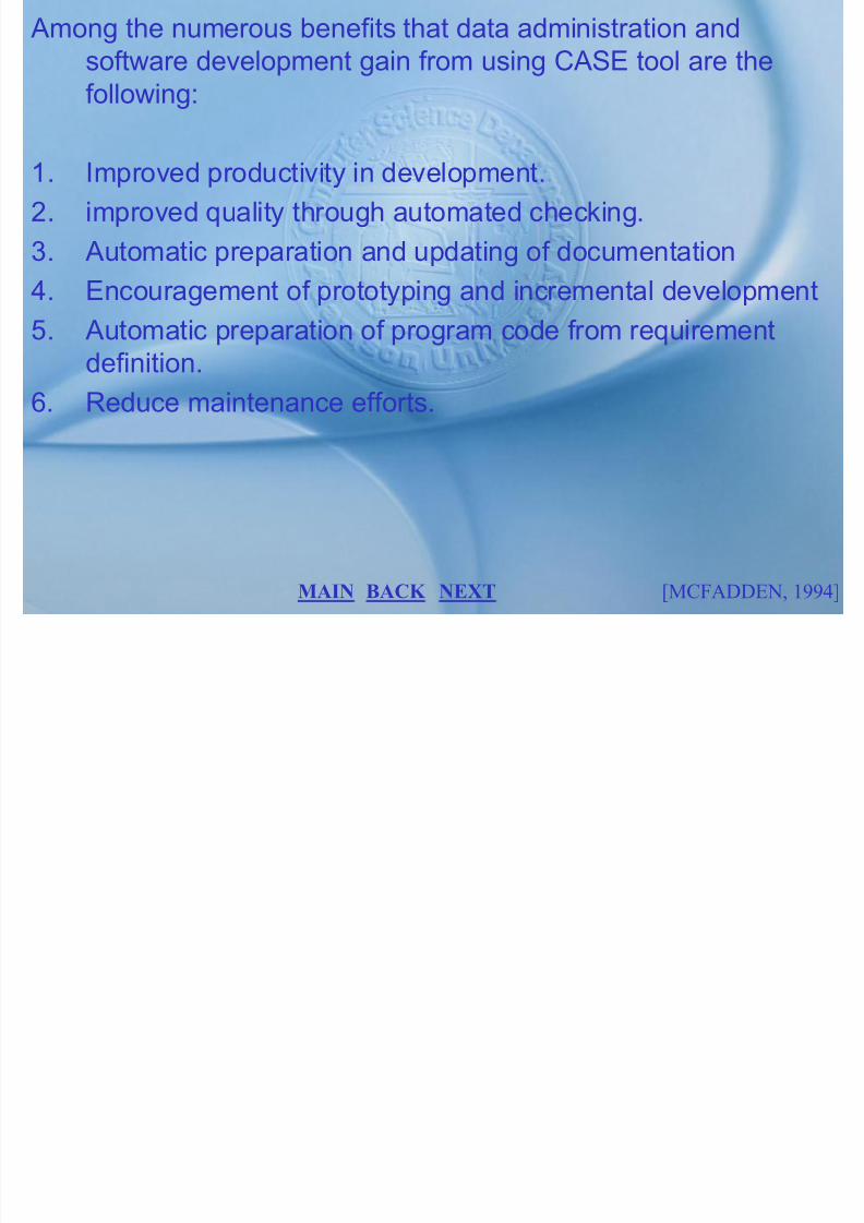
7/27/2019 MELJUN CORTES SYSTEM & ERD DBMS
http://slidepdf.com/reader/full/meljun-cortes-system-erd-dbms 244/396
y
2. improved quality through automated checking.
3. Automatic preparation and updating of documentation
4. Encouragement of prototyping and incremental development
5. Automatic preparation of program code from requirementdefinition.
6. Reduce maintenance efforts.
BACK NEXT [MCFADDEN, 1994]MAIN

7/27/2019 MELJUN CORTES SYSTEM & ERD DBMS
http://slidepdf.com/reader/full/meljun-cortes-system-erd-dbms 245/396
The major component of a full-function DBMS are shown inthis figure, and a brief description of each of these componentfollows.
DBMS E i
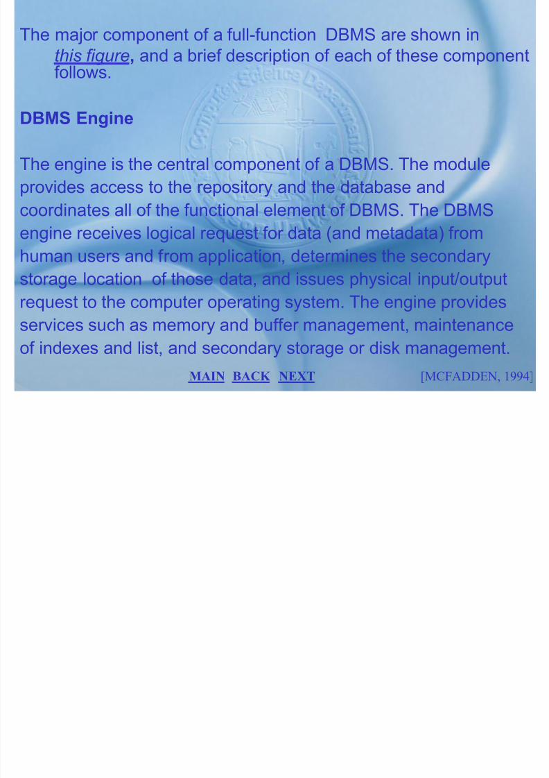
7/27/2019 MELJUN CORTES SYSTEM & ERD DBMS
http://slidepdf.com/reader/full/meljun-cortes-system-erd-dbms 246/396
DBMS Engine
The engine is the central component of a DBMS. The module
provides access to the repository and the database and
coordinates all of the functional element of DBMS. The DBMSengine receives logical request for data (and metadata) from
human users and from application, determines the secondary
storage location of those data, and issues physical input/output
request to the computer operating system. The engine providesservices such as memory and buffer management, maintenance
of indexes and list, and secondary storage or disk management.
BACK NEXT [MCFADDEN, 1994]MAIN

7/27/2019 MELJUN CORTES SYSTEM & ERD DBMS
http://slidepdf.com/reader/full/meljun-cortes-system-erd-dbms 247/396
Performance Management System
provides facilities to optimize (or at least improve) DBMSperformance two of its important functions follows:

7/27/2019 MELJUN CORTES SYSTEM & ERD DBMS
http://slidepdf.com/reader/full/meljun-cortes-system-erd-dbms 248/396
1. Query optimization: Structuring SQL queries ( or other formsof user queries) to minimize response times.
2. DBMS reorganization: Maintaining statistics on database
usage and taking (or recommending) actions such asdatabase reorganization, creating indexes, and so on toimprove DBMS performance.
[MCFADDEN, 1994]BACK NEXT MAIN
Data Integrity Management Subsystem
provides facilities for managing the integrity of data in thedatabase and the integrity of metadata in the repository.

7/27/2019 MELJUN CORTES SYSTEM & ERD DBMS
http://slidepdf.com/reader/full/meljun-cortes-system-erd-dbms 249/396
There are three important functions:
1. Intrarecords integrity: Enforcing constraints on data item
values and types within each record in the database.2. Referential Integrity: Enforcing the validity of the reference
between records in the database.
3. Concurrency Control: Assuming the validity of the database
updates when multiple users to access the database.
[MCFADDEN, 1994]BACK NEXT MAIN
Backup and Recovery Subsystem
provides facilities for logging transactions and databasechanges, periodically making backup copies of the database,and recovering the database in the event of some type of

7/27/2019 MELJUN CORTES SYSTEM & ERD DBMS
http://slidepdf.com/reader/full/meljun-cortes-system-erd-dbms 250/396
failure.
Application Development Subsystem
provides facilities that allows users and /or programmer todevelop complete database application. It includes CASEtools as well as facilities such as screen generators andreport generators.
[MCFADDEN, 1994]BACK NEXT MAIN
Security Management Subsystem
provides facilities to protect and control access to thedatabase and repository.

7/27/2019 MELJUN CORTES SYSTEM & ERD DBMS
http://slidepdf.com/reader/full/meljun-cortes-system-erd-dbms 251/396
[MCFADDEN, 1994]BACK NEXT MAIN
Concurrency Control
Database are shared resources. We must expect and plan for the
Lik lih d th t l ill tt t t d

7/27/2019 MELJUN CORTES SYSTEM & ERD DBMS
http://slidepdf.com/reader/full/meljun-cortes-system-erd-dbms 252/396
Likelihood that several user will attempt to access andmanipulate data at the same time. With concurrency processinginvolve updates, a database without concurrency control will be
compromised due to interference between users. There two
basic approach to concurrency control: a pessimisticapproaches (involving locking) and an optimistic approach(involving versioning).
[MCFADDEN, 1994]BACK NEXT MAIN
The problem of lost update
The most common problem that is encountered when multiple
users attempt to update a database without adequateconcurrent control is that of lost updates.

7/27/2019 MELJUN CORTES SYSTEM & ERD DBMS
http://slidepdf.com/reader/full/meljun-cortes-system-erd-dbms 253/396
Locking Mechanism
Locking mechanism are the most common type of concurrency
control mechanism. With locking, any data that is retrieved by auser for updating must be lock, or denied to other users, untilthe update is completed (or absorbed). Locking data is muchlike checking a book out of the library—it is unavailable to
others until the borrower returns it.
[MCFADDEN, 1994]BACK NEXT MAIN
Locking level
An important consideration in implementing concurrency
control is choosing the locking level. The locking level also
known as granularity is the extent of the database resource
th t i i l d d ith h l k M t i l d t

7/27/2019 MELJUN CORTES SYSTEM & ERD DBMS
http://slidepdf.com/reader/full/meljun-cortes-system-erd-dbms 254/396
that is included with each lock. Most commercial product
implement lock at one of the following levels:
1. Database. The entire database is locked and becomesunavailable to other user. This level has limited application,such as during a backup of the entire database.
2. Table. The entire table containing a requested record islocked. This level is appropriate mainly for bulk updates that
will update the entire table, such as giving all employees a 5%raise.
[MCFADDEN, 1994]BACK NEXT MAIN
3. Block or page. The physical storage block (or page)containing a requested record is blocked. This level generallynot desirable, since a page may contain records of more thanone types.
4. Record level. Only the requested records (or rows) is blocked.
Thi i th t l i l t d l ki l l ll

7/27/2019 MELJUN CORTES SYSTEM & ERD DBMS
http://slidepdf.com/reader/full/meljun-cortes-system-erd-dbms 255/396
This is the most commonly implemented locking level; allother records are available to other users. It does imposesome overhead at run time when several records are involvedin an update.
5. Field Level. Only the particular field (or column) in a requestedrecord is locked. This level may be appropriate when mostupdates affect only one or two field in record. For example, ininventory control application the quality-on-hand field changes
frequently, but other field (such as description and binlocation) are rarely updated. Field-level locks requireconsiderable overhead and are seldom used.
[MCFADDEN, 1994]BACK NEXT MAIN

7/27/2019 MELJUN CORTES SYSTEM & ERD DBMS
http://slidepdf.com/reader/full/meljun-cortes-system-erd-dbms 256/396
2. Exclusive lock
also called X locks, or write locks, prevent another transactionfrom reading and therefore updating a record until it isunlocked.
A t ti h ld l l i l k d h it i

7/27/2019 MELJUN CORTES SYSTEM & ERD DBMS
http://slidepdf.com/reader/full/meljun-cortes-system-erd-dbms 257/396
A transaction should place an exclusive lock on a record when it isabout to update that record. Placing an exclusive lock on arecord prevents another user from placing any type of lockthat record.
Deadlock
Locking solves the problem of erroneous updates but may lead toanother problem, called Deadlock : an impasse that results
when two or more transaction have locked a commonresource, and each must wait for the other to unlock thatresource.
[MCFADDEN, 1994]BACK NEXT MAIN
Managing Deadlock
There are two ways to resolve deadlocks: deadlock preventionand deadlock resolution. When Deadlock prevention isemployed, user program must lock all records they will require
at the beginning of the transaction

7/27/2019 MELJUN CORTES SYSTEM & ERD DBMS
http://slidepdf.com/reader/full/meljun-cortes-system-erd-dbms 258/396
at the beginning of the transaction.
Locking records in advance prevents deadlock. Unfortunately, it isoften difficult to predict in advance what record will be requiredto process a transaction. A typical program has manyprocessing parts and may call other program. As a resultdeadlock prevention is not often practical. The secondapproach is to allow deadlock to occur, but to buildmechanism into the DBMS for deleting and breaking the
deadlocks. Essentially, these deadlock resolution mechanismwork as follows.
[MCFADDEN, 1994]BACK NEXT MAIN
7/27/2019 MELJUN CORTES SYSTEM & ERD DBMS
http://slidepdf.com/reader/full/meljun-cortes-system-erd-dbms 259/396
Database Security
Database security is designed as protection of the database
against accidental or intentional lost destruction or misusef

7/27/2019 MELJUN CORTES SYSTEM & ERD DBMS
http://slidepdf.com/reader/full/meljun-cortes-system-erd-dbms 260/396
against accidental or intentional lost , destruction, or misuse.Data administration are the one responsible for developingoverall policies and procedures to protect databases.Database administration uses several facilities provided bythe data management software in carrying out these function.The most important security features of data managementsoftware follows:
1. Views or sub schemas, which restrict the user view of thedatabase.
2. Authorization rules, which identify user and restrict the action
they may take against the database.
BACK NEXT [MCFADDEN, 1994]MAIN
3. User-defined procedures, which define additional constraints
or limitations in using the database.4. Encryption procedures, which encode data in an
unrecognizable form5. Authentication schemes, which positively identify a person
attempting to gain access to the database

7/27/2019 MELJUN CORTES SYSTEM & ERD DBMS
http://slidepdf.com/reader/full/meljun-cortes-system-erd-dbms 261/396
View
A view is a subset of database that is presented to one or more
users. To illustrate, The PART and VENDOR relations are basetables that are part of a larger database. Suppose that a particular user requires a view that associates PART_NAME withVENDOR_NAME. We can provide this list by defining thefollowing view in SQL.
BACK NEXT [MCFADDEN, 1994]MAIN
CREATE VIEW PART_ VENDOR
AS SELECT PART_NAME, VENDOR _NAME,FROM PART, VENDORWHERE PART.VENDOR_NO = VENDOR.VENDOR_NO;
If the user enters this query:

7/27/2019 MELJUN CORTES SYSTEM & ERD DBMS
http://slidepdf.com/reader/full/meljun-cortes-system-erd-dbms 262/396
If the user enters this query:SELECT *
FROM PART_VENDORORDER BY PART_NAME
The following result will appear:PART_NAME VENDOR_NAMEGizmo ArtcraftThumzer choicetops
Whatsit ArtcraftWidget Deskmate
BACK NEXT [MCFADDEN, 1994]MAIN
Although view promote security by restricting user access to data,
they are not adequate security measures, becauseunauthorized person may gain knowledge of or access to aparticular views; all may have authority to read the data, butonly a restricted few may be authorized to update the data.Finally, with high-level query language, an unauthorized
person may gain access to data through simplei t ti A lt hi ti t d it

7/27/2019 MELJUN CORTES SYSTEM & ERD DBMS
http://slidepdf.com/reader/full/meljun-cortes-system-erd-dbms 263/396
person may gain access to data through simpleexperimentation. As a result, more sophisticated securitymeasures are normally required.
Authorization Rules
Authorization rules are controls incorporated in the datamanagement system that restrict access to the data. For example, a person who can supply a particular password maybe authorized to read any record in the database but cannot
necessarily modify any of those records.
BACK NEXT [MCFADDEN, 1994]MAIN
User-Defined Procedures
Some DBMS products provide user exit (or interface) that allowsystem designer or users to create their own user-defined
procedures for security in addition to the authorization rules

7/27/2019 MELJUN CORTES SYSTEM & ERD DBMS
http://slidepdf.com/reader/full/meljun-cortes-system-erd-dbms 264/396
procedures for security, in addition to the authorization ruleswe have just described. For example, a user procedure mightbe designed to provide positive user identification. Inattempting to log on to the computer, the user might berequired to supply a procedure name in addition to a simple
password. If a valid password and procedure name aresupplied, the system then call the procedure, which asks theuser a series of questions whose answer should be knownonly to that password holder (such as mother‘s maidenname).
BACK NEXT [MCFADDEN, 1994]MAIN
Encryption
is coding of data so that they cannot be read by humans.
For highly sensitive data (such as company financial data ), data
encryption can be used.

7/27/2019 MELJUN CORTES SYSTEM & ERD DBMS
http://slidepdf.com/reader/full/meljun-cortes-system-erd-dbms 265/396
For example, encryption is commonly use in electronic fundtransfer (EFT) system. Other DBMS product provides exitsthat allow users to code their own encryption routines. Anysystem that provides encryption facilities must also provide
complementary routines for decoding the data.
Authentication Schemes
A long-standing problem in computer circles is now to positivelyidentify persons who are trying to gain access to a computer or its resources.
BACK NEXT [MCFADDEN, 1994]MAIN
Password cannot, of themselves, ensure the security
of a computer and its database, because they give noindication of who is trying to gain access. To circumvent thisproblem, the industry is developing devices and techniques topositively identify any prospective user. The most promisingof these appear to be biometric devices, which measures or
detect personal characteristic such as finger prints voice

7/27/2019 MELJUN CORTES SYSTEM & ERD DBMS
http://slidepdf.com/reader/full/meljun-cortes-system-erd-dbms 266/396
detect personal characteristic such as finger prints, voiceprints, retina prints and signature dynamics.
To implement this approach, several companies have developeda smart card — a thin plastic card the size of a credit card,with an embedded microprocessor. An individual‘s unique
biometric data (such as fingerprints) are stored permanentlyon the card. To access the computer, the user insert the cardinto a reader device (a biometric device) that reads theperson‘s fingerprints (or other characteristic) The actualbiometric data are compared with the stored data, and the
must match for the user to gain computer access. A lost or stolen card would be useless to another person, since thebiometric data would not match.
BACK NEXT [MCFADDEN, 1994]MAIN
Database Recovery
Data recovery is data administration‘s response to Murphy‘s law.
Inevitably, database are damage or lost because of some system
problem that may be caused by human error hardware failure

7/27/2019 MELJUN CORTES SYSTEM & ERD DBMS
http://slidepdf.com/reader/full/meljun-cortes-system-erd-dbms 267/396
problem that may be caused by human error, hardware failure,incorrect or valid data, program errors, computer viruses, or natural catastrophes. Since the organization depends so heavilyon its database, the database management system must provide
mechanisms for restoring a database quickly and accurately after loss or damage.
Basic Recovery Facilities
A database management system should provide four basic
facilities for the backup and recovery of a database:
BACK NEXT [MCFADDEN, 1994]MAIN
1. Backup facilities, which provide periodic backup copies of theentire database
2. Journalizing Facilities, which maintain an audit trail of transaction and database changes.
3. A checkpoint facility, by which the DBMS periodicallysuspends all processing and synchronizes its files and
7/27/2019 MELJUN CORTES SYSTEM & ERD DBMS
http://slidepdf.com/reader/full/meljun-cortes-system-erd-dbms 268/396
suspends all processing and synchronizes its files and journals.
4. A. Recovery manager, which allows the DBMS to restore thedatabase to a correct condition and restart processing
transactions.
Backup Facilities
The DBMS should provides backup facilities that produce abackup copy of the entire database. Typically, a backup copy isproduced at least once per day. The copy should be stored in a
BACK NEXT [MCFADDEN, 1994]MAIN
secured location where it is protected from lost or damage. The
backup copy is used to restore the database in the event of catastrophic or damage.
Journalizing Facilities
A DBMS must provide Journalizing Facilities to produce an audit

7/27/2019 MELJUN CORTES SYSTEM & ERD DBMS
http://slidepdf.com/reader/full/meljun-cortes-system-erd-dbms 269/396
A DBMS must provide Journalizing Facilities to produce an audittrail of transaction and database changes.
There are two basic journal: first, there is the transaction log ,
which contains a record of the essential data transaction thatis processed against the database.
The second kind of log Is the database change log , whichcontains before-and after-images of records that have been
modified by transactions. A before-image is simply a copy of a record before it has been modified, and an after-image is acopy of the same record after it has been modified.
BACK NEXT [MCFADDEN, 1994]MAIN
Checkpoint Facility
A checkpoint facility in a DBMS periodically refuses to accept anynew transactions. All transaction in progress are completed,and journal files are brought up to date. At this point, thesystem is in a quite state and the database and transaction
log are synchronized

7/27/2019 MELJUN CORTES SYSTEM & ERD DBMS
http://slidepdf.com/reader/full/meljun-cortes-system-erd-dbms 270/396
log are synchronized.
The DBMS write a special record (called a checkpoint record) tothe log file. The checkpoint records contains informationnecessary to restart the system.
Recovery Manager
The recovery manager is a module of database that restore the
database to the correct condition when a failure occurs, andresume processing user request. The type of restart useddepends on the nature of the failure.
BACK NEXT [MCFADDEN, 1994]MAIN
Recovery and Restart Procedures
The type of recovery of procedure that is used in the givensituation depends on the nature of the failure, the sophistication of the DBMS recovery facilities, and operational policies and
procedures

7/27/2019 MELJUN CORTES SYSTEM & ERD DBMS
http://slidepdf.com/reader/full/meljun-cortes-system-erd-dbms 271/396
procedures.
The following is a discussion of the techniques that are mostfrequently used:
Restore and Rerun
The techniques involve the reprocessing the day‘s transactionagainst the backup copy of the database. The most recent
copy of database is mounted and all transaction that haveoccurred since the copy are rerun.
BACK NEXT [MCFADDEN, 1994]MAIN
The advantages of restore/rerun is its simplicity. The DBMS doesnot need to create a database change journal, and no specialrestart procedures are required.
Transaction Integrity

7/27/2019 MELJUN CORTES SYSTEM & ERD DBMS
http://slidepdf.com/reader/full/meljun-cortes-system-erd-dbms 272/396
Transaction Integrity
The database is updated by processing transaction that result in
changes to one or more database records. If an error occurs
during the process of transaction, the database may be
compromised, and some form of database recovery is required.
Thus, to understand database recovery we must first understand
the concept of transaction integrity. A business transaction is a
sequence of steps that constitute some well-defined business
activity. Example the business transaction are ―admit patient‖ and
BACK NEXT [MCFADDEN, 1994]MAIN
―Enter customer Order‖. Normally a business transaction requires
several action against the database. For example, consider thetransaction ―Enter Customer Order‖. When the new customer
order is entered, the following steps may be performed by anapplication program.
1 I t d d t (k b )

7/27/2019 MELJUN CORTES SYSTEM & ERD DBMS
http://slidepdf.com/reader/full/meljun-cortes-system-erd-dbms 273/396
1. Input order data (key by user).2. Read CUSTOMER record (or insert record if a new
customer).3. Accept or reject the order (if balance due plus order amount
does not exceed credit limit, accept the order; otherwise,reject it)
4. If the order is accepted: Increase balance due by Order Amount. Store the update CUSTOMER record. Insert theaccepted ORDER record in the database.
BACK NEXT [MCFADDEN, 1994]MAIN
Backward Recovery
With backward recovery (also called rollback ), the DBMS backs
out of or undoes unwanted changes to the database. As this
figure shows before-image of the records that have beenchanged are applied to the database As a result the

7/27/2019 MELJUN CORTES SYSTEM & ERD DBMS
http://slidepdf.com/reader/full/meljun-cortes-system-erd-dbms 274/396
figure shows, before image of the records that have beenchanged are applied to the database. As a result, thedatabase is returned to an earlier state; the unwantedchanges are eliminated.
Backward recovery is used to reverse the changes by transaction
that have aborted, or terminated abnormally. To illustrate theneed for backward recovery (or UNDO), suppose that abanking transaction will transfer $100 in funds from theaccount for customer A to the account for customer B.
BACK NEXT [MCFADDEN, 1994]MAIN
These steps are performed:
• The program reads the record for customer A and subtracts$100 from the account balance.
• The program then reads the record for customer B and adds$100 to the account balance.

7/27/2019 MELJUN CORTES SYSTEM & ERD DBMS
http://slidepdf.com/reader/full/meljun-cortes-system-erd-dbms 275/396
Now the program writes the updated record for customer A to thedatabase. However, in attempting to write the record for customer B, the program encounters an error condition (such as disk fault)
and cannot write the record. Now the database is inconsistent— record A has been updated but record B has not—and thetransaction must be aborted. An UNDO command will cause therecovery manager to apply the before-image for record A to
restore the account balance to its original value (the recoverymanager may then restart the transaction and make another attempt).
BACK NEXT [MCFADDEN, 1994]MAIN
Forward Recovery
also called rollforward. DBMS starts with an earlier copy of the database. By applying after-image (the results of goodtransactions), the database is quickly moved forward to alater state. Forward recovery is much faster and more
7/27/2019 MELJUN CORTES SYSTEM & ERD DBMS
http://slidepdf.com/reader/full/meljun-cortes-system-erd-dbms 276/396
later state. Forward recovery is much faster and moreaccurate than restore/ rerun, for the following reasons:
1. The time-consuming logic of reprocessing each transactiondoes not have to be repeated.
2. Only the most recent after-images need to be applied. Adatabase record may have a series of after-images (as aresult of a sequence of updates), but only the recent, ―good‖
after-image is required for rollforward.
BACK NEXT [MCFADDEN, 1994]MAIN
The problem of different sequencing of transaction is avoided,
since the results of applying the transactions (rather than thetransactions themselves) are used.
Types of Database Failure
A ide ariet of fail res can occ r in processing a database
7/27/2019 MELJUN CORTES SYSTEM & ERD DBMS
http://slidepdf.com/reader/full/meljun-cortes-system-erd-dbms 277/396
A wide variety of failures can occur in processing a database,ranging from the input of an incorrect data value to complete lossor destruction of database. These are the four most commontypes of errors:
Aborted transactions terminates abnormally. some reasons for this type of failure are human error, input of invalid data, hardwarefailure, and deadlock.
BACK NEXT [MCFADDEN, 1994]MAIN
Incorrect data
a more complex situation arises when database has beenupdated with incorrect, but valid, data. For example, anincorrect grade may recorded for a student, or an incorrectamount input for a customer payment. When incorrect data
have been introduced, the database may be recovered in oneof the following ways:

7/27/2019 MELJUN CORTES SYSTEM & ERD DBMS
http://slidepdf.com/reader/full/meljun-cortes-system-erd-dbms 278/396
have been introduced, the database may be recovered in oneof the following ways:
1. If the error is discovered soon enough, backward recoverymay be used.
2. If only a few errors have occurred, a series of compensatingtransactions may be introduced through human interventionto correct the errors.
3. If the first two measures are not feasible, it may be necessaryto restart from the most recent checkpoint before the error
occurred.
BACK NEXT [MCFADDEN, 1994]MAIN
System failure
In a system failure, some component of the system fails but thedatabase is not damaged. some cause of system failure arepower loss, operator error, loss of communicationstransmission, and system software failure.

7/27/2019 MELJUN CORTES SYSTEM & ERD DBMS
http://slidepdf.com/reader/full/meljun-cortes-system-erd-dbms 279/396
Database Destruction
The database itself is lost or destroyed, or cannot be read. A
typical cause of database destruction is a disk drive failure (or head crash).
BACK NEXT [MCFADDEN, 1994]MAIN
MAIN MENU

7/27/2019 MELJUN CORTES SYSTEM & ERD DBMS
http://slidepdf.com/reader/full/meljun-cortes-system-erd-dbms 280/396
PRELIM FINALS
MIDTERM
LABORATORY COURSE SYLLABUS

7/27/2019 MELJUN CORTES SYSTEM & ERD DBMS
http://slidepdf.com/reader/full/meljun-cortes-system-erd-dbms 281/396
exit
Thanks for using this CATT for DBMS
Christopher, Cherlene, Julie, Gef, Jo

7/27/2019 MELJUN CORTES SYSTEM & ERD DBMS
http://slidepdf.com/reader/full/meljun-cortes-system-erd-dbms 282/396
exit

7/27/2019 MELJUN CORTES SYSTEM & ERD DBMS
http://slidepdf.com/reader/full/meljun-cortes-system-erd-dbms 283/396
exit
Click to enter again
7/27/2019 MELJUN CORTES SYSTEM & ERD DBMS
http://slidepdf.com/reader/full/meljun-cortes-system-erd-dbms 284/396
exit
Leader: Christopher Iresare
Animation and concept: Jo B. FranciscoResearch: Geffrey Fabian
Documentation: Julie Atienza
Slide design: Cherlene Galang
Adamson University

7/27/2019 MELJUN CORTES SYSTEM & ERD DBMS
http://slidepdf.com/reader/full/meljun-cortes-system-erd-dbms 285/396
EXIT
NEXT
College of Sciences
Department of Computer Science
Course Syllabus
I. COURSE DESCRIPTION
The course provides students with an introduction to

7/27/2019 MELJUN CORTES SYSTEM & ERD DBMS
http://slidepdf.com/reader/full/meljun-cortes-system-erd-dbms 286/396
pdatabase management. It emphasizes on providingstudents with concepts and notations for modelingorganizational data and designing databases.
BACK NEXT [MCFADDEN, 1994]MAIN
II. COURSE OBJECTIVES
At the end of the semester, the students are expected to:
1. General Objectives

7/27/2019 MELJUN CORTES SYSTEM & ERD DBMS
http://slidepdf.com/reader/full/meljun-cortes-system-erd-dbms 287/396
1.1 Define terms associated with database and databasemanagement.
1.2 Define the different steps in developing database andapplication.
1.3 Discuss the different concept and notations used inmodeling data and in database designs.
[MCFADDEN, 1994]BACK NEXT MAIN
V. COURSE REQUIREMENTS
Assignments/Excercises/Boardwork/RecitationMachine problems/Case studyQuizzesTerm Examination
VI. REFERENCES

7/27/2019 MELJUN CORTES SYSTEM & ERD DBMS
http://slidepdf.com/reader/full/meljun-cortes-system-erd-dbms 288/396
Modern Database Management 4th Ed. By Mc Fadden An Introduction to Database Systems by DateMastering Foxpro 2.6 by Charles Siegel
VII. GRADING SYSTEM
Examination (Prelim, Midterm, Final) 40%Class Standing
Quizzes Recitations/Seatwork/Boardwork 60% Assignment Case study 100%
BACK NEXT MAIN
PRELIM
Objectives
1 Known the basic
Database Environment
• Information Resource

7/27/2019 MELJUN CORTES SYSTEM & ERD DBMS
http://slidepdf.com/reader/full/meljun-cortes-system-erd-dbms 289/396
1. Known the basicprinciples of Information ResourceManagement.
2. Contrast centralizedand distributeddatabase.
3. Describe the major
characteristic andshortcoming of the
Information Resource
Management
• Data vs. Information
• Databases and it‘stypes
• File Processing System
• Database Approach
• Components of theDatabase Environment
BACK NEXT
EXIT
PRELIM
processing system.
4. Describe the major advantages of the
Database Development
Process

7/27/2019 MELJUN CORTES SYSTEM & ERD DBMS
http://slidepdf.com/reader/full/meljun-cortes-system-erd-dbms 290/396
gdatabase processingapproach compared tothe traditional one.
5. Describe the major component of adatabase environmentand identify the step in
the development of database.
• Information Systems Architecture
• Information EngineeringMethodology
• Planning
• Analysis and Design
• Strategic informationsystems Planning
BACK NEXT
EXIT
PRELIM
6. Describe the four stages of information
engineered and the
• Role of a repository
• Pitfalls in strategicIS planning

7/27/2019 MELJUN CORTES SYSTEM & ERD DBMS
http://slidepdf.com/reader/full/meljun-cortes-system-erd-dbms 291/396
purpose of eachstage.
7. Describe the major
component of anenterprise model.
gIS planning
BACK NEXT
EXIT
MIDTERM
Objectives
At the end of the topic the
E.R. Diagram
• Concepts

7/27/2019 MELJUN CORTES SYSTEM & ERD DBMS
http://slidepdf.com/reader/full/meljun-cortes-system-erd-dbms 292/396
At the end of the topic the
student should be able to:
1. Define the followingterms regarding E.R.diagramming.
2. Draw the E.R. diagram
to represent commonbusiness problems.
Concepts
• Entities
• Attributes
• Relationships • Multi-valued Attributes
• Generalization
BACK NEXT
EXIT
MIDTERM
3. Distinguish betweenunary, binary, ternary
relationship and givean example of each
Normalization
• Concepts

7/27/2019 MELJUN CORTES SYSTEM & ERD DBMS
http://slidepdf.com/reader/full/meljun-cortes-system-erd-dbms 293/396
an example of each.
4. Model multi-valuedattributes andrepeating groups in
E.R. diagram.5. Give a concise
definition for each of the following
normalizationprocesses.
Co cep s
• Steps
• Basic Normal Form
• Additional Normal Form
BACK NEXT
EXIT
FINALS
Objectives
At the end of the topic the
Physical Design
• Physical Design

7/27/2019 MELJUN CORTES SYSTEM & ERD DBMS
http://slidepdf.com/reader/full/meljun-cortes-system-erd-dbms 294/396
students must be able to:
1. Be familiar with the
concept and processof physical databasedesign.
2. Use SQL datadefinition languagecommands in writingor performing queries.
y gProcess
• Data volume and Usage Analysis
• Data DistributionStrategy
• File Organization
• Indexes
BACK NEXT
EXIT
FINALS
3. Define key terms andmajor functions on
data administration.
Relational Database
Implementation
7/27/2019 MELJUN CORTES SYSTEM & ERD DBMS
http://slidepdf.com/reader/full/meljun-cortes-system-erd-dbms 295/396
4. Describe the role of aninformation repositoryand how it is used by
data administration.5. Compare the
optimistic andpessimistic system of
concurrency control.
• Relational dataDefinition in SQL
• Data Retrieval andManipulation
• Multiple TableOperations
BACK NEXT
EXIT
FINALS
6. Describe the problemof database security
and data recovery andth t h i i
Data Administration
• Data Administration

7/27/2019 MELJUN CORTES SYSTEM & ERD DBMS
http://slidepdf.com/reader/full/meljun-cortes-system-erd-dbms 296/396
the techniques indealing with theseproblems.
Functions
• Data AdministrationTools
• Concurrency Control
• Database Security
• Database Recovery
BACK NEXT
EXIT
MAIN MENU

7/27/2019 MELJUN CORTES SYSTEM & ERD DBMS
http://slidepdf.com/reader/full/meljun-cortes-system-erd-dbms 297/396
PRELIM FINALS
MIDTERM
LABORATORY COURSE SYLLABUS
LABORATORY

7/27/2019 MELJUN CORTES SYSTEM & ERD DBMS
http://slidepdf.com/reader/full/meljun-cortes-system-erd-dbms 298/396
EXIT
NEXT
Microsoft Access
Database Application with MS Access
Microsoft Access is a relational database program that providesyou the following:
Li itl t t f i f ti

7/27/2019 MELJUN CORTES SYSTEM & ERD DBMS
http://slidepdf.com/reader/full/meljun-cortes-system-erd-dbms 299/396
• Limitless storage amount of information.• Organized information in a manner that it makes sense on
how you work
• Create forms for easier ways to enter information• Produce meaningful and insightful reports that can be
combine data with other applications.
[DOMINGUEZ, ZIPAGAN, 2000]BACK NEXT MAIN
Starting MS Access
How to start MS Access
1. Click Start button

7/27/2019 MELJUN CORTES SYSTEM & ERD DBMS
http://slidepdf.com/reader/full/meljun-cortes-system-erd-dbms 300/396
2. Select Programs3. Choose and click Microsoft Access
How to create a Database
1. Choose File, then Click new2. Click the New button from the toolbar
3. Type your database name in the open filename dialog box.4. Click create button.
[DOMINGUEZ, ZIPAGAN, 2000]BACK NEXT MAIN
How create a table using design view
1. In the database window click, Tables tab.
2. Choose New, then click the design view option. In the design
view dialog box, create details of your table.
3. Click OK

7/27/2019 MELJUN CORTES SYSTEM & ERD DBMS
http://slidepdf.com/reader/full/meljun-cortes-system-erd-dbms 301/396
[DOMINGUEZ, ZIPAGAN, 2000]BACK NEXT MAIN
4. In the filename column of the design view, enter the first
field name

7/27/2019 MELJUN CORTES SYSTEM & ERD DBMS
http://slidepdf.com/reader/full/meljun-cortes-system-erd-dbms 302/396
[DOMINGUEZ, ZIPAGAN, 2000]BACK NEXT MAIN
5. Press the Tab or the enter key to move the insertion point
to the next column which is data type.
6. Click the down arrow button to view the list of data typesavailable for defining a field.
7. Press the tab key again to move the intersection point to

7/27/2019 MELJUN CORTES SYSTEM & ERD DBMS
http://slidepdf.com/reader/full/meljun-cortes-system-erd-dbms 303/396
the next column.
8. Define all the fields for your table. Click the table view
button from the toolbar.
9. Save table.
[DOMINGUEZ, ZIPAGAN, 2000]BACK NEXT MAIN
Defining a primary key
You need to define a primary key to view record in a form.
How to create a primary key
1. Choose the field you want to set as primary key

7/27/2019 MELJUN CORTES SYSTEM & ERD DBMS
http://slidepdf.com/reader/full/meljun-cortes-system-erd-dbms 304/396
2. From the toolbar, click the primary key, or select the editmenu to click the primary key. A key symbol appears to
the left of the field name you had set as the primary key.
[DOMINGUEZ, ZIPAGAN, 2000]BACK NEXT MAIN
Ways to customize field properties
You can easily customize your field‘s data, either printed or
displayed on the screen. You can automatically add two decimalplaces to the entered number or format using currency sign or change the field size, or change the date/time and use other formatting commands of Access.
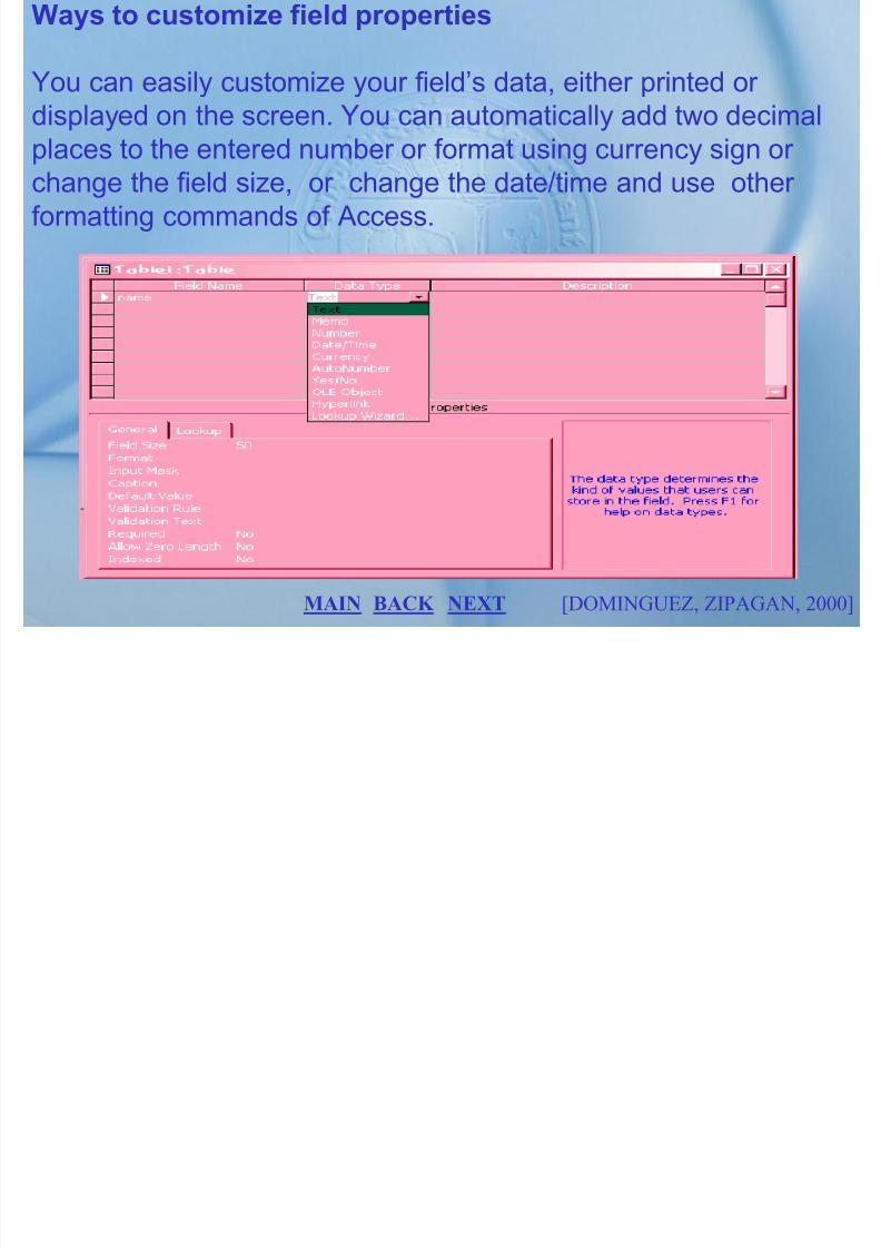
7/27/2019 MELJUN CORTES SYSTEM & ERD DBMS
http://slidepdf.com/reader/full/meljun-cortes-system-erd-dbms 305/396
[DOMINGUEZ, ZIPAGAN, 2000]BACK NEXT MAIN
Ways to create Relationship using tools
1. Click the tools menu2. Select the Relationship command.3. Click the show up table button if the table for which you
want to define does not show up.4. The show table button list is highlighted. Click the add

7/27/2019 MELJUN CORTES SYSTEM & ERD DBMS
http://slidepdf.com/reader/full/meljun-cortes-system-erd-dbms 306/396
button.5. Click on create button, to create a line between these two
tables.
[DOMINGUEZ, ZIPAGAN, 2000]BACK NEXT MAIN
Queries
A query is considered as the brain of a relational databasesystem enabling the user to view information about the records
that can be attached to another database.

7/27/2019 MELJUN CORTES SYSTEM & ERD DBMS
http://slidepdf.com/reader/full/meljun-cortes-system-erd-dbms 307/396
Uses of queries
• Used to search specific records based on the criteria given• Performs the required calculation of data• Create graphics based on query• It is used to view, change, and analyze data contained in those
records in different ways
• Simple queries involve sorting all the records on one table byone field.
[DOMINGUEZ, ZIPAGAN, 2000]BACK NEXT MAIN
The most used query type
Select query
Where you can gather or select records in the table and view theinformation in different ways. This query allows you to edit thedata in the table and make any changes in the dynaset.

7/27/2019 MELJUN CORTES SYSTEM & ERD DBMS
http://slidepdf.com/reader/full/meljun-cortes-system-erd-dbms 308/396
[DOMINGUEZ, ZIPAGAN, 2000]
Sample
Select
query
BACK NEXT MAIN
Creating and Using Simple Forms
What is a Form
A form looks like a fill-in-the blanks sheet that appears on the

7/27/2019 MELJUN CORTES SYSTEM & ERD DBMS
http://slidepdf.com/reader/full/meljun-cortes-system-erd-dbms 309/396
screen used to view one data, edit existing records, enter andprint new individual records. Access makes the job of creatingand modifying forms quick and easy. These tools are:
• Form wizard• Auto forms• Form templates
• Spell checking
[DOMINGUEZ, ZIPAGAN, 2000]BACK NEXT MAIN
What is a Subform?
A subform is a form that is displayed on another form.
2 ways to add a subform
• Use Subform/Subreport controlB d i th f th bf f th f t b f
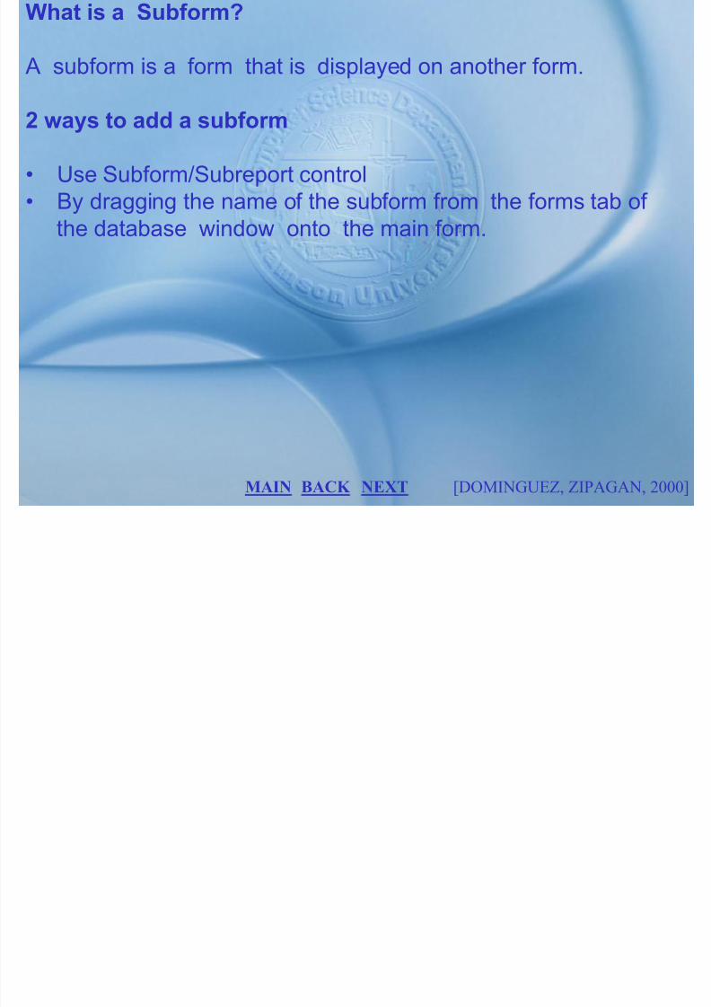
7/27/2019 MELJUN CORTES SYSTEM & ERD DBMS
http://slidepdf.com/reader/full/meljun-cortes-system-erd-dbms 310/396
• By dragging the name of the subform from the forms tab of the database window onto the main form.
[DOMINGUEZ, ZIPAGAN, 2000]BACK NEXT MAIN
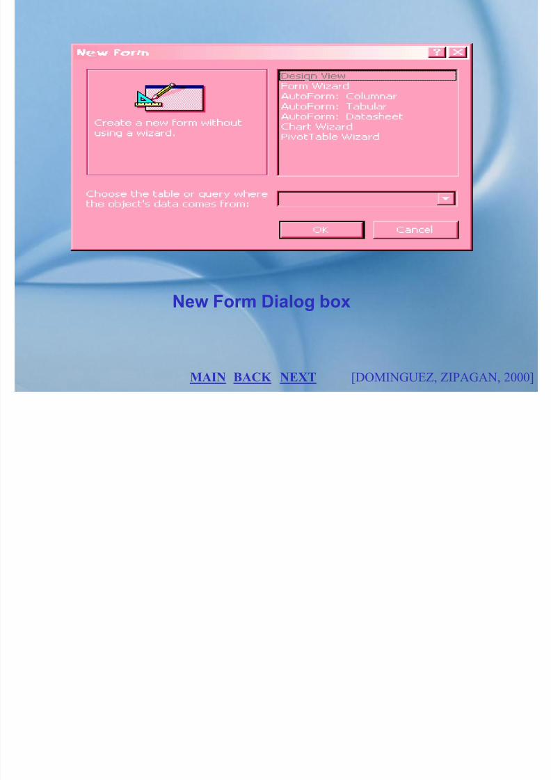
7/27/2019 MELJUN CORTES SYSTEM & ERD DBMS
http://slidepdf.com/reader/full/meljun-cortes-system-erd-dbms 311/396
[DOMINGUEZ, ZIPAGAN, 2000]
New Form Dialog box
BACK NEXT MAIN

7/27/2019 MELJUN CORTES SYSTEM & ERD DBMS
http://slidepdf.com/reader/full/meljun-cortes-system-erd-dbms 312/396
[DOMINGUEZ, ZIPAGAN, 2000]
Forms tab of database window
BACK NEXT MAIN
How to create a form wizard
1. Click on the Forms tab, click the new button.
2. From the New form dialog box, select form wizard.

7/27/2019 MELJUN CORTES SYSTEM & ERD DBMS
http://slidepdf.com/reader/full/meljun-cortes-system-erd-dbms 313/396
[DOMINGUEZ, ZIPAGAN, 2000]
New Normal form dialog box
BACK NEXT MAIN

7/27/2019 MELJUN CORTES SYSTEM & ERD DBMS
http://slidepdf.com/reader/full/meljun-cortes-system-erd-dbms 314/396
[DOMINGUEZ, ZIPAGAN, 2000]
Auto forms
BACK NEXT MAIN
3. You must select one to continue using form wizard

7/27/2019 MELJUN CORTES SYSTEM & ERD DBMS
http://slidepdf.com/reader/full/meljun-cortes-system-erd-dbms 315/396
[DOMINGUEZ, ZIPAGAN, 2000]
Backgrounds available to choose from
BACK NEXT MAIN
4. Click OK button.
5. Determine how the data in the form is viewed6. Choose any from ten different background options.
7. Type the name of the form.
8. Click the finish button to create and save the forms.

7/27/2019 MELJUN CORTES SYSTEM & ERD DBMS
http://slidepdf.com/reader/full/meljun-cortes-system-erd-dbms 316/396
[DOMINGUEZ, ZIPAGAN, 2000]BACK NEXT MAIN
MAIN MENU
PRELIM FINALS

7/27/2019 MELJUN CORTES SYSTEM & ERD DBMS
http://slidepdf.com/reader/full/meljun-cortes-system-erd-dbms 317/396
PRELIM FINALS
MIDTERM
LABORATORY COURSE SYLLABUS
Class Roster
Course: B.S. CPSCI Semester: 1st
Section: 25234

7/27/2019 MELJUN CORTES SYSTEM & ERD DBMS
http://slidepdf.com/reader/full/meljun-cortes-system-erd-dbms 318/396
Name ID Elective GPAJo. B. Francisco 9999912 Internet 1.5Julie Ann Atienza 9912989 C.S.A. 1.9
Geffrey Fabian 9923949 Microprocessor 2.1Christopher Iresare 9934780 Internet 3.0Cherlene Galang 9970431 M.I.S. 1.9Michael Autos 9999568 A.S.A.D 2.7
Data
EXIT
20%
25%
internet

7/27/2019 MELJUN CORTES SYSTEM & ERD DBMS
http://slidepdf.com/reader/full/meljun-cortes-system-erd-dbms 319/396
0%
5%
10%
15%
internet
C.S.A.
Microprocessor
M.I.S.
A.S.A.D.
Information
EXIT
Marketing
SalesProduct
Development
Management
Planning Control

7/27/2019 MELJUN CORTES SYSTEM & ERD DBMS
http://slidepdf.com/reader/full/meljun-cortes-system-erd-dbms 320/396
The concept of a shared corporate database
Materials
PurchasingRequirements
PlanningManufacturing
Scheduling Production
Accounting
Accounts
receivable
Accounts
Payable
Corporate
database
EXIT
The concepts of a Shared Corporate Database
In this vision, all of the various functional areas operate from the
Same set of shared data contained in the corporate database.
There is a standard set of data definitions, and a data adminis-
tration group is custodian of this corporate resource. The vision

7/27/2019 MELJUN CORTES SYSTEM & ERD DBMS
http://slidepdf.com/reader/full/meljun-cortes-system-erd-dbms 321/396
has proved difficult to achieve in practice, for a variety of reasons.
Databases in most organizations have evolved over a period of
time, often without a comprehensive plan to guide their development. The ease of use of contemporary database
software has encouraged end users to develop their own
database application, which often duplicate data already
contained in other applications. According to Daydov (1993), ―the
current state of database applications is characterized by the fact
BACK NEXT
that companies continue to deploy databases to meet isolated
application needs. The end result is more redundant, incompatible
data.‖ Nevertheless, the goal of shared databases is not valid but
essential for the successful organizations of the future.

7/27/2019 MELJUN CORTES SYSTEM & ERD DBMS
http://slidepdf.com/reader/full/meljun-cortes-system-erd-dbms 322/396
BACK EXIT

7/27/2019 MELJUN CORTES SYSTEM & ERD DBMS
http://slidepdf.com/reader/full/meljun-cortes-system-erd-dbms 323/396
Personal computer database
EXIT

7/27/2019 MELJUN CORTES SYSTEM & ERD DBMS
http://slidepdf.com/reader/full/meljun-cortes-system-erd-dbms 324/396
Central computer database
Central Computer
EXIT
Client

7/27/2019 MELJUN CORTES SYSTEM & ERD DBMS
http://slidepdf.com/reader/full/meljun-cortes-system-erd-dbms 325/396
Client/Server database
Client
Local area
network
EXIT
Databaseserver Client

7/27/2019 MELJUN CORTES SYSTEM & ERD DBMS
http://slidepdf.com/reader/full/meljun-cortes-system-erd-dbms 326/396
ClientRemote

7/27/2019 MELJUN CORTES SYSTEM & ERD DBMS
http://slidepdf.com/reader/full/meljun-cortes-system-erd-dbms 327/396
Heterogeneous (federated) database
Client
Computer
Remote
Computer
EXIT
Communicationsserver Client
Requirementsanalysis
Processdesign
Requirementsanalysis
Databasedesign

7/27/2019 MELJUN CORTES SYSTEM & ERD DBMS
http://slidepdf.com/reader/full/meljun-cortes-system-erd-dbms 328/396
Process-driven versus data-driven design
Process-driven
design
Data-driven
design
Data
design
Implementation
Process
design
Implementation
EXIT
Preliminary
enterprise
data model
ORDER
CUSTOMER
INVOICE
Places Bills
||||
||
Fulfills

7/27/2019 MELJUN CORTES SYSTEM & ERD DBMS
http://slidepdf.com/reader/full/meljun-cortes-system-erd-dbms 329/396
Enterprise data model of Pine Valley Furniture
Product
Raw material
||
work order | |
=
EXIT
Data
administrators
System
developers
End
users

7/27/2019 MELJUN CORTES SYSTEM & ERD DBMS
http://slidepdf.com/reader/full/meljun-cortes-system-erd-dbms 330/396
Components of the database environment
User
Interface
Database
Application
programs
CASE
tools
Repository DBMS
EXIT
Database
planning
Database
analysis
Growthand
change

7/27/2019 MELJUN CORTES SYSTEM & ERD DBMS
http://slidepdf.com/reader/full/meljun-cortes-system-erd-dbms 331/396
Stages in a database system life cycle
EXIT
Operation and
Maintenance
Database design
Database
implementation

7/27/2019 MELJUN CORTES SYSTEM & ERD DBMS
http://slidepdf.com/reader/full/meljun-cortes-system-erd-dbms 332/396
Functions of Data Administration
EXIT
PeopleTools
Repository
Information Repository
Dictionary System
Information repository
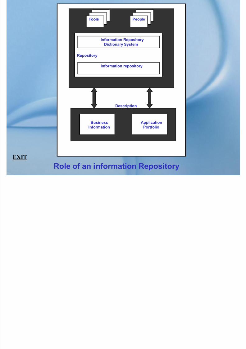
7/27/2019 MELJUN CORTES SYSTEM & ERD DBMS
http://slidepdf.com/reader/full/meljun-cortes-system-erd-dbms 333/396
Role of an information Repository
EXIT
Description
Business
Information
Application
Portfolio
Feasibility analysis
Requirements definition
Logical design
Realm of
upper-CASE
tools

7/27/2019 MELJUN CORTES SYSTEM & ERD DBMS
http://slidepdf.com/reader/full/meljun-cortes-system-erd-dbms 334/396
System development life cycle
EXIT
Physical design Prototyping
Programming and testing Successive approximation
Implementation
Maintenance
Realm of lower-
CASE tools
C1
CUSTOMER
Receipt
Customer request
Request tape
Billing info
RT1
RENT TAPE
TO
CUSTOMER
(a) Sample level 0 data flow diagram

7/27/2019 MELJUN CORTES SYSTEM & ERD DBMS
http://slidepdf.com/reader/full/meljun-cortes-system-erd-dbms 335/396
Case tools diagram
EXIT
INV RENTAL DATABASE
RT2
INQUIRY
AND
UPDATE
S1 SYSTEM
CONTROL
MANAGER
Overdue
notice and
charges
Sales and
rental History
Inventory and price
charges
Queries
and
reports
Inventory pricing
updates
NEXT
(b) Sample entity-relation diagram
CUSTOMER
CUSTOMER NO.
TITLES
TITLE

7/27/2019 MELJUN CORTES SYSTEM & ERD DBMS
http://slidepdf.com/reader/full/meljun-cortes-system-erd-dbms 336/396
Case tools diagram
EXIT
RentsHas
Many
TITLES
TITLE
HasMany
TITLES
TITLE
BACK
SystemDevelopment
Diagramming
Screen andreport painters
Repository andreports
Tools for drawing structured diagrams
and creating pictorial specifications.
Tools for prototyping the user interfaceand creating system specifications.
Facility for storing, reporting, andquerying all system information.
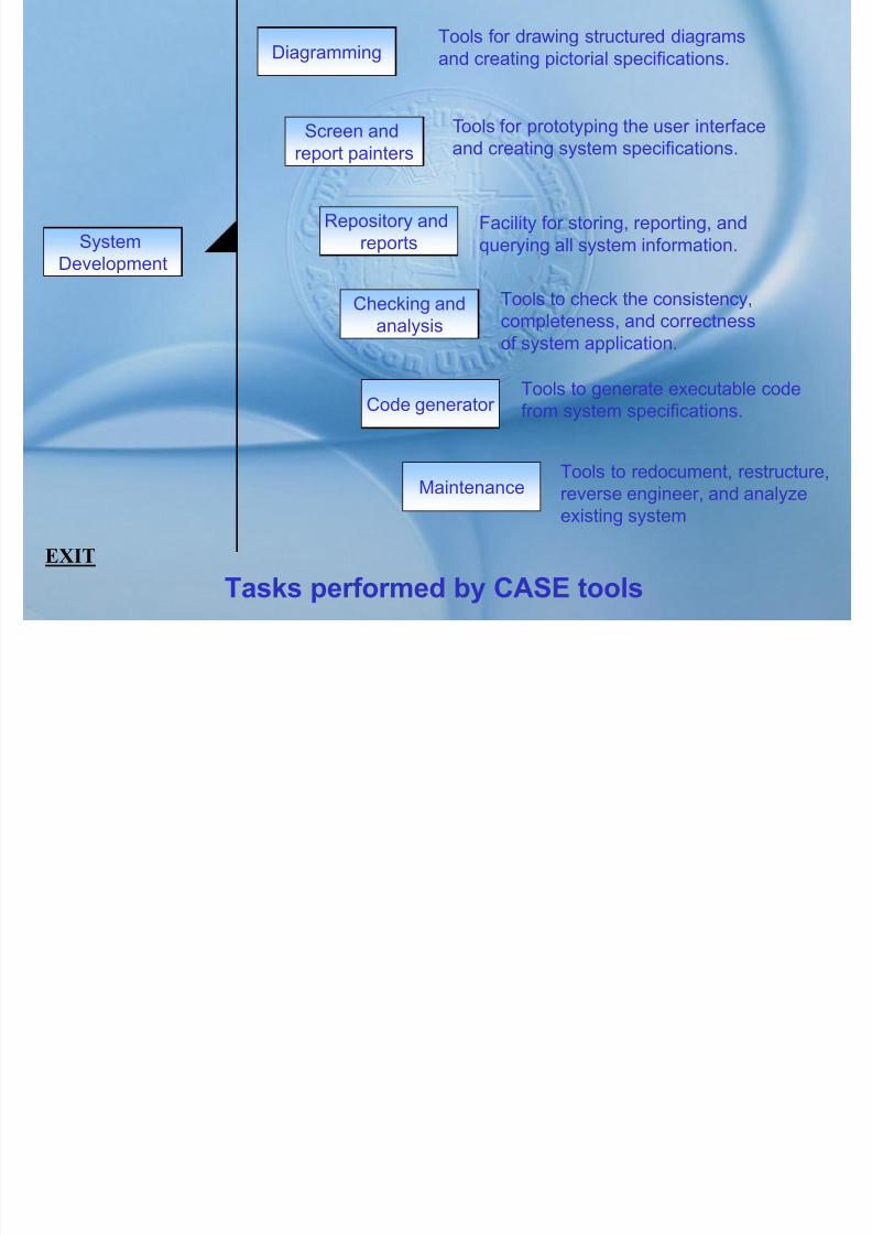
7/27/2019 MELJUN CORTES SYSTEM & ERD DBMS
http://slidepdf.com/reader/full/meljun-cortes-system-erd-dbms 337/396
Tasks performed by CASE tools
EXIT
Development
Checking andanalysis
Code generator
Maintenance
Tools to check the consistency,completeness, and correctness
of system application.
Tools to generate executable codefrom system specifications.
Tools to redocument, restructure,
reverse engineer, and analyzeexisting system
Interface
IRDS
subsystem
Performance
management
subsystem
Data integrity
management
subsystem
RepositoryLocal user

7/27/2019 MELJUN CORTES SYSTEM & ERD DBMS
http://slidepdf.com/reader/full/meljun-cortes-system-erd-dbms 338/396
Component of management system
EXIT
Sub-
system
DBMS
EngineBackup and
recovery
subsystem
Application
development
subsystem
Security
management
subsystem
Database
Operating
systemApplication
program
Remote
User

7/27/2019 MELJUN CORTES SYSTEM & ERD DBMS
http://slidepdf.com/reader/full/meljun-cortes-system-erd-dbms 339/396
Table with
Multivalued
attributes
First
Normal
Form
Thi d
Second
NormalForm
Remove multialuedattributes
Remove partial
dependencies
Remove transitive
dependencies

7/27/2019 MELJUN CORTES SYSTEM & ERD DBMS
http://slidepdf.com/reader/full/meljun-cortes-system-erd-dbms 340/396
Steps in Normalization
EXIT
Fourth
Normal
Form
Boyce-CoddNormail
Form
Third
Normal
Form
Fifth
Normal
Form
Remove remaining
anomalies resulting
from functional
dependencies
Remove multivalued
dependencies
Remove remaining
anomalies
Emp_ID Name Dept_Name Salary
EMPLOYEE1
(a) Functional Dependencies in EMPLOYEE1

7/27/2019 MELJUN CORTES SYSTEM & ERD DBMS
http://slidepdf.com/reader/full/meljun-cortes-system-erd-dbms 341/396
Representing functional dependencies
EXIT
(a) Functional Dependencies in EMPLOYEE1
Emp_ID Course_Title Name Dept_Name Salary Date_Completed
EMPLOYEE2
(b) Functional dependencies in EMPLOYEE2
EMPID NAME DEPT SALARY COURSE DATE
COMPLETED
100 Christopher Iresare Marketing 42,000 SPSS
Surveys
6/19/9x
10/7/9x
140 Jo B. Francisco Accounting 39,000 Tax Acc 12/8/9x
110 Cherlene Galang Info System 41,500 SPSS
C++
1/12/9x
4/22/9x

7/27/2019 MELJUN CORTES SYSTEM & ERD DBMS
http://slidepdf.com/reader/full/meljun-cortes-system-erd-dbms 342/396
(a) Table with repeating groups
EXIT
190 Geffrey Fabian Finance 38,000 Investments 5/7/9x
150 Julie Ann Atienza Marketing 38,500 SPSS
TQM
6/19/9x
8/12/9x
EMPID NAME DEPT SALARY COURSE DATE
COMPLETED
100
100
Christopher Iresare
Christopher Iresare
Marketing
Marketing
42,000
42,000
SPSS
Surveys
6/19/9x
10/7/9x
140 Jo B. Francisco Accounting 39,000 Tax Acc 12/8/9x
110
110
Cherlene Galang
Cherlene Galang
Info System
Info System
41,500
41,500
SPSS
C++
1/12/9x
4/22/9x

7/27/2019 MELJUN CORTES SYSTEM & ERD DBMS
http://slidepdf.com/reader/full/meljun-cortes-system-erd-dbms 343/396
(b) EMPLOYEE2 relation
EXIT
190 Geffrey Fabian Finance 38,000 Investments 5/7/9x
150
150
Julie Ann Atienza
Julie Ann Atienza
Marketing
Marketing
38,500
38,500
SPSS
TQM
6/19/9x
8/12/9x
Cust_NO Name Salesperson Region
8023 Geffrey Fabian South
9167 Jo Francisco West7924 Julie Atienza South
6837 Cherlene Galang East

7/27/2019 MELJUN CORTES SYSTEM & ERD DBMS
http://slidepdf.com/reader/full/meljun-cortes-system-erd-dbms 344/396
(a) Relation with transitive dependency
EXIT
g
8596 Tofy Iresare North
SALES
Cust_NO Name Salesperson Region
8023 Geffrey Fabian South
9167 Jo Francisco West7924 Julie Atienza South
6837 Cherlene Galang East

7/27/2019 MELJUN CORTES SYSTEM & ERD DBMS
http://slidepdf.com/reader/full/meljun-cortes-system-erd-dbms 345/396
(a) Relation with transitive dependency
EXIT
g
8596 Tofy Iresare North
SALES
Cust_NO Name Salesperson 8023 Geffrey Fabian9167 Jo Francisco
7924 Julie Atienza6837 Cherlene Galang8596 Tofy Iresare
Salesperson Region
Fabian SouthFrancisco West
Galang EastIresare north
sales1 SPERSON

7/27/2019 MELJUN CORTES SYSTEM & ERD DBMS
http://slidepdf.com/reader/full/meljun-cortes-system-erd-dbms 346/396
(b) Relation on 3NF
EXIT

7/27/2019 MELJUN CORTES SYSTEM & ERD DBMS
http://slidepdf.com/reader/full/meljun-cortes-system-erd-dbms 347/396
SHIPMENT
Snum Origin Destination Distance
409 Seattle Denver 1,537618 Chicago Dallas 1,058
723 Boston Atlanta 1,214
824 Denver Los Angeles 1 150

7/27/2019 MELJUN CORTES SYSTEM & ERD DBMS
http://slidepdf.com/reader/full/meljun-cortes-system-erd-dbms 348/396
Relation with transitive dependency
EXIT
824 Denver Los Angeles 1,150
629 Minneapolis St. Louis 587
SHIPTO
Snum Origin Destination
409 Seattle Denver 618 Chicago Dallas723 Boston Atlanta824 Denver Los Angeles629 Minneapolis St. Louis
DISTANCES
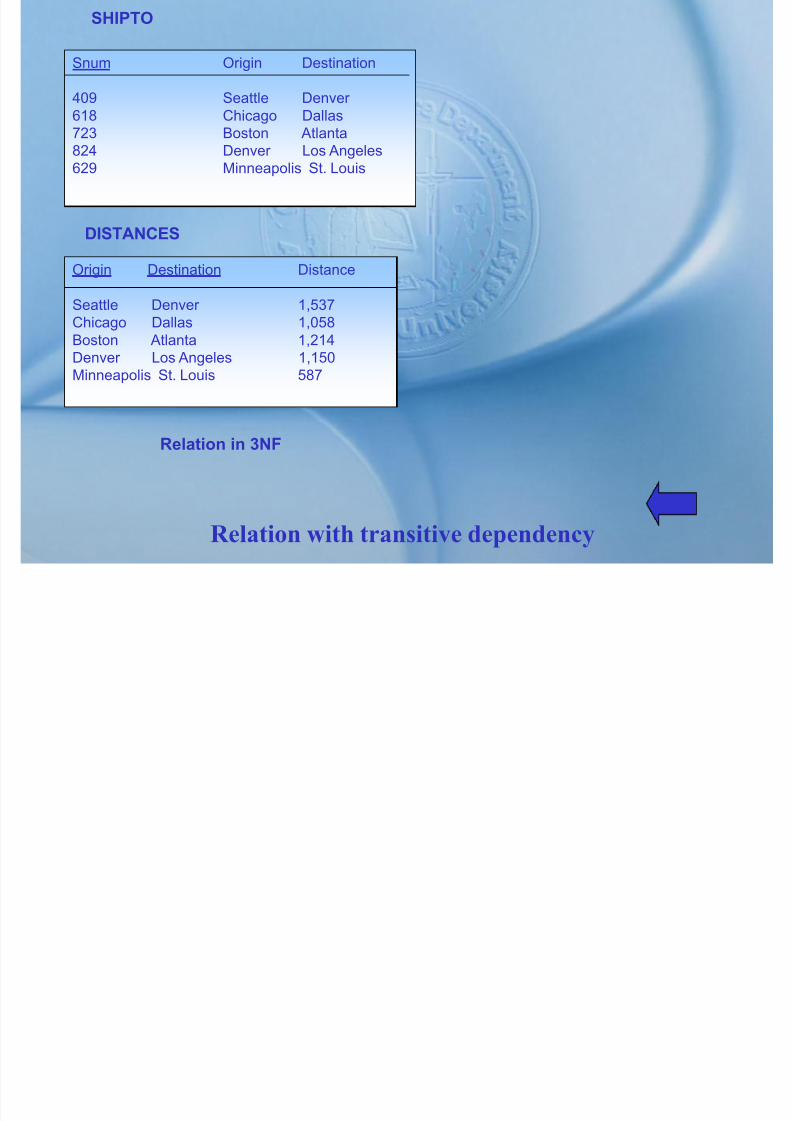
7/27/2019 MELJUN CORTES SYSTEM & ERD DBMS
http://slidepdf.com/reader/full/meljun-cortes-system-erd-dbms 349/396
Relation with transitive dependency
Origin Destination Distance
Seattle Denver 1,537
Chicago Dallas 1,058Boston Atlanta 1,214Denver Los Angeles 1,150Minneapolis St. Louis 587
Relation in 3NF
ADAMSON UNIVERSITY
GRADE REPORT
FALL SEMESTER 199x
NAME: Emily Williams ID: 268300458
CAMPUSADDRESS: 208 Brooks Hall
MAJOR: Information System

7/27/2019 MELJUN CORTES SYSTEM & ERD DBMS
http://slidepdf.com/reader/full/meljun-cortes-system-erd-dbms 350/396
Grade Report
EXIT
COURSE TITLE INSTRUCTOR INSTRUCTOR GRADE
ID NAME LOCATION
IS 350 DBMS Codd B 104 A
IS 465 SYSTEM Parsons B 317 B
StudentID
StudentName
Campus Address
Major CourseID
CourseTitle
Instructor
Name
Instructor Location
Grade
268300458 Williams 208brooks
IS IS 350 IS465
DBMSSYS.AN
AL
CoddParson
B 104 B317 AB
543291073 Baker 104Phillips
Acctg IS 350 Acctg201mktg 300
DBMSFundIntro
CoddMiller Bennett
B 104H 310B 212
CBA

7/27/2019 MELJUN CORTES SYSTEM & ERD DBMS
http://slidepdf.com/reader/full/meljun-cortes-system-erd-dbms 351/396
Table for Grade Report
mktg 300 Intro Bennett B 212 A
EXIT
StudentID
StudentName
Campus Address
Major CourseID
CourseTitle
Instructor Name
Instructor Location
Grade
268300458 Williams 208 brooks IS IS 350 IS465
DBMSSYS.ANAL
Codd Parson B 104B317
AB
543291073 Baker 104 Phillips Acctg IS 350 Acctg201mktg 300
DBMS FundIntro
Codd Miller Bennett
B 104H 310B 212
CB
A

7/27/2019 MELJUN CORTES SYSTEM & ERD DBMS
http://slidepdf.com/reader/full/meljun-cortes-system-erd-dbms 352/396
Grade Report Relation (1NF)
EXIT
GRADE
STUDENTI
D
MAJOR
CAMPUS
ADDRES
S
STUDENT NAME
KEY

7/27/2019 MELJUN CORTES SYSTEM & ERD DBMS
http://slidepdf.com/reader/full/meljun-cortes-system-erd-dbms 353/396
Functional Dependencies Grade Report
EXIT
COURSE
ID
INSTRUCTO
R NAME
COURSE
TITLE
INSTRUCTO
R LOCATION
STUDENT ID STUDENT
NAME
CAMPUS
ADDRESS
MAJOR
268300458
543231073
….
Williams
Baker
208 Brooks
104 Phillips
IS
Acctg
COURSE ID COURSE
TITLE
INSTRUCTOR
NAME
INSTRUCTOR
LOCATION
IS 350
IS 465
IS 350
Database mgt
System Analysis
Database mgt
Codd
Parson
Codd
B 104
B 317
B 104
(3NF)
(2NF)

7/27/2019 MELJUN CORTES SYSTEM & ERD DBMS
http://slidepdf.com/reader/full/meljun-cortes-system-erd-dbms 354/396
Relations obtained in Grade Report
EXIT
Acctg 201
Mktg
…..
Fund Acctg
Intro Mktg
Miller
Bennett
H310
B 212
STUDENT ID COURSE ID GRADE
268300458
268300458
543291073
543291073
543291073
…..
IS 350
IS 465
IS 350
Acctg 201
Mktg 300
A
B
C
B
A
(3NF)
COURSE ID COURSE TITLE INSTRUCTORNAME
IS 350IS465
Acctg 201Mktg 300….
Database MgtSystem Analysis
Fund AcctgIntro Mktg
CoddParson
Miller Bennett
(3NF)

7/27/2019 MELJUN CORTES SYSTEM & ERD DBMS
http://slidepdf.com/reader/full/meljun-cortes-system-erd-dbms 355/396
Relations obtained from COURSE INSTRUCTOR
EXIT
INSTRUCTOR NAME INSTRUCTOR LOCATION
CoddParsonMiller Bennett
B 104B 317H 310B 212
(3NF)
STUDENT ID MAJOR ADVISOR
123 Physics Einstein
123 Music Mozart
456 Biol Darwin
789 Physics Bohr
999 Physics Einstein

7/27/2019 MELJUN CORTES SYSTEM & ERD DBMS
http://slidepdf.com/reader/full/meljun-cortes-system-erd-dbms 356/396
ST MAJ ADV Relation
EXIT
ST MAJ ADV
ADVISOR MAJOR
Einstein PhysicsMozart Music
STUDENT ID ADVISOR
123 Einstein123 Mozart456 D i
ST ADV ADV MAJ

7/27/2019 MELJUN CORTES SYSTEM & ERD DBMS
http://slidepdf.com/reader/full/meljun-cortes-system-erd-dbms 357/396
Relations in BNCF
EXIT
Darwin BiolBohr Physics
456 Darwin789 Bohr 999 Einstein
OFFERING
COURSE INSTRUCTOR TEXTBOOK
Management white Drucker Green PetersBlack
Finance Gray Weston
OFFERING
COURSE INSTRUCTOR TEXTBOOK
Management White Drucker
Management Green Drucker Management Black Drucker Management White PetersManagement Green PetersManagement Black Peters

7/27/2019 MELJUN CORTES SYSTEM & ERD DBMS
http://slidepdf.com/reader/full/meljun-cortes-system-erd-dbms 358/396
Table with multi-valued dependencies
EXIT
(a) Table
Gilfordg
Finance Gray WestonFinance Gray Gilford
TEACHER TEXT
COURSE INSTRUCTOR
Management White
Management Green
Management Black
Fi G
COURSE TEXTBOOK
Management Drucker
Management Peters
Finance Weston
Fi Gilf d

7/27/2019 MELJUN CORTES SYSTEM & ERD DBMS
http://slidepdf.com/reader/full/meljun-cortes-system-erd-dbms 359/396
Relations in fourth normal form
EXIT
Finance Gray Finance Gilford
Planning
Analysis
Logical Database

7/27/2019 MELJUN CORTES SYSTEM & ERD DBMS
http://slidepdf.com/reader/full/meljun-cortes-system-erd-dbms 360/396
Role of physical database design
EXIT
design
Physical Databasedesign
Implementation
LOCATION
100
PATIENTTREATMENT PHYSICAL

7/27/2019 MELJUN CORTES SYSTEM & ERD DBMS
http://slidepdf.com/reader/full/meljun-cortes-system-erd-dbms 361/396
Logical Data model with volumes and ratios
EXIT
10004000 50
CHARGE
10,000
ITEM
500
TRANSACTION ANALYSIS FORM
TRANSACTION NO. _MVCH-4_________ DATE 4/12/9xTRANSACTION NAME: CREATE PATIENT BILL
TRANSACTION VOLUME:
AVERAGE:_2/HR.______________________ PEAK: 10/HR
TRANSACTION MAP:
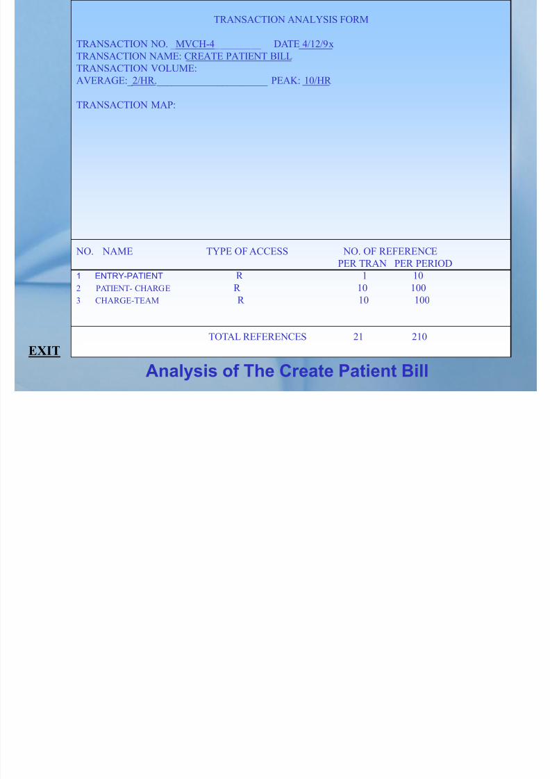
7/27/2019 MELJUN CORTES SYSTEM & ERD DBMS
http://slidepdf.com/reader/full/meljun-cortes-system-erd-dbms 362/396
Analysis of The Create Patient Bill
NO. NAME TYPE OF ACCESS NO. OF REFERENCE
PER TRAN PER PERIOD
1 ENTRY-PATIENT R 1 10
2 PATIENT- CHARGE R 10 100
3 CHARGE-TEAM R 10 100
TOTAL REFERENCES 21 210
EXIT
(a) Sequential
Start of File
CASTLESCOMBAT
CLASSICSQUEST TETRIS

7/27/2019 MELJUN CORTES SYSTEM & ERD DBMS
http://slidepdf.com/reader/full/meljun-cortes-system-erd-dbms 363/396
Comparison of File Organizations
EXIT
(b) Indexed
Key H V Z
A D H K M P Q W Z

7/27/2019 MELJUN CORTES SYSTEM & ERD DBMS
http://slidepdf.com/reader/full/meljun-cortes-system-erd-dbms 364/396
Comparison of File Organizations
EXIT
A-TRAIN CASTLES HUMANS QUEST
(c) Hashed
KeyHashing
AlgorithmRelative
Record No.

7/27/2019 MELJUN CORTES SYSTEM & ERD DBMS
http://slidepdf.com/reader/full/meljun-cortes-system-erd-dbms 365/396
Comparison of File Organizations
EXIT
CAPITALISTPIG
QUEST MANTIS A-TRAIN
Entity Relationship Primary key

7/27/2019 MELJUN CORTES SYSTEM & ERD DBMS
http://slidepdf.com/reader/full/meljun-cortes-system-erd-dbms 366/396
Basic Symbols
EXIT
Attribute Multi valued Attribute Gerund
NAME ADDRESS

7/27/2019 MELJUN CORTES SYSTEM & ERD DBMS
http://slidepdf.com/reader/full/meljun-cortes-system-erd-dbms 367/396
STUDENT NO.
NAME ADDRESS
EMPLOYEE
PHONE NO.
Entity type using E.R. notation
EXIT

7/27/2019 MELJUN CORTES SYSTEM & ERD DBMS
http://slidepdf.com/reader/full/meljun-cortes-system-erd-dbms 368/396
Attribute associated with the relationship
EXIT

7/27/2019 MELJUN CORTES SYSTEM & ERD DBMS
http://slidepdf.com/reader/full/meljun-cortes-system-erd-dbms 369/396
Relationship Cardinality
EXIT

7/27/2019 MELJUN CORTES SYSTEM & ERD DBMS
http://slidepdf.com/reader/full/meljun-cortes-system-erd-dbms 370/396
Binary
EXIT

7/27/2019 MELJUN CORTES SYSTEM & ERD DBMS
http://slidepdf.com/reader/full/meljun-cortes-system-erd-dbms 371/396
Gerund
EXIT

7/27/2019 MELJUN CORTES SYSTEM & ERD DBMS
http://slidepdf.com/reader/full/meljun-cortes-system-erd-dbms 372/396
possible combinations of minimum and maximum cardinalities
EXIT

7/27/2019 MELJUN CORTES SYSTEM & ERD DBMS
http://slidepdf.com/reader/full/meljun-cortes-system-erd-dbms 373/396
Identifying Relationship
EXIT
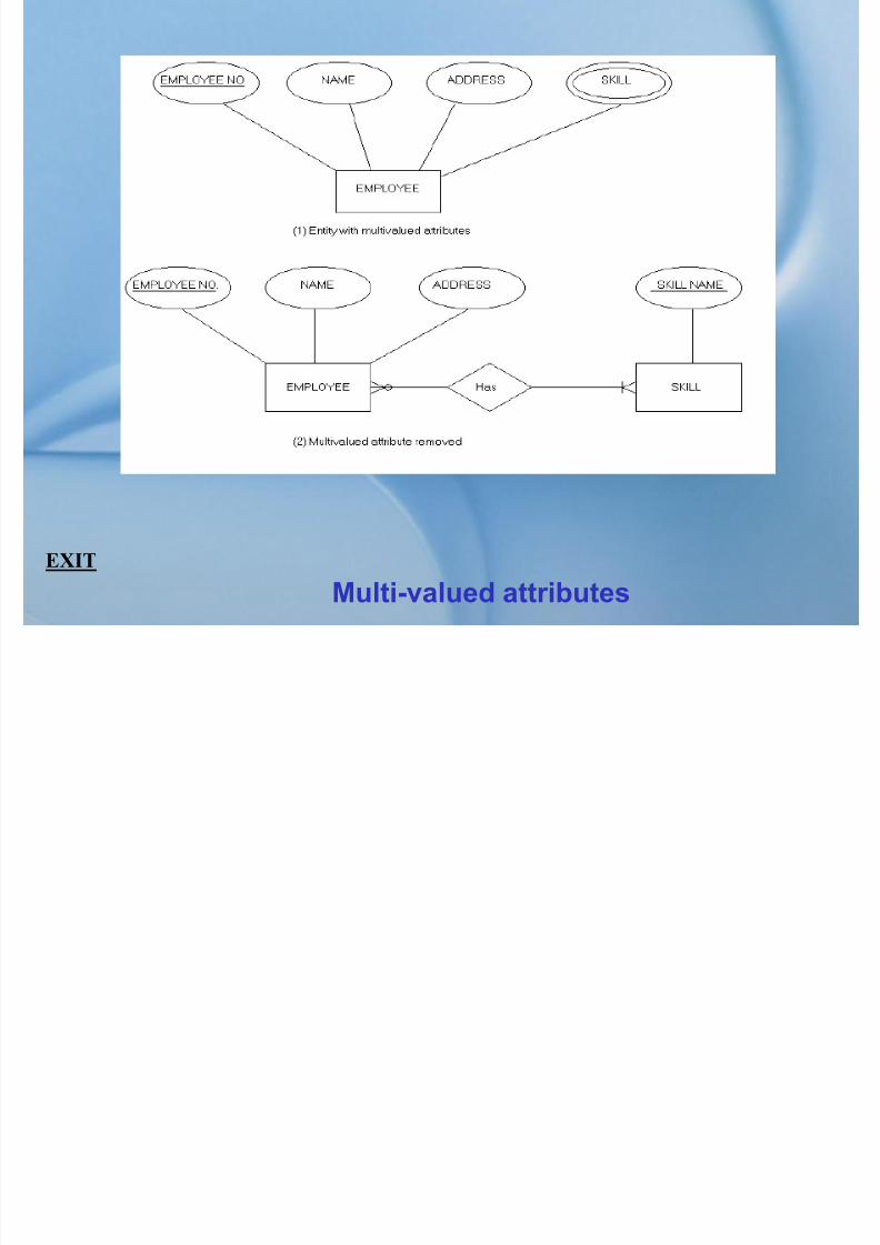
7/27/2019 MELJUN CORTES SYSTEM & ERD DBMS
http://slidepdf.com/reader/full/meljun-cortes-system-erd-dbms 374/396
Multi-valued attributes
EXIT

7/27/2019 MELJUN CORTES SYSTEM & ERD DBMS
http://slidepdf.com/reader/full/meljun-cortes-system-erd-dbms 375/396
Entity with repeating group
EXIT

7/27/2019 MELJUN CORTES SYSTEM & ERD DBMS
http://slidepdf.com/reader/full/meljun-cortes-system-erd-dbms 376/396
Repeating grouped removed
EXIT

7/27/2019 MELJUN CORTES SYSTEM & ERD DBMS
http://slidepdf.com/reader/full/meljun-cortes-system-erd-dbms 377/396
Employee Supertype with Subtype
EXIT
Business
scope
Business
model
Information
systems
model
1
2
3
Data Process Network
List of entitiesimportant tothe business
List of functionsthe business
performs
List of locationsin which the
business operates
Business entitiesand their
interrelationship
Function andprocess
decomposition
Communicationslinks between
business locations
Model of thebusiness dataand their interre-lationship
Flows betweenapplicationprocess
distributionnetwork

7/27/2019 MELJUN CORTES SYSTEM & ERD DBMS
http://slidepdf.com/reader/full/meljun-cortes-system-erd-dbms 378/396
Information systems architecture framework
EXIT
Technology
model
Technology
definition
Information
system
4
5
6
lationshipp
databasedesign
Processspecifications
Configurationdesign
Databaseschema andsubschemadefinition
Program codeand
control blocks
Configurationdefinition
Data andinformation
Applicationprograms
systemconfiguration
Model Name Role or
Perspective
Role Description
Business Scope
Business model
Information Systems
Owner
Architect
Designer
Provides a strategic overview including business
scope, mission, and direction.Develops business models that describes thebusiness scope, mission, and direction.
Develops information systems models that supportth b i

7/27/2019 MELJUN CORTES SYSTEM & ERD DBMS
http://slidepdf.com/reader/full/meljun-cortes-system-erd-dbms 379/396
Models and roles in the ISA framework
EXIT
yModel
Technology model
Technologydefinition
Information system
g
Builder
Contractor
User
the business.
Converts information systems models into a design
that conforms to be the features and constraints of the technology
Converts technology models into statements togenerate the actual information system.
Manages, uses, and operates the completedinformation system.
SystemDevelopment
Diagramming
Screen andreport painters
Repository andreports
C
Tools for drawing structured diagramsand creating pictorial specifications.
Tools for prototyping the user interfaceand creating system specifications.
Facility for storing, reporting, andquerying all system information.
Tools to check the consistency

7/27/2019 MELJUN CORTES SYSTEM & ERD DBMS
http://slidepdf.com/reader/full/meljun-cortes-system-erd-dbms 380/396
Tasks performed by CASE tools
EXIT
Checking andanalysis
Code generator
Maintenance
Tools to check the consistency,completeness, and correctnessof system application.
Tools to generate executable codefrom system specifications.
Tools to redocument, restructure,reverse engineer, and analyzeexisting system
1 Identify strategic planning factors
a. Goalsb. Critical success factors
c. Problem areas2 Identify corporate planning objects
a. Organizational unitsb. Locations
Planning

7/27/2019 MELJUN CORTES SYSTEM & ERD DBMS
http://slidepdf.com/reader/full/meljun-cortes-system-erd-dbms 381/396
Planning
EXIT
c. Business functionsd. Entity type
3 Develop enterprise model
a. Functional decompositionb .Entity-relationship diagramc. Planning matrixes
1 Develop conceptual data model
(detailed entity-relationship diagrams)2 Develop process models
(data flow diagrams)
Analysis

7/27/2019 MELJUN CORTES SYSTEM & ERD DBMS
http://slidepdf.com/reader/full/meljun-cortes-system-erd-dbms 382/396
Analysis
EXIT
1 Design databases
(normalized relations)2 Design processa. Action diagramsb. User interface: menus, screens, reports
Design

7/27/2019 MELJUN CORTES SYSTEM & ERD DBMS
http://slidepdf.com/reader/full/meljun-cortes-system-erd-dbms 383/396
Design
, , p
EXIT
1 Build database definitions
(tables, indexes, tablespace, etc.)2 Generate applications
(program code, control blocks, etc)
Implementation

7/27/2019 MELJUN CORTES SYSTEM & ERD DBMS
http://slidepdf.com/reader/full/meljun-cortes-system-erd-dbms 384/396
Implementation
EXIT
Business Planning
Market analysis
Sales forecasting
Product development
Finance and accounting
Capital budgeting
Account receivable
Human resources
Accounts payable
Functions Supportingfunctions

7/27/2019 MELJUN CORTES SYSTEM & ERD DBMS
http://slidepdf.com/reader/full/meljun-cortes-system-erd-dbms 385/396
Functional decomposition (Pine Valley Furniture)
EXIT
Marketing research
Order fulfillment
Materials management
Material requirement planning
Purchasing
Receiving
Distribution
Human resources
Recruiting
Production operations
Production scheduling
Fabrication
Assembly
Training
Finishing
Material requirements
planning
Determinegross
requirements
Determinenet
requirements
Function
Processes
(first level)

7/27/2019 MELJUN CORTES SYSTEM & ERD DBMS
http://slidepdf.com/reader/full/meljun-cortes-system-erd-dbms 386/396
Decomposing a function into processes
Determinefirm demand
Determineforecasted
demand
Calculategross
requirements
Processes
(second level)
EXIT
Planning
Analysis
Logical
database
design
Enterprise data model
Conceptual data model
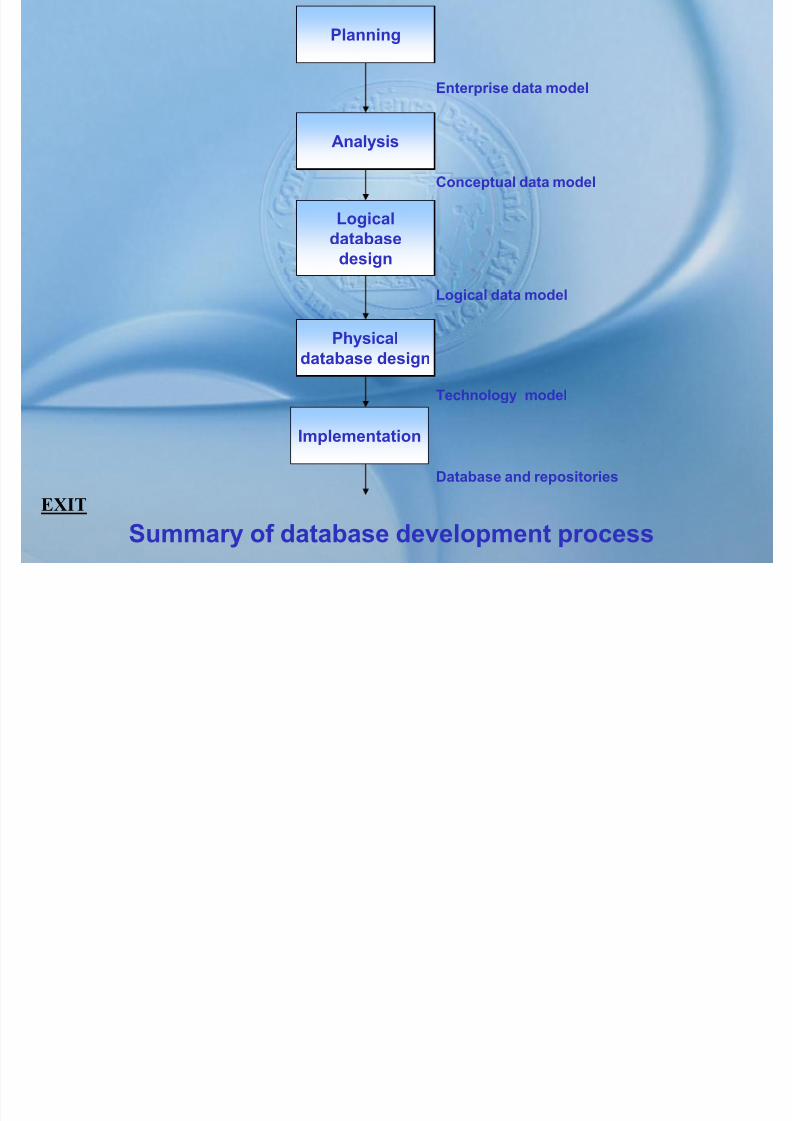
7/27/2019 MELJUN CORTES SYSTEM & ERD DBMS
http://slidepdf.com/reader/full/meljun-cortes-system-erd-dbms 387/396
Summary of database development process
EXIT
Physical
database design
Implementation
Logical data model
Technology model
Database and repositories
* *
* *
* *
*
* *

7/27/2019 MELJUN CORTES SYSTEM & ERD DBMS
http://slidepdf.com/reader/full/meljun-cortes-system-erd-dbms 388/396
Organizational-unit-versus-location
* *
This matrix shows the geographical location of organizationalunits(* = organizational unit at location).
EXIT
P S
P P
S PS S S

7/27/2019 MELJUN CORTES SYSTEM & ERD DBMS
http://slidepdf.com/reader/full/meljun-cortes-system-erd-dbms 389/396
Organizational-unit-versus-function
S P
This matrix shows which functions are performed by organizationalunits (P=primary responsibility; S=secondary responsibility)
EXIT
* * *
* *
* ** *

7/27/2019 MELJUN CORTES SYSTEM & ERD DBMS
http://slidepdf.com/reader/full/meljun-cortes-system-erd-dbms 390/396
Function-versus-process
*
This matrix shows which processes support business functions(* = process supports this function).
EXIT
E D D
E E
D D E
E
D
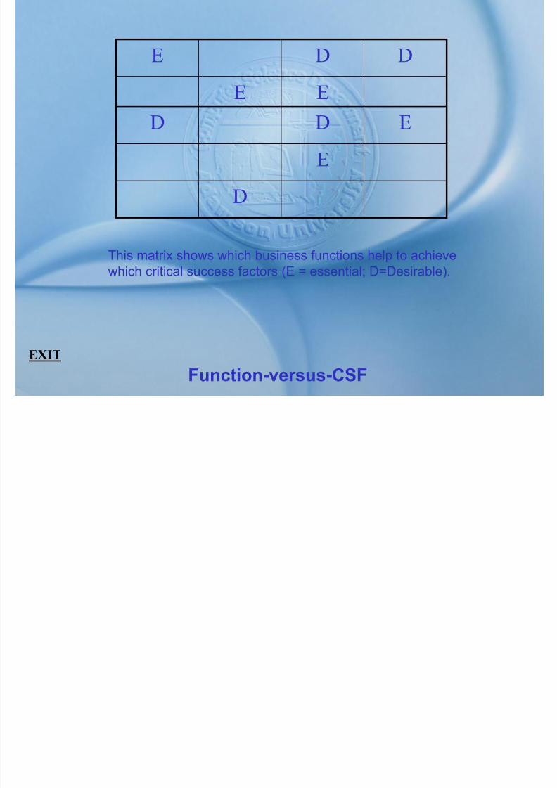
7/27/2019 MELJUN CORTES SYSTEM & ERD DBMS
http://slidepdf.com/reader/full/meljun-cortes-system-erd-dbms 391/396
Function-versus-CSF
D
This matrix shows which business functions help to achievewhich critical success factors (E = essential; D=Desirable).
EXIT
C U R U
U R U
R C R UR D U

7/27/2019 MELJUN CORTES SYSTEM & ERD DBMS
http://slidepdf.com/reader/full/meljun-cortes-system-erd-dbms 392/396
Process-versus-entity-type
R U C C
This matrix shows the use of entity types business processes(C=creates; R=reads; U=updates; D=deletes).
EXIT
P I
O P I
I PP O O I
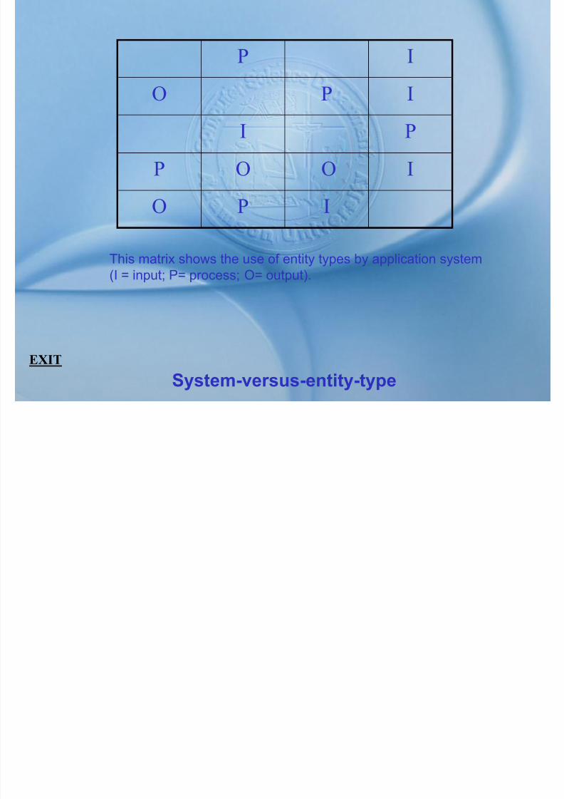
7/27/2019 MELJUN CORTES SYSTEM & ERD DBMS
http://slidepdf.com/reader/full/meljun-cortes-system-erd-dbms 393/396
System-versus-entity-type
EXIT
O P I
This matrix shows the use of entity types by application system(I = input; P= process; O= output).
LOCATION ACCOM
ROOM
MayB A i d
IsBilled
for AttendsPROCEDURE CHARGE
PHYSICIAN ITEM

7/27/2019 MELJUN CORTES SYSTEM & ERD DBMS
http://slidepdf.com/reader/full/meljun-cortes-system-erd-dbms 394/396
Conceptual data model (mountain view hospital)
EXIT
Be Assignedto
PATIENT
PATIENT_NO
LOCATION
Other patientattributes
PATIENTNAME
PATIENT ADDRESS
EXTENSION
PHYSICIAN ITEM
DESCRIPTION
ITEMCODE
PHYSICIANID
PHYSICIANCODDE
(a) Result of equi-join
PATIENT_NO DATE_DISCH.
1234 05/20/83
0675 06/23/832345 02/28/83
B_PATIENT_NO B_CHARGE
2345 23.00
2345 65.001234 80.501234 125.00
PATIENT BILLED
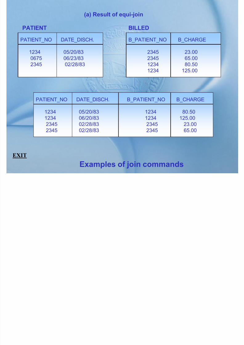
7/27/2019 MELJUN CORTES SYSTEM & ERD DBMS
http://slidepdf.com/reader/full/meljun-cortes-system-erd-dbms 395/396
Examples of join commands
EXIT
PATIENT_NO DATE_DISCH.
1234 05/20/831234 06/20/832345 02/28/832345 02/28/83
B_PATIENT_NO B_CHARGE
1234 80.501234 125.002345 23.002345 65.00
(b) Result of Natural-join
B_PATIENT_NO DATE_DISCH. B_CHARGE
1234 05/20/83 23.001234 05/20/83 65.002345 05/28/83 80.502345 05/28/83 25.00
BILL_DATA

7/27/2019 MELJUN CORTES SYSTEM & ERD DBMS
http://slidepdf.com/reader/full/meljun-cortes-system-erd-dbms 396/396
Examples of join commands
EXIT
(c) Result of outer-join
B_PATIENT_NO DATE_DISCH. B_CHARGE
1234 05/20/83 23.001234 05/20/83 65.002345 05/28/83 80.502345 05/28/83 25.000675 06/23/83 ?
BILL_DATA