melsec f1 series - inverter & plc - mitsubishi plc plc,f-f… · · 2013-08-101-3 program and...
TRANSCRIPT

CONTENTS
1 . Introduction ...................................................................................................................... 1 1-1 Location and function of programmable controller ................................................ 1 1-2 Internal configuration of programmable controller ............................................... 2
1-4 Differences between relay panel and programmable controller ........................... 6 1-3 Program and instruction concept ............................................................................ 4
2 . Elements and Element Nos ................................................................................................ 2-1 Input relay (X) ........................................................................................................... 2-2 Output relay (Y) ......................................................................................................... 2-3 Auxiliary relay (M) ....................................................................................................
2-5 Special auxiliary relay (M) .......................................................................................... 2-6 Timer (T) .................................................................................................................... 2-7 Counter (C) ................................................................................................................... 2-8 State (S) ........................................................................................................................
2-4 Shift register (M) .......................................................................................................
10 10 11 12 14 16 18 20 24
3 . Basic sequence instructions ............................................................................................ 25 - LD/LDI/OUT, AND/ANI, ORIORI, ORB, ANB ............................................................ 25-29 - S/R, PLS, RST, SFT ................................................................................................... 31-34 - MC/MCR, NOP .......................................................................................................... 35-37 - CJP/EJP, END ........................................................................................................... 38-42
4 . Step ladder instruction .................................................................................................... 43 . . 4-1 Overall configuration of circuit ................................................................................ 43
4-2 Automatic sequence program ................................................................................. 48 4-3 General sequence of mode selection, etc ............................................................... 55 4-4 Manual operation sequence .................................................................................... 59 4-5 Handling of multiple flows ....................................................................................... 62
5-1 Inputloutput high-speed processing instruction .................................................... 71 5-2 Instructions concerning reset ................................................................................ 76 5-3 Data transfer instruction ........................................................................................... 79 5-4 Compare instruction for current counter value ...................................................... 83 5-5 Auto re-load (AUTO RELOAD) of pair counter ....................................................... 88 5-6 Direct output instruction for high-speed counter ................................................... 92
5 . Functional Instructions ...................................................................................
6 . Summary - Table 6-1 Sequence instruction and execution time ................................................ 98 - Table 6-2 Functional instructions and execution times ............................................ 99 - Table 6-3 List of special auxiliary relays ...................................................................... 100 - Table 6-4 List of element Nos ..................................................................................... 101
I . . . . . . . . . . . . . . . . . . . . . . : .:i. :... ;
I

~ ~~ ~
1 Location and function of programmable controller
Unit to indicate when/ how lo operate equipment
[a Pushbutton Wl] I Switch Digital I
switch I I f Operation
switch Indication unit
I Pilot lamp Digital indicator
Unit to inform equipment condition
Operation panel
Unit to detect equipment condition
f 3 Detection unit
Power source
7 I .. . . , .
Programmable Input controller
Limit switch
O b Solenoid Elcctrornagnetic valve Clutch
c Drive unit Control unit
\
Unit to determine equipment condition to provide instruction equipment
Control panel Machine
Fig. 1-1 Location of programmable controller
The programmable controller (PC in short) is operated by the instruction input from the pushbutton switch, selector switch, digital switch, etc. provided on the operation panel, or sensor input from the l imit switch, proximity switch, photo-electric switch, etc. used to detect the operation condition of the equipment, and serves to control the driving loads such as solenoid valve, motor, electromagnetic clutch, etc. and indication loads such as pilot lamp, digital indicator, etc. The transmission of output signal against these input signals is determined by the contents of program to be provided to the programmable controller. The light loads such as small type solenoid valve, pilot valve, etc. can be directly driven by the programmable controller, however, the heavy loads such as 3-phase motor, large- capacity solenoid valve, etc. need to be driven through the contactor or the intermediate relay. Such contactor, intermediate relay, power breaker, etc. are installed in the control panel together with the programmable controller. The programmable controller will play the important roles as a small type, high-reliability and flexible brain when designing the automated product machining, assembling, transfer, inspection, packing, etc.
1
1-2
Input relay is Internal sequence actuated by is actuated by extermal signal. input relay contact
Internal configuration of programmable controller -- Output relay External load operation is sent is actuated. to external unit.
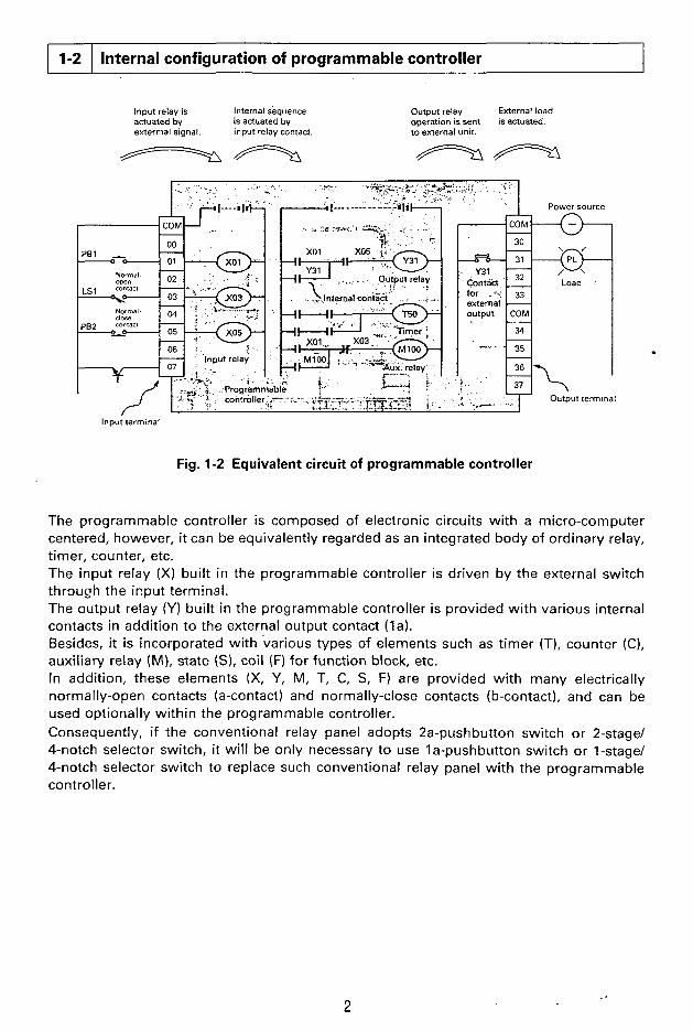
The programmable controller is composed of electronic circuits with a micro-computer centered, however, it can be equivalently regarded as an integrated body of ordinary relay, timer, counter, etc. The input relay (X) built in the programmable controller is driven by the external switch through the input terminal. The output relay (Y) built in the programmable controller is provided with various internal contacts in addition to the external output contact ( la). Besides, it is incorporated with various types of elements such as timer (TI, counter (C), auxiliary relay (M), state ( S ) , coil (F) for function block, etc. In addition, these elements (X, Y, M, T, C, S, F) are provided with many electrically normally-open contacts (a-contact) and normally-close contacts (b-contact), and can be used optionally within the programmable controller. Consequently, if the conventional relay panel adopts 2a-pushbutton switch or 2-stage/ 4-notch selector switch, it will be only necessary to use la-pushbutton switch or I-stage/ 4-notch selector switch to replace such conventional relay panel with the programmable controller.
Fig. 1-2 Equivalent circuit of programmable controller
f
2

NOTE
Since the input relay (X05) in Fig. 1-2 is driven through the pushbutton switch (b-contact), the output relay (Y31) can be latched by actuating the input relay (X01). When the pushbutton switch (PB2) is depressed to turn off the input relay (X051, the output relay (Y31) is turned off at the same time. (Be careful that the contact X05 is a normally-open contact in the program). In the case of auxiliary relay (MIOO), on the other hand, the contact of input relay (X03) is used as a normally-close contact, therefore, the latching condition of auxiliary relay (M100) is reset when the limit switch (LSI) is actuated, causing the input relay (X03) to actuate.
.. . ~ : . < , ~ . . . .:..... . . \ ...., ..;. !i;
1-3
Simplified programming of complicated internal wiring by the use of programming panel -
Program and instruction concept
Use a cutting pliers or screwdriver for input/ output wiring as u
T
conventional
COM * = Y30
Y31
Y32
Y33
COM
Y34
Y35
Y36
Y37
- - - - - -
. - - -
pi4q MlOO
Programmable controller
Programmable contro!ler
( a ) Inputloutput wiring diagram (b! Sequence circuit diagram
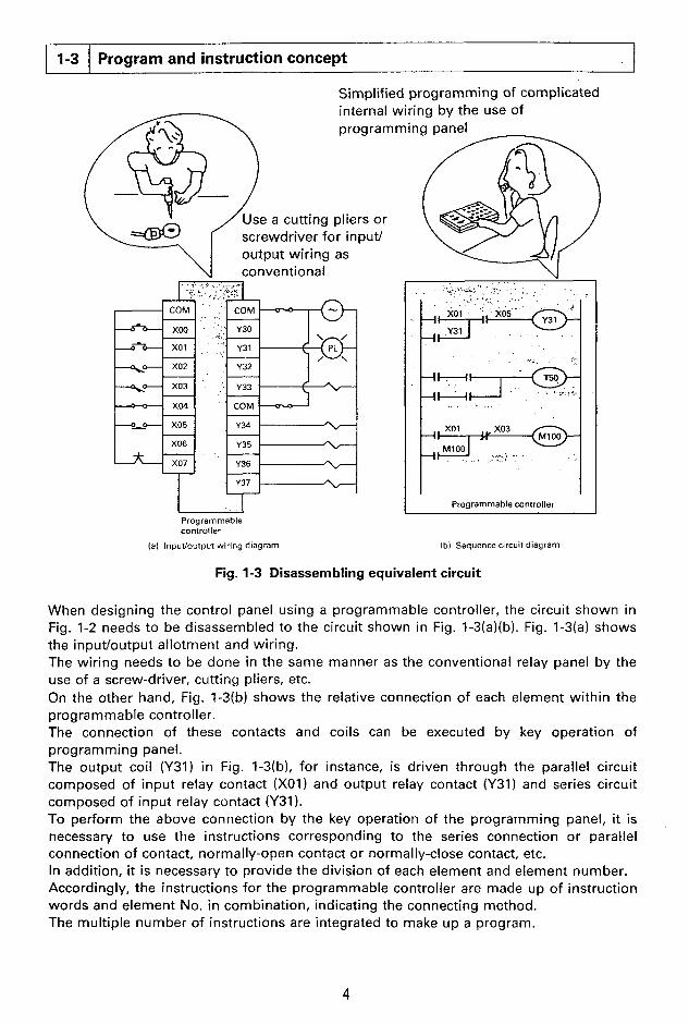
Fig. 1-3 Disassembling equivalent circuit
When designing the control panel using a programmable controller, the circuit shown in Fig. 1-2 needs to be disassembled to the circuit shown in Fig. 1-3(a)(b). Fig. 1-3(a) shows the i np utlo utput a I lotm ent and wiring . The wiring needs to be done in the same manner as the conventional relay panel by the use of a screw-driver, cutting pliers, etc. On the other hand, Fig. 1-3(b) shows the relative connection of each element within the program m a ble co ntro I ler . The connection of these contacts and coils can be executed by key operation of progra mming panel. The output coil (Y31) in Fig. 1-3(b), for instance, is driven through the parallel circuit composed of input relay contact (XOI) and output relay contact (Y31) and series circuit composed of input relay contact (Y31). To perform the above connection by the key operation of the programming panel, it is necessary to use the instructions corresponding to the series connection or parallel connection of contact, normally-open contact or normally-close contact, etc. In addition, it is necessary to provide the division of each element and element number. Accordingly, the instructions for the programmable controller are made up of instruction words and element No. in combination, indicating the connecting method. The multiple number of instructions are integrated to make up a program.
4

NOTE
[ I ] Program capacity and step No.
A large number of instructions making up a
Step Inst- Element program are assigned with sequential No., No. ruction No. each of which is called "Step No.".
0 LD xo1 In the MELSEC F, series, it is possible to 1 OR Y31 assign step Nos. in the range from "0" to 2 AND X05 "999", which allows the programming a total
3 OUT Y31 of 1,000 instructions. It is referred to as a "Program capacity":
999 END
[2] Program memory
As explained previously, each element used in the programmable controller is provided with a number of contacts, however, the actual number of contact to be used will be restricted by the program capacity.
A memory used to store such large number of instructions is called "Program memory". The program memory is optionally available in the EPROM memory, EEPROM memory, etc. in addition to the RAM memory incorporated in the programmable controller.
RAM memory (built in programmable controller) The memory allows the instantaneous writingheading, however, it is designed to hold the memory contents by the battery back-up (built in programmable controller), as the contents of memory may be lost in the event of power failure. The memory is applicable to the test operation stage in which the program may be frequently modified. EPROM memory (type F-ROM-1 ROM cassette, option) The memory is used exclusively for reading, and requires the speciai devices (ROM writer, eraser) for writing, correction and erasing. Since the memory of this type is most resistible against the noise and the program once stored will not be lost, it is suitable to maintenance-free application. EEPROM memory (type F-EEPROM-1 ROM cassette, option) The program in the memory will not be lost even in the event of power failure in the same manner as the EPROM memory. The memory of this type will not require any special device for writing and erasing, which can be executed by the use of programming panel.
121 Cover With the type F-ROM-1 or type F- EEPROM-I ROM cassette mounted to the programmable controller, the programmable Controller will operate in accordance with the
@D ROM cassette (with program written)
~- ------7
- - - Q Programmable
controllet
contents of program stored in the ROM cassette.
The operation contents of the programmable controller can be changed with ease simply by replacing the ROM cassette.
l - 5
........
1-4
. . . . . . . . . . . . . . . . . . . . . . . .._, . . . . . . . . . . . . . , ~ . ...... . . . .
Differences between relay panel and programmable controller
(1) Input/output processing
x1 x2
x3
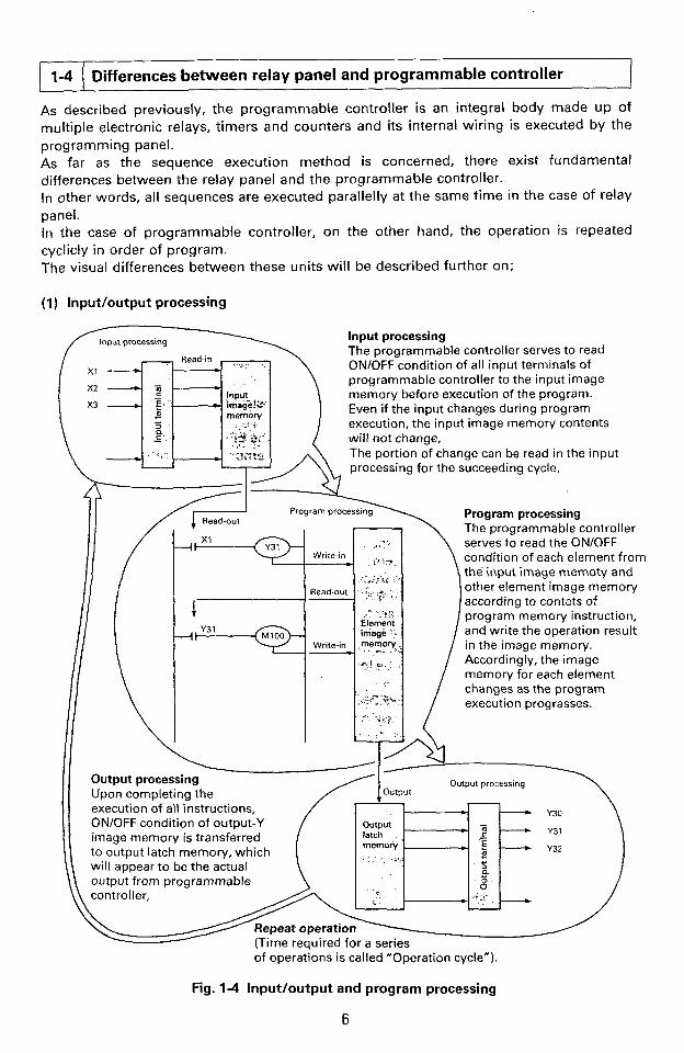
Input processing The programmable controller serves to read ONlOFF condition of all input terminals of programmable controller to the input image memory before execution of the program. Even if the input changes during program execution, the input image memory contents will not change, The portion of change can be read in the input processing for the succeeding cycle.
Program processing The-progiamrna ble-controller serves to read the ONlOFF condition of each element from the input image memoty and other element image memory according to contets of program memory instruction, and write the operation result in the image memory. Accordingly, the image memory for each element changes as the program i execution prograsses.
Output processing
I Output processing Upon completing the - execution of all instructions, - Y30 ON/OFF condition of output-Y
+ - Y31 L
- -
memory + E - - - - image memory is transferred to output latch memory, which - I I c
will appear to be the actual a
output from programmable 0'
of operations is called "Operation cycle").
Fig. 1-4 Input/output and program processing
6

(2) Input/output response lagging The programmable controller has the response lagging due to influence of operation cycle in addition to the electrical lagging (approx. 10ms) due to input filter and mechanical response lagging (approx. 10ms) due to output relay. 4s an example, the consideration will be made on the sequence as shown in Fig. 1-5 in which the input terminal X I is changed from OFF to ON right after the input processing has been completed.
Input processing - X1 terminal input - OFF
- X1 image memory +
Input X1 after input processing= OFF+ON
t i'-t 7 rly3l m - - t Ymimagememory -+
O i % - f i " l *
r-@-----f Y32 image memory --c
Y30 terminal output - Y31 terminal output
Y32 terminal output - OFF
I
Fig. 1-5 Input/output response lagging
1 st cycle 2nd cycle 3rd cycle Since X I in input image memory is OFF, all the output relays Y30, Y31 input processing, the also turned on. and Y32 are turned off.
Since X I in image memory is turned on by
image memory is turned on when Y31 is executed. The image memory of Y32 is turned on similarly.
Since the image memory of Y31 is turned on, Y30 is
As described above, a maximum of two-cycle response lagging will occur in Y31 and "32 after the input has been turned on.
i
NOTE
lnprovement of input/output response lagging Since there are the function instructions which allows the input processing/ output processing while the program is being executed, the response lagging as above can be reduced by the use of such instruction. In addition, the F, series is prepared with other function block which makes it possible to reduce the response lagging of input filter by the program.
7

I
(3) Double output operation
-I
Y33 Thesecond G!+
-4 ~~
I
Fig. 1-6 Double output
Considered in the following is a case in which the equivalent coil Y33 is used at multiple locations as shown in Fig. 1-6. As an example, it is supposed that X I is turned on and X2 is turned off during input processing. Since XI is turned on, the memory image of the 1st Y33 is turned on. Consequently, Y34 in the succeeding circuit will be also turned on. Since X2 to the 2nd Y33 is OFF, however, the image memory of Y33 will be re-written to OFF. As a result, the actual output when the output processing is executed will result in that Y33 is turned off and Y34 is turned on. Bear in mind that the execution of double output as stated above will cause the operation executed later to be a preferential operation. Besides, the double output will come in different way when the jump-instruction or step-ladder instruction is used, which will be described further on.
r 8

(4) Un-programmable circuit
a a to be corrected
(a1 Bridging circuit Ibl Reversing circuit
a
(c) Branch output circuit
Fig. 1-7 Un-programmable circuits and countermeasures
Since the circuit as shown at the upper stage of Fig. 1-7 cannot be programmed directly, it is necessary to program by changing the circuit to that shown at the lower stage. In the upper figure in Fig. 1-7(a), the problem is that the current flows across the contact-5. In the upper figure in Fig. 1-7(b), on the other hand, the problem is that the contact-3 is used after the coil-4. In addition, it is necessary to program the coil-5 which is not accompanied by any contact, before the coil-4. The circuit as showq in Fig. 1-7(c) is pwgrammed by the use of master control instruction to be given further on.
9
! . . :: . . .... C..? :i:q: .::.: ,;;.

.. .. ..
2-1
..: .. ., .,. ,, : :. " :. , . ,. .:.. .. , ...... . .
Input relay (X)
The instructions used for programmable controller can be divided into those which function by themselves and those which will function with "Instruction + element No." in combination. This section at first describes the kinds of elements and their Nos.
External input contact Normal-open contact
.. * ,@,. : A
Fig. 2-1 Input relay circuit
"Input" is a window through which the signal is received by the programmable controller from the external switch. The input relay (XI connected to the input terminal of the programmable controller is an electronics relay which is insulated optically, and is provided with a number of normally-open contacts (a-contact) and normally-close contacts (b-contact). These contacts may be used optionally within the programmable controller. It is not possible to drive the input relay by the contact incorporated in the programmable controller.
Input relay No. The input relay (X) is assigned with No. in octal figure as shown below, depending upon the basic unit or extension unit. (For details, refer to page 163). A part or al l of these input relays may be used, depending upon the type of programmable controller used.
Basic unit Extension unit
X400 - X407 X410 - X413 X414 - X417 X420 - X427 X500 - X507 X5 10 - X513 X514 - X517 X520 - X527
NOTE
Response time lagging of input relay The input relay has the following response lagging due to influence by C-R filter. Since eight points of input X400 - X407 can be changed filter constant by the program, both ON and OFF response time lagging can be zero to 60ms. (See functional instruction F670 K l O l ) . The standard response lagging in input X400 - X407 is approx. 10ms both for OFF + ON and ON -+ OFF.
10
1
e
4
2-2
1:- YOXI (internal norinal-open contact) . ' . +- YO30 (iritcrnal norincll-closc contac!)
Output relay (Y)
External power source
NOTE: XOOO, XOOI, Y030, etc. may be written as XO, X I and Y30.
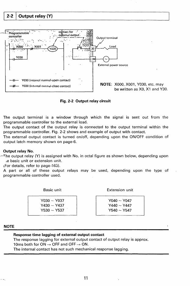
Fig. 2-2 Output relay circuit
The output terminal is a window through which the signal is sent out from the programmable controller to the external load. The output contact of the output relay is connected to the output terminal within the programmable controller. Fig. 2-2 shows and example of output with contact. The external output contact is turned on/off, depending upon the ON/OFF condition of output latch memory shown on page-6.
I
Output relay No. -The output relay (Y) is assigned with No. in octal figure as shown below, depending upon
re basic unit or extension unit. (For details, refer to page-163). A part or all of these output relays may be used, depending upon programmable controller used.
Basic unit Extension unit
Y430 - Y437 Y530 - Y537
YO40 - YO47 Y440 - Y447 Y540 - Y547
I 1 1
NOTE
the type of .
!
Response time lagging of external output contact The response lagging for external output contact of output relay is approx. 10ms both for ON -+ OFF and OFF -+ ON. The internal contact has not such mechanical response lagging.

. -. .. .. ,
2-3 Auxiliary relay (M)
I
Fig. 2-3 Auxiliary relay circuit
128 points auxiliary relay are provided for the general use, each of which is assigned with octal number ranging from MI00 to MI77 and from M200 to M277.
(2) M300 - M377 (64 points: octal No.) for retentive use (Battery back-up) Should the power failure occur while operating the programmable controller, the output relays and auxiliary relays will be all turned off. All these condition except those of which input conditions are turned on will also be turned off when the opera th i is re-started. However, some control objects may be necessary to re-produce when the operation is re-started, by storing the pre-power failure conditions. These auxiliaw relays are used for such purpose, and the memory is held in the event of power failure by the back-up memory incorporated in the programmable controller.
t
1 b4 Programmable I I I controller I
, I I . ._- . - _ . - * _ . -
Fig. 2-4 Holding circuit in the event of power failure (self-holding type)
c 12

Fig. 2-4 shows an example in which the operation of M300 is held in the event of power failure. If M300 is actuated with X400 turned on in this circuit, M300 self-holds the operation even if X400 is opened. - Accordingly, M300 continues the operation when the operation is re-started even if X400 is opened due to power failure. If the normally-close contact X401 is opened, on the contrary, M300 will become inoperative.
Fig. 2-5 Holding circuit in the event of power failure (set/reset type)
When using the sedreset instruction to be described further on, the circuit will be as shown in Fig. 2-5.
13
!

2-4
Shift register No. (1) MI00 - MI17 (7) M240 - M257 (2) MI20 -- MI37 (8) M260 - M277 (3) M140 - MI57 (9) M300 - M317 )
~ ~
Shift register (M)
(4) M160 - MI77 (5) M200 - M217
M320 - M337 Battery back-up (1 1) M340 - M357
(6) M220 - M237 (12) M360 - M377 I
Fig. 2-6 Shift register (Example of M300) c Operation of shift register (1) Handling of data input
The ONlOFF condition of leading auxiliary relay M300 is established by the ON/OFF condition of data input X400. Accordingly, the operation is the same as that shown below.
(2) Handling of reset input When the reset input X402 is turned on, M301 - M317 are all turned off. When they need to be operated as shift registers, therefore, it is necessary to turn off the reset input.
When the shift input X401 is turned from OFF to ON, ON(I)/OFF(O) condition of each auxiliary relay will be changed as follows;
(31 Handling of shift input
14

X400 - + Overflow
It is also possible to receive the over-flow contents by combining the siftregister with a second one and cascade the two. (Refer to page-34).
(4) Sedreset of intermediate relay For the auxiliary relays M200 - M377, it will be possible to turn onloff any auxiliary relay in the shift register. The setheset instruction is used for the purpose as shown below; Bear in mind that the use of general coil drive instruction (OUT instruction) may result in mal-operation of shift register.
M304 is turned on when X500 is turned on.
M312 is turned off when X501 is turned on.
Reference circuit example
ON
If the shift input X401 is turned on/off repeatedly in the above figure, ither one of the auxiliary relays M200 - M217 is operated in order of M200 + M201 + M202 ... In the initial operation, M201 - M217 are all turned off (normally-close contacts are a l l turned on), and only M200 is operated through X400 (ON). When the shift input X401 is turned from OFF to ON in this case, M201 is turned on, and the normally-close contact is opened, causing M200 to be turned off.
15 !

..... -.
2-5 ~~
Special auxiliary relay (M)
Initialize,
100ms clock
10ms clock
........................... M74
M75 ........................... ...........................
Battery
1 inhibit
High-speed
Programmable J'Prdg%rn&able controller RUN 1 controller STOP
M70 is turned on/off automati- cally, depending upon RUN/ STOP condition of the prog- -
M70 = OFF rammable controller. M70. y ON
The contact of M70 is used to drive the functional instruction, etc.
M71 is turned on only for one execution cycle right after M70 has been turned on.
initialize the counter, shift regis- ter, state, etc.
M70 . :.:,. M70 .
n n The contact of ~ 7 1 is used to + /-- 1 execution cycle
50ms* 50ms
Normally turned on in F, series.
M72 is turned on/off at an inter- val of looms, and M73 at an interval of 10ms.
Counting this contact operation by the counter provide with the timer of 0.1 - 99.9sec. and 0.01 - 9.99sec.
" When the battery voltage is dropped, M76 is turned on while power to the programmable controller is supplied. It is possible to indicate the battery voltage drop condition with the externa! unit by driving the output relay (Y) by the use of this contact to turn on the lamp. (RAM program has been held for approx. one month after M76 has been operated).
When M77 coil is operated by program, al l output relays (Y) are automatically turned off. In this case, other relays, timers and counters are kept operated.
p 7 q Image memory of all
output is reset when
executed. OUT instruction is
The counters C660 and C661 are prepared in pairs to make up a 6-digit counter (pair counter). The count input t o the counter is used selectively as follows, depending upon ON/OFF condition of M470.
- In case M470 is ON
X400 is treated as count input and M401 as reset input and input filter for X400 and X401 is turned to be approx. 2 0 0 ~ s automatically, so that the high-speed counting of 2kHz can be executed. (1.5kHz for functional instruction F670 K119 is used) 0
16

U P/DOW N SELECTION
Start-up signal
u Error flag
Zero flag M573 Borrow flag
In case M470 is OFF
The optional contact in the programmable controller can be treated as count input or reset input. In this case, however, the operation limit will be normally several dozens of Hertz, as the counting speed depends on the execution cycle of the programmable controller.
Designates the counting direction of pair counters C660 and C661.
M472 = ON ..... Up count
M472 = OFF ..._. Down count
Available in case the pair counters C660 and C661 are used as high-speed counters (M470 = ON).
- M472 = ON ..... Counting executed
- M472 = OFF ..... Counting not executed
M473 is turned on when the current value of the counter is changed from 999999 to 0 (up-count) or from 0 to 999999 (down-count). The functional instruction F670 K110 is used for resetting. In case the pair counters are used as down counters, it is possible to make up a 9-digit counter by counting the operation of M473 by the other counters.
This flag is turned on when the wrong object element No. is set for condition setting coil of the functional instruction. It is turned off when the setting is correct. In case a number of function instructions are used, which may influence the operation of this flag, M570 is turned on or off each time the functional instruction is executed.
M571 - M573 are operated when the functional compare instruc- tion is executed for the current counter value, depending upon " G reat ' I , " S m a I I " or "Coincidence " .
Example In case compare setting is "100"
Current counter value (0 - 99) + M573 = ON
Current counter value ( loo)+ M572 = ON
Current counter value (101 - 999) + M571 = ON
In addition, the carry flag M571 is also used for functional instructions F670 K113, K115 and serves to detect the interrupt input information.
1
17
. . .. ._
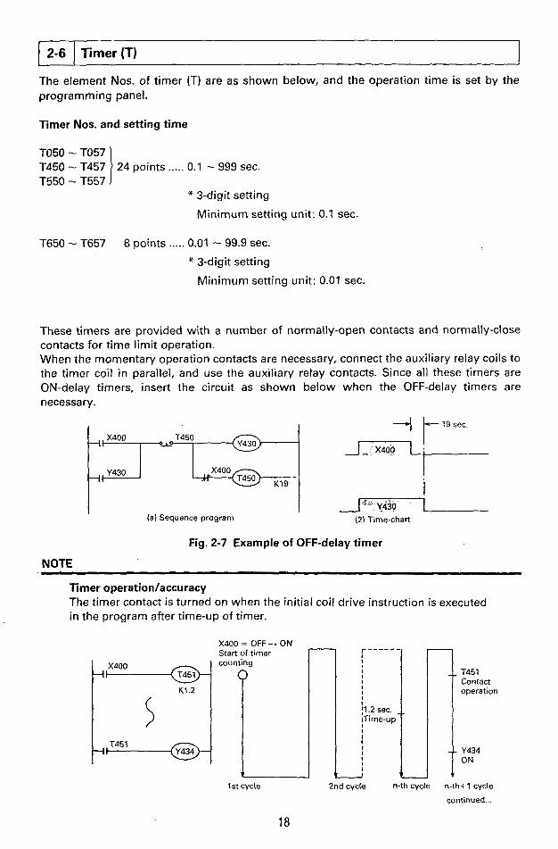
2-6 Timer (T)
Timer Nos. and setting time
TO50 - TO57 T450 - T457 T550 - T557
T650 - T657
24 points ..... 0.1 - 999 sec.
* 3-digit setting
Minimum setting unit: 0.1 sec.
8 points ..... 0.01 - 99.9 sec.
* 3-digit setting
Minimum setting unit: 0.01 sec.
These timers are provided with a number of normally-open contacts and normally-close contacts for time limit operation. When the momentary operation contacts are necessary, connect the auxiliary relay coils to the timer coil i n parallel, and use the auxiliary relay contacts. Since all these timers are ON-delay timers, insert the circuit as shown below when the OFF-delay timers are necessary .
I ( a ) Sequence program
+ t-lgSec --?----
i (2) Time-chart
Fig. 2-7 Example of OFF-delay timer
NOTE
Timer operation/accuracy The timer contact is turned on when the initial coil drive instruction is executed in the program after time-up of timer.
X400 Start of = OFF timer - ON n r - - - - - - j
T45 1 Contact operation
Y434 ON
1 h 2nd cycle n-th cycle n-th+l cycle
continued ... 1 st cycle
18

Consequently, the operation accuracy of timer contact can be roughly given by the following formula;
+TO T -0.1 (or 0.01)
T: Timer setting time (sec.) 0.1 : In the case of 0.lsec. timer
TO: Execution cycle (sec.) 0.01 : In the case of 0.Olsec. timer
!
. . , .. :.. .*, .. . , j . . ... .... :.,:,.,:\ ,:.i;.
19

2-7
The element Nos. for counter are as shown below, and the operation point is set by the programming panel. It is also possible to handle the setting value of the digital switch as that of counter. The digital switch setting value can be handled as the setting value of the counter by the use of functional instruction to be described further on. In either case, these counters are backed up by the battery to hold the current value even in the event of power failure. Where the counter value needs not to be retained, it is necessary to reset the function by the use of initialize pulse M71.
Counter (C)
(1) 3-digit down counter (C060-067. C460-467, C560-567, C662-667 ... 30 points in total)
X400 Resetinput + ~
+ I RST I
?
M7 1 c460
' K9 +I
X401 Count input Settin5 + I . O ~ T value
Counter
C460
Counter output contact
+t
(a) Batch program
RST( C460
Reset coil
Counting coil
X401 Count input /
f @ K9
Setting value
Counter output contact
(b) Divided program
Fig. 2-8 Counter circuit
The counter circuit allows the execution of batch program or division program as shown in Fig. 2-8 (a) and (b). In either case, the counter is reset by initialize pulse M71 when the operation is started, causing the current counter value to be equal to setting value "9". The current counter value is decremented each time the count input is turned from OFF to ON. When the value reaches "0" , the output contact C460 is turned on. The output contact and current value register are changed as follow;
Output contact Output contact turns on when the current value becomes "0" (at the time when OUT C460 instruction is executed,) and turns off when the reset coil is turned on (at the time when RST C460 instruction is executed).
20

Current value register The setting value is written in the current value register at the time when OUT C460 instruction is executed (count input may be ON or OFF) while the reset coil is operating. The current value is decremented by "1" when the reset coil is inoperative and the count input is turned from OFF to ON. The value will not be decremented after the value of "0" in the case of 3-digit counter.
I,,X402-El I X402 ,M72 FIFl OUT - looms
Clock
When the input X402 is turned on in Fig. 2-9 (a), the counter C461 starts counting the operation of 100ms clock pulse M72. When the count value reaches'the set- ting value K600 (60 seconds), the con- tact C461 is turned on.
I If the input X402 is turned off, the counter is reset and the output contact is turned off at the same time.
I (a) Example of 60-sec. timer
Fig.2-9
I RST 1 I LI X403 5 - I I S X402 M72 AElyl 'OUT
Clock
(bi 60-sec. timer (addition of time before and after power failui
Fig. 2-9 Timer using counter
! 60 sec.
C461
An independent reset input X403 is used in the case of Fig. 2-9 (b). If the power fails during the counter operation, therefore, the counter opera- tion is interrupted, and the counter re-starts the operation after the power restoration. When the total time before the power failure and after ?he power failure becomes to reach 60 seconds, therefore, the output contact C461 will be turned. on.
,e I
C461
As described above, the counter may be also used as a timer. 10ms clock pulse M73 may be used as count input, however, care needs to be taken to the following points in this case;
NOTE
Counting of 10ms clock pulse To detect the ON/OFF pulse with a pulse width 5ms, it is necessary that the execution cycle of the programmable controller is less than 5ms. Even when the execution cycle exceeds 5ms, however, it i s possible to count the pulse of lOms by programming same counting instruction (OUT instruction) of the counter dispersedly so that the operation time during the period is less than 5ms.
21

000 l + ~ + - - - @ ) ~ ~ As a gudeline, the counting circuit
M70 operation a _ _ _ _ _ H M470 _____________.
is programmed in increment of 200 steps as shown at left.
200
(2) 6-digit UP/DOWN counter
The counters C660, C661 are used in pairs for a 6-digit UP/DOWN counter. The 6-digit counter can be used selectively for high-speed counter mode for counting of high-speed pulse (2kHz. max.) or ordinary counter mode.
Ordinary counter mode (internal counting mode)
(Pair counter of C660 lower 3 digits, C661 upper 3 digits)
When M470 is turned off, C660 and
x500 Reset output RST I C660 -
'50' Count input
K123
+-I K456 I pA@-l Output contact
C661 are turned to internal counting mode.
The counter appears to be an UP coun- ter when M471 is turned on and a DOWN counter when M471 is turned off.
If RST instruction is provided to C660, C661 is reset automatically.
Set upper 3 digits first.
Set lower 3 digits later.
Y430 is turned on when current value of C660 and C661 reaches "0".
t
Fig. 2-10 6-digit counter (internal counting mode)
When the reset coil of the counter is actuated, not only the output contact C660 is turned off, but also the setting value is read in the current value register when the counting instruction (OUT C661 or OUT C660) is executed later. (Reading is executed whether the count input is ON or OFF). When the reset coil becomes inoparative, the current value is changed by one each time the count input X501 is turned from OFF to ON. (123456 -+ 123457 A 123458 for UP count and 123458 4 123457 ... 0 for DOWN count). The output contact C660 is turned on and is held when the current value of counter is changed from "000001" to "0" (DOWN count) or from "999999" to "0" (UP count). Different from the 3-digit counter, the current value is increased/decreased according to the counting input operation ,after output contact C660 is turned on. It is so designed that the shift-upkhift-down flag M473 is set especially when the count value changes from "999999" to "O"(UP count) or from "0" to "999999" (DOWN count). Under the above internal counting mode, the countable pulse frequency may be restricted by response lagging due to input signal filter, influence of execution cycle by programm- able controller, etc. in the same manner as 3-digit counter. Q
, . 22
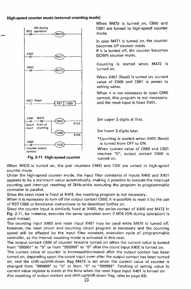
High-speed counter mode (external counting mode)
ON during M70 operation -I+
X402 -i+
X403 -I+
X401 Reset _ _ 1 1 ____----_-_----- { - I - - - - -
X400 M472 - l H k Count Start of K123
&-- input counting
K456
C660 --I+ Counter output contact
Fig. 2-1 1 High-speed counter
When M470 is turned on, C660 and C661 are turned to high-speed counter mode.
In case M471 is turned on, the counter becomes UP counter mode. If it is turned off, the counter becomes DOWN counter mode.
Counting is started when M472 is turned on.
When X401 (fixed) is turned on, current value of C660 and C661 is preset to setting value.
When i t is not necessary to open C660 contact, this program is not necessary, and the reset input is fixed X401.
Set upper 3 digits at first.
Set lower 3 digits later.
*Counting is started when X400 (fixed)
When current value of C660 and C601 reaches "0", output contact C660 is turned on.
is turned from OFF to ON.
When M470 is turned on, the pair counters C660 and CG61 are iurned to high-speed counter mode. Under the high-speed counter mode, the input filter constants of inputs X400 and X401 appears to be a minimum value automatically, making it possible to execute the interrupt counting and interrupt resetting of 2kHz.while executing the program in programmable controller in parallel. Since the reset input is fixed at X401, the resetting program is not necessary. When it is necessary to turn off the output contact C660, it is possible to reset it by the use of RST C660 or functional instructions to be described further on. Since the counter input is similarly fixed at X400, the series contact of X400 and M472 in Fig. 2-11, for instance, executes the same operation even if M70 (ON during operation) is used instead. The counting input X400 and reset input X401 may be used while M470 is turned off, however, the reset circuit and counting circuit program is necessary and the counting speed will be affected by the input filter constant, execution cycle of programmable controller, as the internal counting mode is activated in this case. The output contact C660 of counter remains turned on when the current value is turned from "000001 " to "0" or from "999999" to "0" after the count input X400 is turned on. The current value of counter is increased/decreased after the output contact has been turned on, depending upon the count input even after the output contact has been turned on, and the shift-upkhift-down flag M473 is set when the current value of counter is changed from "999999" to "0" or from "0" to "999999". Fetching of setting value to current value register is made at the time when the reset input input X401 is turned on. (For resetting of output contact and shift-up/shift-down flag, refer to page-83).
23
. ,
_ . . . , . , . . . . . . i , . .. ..... .... ..,,:>.: .><,,
-->.
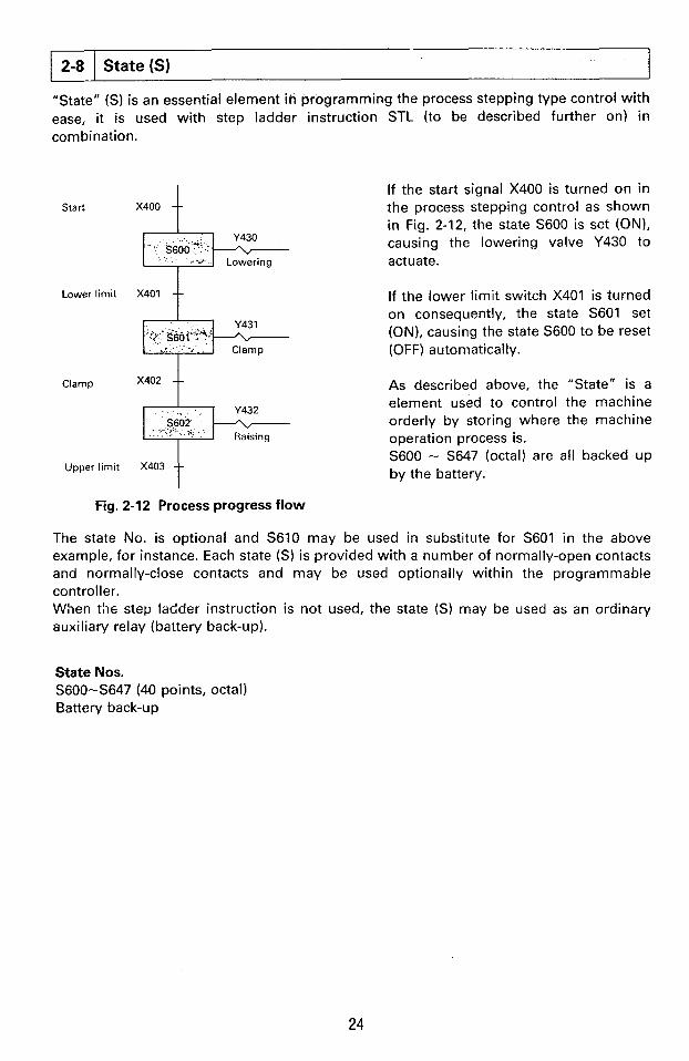
2-8
Start X400 t
State (S)
q q 2 y Lowering
Lower limit X401 t
x402 t Clamp
5602
Upperlimit X403 t
If the start signal X400 is turned on in the process stepping control as shown in Fig. 2-12, the state S600 is set (ON), causing the lowering valve Y430 to actuate.
If the lower limit switch X401 is turned on consequently, the state S601 set (ON), causing the state S600 to be reset (OFF) automatically.
As described above, the "State" is a element used to control the machine orderly by storing where the machine operation process is. S600 - S647 (octal) are al l backed up by the battery.
Fig. 2-12 Process progress flow
The state No. is optional and S610 may be used in substitute for S601 in the above example, for instance. Each state (S) is provided with a number of normally-open contacts and normally-close contacts and may be used optionally within the programmable controller. When the step ladder instruction is not used, the state (SI may be used as an ordinary auxiliary relay (battery back-up).
4
State Nos. S600-S647 (40 points, octal) Battery back-up
24
LD (load)
a i . , - -- .-..- LDI (load inverse)
OUT (out)
& OUT , I
,, X401 4 1
% LDI
I T450 - 0
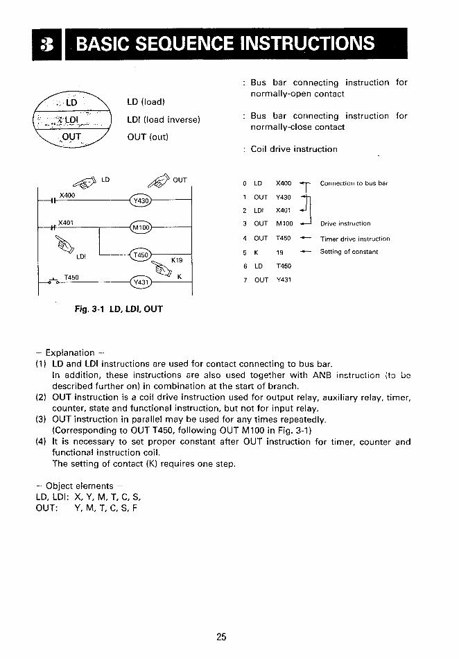
Fig. 3-1 LD, LDI, OUT
- Explanation -
Bus bar connecting instruction for normally-open contact
Bus bar connecting instruction for normally-close contact
Coil drive instruction
LD
OUT
LDI
OUT
OUT
K
LD
OUT
Connection to bus bar
X4G:
M100 Drive instruction
T450 - 19 - Setting of constant
T450
Y431
Timer drive instruction
r:rr !i
LD and LDI instructions are used for contact connecting to bus bar. In addition, these instructions 8re also used together with ANB instruction it3 be described further on) in combination at the start of branch. OUT instruction is a coil drive instruction used for output relay, auxiliary relay, timer, counter, state and functional instruction, but not for input relay. OUT instruction in parallel may be used for any times repeatedly. (Corresponding to OUT T450, following OUT MI00 in Fig. 3-1) It is necessary to set proper constant after OUT instruction for timer, counter and functional instruction coil. The setting of contact (K) requires one step.
- Object elements - LD, LDI: X, Y, M, T, C, S, OUT: Y, M, T, C, S, F
25
!

I
AND (And)
ANI (And inverse)
Y433 X403 Ll h' I
AND
Fig. 3-2 AND, ANI
: Series connecting instruction for nor- mally-open contact
: Series connecting instruction for nor- mally-close contact
LD
AND
OUT
LD ANI
OUT
AND
OUT
X402
M101 --- Series contact
Y433
Y433
X403--- Series contact
MlOl
T451+- Series contact
Y434--- Continuous out
- Explanation - (1) AND and ANI instructions are used for series connection of one contact.
The number of contact to be connected in series is not limited, and the instruction can be used for any time in succession.
(2) The execution of OUT to other coil through the contact after the execution of OUT instruction is called "Continuous OUT". (OUT Y434 in Fig. 3-2) The continuous OUT as described above may be used for any times repeatedly if only the order of circuit design is correct.
- Precaution -
It is possible to drive the coil through the contact T451, following OUT M101 as OUT Y434 shown in Fig. 3-2,
} :y33a<403 , e l , 1 - 7
however, it can not be so programmed reversely as shown in Fig. 3-3.
Fig. 3-3 Wrong circuit
The number of series contact and continuous OUT to use is not limited, however, there is a limitation in the graphic programming panel, printer function, etc. It is recommended to use less than 10 contacts and one coil for one line, and less than 7 lines.
- Object elements - AND, ANI: X, Y, M, T, C, S
26

OR (Or)
OR1 (Or inverse) ITOR Y435
Y435 X407 X410
Parallel connecting instruction for normally-open contact
Para I le I connecting instruct ion for normally-close contact
0 LO
1 OR
2 OR1
3 OUT
4 LDI
5 AND
6 OR
7 ANI
8 OR
9 OUT
z:i J 1 Parallel connection
M102
Y435
Y435
21 1 Parallel connection
X410
M l l O
M102
!
Fig. 3-4 OR, OR1
- Explanaition - (1) OR and OR1 instructions are used for parallel connection of one contact.
Use ORB instruction to be described further on when connecting the series rircc;it (in which more thart two contacts ar connected in series).
(2) OR and OR1 instructions are connected in parallel to the step including the former LD and LDI instructions. The number of parallel connection is not limited.
- Precaution -
Fig. 3-5 Parallel connection point
- Object elements -- OR, ORI: X, Y, M, T, C, S
27
The parallel connection by OR and OR1 instructions are basically connected to the former LD/LDI point. After the execution of ANB instructions to be described later, however, it is connected to LD and LDI points before.
--..

!
Q
: Parallel connection instruction for branch circuit
I
Desirable program Undesirable program 1
0 LD X400 - 0 LD X400
1 AND X401 1 AND X401
I I 2 LD X402 2 LD X402
ORB
'Series circuit block I
Fig. 3-6 ORB
3 AND X403 3 AND X403 - 4 LDI X404 4 ORB
5 LDI X404 5 AND X405
5 AND X405 6 ORB t-
6 ORB -7 CRB c-
7 OUT Y436 a OUT ~ 4 3 6
- Explanation - (1) The circuit in which more than two contacts are connected is called "Series circuit
block". When connecting the series circuit block parallelly, USE LD and LDI instructions for the start of branch, and ORB instruction for the end of branch.
(2) ORB instruction is an independent instruction like AN6 instruction, etc. which is not accompanied by any element No.
- Precaution - (1) Where a number of parallel circuits are used, there is no limitation in the number of
parallel circuit to use if ORB instruction is used for each block. (2) ORB instruction may be used collectively, however, bear in mind that the number of
LD and LDI instructions to be used repeatedly in this case is limited to less than 8 tiines in ona line. (this programming method is undesirable)
- Object elements - ORB: Independent instruction not accompanied by element No.
28

Y438 - y OR instruction before
OR instruction after ANB ANB instruction
Fig. 3-7 ANB and LD, OR
: Instruction to connect branch start instruction in series to previous cir- cuit
0 LD 1 OR 2 LD
3 AND
4 LDI
5 AND
6 ORB
7 OR
8 ANB
9 OR
10 OUT
X400
X401 zz:z --J Branch start point
X404
X405
Completion of parallel block X406 3- - Serires connection to pre-
vious circuit X403
Y438
> .
I
- Explanation - (1) Use ANB instruction to connect the branch circuit (parallel circuit block) in series to the
previous circuit. Use LD and LDI instructions for the start of branch to connect in series to the previous circuit by the use of ANB instruction after the parallel circuit block is completed.
(2) If the multiple number of parallel circuit blocks are connected in series to the previous circuit in succession, the number of ANB to use is not limited. And instructicn may be used totally, however, it is limited like ORB instruction in the number of LD, LDI instruction to use; (less than 8 times)
- Object elements -- ANB: Independent instruction not accompanied by elements No.
All the basic sequences can be programmed by the use of instructions described so far.
X400 T450 ,,Y440 Io
tM 100 , kX404 , X405 1 :C46O 1 , , X406
P Ll x407 @ K85
29
,. --

0 LD X400 6 ORB 12 AND X406
1 ANI TU50 7 LDI Y440 13 OUT MllO
2 LD MlOO a OR cao 14 AND X407
3 AND X404 9 ANB 15 OUT T452
4 OR1 X402 10 OR Y441 16 K a5
5 AND XU05 11 OUT Y430
Fig. 3-8 Circuit and program example
NOTE
"Program procedure and number of step
( 1 ) Write the circuit with a number of series contact at upper side
(a) Desirable circuit
p---&-@- X400 LD LD AND ORE OUT
X400 X401 XU02 Y430
XU02 X400 X401
Y430
{b) Undesirable circuit
Fig. 3-9 Parallel circuit Extra ORB instruction is necessary in the circuit example shown at the lower side.
(2) Write the parallel circuit at left hand side.
la) Desirable circuit
OR ANB
X400 XU01 XU02 Y430
X402 XU00 x401
Y430
(b) Undesirable circuit
Fig. 3-10 Parallel circuit Extra ANB instruction is necessary in the circuit example shown at the lower side.
30
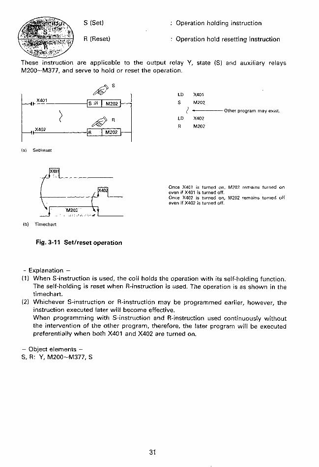
S (Set)
R (Reset)
: Operation holding instruction
: Operation hold resetting instruction
These instruction are applicable to the output relay Y , state (S) and auxiliary relays M200-M377, and serve to hold or reset the operation.
i I b b S 3 M202
I
(a) Setheset
Once X401 is turned on, M202 remains turned on even if X401 is turned off. Once X402 is turned on, M202 remains turned off even if X402 is turned off.
LD X401
S M202
I - Other program may exist.
LD X402
R M202
(b) Timechart
Fig. 3-1 1 Setireset operation
- Explanation - (1) When S-instruction is used, the coil holds the operation with its self-holding function..
The self-holding is reset when R-instruction is used. The operation is as shown in the timechart.
(2) Whichever S-instruction or R-instruction may be programmed earlier, however, the instruction executed later wil l become effective. When programming with S-instruction and R-instruction used continuously without the intervention of the other program, therefore, the later program will be executed preferentially when both X401 and X402 are turned on.
- Object elements - S, R: Y, M200-M377, S
31
. .:

.. .. .. ..
!
pLs I
l + k F ? ? . - - - V G - ~ (a) Use of PLS output
: Differential output instruction
( M 1 0 4 y
M205 M205
0 LD X401
1 PLS M103
2 LD X402
3 PLS M104
4 LD M103
5 S M205
6 LD M104
7 R M205
(bl Timechart
Fig. 3-12 Example of pulse output circuit
- Explanation - (1) When PLS instruction is used for auxiliary relay M, the output contact is operated only
for one execution cycle. (2) The instruction may sometimes be used for reset input of counter or shift register,
input of setheset instruction input of, data instruction, etc. (3) Fig. 3-12 shows circuit which setshesets M205 when X401 and X402 are rise (OFF +
ON). (4) If PLS instruction is jumped by the jump instruction during pulse output, the pulse
output is held turned on.
- Object elements - PLS: MI00 - M377
t 32
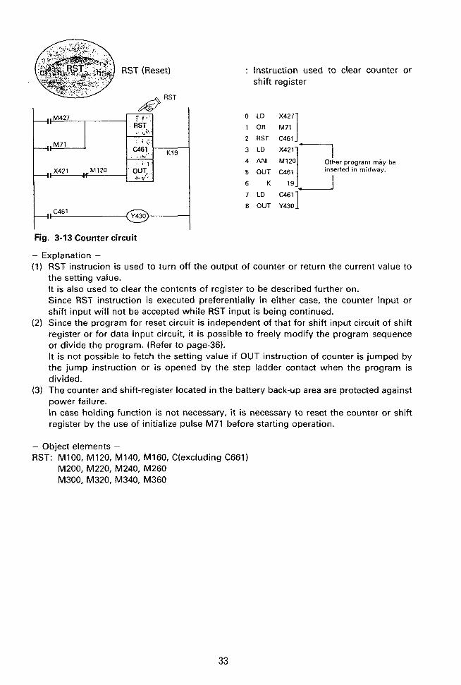
RST (Reset)
I # RST
K19
Fig. 3-13 Counter circuit
- Explanation -
: Instruction used to clear counter or shift register
!
0 LD 1 OR E] 2 RST C461
inserted in midway.
8 OUT Y430
(1) RST instrucion is used to turn off the output of counter or return the current value to the setting value. It is also used to clear the contents of register to be described further on. Since RST instruction is executed preferentially in either case, the counter input or shift input will not be accepted while RST input is being continued.
(2) Since the program for reset circuit is independent of that for shift input circuit of shift register or for data input circuit, it is possible to freely modify the program sequence or divide the program. (Refer to page-36). It is not possible to fetch the setting value if OUT instruction of counter is jumped by the jump instruction or is opened by the step ladder contact when the program is divided.
(3) The counter and shift-register located in the battery back-up area are protected against power failure. In case holding function is not necessary, it is necessary to reset the counter or shift register by the use of initialize pulse M71 before starting operation.
- Object elements - RST: M100, M120, M140, M160, C(excluding C661)
M200, M220, M240, M260 M300, M320. M340, M360
33
.
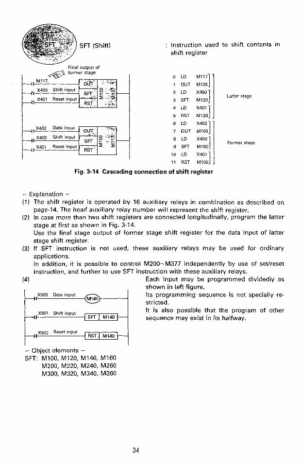
...... SFT (Shift)
Final OutDut of
49 former stage ), M117 o'urt" ', :;A.
Instruction used to shift contents in shift register
1 OUT M120
3 SFT M120
4 LD X401 1 5 RST M1201 J I I 7 OUT MlOO
9 SFT M100
10 LD X4011
11 RST MlOO]
Fig. 3-14 Cascading connection of shift register
Latter stage
Former stage
- Explanation - (1) The shift register is operated by 16 auxiliary relays in combination as described on
page-14. The head auxiliary relay number will represent the shift register. (2) In case more than two shift registers are connected longitudinally, program the latter
stage at first as shown in Fig. 3-14. Use the final stage output of former stage shift register for the data input of latter stage shift register.
(3) If SFT instruction is not used, these auxiliary relays may be used for ordinary applications. In addition, it is possible to control M200-M377 independently by use of setheset instruction, and further to use SFT instruction with these auxiliary relays.
Each input may' be programmed dividedly as shown in left figure.
(4)
X500 Data input Its programming sequence is not specially re- stricted. It is also possible that the program of other sequence may exist in its halfway.
~ 5 0 2 Reset input RST( M140 P
- Object elements - SFT: M100, M120, M140, MI60
M200, M220, M240, M260 M300, M320, M340, M360
34

MC (Master control) : Common series contact, connecting
MCR (Master control reset) : Reset instruction for MC instruction
in st ru ct io n
-I1 e MC T ( i J X MC MlOO
The MC contacts such as MC M100, M C M101, etc. are one normally-
MC f 3 D 2.
e E Q
c
--I IC) Use of MClMCR instructions
I+' Fig. 3-15 Multiple output branch circuit
35
(LDI) instruction to the original bus bar. .

The program example for MC and MCR instruction is shown in Fig. 3-16.
, , X406
I ,,x407
MCRl MlOl E
X400 ,,X401 ---It
'F 4
MlOO e ---I X404
--I X405
- Precaution -
0 LD X400
1 AND X401
2 OUT MlOO
3 LD X402
4 OR X403
5 OUT MlOl
6 MC MlOO
7 LD X404
8 OUT Y430
9 LD X405
10 OUT Y431 >
20 MC MlOl
21 LO X406
22 OUT Y432
23 LD X407
24 OUT Y433
1
30 MCR MlOl
31 LD X410
32 OUT Y434
When the master control instruction is used for MANUAUAUTO sequence changing, be careful not to execute the double output. (Bear in mind that the double output will occur if Y430 is programmed under AUTO mode and Y430 is also programmed under MANUAL mode). Use the jump instruction to be described further on for the execution of double output.
- Object elements - MC, MCR: MI00 - MI77

: Non-processing instruction
AND-+NOP ANI-NOP
(a) Shorted contact
Ed (b) Short in entire previous circuit
OR-NOP
ORI-NOP
(c) Cut-off in circuit
I (dl Cut-off in entire previous circuit
b - ! LD-NOP
( e ) Longitudial connection to previous out
Fig. 3-17 Modification of circuit by NOP instruction
- Explanation - (1) If NOP instruction is inserted in the cource of program, it is possible to minimize the
step number change when rnodifying/adding the program. In addition, it is possible to modify the circuit by replacing the instruction already written, for NOP instruction.
(2) Bear in mind that changing LD, LDI, ANB, ORB, etc. to NOP instruction will cause the circuit configuration to be greatly changed.
(3) All instrcutions will apear to NOP when the program all clear is executed.
- Object elements - NOP: Independent instruction not accopanied by element No.
!
37
..l,- .. .. . .

...I. c
4 CJP (Conditional jump)
EJP (End of jump)
: Jump start instruction
: Jump destination designation instruc- tion
This jump instruction is prepared as a instruction not to execute a part of program. The jump destination numbers are 64 points ranging from "700" to "777" (octal No.).
1 Program-B, . . 4 I Jump
CJP-I 701
@ K19
I EJP %
Execution of program-A + Each output of program43 is held at pre-jump condition. Program execution time is reduced in this case.
Execution of program4 + Fig. 3-18 CJP, EJP
0 LO 1 CJP
2 LD
3 3L;T
4 LD
5 OUT
6 LD
7 OUT
8 K
9 LO
10 RST
1 1 LD
12 OUT
13 li
14 EJP
X412
701 c- Jump starts when X412 is turned on. X413
V441 Remain OWOFF condition before jump. Y430
M102
M l l O
T455
19
X40 1
C46 1
X402 - Count operation is
C461
78
Timer will not operate even if M I 10 is turned on after jump. (Refer to Fig. 3-20).
interrupted during jump, and current value is held
70 1
Fig. 3-19 Jump circuit
When OUT, RST, SFT instructions of counter or shift register are programmed dividedly, care needs to be paid to the operation caused by dividing these instructions to different jump area.
38
- Object Nos. - CJP, EJP: 700 - 777

- Explanation -.
CJP I 704 f--
I, ,,X501
pry Fig. 3-20 Timer and jump
In case X414 is turned on for jumping while X451 and X416 are turned off, the timers T450 and T650 wil l not operate.
If X414 is turned on for jumping while the timer is counting and X415 and X416 have been already turned on, tiowever, each timer will operate as follows;
1 ) T50-T57, T450-T457, T550-T557 (0.1 -sec. timer)
The timers interrupt time counting, and continue time counting after Jump has been reset.
2) T650-T657 (0.01-sec. timer)
Time counting is executed continuously, however, the output contact will not operate upon elapse of timer setting.
When the jump is reset, the output con- tact is turned on at the time of coil instruction execution.
In case the same OUT instruction is used in the jump instructions which operates inconsistently, OUT instruction under ex- ecution is treated preferentially.
If X417 (a-contact) is turned on in Fig. 3-21, Y444 will operate according to the operation of X501.
While X417 (a-contact) is turned off, Y444 will operate according to the operation of X500.
Fig. 3-21 Double coil and jump
If the pulse instruction during the execution of pulse output is jumped by jump instruction, the pulse output is kept generated.
! , '
i
I
39
U P rVO?"? - 4-F2i-i
I-- x310
EJP I 706
EJP I 705
-1 EJP I 707
I EJP' I 702": c
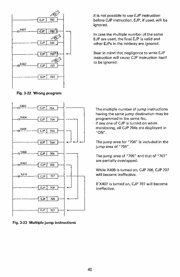
Fig. 3-22 Wrong program
1 CJP I 704 Pxm3 CJP I 704 t+-
Fig. 3-23 Multiple jump instructions
It is not possible to use EJP instruction before CJP instruction. EJP, if used, will be ignored.
In case the multiple number of the same EJP are used, the final EJP is valid and other EJPs in the midway are ignored.
Bear in mind that negligence to write EJP instruction will cause CJP instruction itself to be ignored.
The multiple number of jump instructions having the same jump destination may be programmed in the same No. If any one of CJP is turned on when monitoring, all CJP 704s are displayed in "ON " .
The jump area for "706" is included in the jump area of "705".
The jump area of "705" and that of "707" are partially overlapped.
While X406 is turned on, CJP 706, CJP 707 will become ineffective.
If X407 is turned on, CJP 707 will become ineffective.
1
40
c U P 700 1- I
I EJP 703 I
J 1111
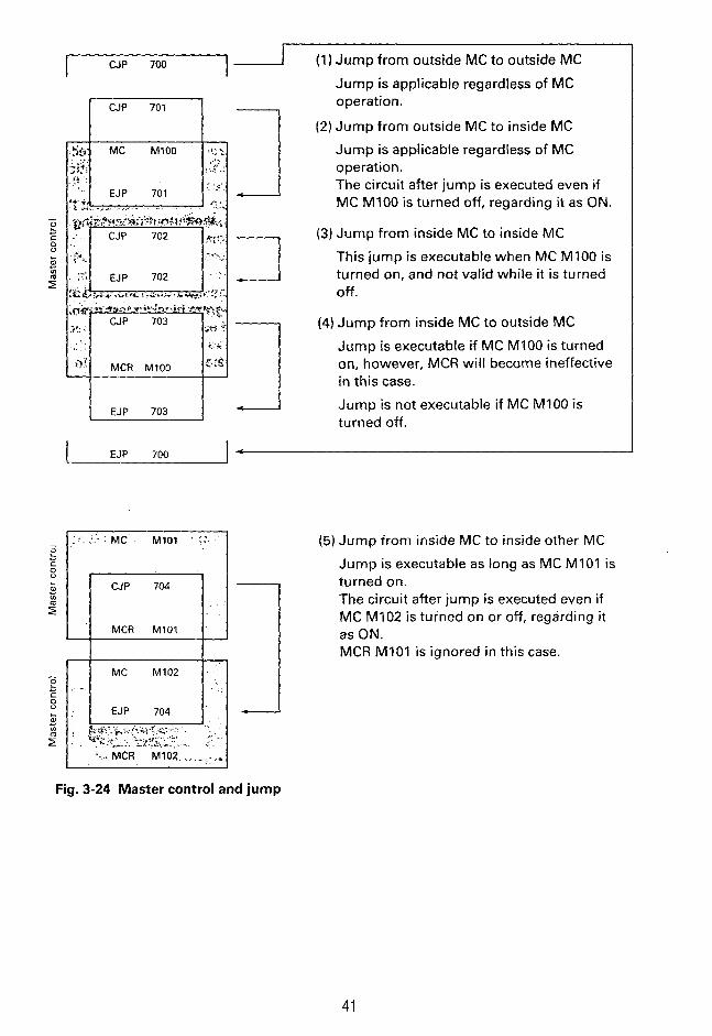
(1 1 Jump from outside MC to outside MC
Jump is applicable regardless of MC operation.
(2) Jump from outside MC to inside MC
Jump is applicable regardless of MC operation. The circuit after jump is executed even if MC MI00 is turned off, regarding it as ON.
(3) Jump from inside MC to inside MC
This jump is executable when MC MI00 is turned on, and not valid while it is turned off.
(4) Jump from inside MC to outside MC Jump is executable if MC MI00 is turned on, however, MCR will become ineffective in this case.
Jump is not executable if MC MI00 is turned off.
I EJP 700 1 4
J Fig. 3-24 Master control and jump
41
(5) Jump irom inside MC to inside other MC Jump is executable as long as MC MI01 is turned on. The circuit after jump is executed even if MC MI02 is turned on or off, regarding it as ON. MCR MI01 is ignored in this case.
,

.... END (End)
I I
. . I Output processing
Fig. 3-25 END instruction
: Instruction used at end of program
The programmable controller will execute the input processing, program execution and output processing repeatedly. If END instruction has been written at the end of program, the output processing is executed immediately without the execution of succeeding extra steps.
If END instructions has been inserted at the end of each program block in test running, the operation of each block can be checked sequentially. In this case, delete the END instruction sequentially after checking the operation in previous circuit block.
- Object elements - END: Independent instruction not accompanied by element No.
NOTE
Proceed programming from left to right and upperside to lower side.
I . . . . \ . ...., . . ., . . . . .......... e - I . . . . .
. . . . . .
The object elements for each instruc- tion and element No. of each PC are listed at the paragraph "Summary".
42

The entier sequence program can be roughly divided into "General sequence" centered on the mode selection, "Manual sequence" and "Automatic sequence". This section describes the contents of step ladder instruction and handling of the above three sequences.
Example of process stepping type control
___L Right travelling
c--- Left travelling The step ladder instruction can be directly used for automatic sequence. relay ladder for manu- al sequence and designated cir- cuit for mode selection respec- I
I
t Tg , .
Lower1 ng . . - c Clamp
c -+ Unclamp r 3 ' r -;
_.^ ./. I ,
/Work ___- 8 ,
I .. A-point 6-point
Work transfer (A+B) mechanism
43
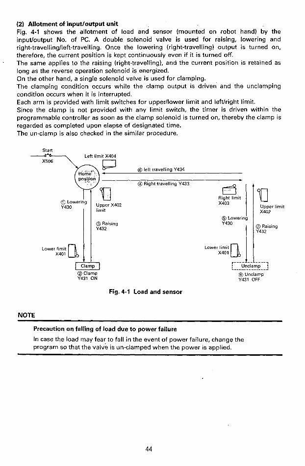
(2) Allotment of input/output unit Fig. 4-1 shows the allotment of load and sensor (mounted on robot hand) by the inputloutput No. of PC. A double solenoid valve is used for raising, lowering and right-travelling/left-travelling. Once the lowering (right-travelling) output is turned on, therefore, the current position is kept continuously even if it is turned off. The same applies to the raising (right-travelling), and the current position is retained as long as the reverse operation solenoid is energized. On the other hand, a single solenoid valve is used for clamping. The clamping condition occurs while the clamp output is driven and the unclamping condition occurs when it is interrupted. Each arm is provided with limit switches for upper/lower limit and leftlright limit. Since the clamp is not provided with any limit switch, the timer is driven within the programmable controller as soon as the clamp solenoid is turned on, thereby the clamp is regarded as completed upon elapse of designated time. The un-clamp is also checked in the similar procedure.
t
Start Left limit X404
@ left travelling Y434
@ Right travelling Y433 b
Right limit X403 @) Lowering
Y430 Upper X402 limit
@ Raising Y432
@ Lowering
y430 I I
@Clamp Y431 ON
Fig. 4-1 Load and sensor
NOTE
Lower limit X401 I
Upper limit X402
@ Raising Y432
Precaution on falling of load due to power failure
In case the load may fear to fall in the event of power failure, change the program so that the valve is un-clamped when the power is applied.
I
i
44

(3) Allotment of operation input The example of the machine operation modes are as follows. The operation panel is made up as shown in Fig. 4-2 for this purpose. The startlemergency stop sequences are provided outside the programmable controller and the power to the external loads is turned on/off according to these sequences.
MANUAL I-
Single operation -
Mode to turn on/off each load by each pushbutton
Home position returning -
Mode to return the machine to its home position automatically when the home position returning pushbutton i s depressed
Stepping
Mode to advance the operation by each process at each time the start button is pressed
One-cycle operation -
When the start button is depressed at the home position, the cne-cycle operation is executed automatically, and the machine is stopped a t the home position thereafter. If the stop button is depressed in the course of operation, the machine is stopped at the process. If the start button is depressed, the operation is continued from the process and stopped automatically at the home position.
Continuous operation -
When the start button is depressed a t the home position, the continuous operation is performed repeatedly.
If the stop button is depressed, the machine moves to the home potion and then stops position.
Since the single manual operation is also available by the use of programming panel, it is not always necessary to prepare the pushbutton for all loads.
45
_.-\

..
!
7 Stepping Home
position returning Home position
1-cycle operation
Continuous Operation operation
X504 @ Pushbutton used to turn on/off load power source for external circuit
Start ax,,, Emergency ;I stop
0 retur;i;;, X505
Single operation
Raising Left travelling Unclamp X500
X405 X406 X407 Lowering Right travelling Clamp
@ @ @ X410 X411 X412 Stop X507
Fig. 4-2 Example of operation panel
(4) Overall sequence configuration The overall configuration of manual sequence (single operation, home position returning) and automatic sequence is as shown in Fig. 4-3. It is recommended to program on the basis of the following figure.
Sinale ~ 5 0 0 operation
- 1
EJP I 700
Home position
CJP I 701
program (Fig. 4-14)
EJP I 701
As shown in Figs. 4-10 through 4-12, program the general sequences such as initialization of state, start of state transfer, and state transfer inhibition, etc.
When the single operation mode is selected and +X500 is opened, single operation program to be de- scribed further on will be executed. While the other mode is selected, % X500 is closed, by which the program is jumped.
If the home position returning mode is selected, and X501 is opened, the home position returning program to be described later will be executed.
Under the other modes, 4 G X 5 0 1 is closed and the program is jumped, causing the operation not to be ex-
CONTINUED ecuted.

fM102
Automatic sequence is programmed on the basis of Fig. 4-6 “State trandition diagram”.
]=J----- _ _ _ _ - - _ _ _ _ _ - _- - _- - - - - -- - -- - --
The automatic program will not be executed until the start button is depressed.
This program will not be necessary when the machine is re-started from the home position after power res- toration.
automatic program; Make it a rule to express the automa- tic program by the state transition diagram shown in Fig. 4-6 or step ladder diagram shown in Fig. 4-16. When the circuit diagram is printed out by the printer, it will be express- ed in step ladder diagram format.
Fig. 4-3 Overall sequence
47
1 ! i
!
/--,
.. .-
-I._.
4-2
, , .:. . . . , ... , .. . ,.., : ; . ' . .
Automatic sequence program
I
I
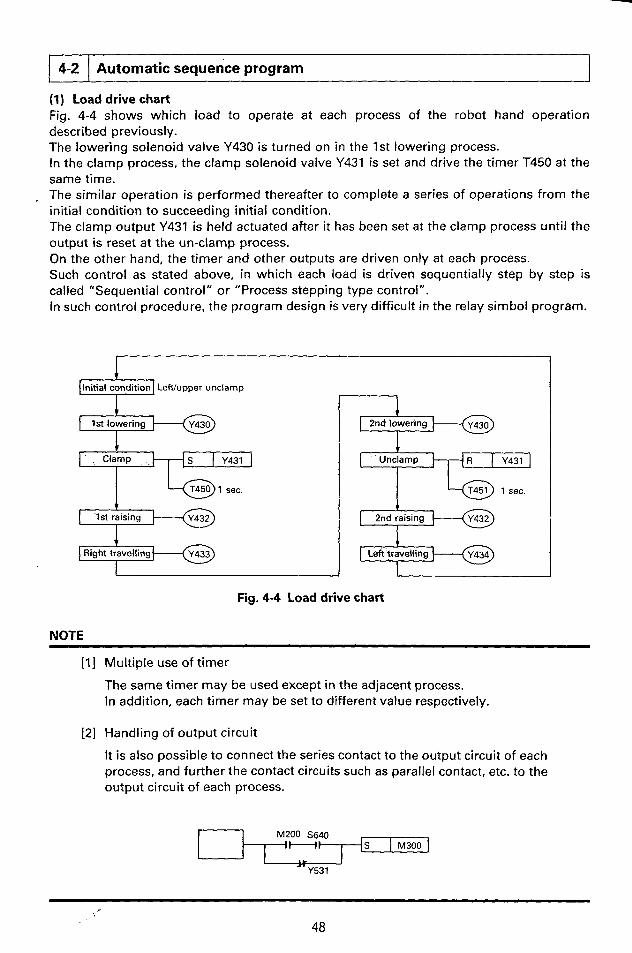
(1) Load drive chart Fig. 4-4 shows which load to operate at each process of the robot hand operation described previously. The lowering solenoid valve Y430 is turned on in the 1st lowering process. In the clamp process, the clamp solenoid valve Y431 is set and drive the timer T450 at the same time. The similar operation is performed thereafter to complete a series of operations from the initial condition to succeeding initial condition. The clamp output Y431 is held actuated after it has been set at the clamp process until the output is reset at the un-clamp process. On the other hand, the timer and other outputs are driven only at each process. Such control as stated above, in which each load is driven sequentially step by step is called "Sequential control" or "Process stepping type control". In such control procedure, the program design is very difficult in the relay simbol program.
Initial condition LeWupper unclamp I
1st lowering
S I Y431
l b T450 1 sec.
I - - 1st raising
4 __
1 I Right travellind
2nd lowering 'SF&] I - T451 1 sec.
Fig. 4-4 Load drive chart
NOTE ~~~~ ~ ~~ ~~~~~
[ I ] Multiple use of timer
The same timer may be used except in the adjacent process. In addition, each timer may be set to different value respectively.
121 Handling of output circuit
It is also possible to connect the series contact to the output circuit of each process, and further the contact circuits such as parallel contact, etc. to the output circuit of each process.
f M200 S640 H I S I M300
Y531

(2) Transfer condition chart Fig. 4-5 shows on what conditions each process should be transferred. When the start button is depressed on the initial condition, the process is transferred to the 1st lowering process. When the arm reaches the lower limit position as the lowering solenoid valve operates, the lower limit switch X401 is turned on, and the process is transfeured to the clamp process. Since the timer T450 is executed together with the clamp output, the process is transferred to the succeeding 1st raising process when the contact of the timer is turned on thereafter. The operation is performed similarly thereafter to complete a series of process transfer.
1 . .
I
I 1
-- X404: Left limit switch
Initial condition i--' t X506: Start button
'1st !owering Li" r l - X403: Right limit switch
2nd lowering I + 1 t X401: Lower limit switch I t X401: Lower limit switch
T405: Clamp confirmation timer t T451: Unclamp confirmation timer I I f Zhdi%ing' I + t X402: Upper limit switch I I t X402: Upper limit switch
Right travelling 0 .Lek travelling I * Fig. 4-5 Automatic operation flowchart
NOTE
Handling of transfer circuit
When normally-close contact is used for transfer condition, write it as X400, for instance. It is also possible to use series or parallel circuit of various contacts as transfer condition.
-
MlOO y430D- 5620
Transfer is executed when Y430 is turned on, or MI00 is turned on (M100: OFF) and S620 is turned on.
49
! . i '
.--...

% !
i
1
i i
(3) State transition diagram Fig. 4-6 shows a state transition diagram combining the load drive chart (Fig. 4 4 ) with the transfer condition chart (Fig. 4-5), each process of which is alloted with state No. The state No. may be used in optional No. ranging from "S600" to "S647", but it is not necessary that the No. is serial as shown in the following diagram. As described above, it is possible to program simply by preparing a state transition diagram for the machine operation specifications without the necessity to design the conventional relay sequence.
4
Initial state
Y430 Lowerjng
T450 T450 K1
+&-a Raising
X 4 0 2 t Upper limit
Right travelling
X403-t Right limit I
I
I + = Raising
Fig. 4-6 State transition diagram
NOTE
[ I ] Initial state
The initial state indicating the initialized condition is shown with double frame, and set with the home position returning instruction as shown in
. Fig. 4-10.
[21 Transfer start
The special auxiliary relay M575 used for transfer start is so designed as to be turned on when the start pushbutton is depressed as shown in Fig. 4-1 1. It is recommended to connect the home position condition in series.
[3] Program example
The above program will be given as follows;
STL
LD
S
STL
OUT
LD
S
STL
S
OUT
S600
M575
S601
S601
Y430
X401
S602
5602
Y431
T450
K 1
LD T450
S S603
STL 5603
OUT Y432
LD X402
S S604
STL S604
OUT Y433
LD X403
S S605
STL S605
OUT Y430
LD X401
S S606
STL S606
R Y431
OUT T451
K 1
LD T451
S
STL
OUT
LD
S
STL
OUT
LD
S
5607 S607
Y432
X402
S610
S610
Y434
X404
5600
50

(4) Function of state r.-
1 There may exist a series of /Darallel contact circuit.
'/ I \\' X D 3 0 + State Sh.':. v 1 --State Sm Y*
'// I \ \ ' - I - / . T, C, S, etc. may be used
(a) Waiting for XOOU ON operation (b) Operation after X 3 9 3 ON operation
Fig. 4-7 Function of state
When the state (Sn) is turned on, the output YAAA and YO00 are turned on (Fig. -a). If the transfer condition X U 0 0 is turned on even momentarily, the state (Sm) is turned on and Y*** is turned on at the same time. (Fig. -b) At the same time, Sn become inoperative-and the output Y G A A is turned off. In this case, however, the output Y C X X driven by the set instruction holds its operation. Both states are turned on during the momentary period (one-execution cycle) when transferred from the state (Sn) to state (Sm).
1 Operation processing p+@-l .i+ Drive processing I State Sn i
Xddu Transfer condition
&I Succeeding step
(a) State transition diagram
Transfer destination condition
. .-\ i !
(b) Step ladder diagram
Fig. 4-8 State and STL instruction
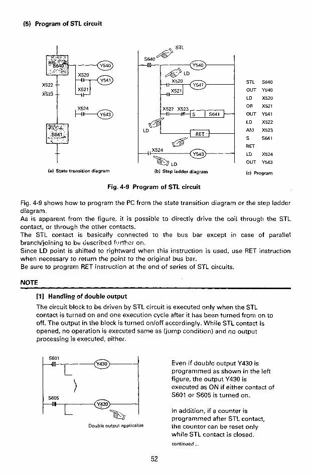
The above figure (a) represents one example of state transition diagrams. Each state is provided with three functions of "Drive processing for each load", "Designation of transfer destination" and "Designation of transfer condition". This represents the transition diagram by the step ladder diagram (Fig. -b) in relay sequence format, in which the instruction of STL is used for contact (-i I-). LD (LDI) instruction is programmed for the initial contact leading to the STL contact. If the state (Sm) is set through STL contact (Sn), Sn is reset automatically. STL instruction is provided with the function to reset the origin state automatically.
51

[2] Handling of state
STL instruction is effective only to the state-S, and the number of STL instruction applicable to the same state is limited only to one time. (e xc I u d i ng " Pa ra I I e l/j o i n in g " to be ex p I a i n ed f u rt h e r on 1. It is possible to apply the instructions such as LD, LDI, AND, ANI, OR, ORI, OUT, S, etc. to the state-S in the same manner as ordinary auxiliary relays. Only S instruction and R instruction are effective for the output instruction for state after STL contact.
LD X401
AND Y430 OUT S600 LD 5600 OR MlOO
ANI S601
OUT Y431
[3] State and MC/CJP instructions
MC instruction and MCR instruction cannot be used after STL contact. CJP instruction and EJP instruction may be used. When jumped from CJP701 to EJP701 in the figure below, it is regarded as ON and the PC execute the succeeding circuit even if STL contact of the circuit block is turned off.
Un-applicable
I ',\ 1 ,,' Master control ,?,K;> 7 0 2 J
Un-applicable
continued .._
53
I

[4] Un-reset transfer procedure for transfer origin .
It is also possible to transfer to the other state without resetting the state automatically. If the transfer condition XOUO is turned on while the state (Sn) is turned on, the state (Sm) is turned on, by which the state (Sn) is reset automatically. If the transfer condition XOOO is turned on in advance while the state (Sn) is operating, however, the state (Sk) is turned on, but the state (Sn) will not be reset. It is possible to use the contact (Si) of other state for the transfer condition from the state (Sm) to state (S i )
54

[ 4 3 1 General sequence of mode selection, etc.
(1) State initialization
Home position returning Home position
Single X500 operation - X500 operation
Home position
Initial state
Simultaneou reset of intermediate state
I LG&---lJ K103
Fig. 4-10 State initialization
(1) Setting of initial state The initial state (S600 for Fig. 4-10) showing the machine initialized condition is set when the home position returning button is depressed under home position returning mode, and reset under single operation mode.
NOTE
The initial state is pi-ovided with the following roles;
button
switch
When the start button is depressed in the left-hand side figure, the operating state is transferred from S600 to S601 and the transfer is progressed sequentially there- after as the machine operation progresses. When the final process operation is com- pleted later, S600 is set again.
Even when the start button is falsely de- pressed during a series of operations, another start-up is not possible, as S600 has become inoperative.
( 2 ) Resetting of intermediate state The state at the intermediate process needs to be normally reset at manual operation (single operation, home position returning) because the state is backed up by the battery to hold the pre-power failure condition in some cases. Use the function instruction F670, K103 as shown in Fig. 4-10 to reset the intermediate state. In this example, the states S601-S610 are reset at the same time.
55

NOTE
When it is necessary to start the operation continuously from the pre-power failure condition -when the power is restored, the contact M71 programmed in Fig. 4-1.0 is not necessary. In this case, the output relay driven by the set instruction needs to be driven through the auxiliary relays M300 - M377 (battery back-up).
Turned off if power failure occurs during self-holding.
T450 S603
Battery back-up
Operation is retained even if power failure occurs during self- holding.
S602
OFF
K1
T450
RET /ON aher restoration
of power
(2) State transfer start
YY Continuous Self- operation holding Start of transfer
Start
Continuous op'eration
I Upper Left Un-clamp limit limit
W Home position I condition
Fig. 4-1 1 State transfer start-up sequence
56
156001 Initial state 7 Start of transfer
condition
S602 + i

The auxiliary relay M575 operates by depressing the start pushbutton during automatic operation (stepping, one-cycle, continuous operation). Especially while the automatic program is being executed, the self-holding circuit operates, and the auxiliary relay M575 holds the operation until the stop button is depressed. On the other hand, the auxiliary relay MI00 is operated to check the machine home position. When both M575 and MI00 are turned on, the transfer is started from the initial state.
(3) State transfer inhibit When the special auxiliary relay M574 is actuated while the state transfer control is executed by the use of step ladder instruction, the state automatic transfer is inhibitted.
X506 -I\ PLS I M l O l Start
X507 X503 MlOl -1-1 I a' Stop 1-cycle
operation State transfer fl inhibit
X502 -4'
Single
circuit
When the start button is depressed, MI01 generates the pulse output, caus- ing M574 to turn off.
When the stop button is depressed during one-cycle operation, M574 self- holds, the operation is stopped at cur- rent process.
When the start button is depressed, the operation is restarted from the process.
M574 operates all the time under step- ping mode, in which the state transfer is inhibitted.
When the start button is depressed, state transfer prohibition is reset momentarily, and proceeded to the suc- ceeding process.
The state transfer is inhibitted under manual mode (single operation, home position returning). The state transfer inhibit is reset at the time when the start button is depressed after the manual mode reset.
Fig. 4-12 State transfer prohibition sequence
57
M574 self-holds by the initialize pulse M71 when the programmable controller starts, by which the state transfer will be inhibitted until the start button is depressed.
!
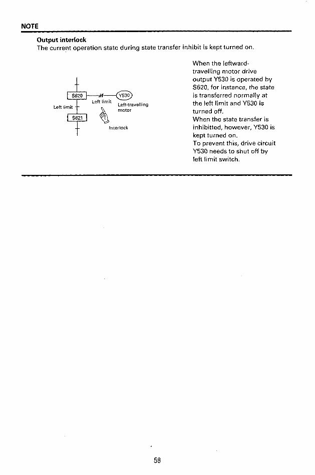
....
j
NOTE
Output interlock The current operation state during state transfer inhibit is kept turned on.
Left limit Left-travelling motor Left limit
Interlock
When the leftward- travelling motor drive output Y530 is operated by S620, for instance, the state is transferred normally at the left limit and Y530 is turned off. When the state transfer is inhibitted, however, Y530 is kept turned on. To prevent this, drive circuit Y530 needs to shut off by left limit switch.
I
58
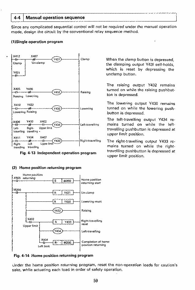
4-4
(1 )Single operation program
i Manual operation sequence
X405 Y430 -i- Raising Lowering
Y432 - - - travelling travelling - - travelling travelling
(2) Home position returning program
I Home Dosition
Raising
Lowering
Left-travelling
Right-travelliny
X505 returning
U n-cla mp
I Lowering reset
. Raising
Upper limit
R..' . ~200. Completion of home X404
Left limit position returning
When the clamp button is depressed, the clamping output Y431 self-holds, which is reset by depressing the unclamp button.
The raising output Y432 remains turned on while the raising pushbut- ton is depressed.
The lowering output Y430 remains turned on while the lowering push- button is depressed.
The left-travelling output Y434 re- mains turned on while the left- travelling pushbutton is depressed at upper limit position.
The right-travelling output Y433 re- mains turned on while the right- travelling pushbutton is depressed at upper limit position.
Fig. 4-14 Home position returning program
dnder the home position returning program, reset the non-operation loads for caution's sake, while actuating each load in order of safety operation.
59
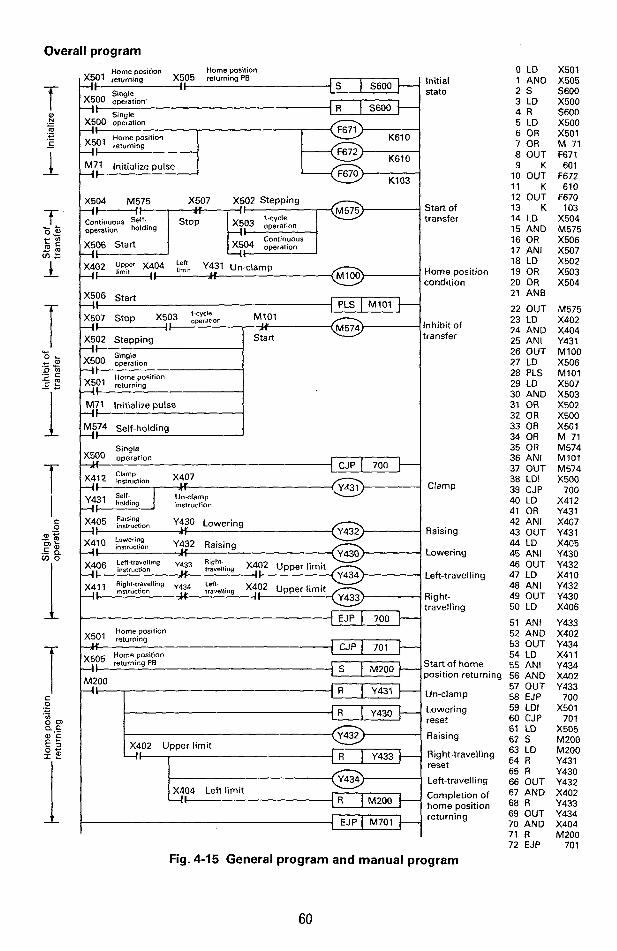
Overall program
4
? f
Home posilion Home position X501 returning X50
X500 opzaiion 4 1 I
M71 Initialize pulse - i I
K103
X507 X502 Stepping X504 M575 - Start of transfer
operation holding
X506 Start
Home position condition
X402 ygyy X404 Kt Y431 Un-clamp 41 I ,
X507 Stop X503 -4-1 X502 Stepping
I, Inhibit of operation M,':'
Start transfer
xjbl Home position
-41 returning
M574 Self-holding
Single X5OO operation I,
Clsmp
J
y i 2 E E t i o n ,
1;431 holding instruction 'z ' j Self- Unclamp
Raising y 5 insrrudlon Y430 Lowering
Raising
Right- travelling
x41 Rjght-travelling y43c Lett-
4 I 'nslruC'ion
I EJP 1 700 H Home position
Start of home position returning
Raising
Right-travelling reset
Lefbtravelling
home position
0 LD 1 AND 2 s 3 LD 4 R 5 LD 6 OR 7 OR 8 OUT 9 K
10 OUT 11 K 12 OUT 13 K 14 LO 15 AND 16 OR 17 ANI 18 LD 19 OR 20 OR 21 ANB
22 OUT 23 LD 24 AND 25 ANI 26 OUT 27 LD
29 LD 30 AND 31 OR 32 OR 33 OR 34 OR 35 OR 36 ANI 37 OUT 38 LDI 39 CJP 40 LO 41 OR 42 ANI 43 OUT 44 LD 45 ANI 46 OUT 47 LD 48 ANI 49 OUT 50 LD
51 ANI 52 AND 53 OUT 54 LD 55 ANI
28 PLS
56 57 58
AND OUT EJP
59 LDI 60 CJP 61 LD 62 S 63 LD 64 R 65 R 66 OUT 67 AND 68 R 69 OUT 70 AND 71 R 72 EJP
X501 X505 5600 X500 5600 X500 X501 M 71 F671 60 1
F672 610
F670 103
X504 M575 X506 X507 X502 X503 X504
M575 X402 X404 Y431 MlOO X506 M101 X507 X503 X502 X500 X50 1 M 71 M574 MlOl
Q M574 X500
700 X412 Y43 1 X407 Y431 X405 Y430 Y432 X410 Y432 Y430 X406
Y433 X402 Y434 X411 Y434 x402 Y433
700 X501
701 X505 M200 M200 Y431 Y430 Y432 X402 Y433 Y434 X404 M200
701
Fig. 4-15 General program and manual program
60

? Q
e
NOTE
S I Y431 I I I
S603 4&
X402 Upper limit -4s 1 S604 E S604 --nu--
k - ,
W -,S 1 S61D
I RET I
73 LD 74 OR 75 OUT
Aastercontrol 76 MC 77 STL 78 LD 79 AND 80 S 81 STL a.2 OUT 83 LD 84 S 85 STL 86 S
.owering 87 OUT 88 K 89 LD 90 s 92 OUT 93 LD 94 s 95 STL 96 OUT
98 s 99 STL
100 OUT
102 s 103 STL 104 R
:lamp 91 STL
iaising 97 LD
light-travelling 101 LD
.owering 105 OUT 106 K 107 LD 108 S
Jn-clamp log STL 110 OUT 111 LD 112 s 113 STL 114 OUT 115 LD 116 S 117 RET 118 MCR
' 119 END
7aising
-eft-travelling
nitial state
X506 M102 M102 M102 5600 M575 MlOO 5601 5601 Y430 X401 5602 5602 Y431 T450
1 T450 5603 5603 Y432 X402 5604 5604 Y433 X403 5605 5605 Y430 X401 5606 5606 Y431 T45 1
1 T451 5607 5607 Y432 X402 5610 5610 Y434 X404 5600
M102
Fig. 4-16 Automatic program (for step ladder diagram)
Re-starting after power failure When the operation is re-started from the home position after the restoration of power, the steps 73 - 76 and 118 will not be necessary. When the operation is re-started from the current condition, on the contrary, these program will become necessary to inhibit the automatic output until the start button is depressed. In this case, however, it is necessary to delete OR-M71 of the 7th step, as the intermediate state will not be reset.
61

"--
i
? .: ..,: .: : , . ,.. ' j ... .
!
I
1 ; i !
I ! i
4 4-5 Handling of multiple flows
(1) Multiple flow configuration
I I
,$ If Selective branch/ Parallel branch/ joining joining
Single flow
(a (b) (c)
Fig. 4-17 Multiple flow configuration
Q
v)
.- Y
The micro programmable controller F, series will allow various flows operating independ- ently by one PC.
(a) Single flow It is not necessary to number the state Nos. in order of process. (The same applies to the others). In addition, it is possible to interlock the flow transfer conditions by the state of other flow to execute the inter-related control.
(b) Selective branchljoining The flow is used for selective branch of multiple flows, of which program example is as shown in Fig. 4-18.
(c) Parallel branch/joining The flow is used for simultaneous branch of multiple flows, of which program example is as shown in Fig. 4-19.
(d) Skiphepetition The flow is used for skiphepetition of part of flow, of which program example is as shown in Fig. 4-20.
Any of the complicated flows can be expressed by the use of the above (a) through (d) in com bina tion.
62
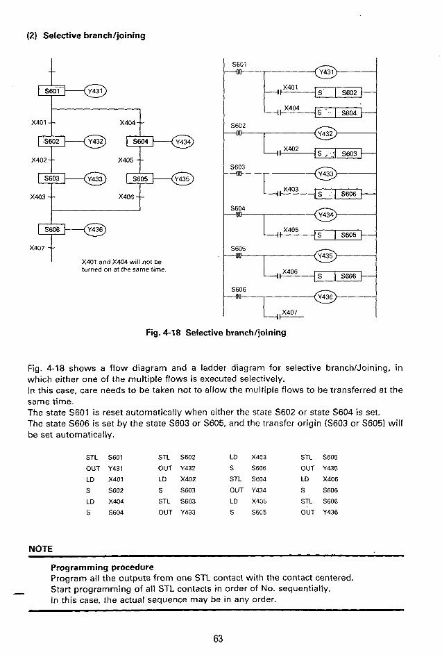
(2) Selective branch/joining
1 t
... ̂ _ F-0
X402 X405
S603
X403 X406
X407
X401 and X404 will not be turned on at the same time.
I
S603
I
S604 - 4 0 - I
S605 --OD
Fig. 4-18 Selective branch/joining
Fig. 4-18 shows a flow diagram and a ladder diagram for selective branch/Joining, in which either one of the multiple flows is executed selectively. In this case, care needs to be taken not to allow the multiple flows to be transferred at the same time. The state S601 is reset automatically when either the state S602 or state S604 is set. The state S606 is set by the state S603 or S605, and the transfer origin (S603 or S605) will be set automatically.
STL S601 STL S602 LD X403 STL S605
OUT Y431 OUT Y432 S S606 OUT Y435
LD X401 LD X402 STL S604 LD X406
S S602 S S603 OUT Y434 S S606
LD X404 STL S603 LD X405 STL S606
S S604 OUT Y433 S S605 OUT Y436
NOTE
Programming procedure Program all the outputs from one STL contact with the contact centered. Start programming of all STL contacts in order of No. sequentially. In this case, the actual sequence may be in any order.
-
63

..: . I .. ..:. . . . , I ,;.. , . . . . ... '
X402
(3) Parallel branch/joining
-- X403 --
t FF S603
-011
=--IJq$?&- S605
4 0
- U c - - - a M \ IS I S606 S603 S605 X404
S606 +Q
X404 t "9"- x405 t
Fig. 4-19 Parallel branch/joining
Fig. 4-19 shows an example in which the multiple flows are branched simultaneously and then joined. The state S606 is set after the states S603 and S605 have been both operated to reset the transfer origins S603 and S605. In case STL instruction is used continuously (limited to less than 8 times), it means the series connection. Only the SET instruction for state is effective to the coil following the series connection. RET instruction returns to bus bar for one use.
STL S601 LO X402
OUT Y431 S 5603
LD X401 STC S603
S S602 OUT Y433
S S604 STL S604
STL S602 OUT Y434
OUT Y432 LO X403
S S605
NOTE
STL
OUT
STL
STL
LD
S
STL
OUT
S605
Y435
S603
S605 Continuous use X404 TSI (for parallel confluence) S606
S606
Y436
~ ~-
Programming procedure Program the S (set) instruction for joining side states all together. Accordingly, STL603 and STL605 are programmed two times in the case of above example.
6 64
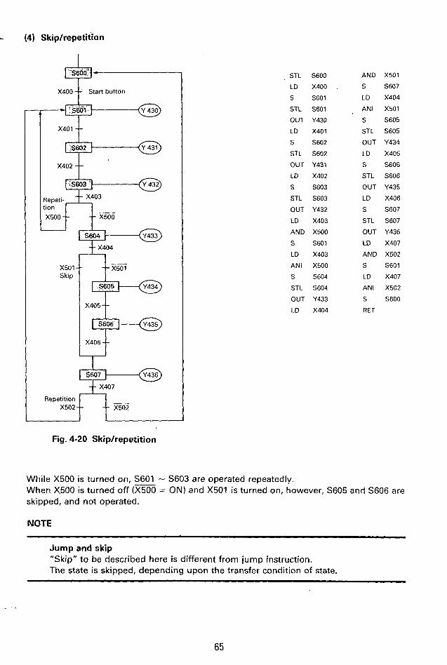
- (4) Skiphepetition :J.'
Repetition X502 --
X400 f Start button
__ -- X502
STL 5600
LD X400
S S601
STC S601
OUT Y430
LD X401
S S602
STL S602
OUT Y431
LD X402
S 5603
STL S603
OUT Y432
LD X403
AND X500
S S601
LD X403
ANI X500
S 5604
STL 5604
OUT Y433
LD X404
AND X501
s sa7
LD X404
ANI X501
S S605
STL S605
OUT Y434
LD X405
S S606
STL S606
OUT Y435
LD X406
S S607
STL S607
OUT Y436
LD X407
AND X502
S S601
LD XU07
ANI X502
S S600
RET
While X500 is turned on, S601 - S603 are operated repeatedly. When X500 is turned off (m = ON) and X501 is turned on, however, S605 and S606 are skipped, and not operated.
NOTE
Jump and skip "Skip" to be described here is different from jump instruction. The state is skipped, depending upon t h e transfer condition of state.
65
. L b
I !
. .
I

'- ... 4- +--@ S601.
-!- X401
x403
I I ,+-@ S605,
x406 t
S601
S602
S603
C460 , , X405 1 ,I -1s I 5602
1 .S605 X404 s .
RET
S605 4 0
, , X406
Fig. 4-21 Repetition operation by counter
In this example, the portion of states S602 - S604 is operated for five times repeatedly, depending upon the setting value of counter C460, and then transferred to the state S605.
STL
OUT
LD
S STL
OUT
LD
S
NOTE
S601
Y431
X401
S602
S602
Y432
x402
S603
STL
OUT
LD
S
STL
OUT
LDI
AND
S
S603
Y433
X403
S604
S604
Y434
C460
X405
S602
LD
AND
S RET
LD
FIST
LD
OUT
K
c460 STL S605
X404 OUT Y435
S605
Tal S605
C460
S604
C460
d
!
Handling of counter circuit Bear in mind that RET instruction is used before the counter circuit program. Unless RET instruction is inserted, the setting value cannot be fetched, as the count input S604 is turned off, resulting in jump operation mode when the counter is reset (S605: ON).
t
66

(5) Program example
T450
# --
Selective branch -- K1
t I
S601-S611 Simultaneous reset
I Parallel branch
T451
T452 K1
K1
T454 --
T455 Parallel/joining
T457
Selectiveljoining
T550 t K3
Fig. 4-22 Compound branchijoining
In case X500 is ON
s600 1 S602 - S603 - S604 - S611 - (Y4301 (Y431) (Y432) lY433) IY530)
(Y434) (Y435) S605 - S606 \
In case X550 is OFF /
\ '
1 S601 S607 - S61@ - S611 S600 (Y430) (Y436) (Y437) (Y5301
I I
!
i
67

NOTE
LD M 7 1
OUT F671
K 601
OUT F672
K 611
OUT F670
K 103
S S600
STL S600
LD X400
S S601
STL S601
OUT Y430
OUT T450
K 1
LD T450
AND X500
S S602
LD T450
ANI X500
S S605
S . 5607
STL S602
OUT Y431
OUT T451
K 1
LD T451
S S603
STL S603
OUT Y432
OUT T452
K 1
LD T452
S S604
STL S604
OUT Y433
OUT T453
K 1
LD T453
S S611
STL S605
OUT Y434
OUT T454
K 2
LD T454
S S606
STL S606
OUT Y435
OUT T455
K 1
STL S607
OUT Y436
OUT T456
K 4
LD T456
S S610
STL S610
OUT Y437
OUT T457
K 2 STL S606
STL S610
LD T455
AND T457
S S611
STL S611
OUT Y530
OUT T550
K 3
LD T550
S S600
RET
~~ ~ ~ ~ ~~
[l] Limit on number of branchijoining There is no limit in the number of selective branch. (Actually, the number of state is limited). In the parallel branch, however, there are the following limitations at the joining point;
When the joining state S622 is operated in the following figure, it is possible to reset automatically up to 8 points of transfer origin, however, the remaining states require the program resetting.
+, ,+, --------------- +I ,+, ,+ X400 t
S622 is set through STL S610, STL S611 ... STL S617, LD X400 AND S620, AND S621.
68
4!

[2] Overlapped use of state It is possible to use the same state No. by discriminating the multiple flows which will not operate simultaneously with jump instructions.
-+ State S6004647 I 2nd flow
In the flows divided by jump instruction as shown at left figure not to operate simul- taneously the overlapped state No. can be used.
i
The state having been used before jump needs to be reset completely.
i
[31 Time-out sequence The approach for generating emergency stop output for case when the operation time of each state has exceeded the normal value is as described in the following;
Set the operation time at a little longer than the normal transfer
It is possible to use the timer of the same No. for non-adjacent
[ T k K2.5 ~ time required.
LS
LS
L++---o T551 K3
t
/ /
state.
!
69
I Indication of emergency I stop output
I

.-
, . . . : . .... I. .... 1 ' .... .
The use of basic sequential instructions and step ladder function described in the previous chapters so far will make it possible to prepare almost all the ordinary application programs for relay replacement. The F, series programmable controller is provided with additional 22 kinds of functional instructions to allow the preparation of special programs such as high-speed processing and data transfer, special application of counter, etc., thus allowing it to be applied in increased application fields. This chapter describes these functional instructions.
(1) Expression format
MlOO -4- Input
LD OUT
K
condition by OUT Setting coil ... Setting of
K-NO. K
M 1 0 0
F 6 7 1
000 F 6 7 2
:1 &l A ? I
F 6 7 5
cmc3cI F 6 7 0
K x. Y * Execution coil ... Setting of * * * instruction
OUT
K OUT
contents by K-No.
Program input, setting coil and the execution coil sequentially. The number of setting coil to use may vary, depending upon the contents of instruction, and some instructions may not require any setting coil.
Fig. 5-1 Basic configuration of functional instruction
The expression format of the functional instruction is as shown in Fig. 5-1, of which condition setting meaning for the setting coil may be different, depending upon each functional instructions. Each contact such as X, Y , M, T, C, S, etc. within the programmable controller is used for the drive input, by which it is possible to use not only the single contact but also circuit made up of multiple number of circuits in combination. The execution time for functional instruction needs to be given by adding the execution time of setting coil to that of execution coil (Refer to Tables 6-1 and 6-2 in summary). In either case, execution time may vary between when the input i s turned on and when it is turned off.
NOTE
[ l ) Role of setting coil The execution coil defines the contents of functional instruction by K-No. following the execution coil, whereas the setting coil serves to further designate the detailed condition on the basis of each functional instruction contents, and may provide the different meaning, depending upon the functional instruction used.
121 In case the functional instructions have been used several times and each setting coil has already been set, the setting coil for later functional instructions are omissible under the condition that the setting conditions are the same.
70

I
! f--
5-1 Input/output high-speed processing instruction b 1
K102 Input
Object elements; XOOO-X027 X400-X427 X500-X527
This instruction is not provided with any setting coil, and can be estab- lished only by the execution coil.
This instruction is not provided with any setting coil, and can be estab- lished only by the execution coil.
When the input (MI00 in above example) is turned on, ON/OFF condition of al l input terminals is fetched newly in the input image memory at the time when this instruction is executed. This function is not effective while the input is turned off. The refresh operation is the same operation as the batch input processing to be executed prior to the execution of the program. It is possible that the reading to the image memory may remain turned off due to response lagging of input filter even if the input terminal is turned on.
I
Object elements: YO30-YO47 Y430-Y447 Y530- Y547
If the input (MI00 in the above example) is turned on, ON/OFF condition of output image memory is transferred to the output latch memory at the time when this instruction is executed. This function is not effective when the input is turned off. This refresh operation is the same as batch output processing executed after completing the execution of the program and the actual output is turned on upon elepse of response lagging of output relay after the output latch memory is turned on.
71

.. ...
t
. . . . . . . . . 1 I
, . , . . .
1 !
Application example-I High-frequency input processing
+ ,.$ Input processing t
operation
ON during operation
-I "Oitout orocessina ._ I-
Output processing
Input processing
output processing
Input processing
Program the input all-point refresh instruc- tion (input processing) and output all-point refresh instruction (output processing) with the overall program divided into almost equally in time.
With the program, it becomes possible to output the execution result to the output terminal as quickly as possible after execu- tion of the program on the basis of as new input terminal information as possible.
In this case, the same input can become ON or OFF within the one cycle of the program. In the output in which the program is ex- ecuted under the different block as shown below, it is necessary to provide an interlock.
I:== Interlock Program-A
Program-E Interlock
Fig. 5-2 Additional input/output processing Unless the interlock is provided, Y530 and
NOTE
Y531 may be turned on at the same time.
Input/output response lagging
When the input-all-point refresh instruction or output all-point refresh instruc- tion is programmed "n" times equally in the program of which execution cycle is "To", the input/output response lagging is as follows.
Output image I OFF memory ...... ?N.,%'*/. 1 Input terminal
To -+ k1.s. than L+ n e 1 +I,,, than- n;1
Filter output ... ..: ... OFF output latch memory
-I k Td 4 I- 4 kless t h a n 3 less than - TO n + l
..... ON OFF 1 . .+..* ON I OFF Output Input image memory terminal
Tf .............. Response time of
To
Td ............. Mar. lagging time to input filter output latch
- .......... Max. lagging time n + l n-1 output latch
To - .......... Max. lagging time to
Fig. 5-3 Input response lagging Fig. 5-4 Output response lagging
To shorten the response lagging due to input filter, it is possible to use the following functional instruction F670 K l O l
72

Object elements: X400-X407
Input filter constant setting (K = 0-60ms integral value)
Refresh of input X400-X407 input memory
When the input (MI00 in the above figure) is turned on, input information for 8 points of X400-X407 will be newly fetched, and then written in the input image memory when this instruction is executed. The function is not effective while the input is turned off. The response lagging for ON/OFF of image memory against ON/OFF of the input terminal is determined by the value K of the setting coil F671. An RC filter is normally provided with the input of the programmable controller to prevent the noise interference, by which the response lagging of approx. 10ms may be brought about. On the other hand, the inputs X400-X407 are provided with a digital filter which can be modified by the program. When making consideration to prevent any noise interference in the input wiring, therefore, the constant of the filter may be reduced to any small value in decrement of 1 msec. (Actually, the minimum RC filter is used, and the value will not be reduced to smaller than
Observing the operation of X400 in the example given in the above figure, the followings can be known; (1) The image memory X400 is turned on (or off) when the input terminal X400 has been
turned on (or off) for more than 3msec. before the execution of F670 K l O l instruction. (2) If the input terminal X400 is turned to ON or OFF within 3msec., the image memory
remains unchanged.
200p) .
_ - - - - Input x400 I - . 3 -..t
termtiial k-4 3ms and over H 3ms and over - _ _ _ - Image memory ~ 4 0 0 A,*-
t Execution
t Execution of F670 K l O l F670 KlOl
NOTE ~~
The input signal is fetched with its filter constant of 10ms at the time of input processing before execution of the program.
-
73

I
Application example-2 Emergency output program
K500 X400 -11 I.
-I Output orocessins . -I-
Note: X400-X407 is treated as filter constant of 10ms in the input processing before exection of program.
1 ms
X400-X407 refresh
Emergency program
1 ms
X400-X407 refresh
Emergency program
I----t-------l 6ms and over 6ms
and over
Execute the program with the emergency program for two times in a program of IOms execution cycle dividing into two, shown in the left figure.
Program the partial input refresh in- struction before the emergency pro- gram with the filter constant desig- nated at "Ims".
If the ON time or OFF time of input X400 is more than Gmsec., for inst- ance, the latched output Y430 may be turned off.
In case the partial input refresh in- struction is not used and the emergency refresh program is pro- grammed only one time, the ON time or OFF time of input X400 needs to be more than 20ms due to influence by operation cycle of approx. 10ms and input filter constant of 10msec.
The above described the emergency fetching of input X400. Where the emergency output of out- put Y430 is needed, use the output all-point refresh instruction F670 K102 at the same time.
!
i
74
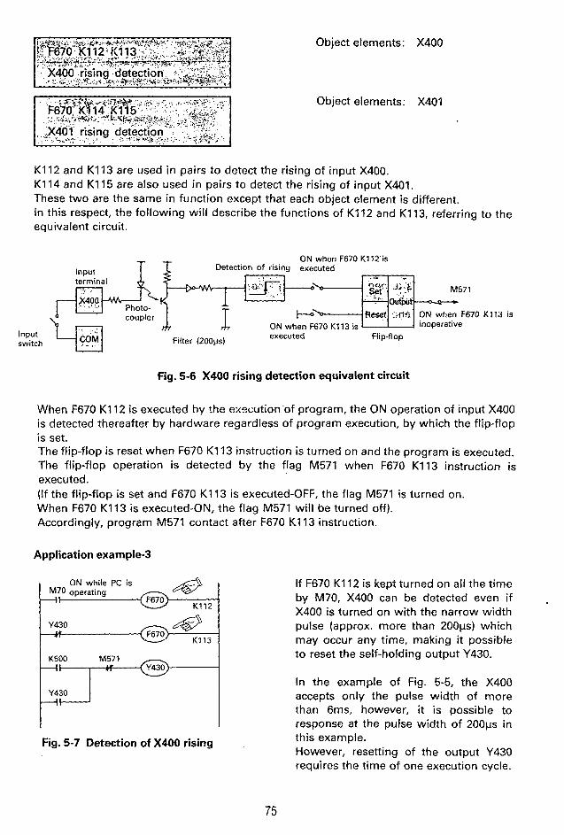
Object elements: X400
Object elements: X401
4 ON while PC is M70 operating @ K 1 1 2 ~
Y430 a& F670 K 1 1 3
K500 M571 I t *
Y430
K112 and K113 are used in pairs to detect the rising of input X400. K114 and K115 are also used i n pairs to detect the rising of input X401. These two are the same in function except that each object element is different. In this respect, the following will describe the functions of K112 and K113, referring to the equivalent circuit.
ON when F670 K 1 1 2 ' i s Detection of rising executed Input
O&f
m inoperative coupler 5, ON when F670 K 1 1 3 is
executed flip-flop Filter (200~s) Input switch
Fig. 5-6 X400 rising detection equivalent circuit
When F670 K112 is executed by !he exocution'of program, the ON operation of input X400 is detected thereafter by hardware regardless of program execution, by which the flip-flop is set. The flip-flop is reset when F670 K113 instruction is turned on and the program is executed. The flip-flop operation is detected by the flag M571 when F670 K113 instruction is executed. (If the flip-flop is set and F670 K113 is executed-OFF, the flag M571 is turned on. When F670 K113 is executed-ON, the flag M571 will be turned off). Accordingly, program M571 contact after F670 K113 instruction.
Application example.3
If F670 K112 is kept turned on all the time by M70, X400 can be detected even if X400 is turned on with the narrow width pulse (approx. more than 2 0 0 ~ s ) which may occur any time, making it possible to reset the self-holding output Y430.
In the example of Fig. 5-5, the X400 accepts only the pulse width of more than 6ms, however, it is possible to response at the pulse width of 200~s in this example. However, resetting of the output Y430 requires the time of one execution cycle.
75
i j
I

-- 5-2
, . . . . . ., . : .
Instructions concerning reset
!
K337 ~
K103
I
Reset end element No. (M337 in this example)
Simultaneous reset of designated range (Reset of Y30-Y47 and M100-M337 in this
Object elements: Y030-Y547 M100-M377 S600-S647
Application example-4 Simultaneous reset of state
The simultaneous reset instruction is used for initial resetting of state and auxiliary relay backed U601
up by the battery and for resetting of element jumped by the jump instruction.
Bear in mind that no resetting is executed when F670 K103 instruction is jumped.
Fig. 5-8 Simultaneous reset of state
Even when the step ladder circuit is jumped by the jump instruction, these states will be reset when the simultaneous reset of state is executed. When the output connected to the step ladder contact needs to be reset at the same time, program the simultaneous reset instruction for output Y at the same time, as such outputs remain at the current situation.
i
76
. c
i

Object element: M473 (shift up/down flag)
Object element: C660 (pair counter)
Reset the shift up/down flag M473 of pair counters 660/661. (Current value will not be changed).
Reset the output contact C660 of pair counters C66OK661. (Current value will not be changed). Input
When the current value reaches "0", the output contact C660 of the pair counters C660/C661 is turned on, thereby the output contact C660 remains turned on even if the current value is changed. F670 K111 instruction is used for its resetting. F670 KllO instruction is similarly used to reset M473 which is set when the pair counters are turned "999999" to "0" (shift-up) or from "0" to "999999" (shift-down). Since these instructions are used to turn off the M473/C660 contacts, the current value of counter will remain un-changed. The output contact C660 may be also turned off by RST C660 instruction. In this case, the current value of counter is preset to the setting value. In addition, M473 may be set when auto-reload (see page 137) is executed, and can be reset by F670 K1:O instruction.
Application example-5 9-digit down counter
X500
X501 reset 49 - I C @ KllO
- iI
7g. 5-9 9-digit down countei
C662
C660 reset
M473 reset
r
9-digit counter can be programmed by using the pair counters C660/C661 as down-counter and by counting the operation of output contact by the use of cascade counter C662.
77
, I I , 8 ,
0 , : !
C660 contact p h

.. .. I
External reset
X401 X501 - - i t __-_____ K--
X502 41 Internal reset
RST I C660
X400 M472 4-t Count input @ KO03 ~
Object element: C660, C661
When the special auxiliary relay M470 is turned on, the pair counters C660 and C661 are turned to high-speed counter mode, by which the X400 becomes count input and the X401 becomes the reset input to execute the interrupt counting and interrupt reset.
If the external reset inhibit instruction is used to reset by the internal program, X401 may be utilized for the other application.
High-speed counter reset inhibit by input X401 K116 Input
0 While the input (M100 in the above example) is turned on, resetting function of the high-speed counters C66OK661 by X401 will be prohibited.
0 If the input X401 is turned on while the input (M100 in the above example) is turned off, the setting value is preset automatically at the current value register of the high-speed counter C600/C601. (Output contact C660 wil l not be changed). This program is not necessary when the reset function of X401 is used al l the time.
Circuit example External reset inhibit
ON while PC is M70 operating
+ I
M70 operating OFF while PC is
X500 Start of counting -I
X501 -1
K116
C660 -I1
Fig. 5-10 High-speed counter
The pair counters C660/C661 are turned to high-speed counter mode.
The pair counters C660/C661 are turned to down-counters.
Counting starts wh.en M472 is turned on, and stops when it is turned off.
When X501 is turned on, automatic rest inhibit by X401.
The same operation will result even if the counter reset circuit (shown with dotted line) may not be programmed. (Output C660 is turned off, causing the setting value to be preset in the current value register).
Upper 3-digit setting value 003 (to be programmed first)
Lower 3-digit setting value 500 (to be programmed later)
C660 contact is turned on at the count of 3500.
The same operation will result even if M70 is used in substitute for X400, X472 in the count input circuit. In this case, the counter will automatically count the number by OFF+ON of X400.
78

5-3 Data (numeral value) transfer instruction t 0 Data transfer
destination : M260-M273
Designation of counter No. (C567) Input
Transfer the current value of counter designated (BCD 3-digit) to M260--M273.
0 Execute the transfer when the input is turned on. When there occurs any setting error in the counter No., the error flag M570 is turned on, but the instruction will not be executed.
0 If the input is turned off, no processing wil l be executed, and the error flag M570 is turned off.
0 The transfer data is of BCD 3-digit, the lowermost digit of which is M260 and uppermost digit of which is M273.
M273 M272 M271 M270 M267 M266 M265 M264 M263 M262 M261 M260
1-F I OFF I OFF I OFF I ON I ON 1 ON I OFF I OFF I ON
I 800 400 200 100 I 8@ 40 20 10 I 8 4 2 1
j 439
- - I
Digit of 1 I
Digit of 100 ’ Digit of 10
i
i
Application exampled Indication of current counter value
Fig. 5-11
I I Current value of C660
I I 1
4 Transfer of current value in C660 to M260-M273 M273
c Y447 Y440
Output of upper two digits of M260-M273 to Y440-Y447
I
Output of current counter value
Since the F, series programmable controller i s not provided with the instruction to transfer - the BCD data (binary decimal) to the output-\/, each bit is output to the external unit by the 3 instruction as shown in Fig. 5-11.
79

Object element: 0 Data source : M260-M273
(BCD 3-digit) 0 Data transfer
destination : Current value register
81
of counter (CO60-667)
Designation of object counter No. (C460) Input
w-1 Write BCD 3-digit data of M260-M273 to the current value register of counter designated. (M260 ... lowermost digiVM273 ... uppermost digit)
Set the transfer data to the auxiliary relays M260-M273 in advance.
M273 M272 M271 M270 M267 M266 M265 M264 M263 M262 M261 M260
\.OFF d5.J I OFF 1 OFF I ON I 'ON I O k ' l OFF 1 Ohi 1 OFF.! 6 N '1 'ON 1 ON+] @ 197
800 400 200 100+80 40 20 10 +8 4 2 1 ___ - -
Digit of 100 Digit of 10 Digit of 1 i- The transfer is executed when the input is turned on. In this case, the output contact of counter will not be changed. In case there occurs any counter No. setting error, or the figure at each BCD digit exceeds "9", the error flag M570 is turned on, and no transfer is executed. In case the input is turned off, no transfer is executed, and the error flag M570 is turned O f f .
80
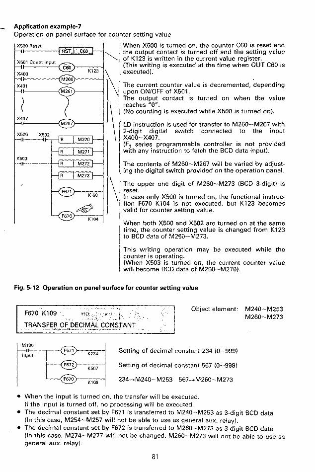
- Application example-7 Operation on panel surface for counter setting value 1
\
X500 Reset I
X501 Count input - I 1 X400 +I X401 -It
\
\
! When X500 is turned on, the counter C60 is reset and the output contact is turned off and the setting value of K123 is written in the current value register.
executed). (This writing is executed at the time when OUT C60 is 1 The current counter value is decremented, depending upon ON/OFF of X501. The output contact is turned on when the value reaches "0". (No counting is executed while X500 is turned on).
LD instruction is used for transfer to M260-M267 with 2-digit digital si/vitch connected to the input X400- X407. (F, series programmable controller is not provided with any instruction to fetch the BCD data input).
The contents of M260-M267 will be varied by adjust- ing the digital switch provided on the operation panel.
The upper one digit of M260-M273 (BCD 3-digit) is reset. In case only X500 is turned on, the functional instruc- tion F670 K104 is not executed, but K123 becomes valid for counter setting value.
When both X500 and X502 are turned on at the same time, the counter setting value is changed from K123 to BCD da?a of N1250-M273.
This writing operation may be executed while the counter is operating. (When X503 is turned on, the current counter value wil l become BCD data of M260-MZ70).
Fig. 5-12 Operation on panel surface for counter setting value
-. ~ Object element: M240-M253 1 .I I M260-M273 .r.',l? . . g:: -. . > ? 1 TRANSFER OF DECIMAL CONSTANT
..-w -4--... . ..-1 -.
Setting of decimal constant 234 (0-999)
Setting of decimal constant 567 (0-999) K567
234-+M240-M253 567-+M260-M273 K109
0 When the input is turned on, the transfer will be executed. If the input is turned off, no processing will be executed.
0 The decimal constant set by F671 is transferred to M240--M253 as 3-digit BCD data. (In this case, M254-M257 will not be able to use as general aux. relay).
0 The decimal constant set by F672 is transferred to M260-M273 as 3-digit BCD data. (In this case, M274-M277 will not be changed. M260-M273 will not be able to use as general aux. relay).
81 I

. . I
i I
! f
. . . . . .,. . , .
I
i
Mi73 c c Mi60
0 1 0 1 1 0 I ' l . ( O 0 1 1 1 O O O O O O O O C O O N - 0 0 0 ~ C O U N r
Application example-8 Changing of counter setting value
(501 iI
m-1 K456
0 0 0 0 0 0 0 0 m u ~ r
M260-M273 (456)
-t Current value register of C460 (See page 891
(500 X503 4-
K460
Fig. 5-13 Counter setting value changing
M260-M273 (7891 - Current value regis:er of C460 (See page 89)
When X500 is turned on, the counter C460 is reset and the output contact is turned off and the setting value of K123 is written in the current value register when OUT C460 instruction is ex- ecuted.
The current counter value is de- cremented, depending upon ON/OFF of X501. The output contact is turned on when the value reaches "0" . (No counting is executed while X500 is turned on).
Note:
Since the F, series prograrnm- able controller is not provided with any setting value register for counter, the constant is transfer- red to the current value register. Make it a rule to execute the transfer before starting the count- ing (during reset).
Initial setting value of counter
I I X500 I X502 I X503 I Setting values
Note: In the above example, the counter IC460) setting value is changed in 3 different ways.
a
82

- w e instruction for current counter value 1 Object element:
Counter (C060-C667 1 BCD data (M260-M273)
-r""""----ti data a t M260-M2;$?:!..
MlOO I
Input
K107 M571 Carry flag
M572 Zero flag --I
+I----@-+ M573 Borrow flag
Use functional instruction F670 K109 for setting of con- stant. (See page-101 ). Use LD instruction for input from the external unit by the use of digital switch. Setting of counter No. C560
Comparison of current counter value of C560 with M260-MZ73
ON: BCD data < Current value
ON: 8CD data = Current value
ON: BCD data > Current value
0 When the input is turned on, the compare will be executed. In case there occurs any setting error of counter No., or error in the BCD data (in case each digit exceeds "9"), the error flag M570 is turned on, and no compare is executed. In this case, M571-M573 are all turned off. In case the input is turned off, no processing is executed, and M570-M573 are all turned off.
M273 M272 M271 M270 M267 M266 M265 M 2 M M263 M262 M261 M260
-1Od ''1 OFF { OFF I ON I OFF I OFF I OFF I ON I ON I 9 5 2 3
___-_ ___ ' J Digit of 1 . I 8o Digit 40 of 2o 1 0 l o +
800 400 200 :+ Digit of 100
Current value of ---e 999 ----- 523 - 000 counter
M571 .ON M573 ON
M572' ON
NOTE
Handling of flag When the compare instruction is used for multiple times, the flag is changed every time the compare instruction is executed.
When it is output to the aux. relay of different No. for each compare data, it is possible to obtain "Great", "Small" or "Coincidence" for each compare instruction.
_-. i
83

,,, _., . . , .. ;;. " : . "
K15
Application example-9 Simple positioning control
Y431 forward output
Y431 - - I t
X404 Count input
K999 4 1
K107 Y431 M573 - 4 H l
Borrow flag
L n .- 8 m
U
I .-
A X403 Start
- Load 3-digit setting value to M260-M273 by the use of digital setting switch connected to the input of X500-X573. (example: 789)
The current value of counter C463 is set to - BCD value (789) of M260-M273. The value will appear to be the total forward running distance. (See page 89).
bM240-M253 15+M260-M273 Set the low-speed setting distance at "15". (See page 96).
- Compare the current value of counter C463 with value of M260-M273 (151.
- Low-speed operation
Fig. 5-15 Simple positioning control
In this example, the motor is operated at two-stage speed of high-speed and low-speed to control the machine movement distance. The total movement distance is set variably by the 3-digit digital switch connected to the input of X500-X513. The low-speed operation distance is set with constant by F670 K109 to generate low-speed output by compare instructions of K670, K107.
84

3 -.
Input @ K560
t c l - - x G - F673
KlOF
M571 Carry flag
M572 Zero flag
M573 Borrow flag
--I\
--It
+t
Object element: <, . I . ... .&.a. .. . ,I +.;G.~i, . . ~ ~ , r g ' :
6 1 :< ....,I. ~ . .:... ,.,;>< NT V@UE
Counter (CO60-CS67) 3-digit decimal, 2 points
I, , i.. ..n"
.IS 1 . :? *x:.r. I .
Designation of counter No. (C560)
Decimal constant (0-999) A
Decimal constant (0-999) 8 (BZA)
Current value of counter designated is compared with constants A, B for output to M571-M573.
ON: B < Current value
ON: B 2 Current 2 A
ON: Current value < A
'
0 Compare is executed in case the input is turned on. In case there occurs any counter No. setting error, the error flag M570 is turned on, and no instruction is executed, and M570-M573 will be turned off.
0 When the input is turned off, no processing will be executed. In this case, M570-M573 will be turned off.
0 For setting value, B needs to be equal to or greater than A. If A is larger than B, A is compared with the current counter value.
Current value of - -- - - + 999 - - - B -- * A ---+ 000 counter
'.M57lcQN I M572-.,ON. 1 M573 ON
Application example-I 0 Driving of load by timechart
7 Current value 5 sec 10 secl5 sec20 sec25 sec30 sec
@OO 50 100 150 200 250 300 of counter
J . . Output Y430 :
Output Y431 I . ... .
Fig. 5-15 shows a sequence diagram for the case when the multiple outputs Y430, Y431, etc, are operated in accordance with timechart as shown above.
85
i
L'
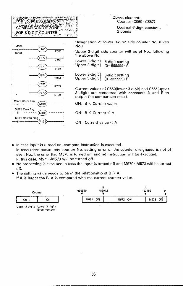
.. .. _-
Cn+l . Cn
Object element: Counter (C060-C667)
Decimal 6-digit constant, 2 points
M571 ON M572 ON M573 ON
input
KO12
K789
K108
M571 Carry flag
M572 Zero flag
Designation of lower 3-digit side counter No. (Even No.) Upper 3-digit side counter will be of No., following the above No. Lower 3-digit 6-digit setting Upper 3-digit (0-999999) A
Current values of C660(lower 3 digit) and C661 (upper 3 digit) are compared with constants A and B to output the comparison result.
ON: B < Current value
ON: B 2 Current 2 A
ON: Current value < A
e In case input is turned on, compare instruction is executed. In case there occurs any counter No. setting error or the counter designated is not of even No., the error flag M570 is turned on, and no instruction will be executed. i r i this case, M571-M573 will be turned off.
0 No processing is executed in case the input is turned off and M570-M573 will be turned off.
0 The setting value needs to be in the relationship of B 1 A. If A is larger tha B, A is compared with the current counter value.
!
0 : 86

NOTE
How to program 6-digit counter
The zone compare instruction for 6-digit counter is effectively used for pair counters C660/C661. Even in the case of general 3-digit subtracting counter, it is possible to made up a 6-digit subtracting counter(cascade counter) by executing the longitudinal connection in the following procedure,which can make use of this zone compare instruction.
PLS I MlOO
Reset input
-It ' I
Reset input
C60 ).
K123
MlOO -I1
K456
C461 - - I C Cou nt-u p output
Conversion of count input to pulse value
X501 (M100) Count input
1/1000 dividing counter operated after count-up of lower 3 digits C460
C60 Count input
Upper 3 digits counter (counting of 1/1000 dividing pulse)
Lower 3 digits counter
Y430 is turned on when counting 123456. Y430 is turned off when C460/C461 are reset.
Fig.5-16 6-digit cascade down-counter The pulse output M100 is used for dividing of 1/1000 against the max- imum setting value 999 of dividing
X501 1 1 counter C60. The reset circuit for counter C60
MI00 1 n 1 needs to be programmed in advance to the counting circuit.
-1 C60 Reset
current value of I
.. - C60 (999) J ,..* , ~ 1. ,*%.
\+I C60output -
C461 count input Count
From999 -- 1000 counts -4 Fig. 5-17 Timechart
c-
87
i
!
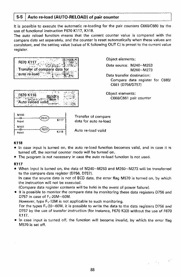
- .. 5-5 Auto re-load (AUTO-RELOAD) of pair counter 1
use of functional instruction F670 K117, K118. The auto reload function means that the current counter value is compared with the
Object elements;
Data source: M240-M253
Data transfer destination: M260- M273
Compare data register for C660/ I C661 (D756ID757)
Object elements: C66OK661 pair counter
Transfer of compare data for auto re-load Input @ K117
K118 Auto re-load valid Input
K118 e In case input is turned on, the auto re-load function becomes valid, and in case it is
C, The piogram is not necessary in case the auto re-load function is not used.
K117 0 When input is turned on, the data of M240-M253 and M260-M273 will be transferred
to the compare data register (D756, 0757). In case the source data is not of BCD data, the error flag M570 is turned on, by which the instruction will not be executed. (Compare data register contents will be held in the event of power failure).
D757 in case of Fl-20M-60M. However, type F,-12M is not applicable to such monitoring. For the types F1-20-60M, it i s possible to write the data to the data registers 0756 and D757 by the use of transfer instruction (for instance, F670 K33) without the use of F670 K117.
0 In case input is turned off, the function will become invalid, by which the error flag M570 is set off.
turned off, the normal counter mode will be turned on.
f
! ?
i e It is possible to monitor the compare data by monitoring these data registers 0756 and
i
88

M273 M260 M253 M240
I, C661 side compare data register C660 side compare data register
(0757) 10756)
In case the current counter value becomes consistent with the compare register value, the setting value (value of K following OUT C660, OUT C661) is transferred to the current value register, and the flag M473 is operated at the same time.
Circuit example-1 Auto reload of pair counter
-i*
X500
OFF while PC is
-Jc _-------- M470 -------- A70 operating a ON while
K500
KO04
K109
49 K117
49 K118
!
Setting of C660X661 to internal counting mode
Setting of C66OK661 to up-count mode
Transfer of 500 to M240-MZ53
Transfer of 004 to M260-M273 (See page-95).
Transfer of 4500 to C66OK661 comparison data register
Auto re-load mode
Counter reset (Output contact C660 is turned off and counter setting value is reset to "0"). Upper 3-digit counter I (programmed first, K=0-999) Lower 3-diait counter } Initial value (programmed later, K=0-999) I M473 is turned on when auto re-load execute (current counter value = 4500).
Resetting of M473 upon elapse of 1 sec. (See page-82).
t
Fig. 5-18 Auto reload circuit example
89

i
When the current value of pair counters C66OK661 reaches 4 "4500". the auto reload output
In this case, the counters C660/
Current value of C66OK661
8 M473 is output. I
0 I
t OFF I
I I C661 are automatically reset, by
C660 contact
r M473 ..+.I
which the current value of counter is preset to initial value ("0" in the
1 sec. 1 sec. case of this example).
NOTE
The auto reload function is used effectively especially when the pair counters C660K661 are used under the high-speed counter mode (M470 = ON) to be described further on, in which the setting value can be preset quickly in the case of coincidence when compared without any influence by the execution cycle.
90

Circuit example-2 ,
Auto reload of high-speed counter e. -
I *-
ON while PC is M70 operating - i t
KO04
K109
1- K116 '- K114 M473
K115
'4571
Count stop
KO00 snput start
M473 -I1
T450
-1--
Setting of C660/C661 to high-counter mode
Setting of C660/C661 to up-count mode
Transfer of 500 to M240-M253
Transfer of 004 to M260-M273 (See page-95).
Transfer of 4500 to C66OK66 register
Auto re-load mode
cpmparison data
Counter reset prohibit by X401 (See page-83.)
X401 rising detection (See page-77.)
M473 is turned on when current counter value is "4500". In this case, X401 rising detection flag M571 is reset. (See page-77).
Holding of M472 (counting start) operation after rising of X401
Initial value I Upper 3-digit setting (K=0--999)
Lower 3-digit setting (K=0--999)
M473 is turned on when current counter value is "4500".
Resetting of M473 (occurrence of auto re-load) upon elapse of 1 sec. (See page-82.)
Fig. 5-19 Auto reload (high-speed counter)
According to the program shown in Fig. 5-19, the counter starts counting operation (input: X400) when the input X401 is turned on. When the value reaches the compare value of 4500, M473 is actuated, by which the output Y430 is operated and is reset upon elapse of one second. In case the sheet rolled out continuously is stamped at the constant interval, the input X400 will appear to be the sheet feed amount detection pulse, while Y430 to be the output for stamp. It is an example of applications.
91
..,...-..-. . . . .
i

I
5-6
i
Direct Output instruction for high-speed counter
The high-speed counters C660/C661 can count the number of ON/OFF of input X400 at high speed (max. 2kHz). These counters can be interruptedheset by the input X401. In addition, it is possible to preset the setting value by the auto reload (function described previously) synchronously with the counting operation. As described previously, the counters can be operated at high speed regardless of execution cycle, however, the repsonse lagging may occur, if the output of compare result to the external unit is depending upon the general cyclic execution. To settle such problem, the designated output is interrupted for direct output, which is the functional instruction to be described further on. With the functional instruction, a maximum of four points direct outputs can be set at the same time. Bear in mind that the maximum counting frequency appears to be 1.5kHz when this instruction is used.
I I- @ K119
Table (1) - K119
ti__?- Table (3)
@ K119
Object elements: Register for table (held in the event of power failure)
Table contents #1 M240-M253 Lower 3-digit BCD
compare data
#2 M260-M273 Upper 3-dight BCD compare data
#3 M254, M255 Table No. (0-3)
c
0 Set the data to M240-M277 in table in advance. e When input is turned on, the above data is transferred and set to table register.
In case M240-M273 are other than BCD data, the error flag M570 is turned on, by which no processing wil l be executed.
a In case input is turned off, no processing will be executed and M570 is turned off.
92

Application example-1 1 Multiple setting of table
#r! M274-M276 Output relay No.
output
_L-__
OFF \ OFF I ON I 431
7 T N 1 OFF’ 1 432 .___ -___
OFF 1 ON I ON 433 -4- I
ON 1 OFF 1 OFF 434
ON 1 OFF ON I 435
OFF 1 436
I I I
---I------
--A
-
ON , ON 1 ON 1 437
#5 M277 output format ON __. Set output OFF ... Reset output
If it is programmed that only one contact of M100-104 is turned on, it is possible to increase the high-speed output table to any quantity as shown at left figure.
In the type F,-20-60, these table are allotted to data register D760-D777, it is possible to monitor the setting data by monitoring these register. Type F,-12M is not applicable to such monitoring.
Table(O1 Tablelll TablelP) Data register
Lower 3-dight compare data
Upper 3-dight compare data
relay No.
format
Output
Output
c- 102.10’.100 data
c- lo5, IOd, lo3 data
.)- Data 430-437 - Data-O=Reset
Data-l=Set outpur
In addition to F670 K119 instruction, it is also possible to set these table by the use of transfer instruction to data resister (for instance, F670 K33).
93

r-
. , . . . . . . . . . . . . . .
i
Object elements: Y430-Y437
ON while PC is 1
~ 7 0 operating
K430 Setting of output prohibit relay No.
@ K120 Prohibit of independent high-speed output Input
0 In case input is turned on, the high-speed output of designated element is prohibited. . The element designating coil F671 is driven all the time by M70.
The IO’ and IO’ digit values of K-No. in F671 are ignored and regarded as 43U. 0-7 will be valid for 0, and 8 is regarded as 0, and 9 as 1 respectively.
0 In case input is turned off, high-speed output is possible for designated element. Where no prohibition is necessary, both F671 and F670 need not to be programmed.
High-speed output
I I simultaneous permit
Object elements: Y430-Y437
High-speed output simultaneous permit Input
0 In case input is turned an, the high-speed output becomes available, which is set at each table. In this case, bear in mind that the output is prohibited for the output in which the independent prohibit instruction is operating.
0 In case input is turned off, al l outputs set at each table (0) - (3) will be prohibited.
Application example-1 2 Simple positioning control
Setting with 3 digits digital switch ( 103,102,1 0’) X500-X513.
Table movement distance
I
High-speed Y430 forward travelling Low-speed forward travelling Y431
Braking output Y432
94

General description of operation (1) The high-speed counters C66OK661 are handled as down counters for detection of
movement amount by the pulse input given from the input X400. (2) The initial setting value of high-speed counter is set by the 3-digit digital switch from
the panel surface. This setting value is total amount movement. (3) When the current value of high-speed counter is decremented and reached "500", the
high-speed forward travelling output Y430 is turned off and the low-speed forward travelling output Y431 is turned on.
(4) When the current value of high-speed counter is further decreased to reach "IOO", the low-speed forward travelling output "431 is turned off and the braking output Y432 is turned on.
(5) The operation is re-started from the high-speed forward travelling process upon elapse of three seconds after the braking output Y432 has been turned on. If the stop input has been entered in this case, the braking output can be maintained.
I
General description of program The overall program is shown on pages 145 and 146. The program is designed in the following procedure;
(1 1 Start/stop sequence (2) Setting of modes for counters C66OK661 (3) Total reset of auxiliary relay applied (41 Preset of counter C661 ( I O 3 digit of total travelling distance) (5) Preset of counter C660 (lo2, IO' digits of total travelling distance) (6) Reset of high-speed output Y430 at table No.0 (Set is executed in item-(IO)). (7) Setting of low-speed output Y431 at table No.1 (8 ) Reset of low-speed output Y431 at table No.2
- - (9) Set of braking output Y432 at table No.3 (10) Reset of braking output Y432 and set of high-speed output Y430
.
95
L
t

. . . ? ’ . .. , . . . . . .. ...* ,
I
PLS M202
M201 Stop holding Y432 Brake Output
I’ OFF while ODeralina
41 M200 Start +I I I - 41 M70 ON while operating
K240
Start
Stop holding
Start reset
C66OK661 down-count
C660/C661 high-speed counter mode
C66OK661 counting start
High-speed output simultaneous permit
XU01 external reset prohibit (See page-83).
M240-M299 simultaneous
(See page-81 1.
C660/C661 counter reset
K103 M71 Initialize pulse
M70 ON while olerating X400 M273 / 1 M263 M260
X510 Input pulse -I Clear Clear
--i-
( l o 3 diait
Digital switch )
X513 --I1
v-j X513 X510
M260-M273 (X510-X513)
- Transfer of C661 current
M260-M263 reset
M273 X M 2 6 0 i lo* i lo’ i d:lr’ On while
M70 operating -It
X500 C I I I
102,10’ digits X507
M260-M273 (X500-.X507)
+ Transfer of C660 current
500-M240-M253 +a, setting
#Q setting
96

M70 Off while operating .* NO programming is necessary. as they have been already reset.
0
Simultaneously reset by
a202 Start pulse iI @ K?19 M70 ON while operating - I t
M202 Start pulse
-I- @ K119
M202 Start pulse -I- I @ KlOO
K109 M70 OFF while operating - M70 ON while operating -I- M70 OFF wh4e operating -
,/% L 4 '
M202 Start pulse - i w @ K119 M70 ON whilc operating -It
M70 OFF while operating - M70 ON while operating
W202 Start pulse -I- @ K119
) Table No.0 #@ setting
Output No.Y430 #@ setting i Y430 output reset #a setting
Table No.0 setting
Reset of high-speed output Y430 when current value i s '500".
Table No.1 R a setting
. - . . , , . . , . .. . . .
as they are output No.Y431 #a setting
Setting of Y431 output 80 setting
Table No.1 setting
"Setting of low-speed o i tpu t Y431 when current value is "500"
10LM240-M253 #@ setting
0 + M260-M273 #@ setting
(See page-951.
setting
i Output reset (Y431) +,s setting
Table No.2 setting
Resetting of low-speed output Y431 when current value is "100"
) Table No.3 S @ setting
not to be set, ) Output No. Y432 W@ Setting
Setting of Y432 output i@ setting
Table No 3 setting
Setting of braking 6u<put'Y432 when current value is"lO0." Braking time
Reset program for braking output Y432
Reset program for braking output Y432
Setting program for high-speed output Y Q O
Fig.5-20 Simple positioning control
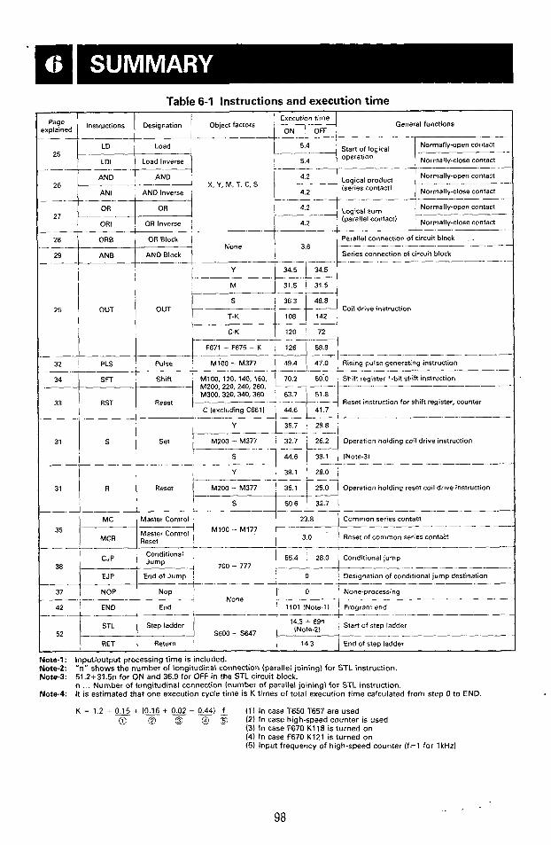
c-4
!
Table 6-1 Instructions and execution time
General functions $:Eed Instwctions I Designation I Object factors '
' AND I AND I Normally-open contact 4.2 I i ANI : AND Inverse i 1 4.2 I
oroduct 26 I L.-.-- X,Y.M,T,C,S
' Normally-open contact
' Normally-close contact - I 4.2
: (parallel contact)
- -. None
. .- - 29
I I Y
-
i
25 OUT OUT
C-K I
.- ._ .._
eset instruction for shift register, counter
32 PLS , Pulse i Mi00 - M377
34 SFT Shift
33
I .- .______. Y
31 Reset
S - - - Master Control Common series contact
Master Control 35 i
3.0 Reset of common series contact M'oo - M177
- ._ .- ___
EndofJump 0
' None-processing - - -. -
1101 INote-1) Program end - 4 - _- None
37
42 ! END I End
52 l4>1Gj 14.3 End of step ladder
.- ___-.-
1 --- ! Start of step ladder 14.3 69n
_i -. - - .- -. __ - . - - 5600- S647
Note-1: Note-2: Note-3:
Note-4:
Inputloutput processing time is included. "n" shows the number of longitudinal connection (parallel joining) for STL instruction. 51.2+31.5n for ON and 36.9 for OFF in the STL circuit block. n ... Number of longitudinal connection (number of parallel joining) for STL instruction. It is estimated that one execution cycle time is K times of total execution time calculated from step 0 to END.
K = 1.2 + 0.15 + (0.16 t 0 2 - 0.44) f (11 In case T650 T657 are used
(3) In case F670 K118 is turned on (4) In case F670 K121 is turned on (5) Input frequency of high-speed counter ( f=l for 1kHz)
(c 12 ,z g~ :s (2) In case high-speed counter is used
I
98
e
8

Table 6-2 Functional instruction and execution time I I I
i
Designations Execution time (psl
. ..... __ Remarks
.... ....... . . .l. ... -__ -T- - - . .- 53,6
Input all-point refresh ...... ............. ... 71
.- i. I
73 I KlOl 1 Input partial-point refresh . . -
n: Setting 1 constant 2137-14.9 ..... - ....... 1.. ._
I ' 53.6 '
K1OZ I Output all-point refresh : 29.2 .- i 4 ........
n: Number
point . . . . . . . . . . . . . . . . . . . . . . . . . . . . . . .
I c Of
223~58.3n ' 53.6 i
I 76 K103 1 All-reset
! .. .... t. - .......
Writing of BCD data for counter . ... ....
79 K105 i Reading of current counter value
8o t K104 ' 53.6 1 ..... .
192 -+ . -+. .- -. - . .- . . . . . I 1 248 \ 53.6
Comparison of zone for current counter
85 I I Comparison of BCD data with current
- -- .... -- - .... ._--! ... ............. .-L .......... I
Comparison of zone for 6-digit counter ~ 365 1 53.6
Transfer of 3-digit decimal constant
.... ........ .......... ..........
- 1 120 I 53.6 -1 60.7
' 60.7
.. ....... ... . ... ...... ........ 1 1;:: I
86 -. .- -. -.~
- .L - ._ - - -.
Kl lO I M473 reset . --
.... - ..... - - ... - . __ .. .. . . .- - - - 70.2 , 75.6
.. ........... .......
............ ..... .. ... ... ...
1 70.2
69.6 75.0
-
I, __ -
- I
15 K114 . Detection of X401 rising
75 -K115
78 K116
K1!7
....... -. .. .- .- .......
....... ... ... ...
.. ..
.e -. _- -. External reset prohibit
- . .___
-. - -
I Transfer of comparison data for autore-load i -'""
92 ! K119 53.6
88
.... .... . - -.
K120 i Independent prohibit of high-speed outpu! 78.0 83.3 I I
. - . . -.
. .- - - .....
i 67.3 , 72.6 1. 94 -I 94 I K121 I Total permit of high-speed output
t
99

c M77
I I permit I ! I
Output inhibit
All output OFF when h177 is turned ON I
Table 6-3 List of special aux. relays (see page 16, 17)
M71 M70
' lOms clock
M76 - ,
Battery i drop voltage I I
ONwhen 1 1 1 ON during RUN banery voltage is dropped
I i ! I
. . - -1
I I
i
I
1 1 I
! i i I
M473 .- - i Shift up;down
(holding of operation ic
i event of power failure1
j set in the case j of shift up/shift
down in C660; i C661. and auto I re-load
1 M472
i Start of counting (high-
1 speed counter!
4-
, ON counting , OFF: Stopping !
1 M471
L'P!DOWN (C660/C661)
. -. _-
T ON: Up i , OFF: Down
i I
M470
High-speed counter t (C660/C661)
!
ON: High-speed I counter ! OFF: Internal I counter I
M575 1 -
Return start of state transfer
_- M574 M573 M571 -1 State transfer I Borrow flag inhibit lholding , of operation in event of power
I failure) i
i ON. Transfer ! I OFF: Transfer inhibit I Detection of
X400. X401 i i I ' rising
M570
Error flag
I
100
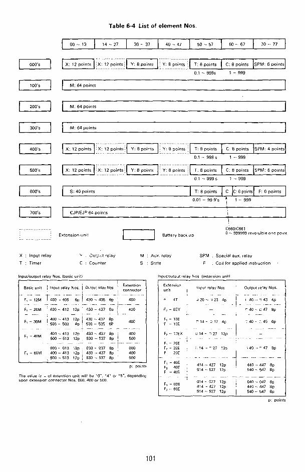
Table 6-4 List of element Nos. r 00 - 13 14 - 27 30 - 37 40 - 47 50 - 57 60 -- 67 30 - 77
0.1 - 999s 1 - 999
M : 64 points I M: 64 points 1
I M: 6 4 ~ o i n t s 1
........................ , ...................... -1 kl2,poin!s ,~ Y: 8 points . Y: 8 points
T: 8 points I C. 8 points ISPM: 4 points1
0.1 - 999 s 1 - 999 ...................
......................
0 1 - 999 s 1 -- 999 I 500's 1
S: 40 points T: 8 points C C: 6 points F: 6 points
0.01 - 99.9's ; 1 - 999 I
CJPiEJP 64 points I 1 \ i
C660!C661 0 - 999999 reversible one polnt 1-1 Battery back UD
.........................
Q- Extension uni:
X : Input relay
T : Timer
'r . I)ut;cr 7e:ay M : Aux. relay SPM : Special aux. relay
C : Counter S : Sta?e F : Coil for applied instruction
Inputioutput relay Nos. (basic unit1 iut'outwt relay Nos. (extension unil l
Basic unit 1 l n x i relay NOS. Extenston Output rdav Nos i Input relay Nos ' unit ... ... .... , .. - _- .... -. . . .
F, - 12M - 1 . i O O - 405 6p ! 430 - 435 6p 400 . . . . . . . . ...... ....... .-
. . . . . . . . . . . . _- .... F - 4T J 20 - i 23 4p
. - 1 . ... .-. I 1 1 do -- 3 43 4p
F7 - 8EY I - 7 40 - i? 47 8p . . . . . . . . . . . .- . . . . . . ~. .
430 - 437 Ep ! 400 ......... 1 ...........
430 - 437 8p 530 - 53s 6~ 400 - - ._ - .... _. ..
430 .. 437 8p 400 530 - 537 8p 500
030 -- 037 8p -&IC. 430 - 437 8p 400 530 - 537 8p ' 500
. . . . -.
F, - 20M ' 400 - 412 12p - . . . . . . . . . . . .
. . . . . . .
F, -- ::EX LI 14 - E 2 7 12p I -
F; - 2CE :. 14 -- 127 !2y i 40 -- z 47 ap
. . . . . . . . . . . . . . . . . . -. . - . -
Fl - 2GE
F - ZOE I . . . . . - .... . -. . .+ .... -
.......... ..
F, -4nM ' 400-413 izp , 500 -513 12p .
000 - 013 12p F, - 60M 400 - 413 12p
, 503 -- 513 12p F' - 4 0 E 414 - 427 12p 440 - 447 Ep
540 - 547 8p F, - - JOE 40i , 514 -. 527 12p p. points
The value in 1 of extension unit will be "0-, "4" or "5'. depending upon extension connector Nos. 000.400 or 500.
. . .~ . . . . . . -. ....... -. .- -- - - ' 014-027 i z P o4n .. 047 8p
A 1 4 - 427 12p ! 440-447 8p 514 - 527 12p I 540 - 547 8p
F, - 60E F; - 60E
p: points
101
. . . . ..*