melsec system q - rs components · 2019. 10. 12. · hmi technical catalogue product catalogue for...
TRANSCRIPT

ProgrammableLogicControllers
MELSECSystem Q
Technical Catalogue
MITSUBISHI ELECTRIC
2004

2 MITSUBISHI ELECTRICMELSEC System Q
The MELSEC System Q
Additional servicesYou will find current information on updates, alterations, new items, and technical support on MITSUBISHI ELECTRIC's web pages(www.mitsubishi-automation.com). The products section of the MITSUBISHI home site includes various documentations of the whole productrange by MITSUBISHI ELECTRIC as well as the current version of this catalogue on hand. All manuals and catalogues can be downloaded.The content is updated daily and to date is provided in German and English.
About this product catalogueDue to the constantly growing product range, technical alteration, and new or changed characteristical features, this catalogue is updatedfrequently.
Texts, figures and diagrams shown in this product catalogue are intended exclusively for explanation and assistance in planning and ordering theprogrammable logic controllers of the MELSEC System Q and the associated accessories. Only the manuals supplied with the units are relevant forinstallation, commissioning and handling of the units and the accessories. The information given in these documentations must be read beforeinstallation and commissioning of the units or software.
Should questions arise with regard to the planning of modules described in this product catalogue, do not hesitate to contact the german branchof the MITSUBISHI ELECTRIC EUROPE B.V. in Ratingen or one of its distributors (see cover page).
© MITSUBISHI ELECTRIC EUROPE B.V. 04/2004 (6th issue)
Technical
Catalogues
New Items2004
FX1S, FX1N, FX2N, FX2NC Series Technical CatalogueProduct catalogue for programmable logic controllers andaccessories for the MELSEC FX family (art. no. 68544)
AnS/QnAS and AnU, QnA(R) Series Technical Catalogues
Product catalogues for programmable logic controllers andaccessories for the MELSEC AnS/QnAS and AnU and QnA(R) series
HMI Technical CatalogueProduct catalogue for operator terminals, visualisation softwareand accessories (art. no. 68542)
Networks Technical Catalogue
Product catalogue for Master and Slave modules as well as acces-sories for the use of programmable logic controllers in open andMELSEC networks (art. no. 136730)
Further Publications within the PLC Range
CPU ModulesTwo new high-performance process modules have been added to theexisting range of PLC CPU modules, the Q12(P)HCPU and Q25(P)HCPU.The new versions of the Q00CPU and Q01CPU CPU modules now alsohave limited multiprocessor capabilities.
I/O ModulesTwo new input modules have been added to the existing range of digitalI/O modules, the QX82 and QX82-S1, each with 64 inputs rated at 24 V.
Special Function ModulesThe new analog module Q64RD-G with 4 galvanically isolated inputchannels enables a temperature measurement with Ni100 resistors.The QJ71C24N and QJ71C24N-R2 RS-232 port modules replace their pre-decessors in the interface module family and provide higher data transferrates. A new RS-422/485 module, the QJ71C24N-R4, has also been addedto the product range.
SoftwareVersion 8.0 of the GX-Developer programming software package hasnow been released. New functions have been added to the IEC-1131programming software package GX IEC Developer, which is nowavailable in version 6.0. With MX4 SCADA a new process visualisationsystem is available, that can handle everything from simple installationsto complex production control systems.

3MITSUBISHI ELECTRIC MELSEC System Q
CONTENTS
MELSEC System Q
SYSTEM DESCRIPTION Introduction of the Q system . . . . . . . . . . . . . . . . . . . . . . . . . . . . . . . . . . . . . . . . . . . . . . . . . . . . . . . . . . . . . . . . . . . . . . . . . . . . . . 4 Configuration and handling . . . . . . . . . . . . . . . . . . . . . . . . . . . . . . . . . . . . . . . . . . . . . . . . . . . . . . . . . . . . . . . . . . . . . . . . . . . . . . . 8 Networks . . . . . . . . . . . . . . . . . . . . . . . . . . . . . . . . . . . . . . . . . . . . . . . . . . . . . . . . . . . . . . . . . . . . . . . . . . . . . . . . . . . . . . . . . . . . . . . . 10
BASIC COMPONENTS Base units . . . . . . . . . . . . . . . . . . . . . . . . . . . . . . . . . . . . . . . . . . . . . . . . . . . . . . . . . . . . . . . . . . . . . . . . . . . . . . . . . . . . . . . . . . . . . . . 12 Power supply modules . . . . . . . . . . . . . . . . . . . . . . . . . . . . . . . . . . . . . . . . . . . . . . . . . . . . . . . . . . . . . . . . . . . . . . . . . . . . . . . . . . . 13 CPU modules . . . . . . . . . . . . . . . . . . . . . . . . . . . . . . . . . . . . . . . . . . . . . . . . . . . . . . . . . . . . . . . . . . . . . . . . . . . . . . . . . . . . . . . . . . . . 14
DIGITAL MODULES Input modules . . . . . . . . . . . . . . . . . . . . . . . . . . . . . . . . . . . . . . . . . . . . . . . . . . . . . . . . . . . . . . . . . . . . . . . . . . . . . . . . . . . . . . . . . . . 18 Output modules . . . . . . . . . . . . . . . . . . . . . . . . . . . . . . . . . . . . . . . . . . . . . . . . . . . . . . . . . . . . . . . . . . . . . . . . . . . . . . . . . . . . . . . . . 20
SPECIAL FUNCTION MODULES Analog modules . . . . . . . . . . . . . . . . . . . . . . . . . . . . . . . . . . . . . . . . . . . . . . . . . . . . . . . . . . . . . . . . . . . . . . . . . . . . . . . . . . . . . . . . . 22 Temperature control modules . . . . . . . . . . . . . . . . . . . . . . . . . . . . . . . . . . . . . . . . . . . . . . . . . . . . . . . . . . . . . . . . . . . . . . . . . . . . 25 Counter modules . . . . . . . . . . . . . . . . . . . . . . . . . . . . . . . . . . . . . . . . . . . . . . . . . . . . . . . . . . . . . . . . . . . . . . . . . . . . . . . . . . . . . . . . 27 Positioning modules . . . . . . . . . . . . . . . . . . . . . . . . . . . . . . . . . . . . . . . . . . . . . . . . . . . . . . . . . . . . . . . . . . . . . . . . . . . . . . . . . . . . . 28 Interface modules . . . . . . . . . . . . . . . . . . . . . . . . . . . . . . . . . . . . . . . . . . . . . . . . . . . . . . . . . . . . . . . . . . . . . . . . . . . . . . . . . . . . . . . 31 Interrupt modules . . . . . . . . . . . . . . . . . . . . . . . . . . . . . . . . . . . . . . . . . . . . . . . . . . . . . . . . . . . . . . . . . . . . . . . . . . . . . . . . . . . . . . . 33
ACCESSORIES Dummy module . . . . . . . . . . . . . . . . . . . . . . . . . . . . . . . . . . . . . . . . . . . . . . . . . . . . . . . . . . . . . . . . . . . . . . . . . . . . . . . . . . . . . . . . . 34 System terminals and connection cables. . . . . . . . . . . . . . . . . . . . . . . . . . . . . . . . . . . . . . . . . . . . . . . . . . . . . . . . . . . . . . . . . . 35 Cables and plugs . . . . . . . . . . . . . . . . . . . . . . . . . . . . . . . . . . . . . . . . . . . . . . . . . . . . . . . . . . . . . . . . . . . . . . . . . . . . . . . . . . . . . . . . 36 Memory cards, adapter units, batteries, connectors . . . . . . . . . . . . . . . . . . . . . . . . . . . . . . . . . . . . . . . . . . . . . . . . . . . . . . . 38 Accessory for Q PC . . . . . . . . . . . . . . . . . . . . . . . . . . . . . . . . . . . . . . . . . . . . . . . . . . . . . . . . . . . . . . . . . . . . . . . . . . . . . . . . . . . . . . . 40
TERMINALS AND DIMENSIONS Terminal assignments. . . . . . . . . . . . . . . . . . . . . . . . . . . . . . . . . . . . . . . . . . . . . . . . . . . . . . . . . . . . . . . . . . . . . . . . . . . . . . . . . . . . 42 Dimensions. . . . . . . . . . . . . . . . . . . . . . . . . . . . . . . . . . . . . . . . . . . . . . . . . . . . . . . . . . . . . . . . . . . . . . . . . . . . . . . . . . . . . . . . . . . . . . 47
PROGRAMMING SYSTEMS
PROGRAMMING MELSOFT software . . . . . . . . . . . . . . . . . . . . . . . . . . . . . . . . . . . . . . . . . . . . . . . . . . . . . . . . . . . . . . . . . . . . . . . . . . . . . . . . . . . . . . . 50 Visualisation software . . . . . . . . . . . . . . . . . . . . . . . . . . . . . . . . . . . . . . . . . . . . . . . . . . . . . . . . . . . . . . . . . . . . . . . . . . . . . . . . . . . . 51 Profibus software . . . . . . . . . . . . . . . . . . . . . . . . . . . . . . . . . . . . . . . . . . . . . . . . . . . . . . . . . . . . . . . . . . . . . . . . . . . . . . . . . . . . . . . . 53
APPENDIX
Order form . . . . . . . . . . . . . . . . . . . . . . . . . . . . . . . . . . . . . . . . . . . . . . . . . . . . . . . . . . . . . . . . . . . . . . . . . . . . . . . . . . . . . . . . . . . . . . 54 Index . . . . . . . . . . . . . . . . . . . . . . . . . . . . . . . . . . . . . . . . . . . . . . . . . . . . . . . . . . . . . . . . . . . . . . . . . . . . . . . . . . . . . . . . . . . . . . . . . . . . 55
NETWORK MODULES Please refer to the Networks Technical Catalogue for the MELSEC System Q network modules.
BASI
CS

4 MITSUBISHI ELECTRICMELSEC System Q
Description
With the MELSEC System Q, MITSUBISHIELECTRIC presents its most powerfull andcompact modular PLC, with multiprocessortechnology for present and future challenges.
The small size, the communicationscapability and the high-performancemultiprocessing are three important char-acteristics of the MELSEC System Q. Itscompactness ensures that it occupies lessspace in the switchgear cabinet and itsdiverse communication facilities guaran-tee flexibility and openness. Dependingon the selected CPU type up to 4096 localand up to 8192 remote I/O points can beaddressed. This controller is particularlysuitable for performing medium- tohigh-performance automation tasks.
The individual systems can be installed indifferent MELSEC and open networks(e.g. MELSECNET, Ethernet or Profi-bus/DP), enabling them to communicatewith one another. The number of I/Os canthus be increased several times.
Thanks to the unique combinationpossibilities of PLC, PC, and motion CPUs aplatform is available that meets everyautomation task.
Special features up to 4096 local I/Os
up to 8192 remote I/Os
interchangeable intelligence
multiprocessor technology with12 different CPU types from3 familys (PLC, PC and motion)
wide range of communications facilities
easy installation
one system platform for all configura-tions
innovative technology for futureapplications
Expandability and performance
As with other Mitsubishi controllers thepower of the MELSEC System Q growswith your application – you simply replaceor add a CPU. When using the multi pro-cessor type CPUs the control and commu-nication tasks are shared by up to fourCPUs. Every system can provide a maxi-mum capacity of 4,096 local I/Os or 8,192remote I/Os.
The integrated memory of up to 252 k pro-gram steps (which conforms to 1 MB RAM)can easily be expanded by up to 32 MB atany time just by slotting in an extensioncard (not for Q00(J) and Q01).
Flash ROM cards are also available for per-manent storage of your controller pro-grams for the Q02 and H type CPUs. Anintegrated buffer battery protects the datain the CPU’s internal RAM against powerfailures.
The MELSEC System Q offers state-of-the-art performance by 1 single processor PLCCPUs, 2 process CPUs, 7 multi processorPLC CPUs as well as 2 diverse motion CPUsand 1 PC CPUs.
PLC CPUs(multi processor type) Q00CPU with 8 k steps program
memory and a program cycle periodof 0.16 µs/logical instruction
Q01CPU with 14 k steps programmemory and a program cycle periodof 0.1 µs/logical instruction
Q02CPU with 28 k steps programmemory and a program cycle period of0.079 µs/logical instruction
Q02HCPU with 28 k steps programmemory and a program cycle period of0.034 µs/logical instruction
Q06HCPU with 60 k steps programmemory, program cycle period of0.034 µs/logical instruction
Q12HCPU with 124 k steps programmemory and a program cycle period of0.034 µs/logical instruction
Q25HCPU with 252 k steps programmemory and a program cycle period of0.034 µs/logical instruction
Process CPUs(multi processor type) Q12PHCPU with 124 k steps program
memory and integrated processfunction
Q25PHCPU with 252 k steps programmemory and integrated process func-tion
PLC CPUs(single processor basic type) Q00JCPU as entry-level model.
Here the CPU (8 k/0.2 µs), base unit andmains adaptor form a compact unit.
Motion CPUs Q172CPUN for positioning applications
with up to 8 axis (per CPU)
Q173CPUN for positioning applicationswith up to 32 axis (per CPU)
PC CPUs PPC-CPU686(MS)-128 personal com-
puter with Celereon processor,128 MB RAM and graphics adapter
The MELSEC System Q
SYSTEM DESCRIPTION
MELSECFX2NC
MITSUBISHI
0 1 2 34 5 6 78 9 10 1112 13 14 15
0 1 2 34 5 6 710 11
IN
OUT
POWER
FX -24MR1N
RUNERROR
100-240VAC
X7 X11 X13 X15X5X3X1S/S X6 X10 X12 X14
X4X2X0NL
24MR-ES/ULY10Y6Y5Y3
COM3 Y4 COM4 Y7 Y11COM2COM1COM024+
Y2Y1Y00V
0 1 2 34 5 6 7
0 1 2 34 5
IN
OUT
POWER
FX -14MR1S
RUNERROR
MITSUBISHI
X7X5X3X1S/S X6X4X2X0NL100-240
VAC
14MR-ES/ULY4Y2Y1Y0
COM0 COM1COM2 Y3 Y524V
0V
A62PEU
QJ71BR11
QJ71BR11
RUN
STATION NO.X10
X1
MODE
MNG
T.PASS D.LINK
SD RD
ERR. L ERR.
0123456789
Q64ADRUN
ERROR
A/D0~±10V0~20mA
CH1
CH2
CH3
CH4
I+
V+
I+
V+
I+
V+
I+
V-
SLD
V-
SLD
V-
SLD
V-
SLD
A.G.
(FG)
V+
1
3
5
7
9
B
D
F
2
4
6
8
A
C
E
12VDC24VDC0.5A
L
L
L
L
L
L
L
L
L
L
L
L
L
L
L
L
COM
QY80
FUSE
0123456789
0 1 2 3 4 5 6 7
8 9 A B C D E F
0123456789
1
3
5
7
9
B
D
F
2
4
6
8
A
C
E
NC
24VDC4mA
COM
QX800 1 2 3 4 5 6 78 9 A B C D E F
0123456789
1
3
5
7
9
B
D
F
2
4
6
8
A
C
E
NC
24VDC4mA
COM
QX800 1 2 3 4 5 6 78 9 A B C D E F
Q06HCPU
RS-232
USB
PULL
MODERUNERR.
USERBAT.
BOOT
Q61P-A2
PULL
MITSUBISHI
POWER
BASE UNITMODEL Q38B
SERIAL 0205020E
POWERRUN
BATTERROR
X0X1X2X3X4X5X6X7X8X9X10X11X12X13X14X15X16X17
X20X21X22X23X24X25X26X27X28X29X30X31X32X33X34X35X36X37
Y0Y1Y2Y3Y4Y5Y6Y7Y8Y9Y10Y11Y12Y13Y14Y15Y16Y17
Y20Y21Y22Y23Y24Y25Y26Y27Y28Y29Y30Y31Y32Y33Y34Y35Y36Y37
RUN
STOP
MITSUBISHIFX -64MT2NC
MELSEC AnU/QnA
MELSEC FX2N
MELSECAnSH/QnAS
MELSEC System Q
MELSECFX1S/FX1N
BASI
CS
The MELSEC PLC Family

5MITSUBISHI ELECTRIC MELSEC System Q
SYSTEM DESCRIPTION
Number of I/Os (x 100) Program memory size (k steps) Program cycle period (ns)
Ove
rvie
wo
fth
eM
ELSE
CSy
stem
QC
PUs
The performance spectrum of the8 different PLC CPUs offers theright solution for all applications.
Combined with the 4 other CPUspossible applications result forvery complex processes as well(see also the following page).
Combinations possibilities
Certain combinations are possible for theselection and use of the CPUs. The combi-nation possibilities can be found in theopposite table and in the graphic at thebottom.
Some of the CPUs can be used as a masteror as a slave CPU, however the master CPUmust always be plugged as the first CPUnext to the mains adaptor to the far left.
Combined with other CPUs the PC CPUmust be positioned to the far right slot.
Depending on the CPUs used the powersupply capacity must be accounted foraccordingly (see also page 13).
SinglePLC CPUs
Multi processorPLC CPUs
Motion CPUs PC CPUs
CPU types Q00JCPU
Q00CPU, Q01CPU,Q02CPU, Q02HCPU,
Q06HCPU, Q12HCPU,Q25HCPU, Q12PHCPU,
Q25PHCPU
Q172CPUQ173CPU PPC-CPU686(MS)-128
Combinations possibilities Stand-alone Up to 4 CPUsin combination
In combination witha PLC master CPU
Stand-alone as master.In combination with a
PLC Master CPU as slave
Max. number of usable CPUsper system 1 only Max. 4 Max. 3 Max. 1
Application (hierarchy) — Master/slave Slave Master/slave
*Q00 and Q01CPU in combination with Motion CPU and PC CPU only!
Selection Criteria
3
2
1
4 MM
M
M
M
M M M
M
M M M
M M
MPLC CPU Motion CPU PC CPU
BASI
CS
0
60
20
80
40
100
120
140
250
Q02CPUQ00JCPU Q00CPU
Q02HCPUQ01CPUQ12HCPU
Q12PHCPU
Q25HCPUQ25PHCPU
Q06HCPU
6 MITSUBISHI ELECTRICMELSEC System Q
Integration of Motion CPU andPersonal Computer CPU
The System Q has the multiple CPU systemfunction which also permits PLC CPUs andMotion CPUs to be loaded together on onebase unit. While data exchange is opti-mized via the back bus of the base unit,space requirements and system costs aresignificantly reduced at the same time.
A Motion CPU can use the SSCNET thatrapidly controls up to 96 axes in a singlesystem and saves wiring. The personalcomputer CPU (Q-PC) enables the accessto I/O modules and intelligent functionmodules and the communication of allCPUs with each other.
The system can be controlled via the PCCPU during stand-alone operation in ahigh-level language such as C++,VB orwith a soft PLC (SX Controller).
QX41QY42
QX41
24VDC4mA
QX41PPC-CPU686 KB/MOUSE PC-CARD
B.RUN
B.RUN
USER
EXITBAT.
RDY
ERR.
B.RST
SERIAL 1
RESET
USB
RGB
UPT
FDIDE
100
LINK/TX
EX.I/F
12
Q173CPU
RS-232
USB
PULL
MODERUNERR.
M.RUNBAT.
BOOT
Q06HCPU
RS-232
USB
PULL
MODERUNERR.
USERBAT.
BOOT
Q06HCPU
RS-232
USB
PULL
MODERUNERR.
USERBAT.
BOOT
Q61P-A2
PULL
MITSUBISHI
POWER
BAMODSERIAL
SE UNITEL Q38B
0205020E
MITSUBISHI MITSUBISHI
SSCNET
ETHERNET
Servoamplifier
Servomotor
Personal computer
Management
Management
1
3
5
7
9
B
D
F
24VDC240VAC2A
L
L
L
L
L
L
L
L
L
L
L
L
L
L
L
L
0123456789
0123456789
1
24VDC4mA
0123456789
B
D
F
24VDC4mA
0123456789
1
3
5
7
9
B
D
F
2
4
NC
24VDC4mA
1
3
5
7
9
B
D
F
2
4
6
8
A
C
E
12VDC24VDC0,5A
L
L
L
L
L
L
L
L
L
L
L
L
L
L
L
L
0123456789
COM
1
3
5
7
9
B
D
F
2
4
6
8
A
C
E
12VDC24VDC0.5A
L
L
L
L
L
L
L
L
L
L
L
L
L
L
L
L
COM
0123456789
0123456789
1
3
5
7
9
B
D
F
2
4
6
8
A
C
E
NC
24VDC4mA
COM
1
3
5
7
9
B
D
F
2
4
6
8
A
C
E
12VDC24VDC0.5A
L
L
L
L
L
L
L
L
L
L
L
L
L
L
L
L
COM
0123456789
1
3
5
7
9
B
D
F
2
4
6
8
A
C
E
12VDC24VDC0.5A
L
L
L
L
L
L
L
L
L
L
L
L
L
L
L
L
COM
0123456789
MITSUBISHI
1
A/D0~±10V0~20mA
CH1
CH2
CH3
CH4
V-
SLD
V-
SLD
V-
SLD
V-
SLD
A.G.
(FG)
1
3
5
7
9
B
D
F
E
12VDC24VDC0.5A
L
L
L
L
L
L
L
L
L
L
L
L
L
L
L
L
MITSUBISHI
12VDC24VDC0.5A
L
L
L
L
L
L
L
L
L
L
L
L
L
L
L
L
1
MITSUBISHI
1
3
5
7
9
B
D
F
2
4
6
8
A
C
E
24VDC240VAC2A
L
L
L
L
L
L
L
L
L
L
L
L
L
L
L
L
0123456789
NC
COM
0123456789
1
3
5
7
9
B
D
F
2
4
6
8
A
C
E
NC
24VDC4mA
COM
0123456789
1
3
5
7
9
B
D
F
2
4
6
8
A
C
E
NC
24VDC4mA
COM
0123456789
1
3
5
7
9
B
D
F
2
4
6
8
A
C
E
NC
24VDC4mA
COM
12VDC24VDC0.5A
L
L
L
L
L
L
L
L
L
L
L
L
L
L
L
L
0123456789
0123456789
1
3
5
7
9
B
D
F
2
4
6
8
A
C
E
NC
24VDC4mA
COM
CON1
1
3
5
7
9
B
D
F
2
4
6
8
A
C
12VDC24VDC0.5A
L
L
L
L
L
L
L
L
L
L
L
L
L
L
L
L
COM
0123456789
MITSUBISHI
BAMODSERIAL
SE UNITEL Q38B
0205020E
MITSUBISHI
MITSUBISHI
POWERHz
PUEXTMON
MODE
SET
REV FWD
STOPRESET
AV
ALARM
REV FWD
DATA PORT
MITSUBISHI
A 500
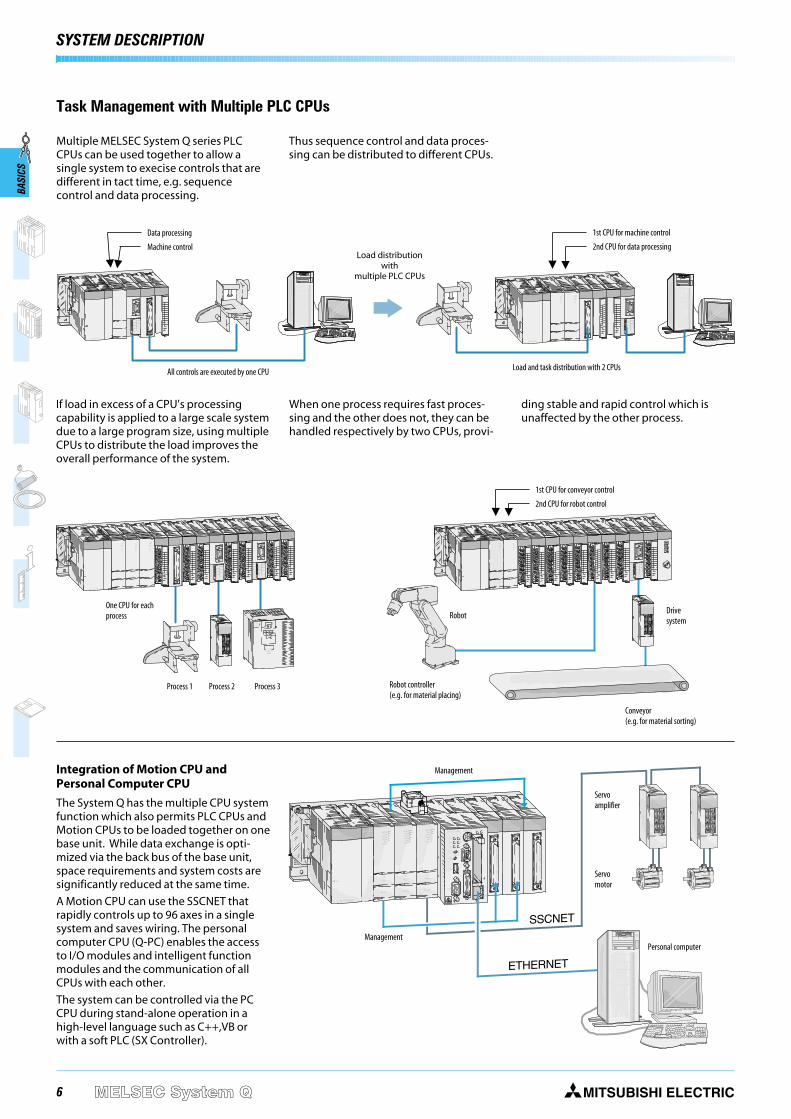
Task Management with Multiple PLC CPUs
Multiple MELSEC System Q series PLCCPUs can be used together to allow asingle system to execise controls that aredifferent in tact time, e.g. sequencecontrol and data processing.
Thus sequence control and data proces-sing can be distributed to different CPUs.
When one process requires fast proces-sing and the other does not, they can behandled respectively by two CPUs, provi-
ding stable and rapid control which isunaffected by the other process.
If load in excess of a CPU's processingcapability is applied to a large scale systemdue to a large program size, using multipleCPUs to distribute the load improves theoverall performance of the system.
Robot Drivesystem
Robot controller(e.g. for material placing)
Conveyor(e.g. for material sorting)
1st CPU for conveyor control
2nd CPU for robot control
Process 1 Process 2 Process 3
Load and task distribution with 2 CPUs
1st CPU for machine control
2nd CPU for data processing
All controls are executed by one CPU
Data processing
Machine controlLoad distribution
withmultiple PLC CPUs
One CPU for eachprocess
SYSTEM DESCRIPTIONBA
SICS

7MITSUBISHI ELECTRIC MELSEC System Q
BASI
CS
DIGITALI/Os
ANALOGINPUTS/
OUTPUTS
PULSECATCH
ANDINTERRUPTMODULES
POSITIONINGMODULES
COMMUNI-CATIONS-MODULES
PLC CPU
PCCPU
MotionCPU
Owing to the modular concept, theMELSEC system Q has a broad range ofuse with many possible applications.
The following modules are available forassembling the system:
To maximize the operational safety, allmodules are isolated from the environ-ment by means of optocouplers.
All I/O modules with screw contacts havetheir own removable terminal blockswhich ensures easy handling duringinstallation. The terminal block can bealternatively exchanged for a spring-loaded terminal block (optional).
Use of digital and special functionmodules
The use of digital and analog modules andmost special function modules is depen-dent only on the maximum addressablenumber of addresses and thus on the CPUused in each case.
Analog input/outputmodulesfor current/voltagesignals and for tempera-ture value acquisition aswell as temperature con-trolling with facility fordirect connection ofPt100 resistance thermo-meters or thermocouples
Digital input/output modulesfor various signal levels withtransistor, relay or triac switches
Positioning modulesHigh-speed counter modules withpossibility for connection of incre-mental shaft encoder or multiaxialpositioning modules for servo andstep drives with up to 8 axis.
Communications modulesInterface modules with RS232/RS422/RS485 interface for connection ofperipherals or for PLC-PLC coupling.
Network modules for Ethernet, Profibus, DeviceNet,AS-I and for setting up MITSUBISHI networks. Mastermodules for use of local analog or digital I/O modules.
Pulse catch and interruptmodulesDigital input modules for pulse storageand for processing subroutines
Network modules
You can find all MELSEC System Q networkmodules and appropriate accessories ofthe MELSEC System Q in the NetworksTechnical Catalogue (art. no. 136730).
You can also find information about otherMitsubishi Electric network products here.
SYSTEM DESCRIPTION
Equipment Features

8 MITSUBISHI ELECTRICMELSEC System Q
MIT
SU
BIS
HI
2M
INS
ER
T
FL
AS
HC
AR
D
BAMODSERIAL 0100017-A
SE UNITEL Q38B
0205020E
POWERCPU I / 00
Q38B(N)
I / 07I / 06I / 05I / 04I / 03
E.S.DI / 02I / 01
QJ71BR11
QJ71BR11
RUN
STATION NO.X10
X1
MODE
MNG
T.PASS D.LINK
SD RD
ERR. L ERR.
0123456789
1
3
5
7
9
B
D
F
2
4
6
8
A
C
E
NC
24VDC4mA
COM
QX800 1 2 3 4 5 6 78 9 A B C D E F
Q06HCPU
RS-232
USB
PULL
MODERUNERR.
USERBAT.
BOOT
EJECT
CARD
MODE
RUN
ERR.
USER
BAT.
BOOT.
ON
STOP RUN
RESET L.CLR
SW1
2
3
4
5
Q61P-A2
PULL
MITSUBISHI
POWER
SYSTEM DESCRIPTION
System structure
The CPU and modules are held in a baseunit which has an internal bus connectionfor communication between the individualmodules and the CPUs. The power supplymodule which supplies the voltage for theentire system is also installed on this baseunit.
The base units are available in 4 differentversions with 3 to 12 module slots. Eachbase unit can be supplemented by meansof an extension unit providing additionalslots.
If you wish to keep open the option of sub-sequent extension of your PLC or if youhave free slots on your base unit, you caninsert dummy modules here. They serve toprotect the free slots from soiling or frommechanical effects but can also be usedfor reserving I/O points.
For cabling larger systems and machines -e.g. in a modular design - the use ofremote I/O modules offers additionalcommunications facilities.
Extension
The base unit and extension units aresimply connected to one another byextension cables. These connecting cablesalso supply the extension units with theoperating voltage of 5 V DC.
Up to seven extension units with up to64 modules can be connected to baseunits or extension base units. The exten-sion may be in the horizontal or verticaldirection and allows a maximum distanceof the extensions cables of 13.2 m.
When choosing the power supply module,the total power consumption of the I/Omodules, of the special function modulesand of the peripherals must be taken intoaccount. If necessary, an extension unitwith a further power supply moduleshould be used.
Configuration
QJ71BR11
QJ71BR11
RUN
STATION NO.X10
X1
MODE
MNG
T.PASS D.LINK
SD RDERR. L ERR.
0123456789
Q64ADRUN
ERROR
A/D0~±10V0~20mA
CH1
CH2
CH3
CH4
I+
V+
I+
V+
I+
V+
I+
V-
SLD
V-
SLD
V-
SLD
V-
SLD
A.G.
(FG)
V+
1
3
5
7
9
B
D
F
2
4
6
8
A
C
E
12VDC24VDC0.5A
L
L
L
L
L
L
L
L
L
L
L
L
L
L
L
L
COM
QY80
FUSE
0123456789
0 1 2 3 4 5 6 7
8 9 A B C D E F
0123456789
1
3
5
7
9
B
D
F
2
4
6
8
A
C
E
NC
24VDC4mA
COM
QX800 1 2 3 4 5 6 78 9 A B C D E F
Q06HCPU
RS-232
USB
PULL
MODERUNERR.
USERBAT.
BOOT
Q06HCPU
RS-232
USB
PULL
MODERUNERR.
USERBAT.
BOOT
Q61P-A2
PULL
MITSUBISHI
POWER
BAMODSERIAL
SE UNITEL Q38B
0205020E
QJ71BR11
QJ71BR11
RUN
STATION NO.X10
X1
MODE
MNG
T.PASS D.LINK
SD RDERR. L ERR.
0123456789
Q64ADRUN
ERROR
A/D0~±10V0~20mA
CH1
CH2
CH3
CH4
I+
V+
I+
V+
I+
V+
I+
V-
SLD
V-
SLD
V-
SLD
V-
SLD
A.G.
(FG)
V+
1
3
5
7
9
B
D
F
2
4
6
8
A
C
E
12VDC24VDC0.5A
L
L
L
L
L
L
L
L
L
L
L
L
L
L
L
L
COM
QY80
FUSE
0123456789
0 1 2 3 4 5 6 7
8 9 A B C D E F
0123456789
1
3
5
7
9
B
D
F
2
4
6
8
A
C
E
NC
24VDC4mA
COM
QX800 1 2 3 4 5 6 78 9 A B C D E F
0123456789
1
3
5
7
9
B
D
F
2
4
6
8
A
C
E
NC
24VDC4mA
COM
QY800 1 2 3 4 5 6 78 9 A B C D E F
0123456789
1
3
5
7
9
B
D
F
2
4
6
8
A
C
E
NC
24VDC4mA
COM
QX800 1 2 3 4 5 6 78 9 A B C D E F
Q61P-A2
PULL
MITSUBISHI
POWER
BAMODSERIAL
SE UNITEL Q38B
0205020E
FUSE
QJ71BR11
QJ71BR11
RUN
STATION NO.X10
X1
MODE
MNG
T.PASS D.LINK
SD RDERR. L ERR.
0123456789
Q64ADRUN
ERROR
A/D0~±10V0~20mA
CH1
CH2
CH3
CH4
I+
V+
I+
V+
I+
V+
I+
V-
SLD
V-
SLD
V-
SLD
V-
SLD
A.G.
(FG)
V+
1
3
5
7
9
B
D
F
2
4
6
8
A
C
E
12VDC24VDC0.5A
L
L
L
L
L
L
L
L
L
L
L
L
L
L
L
L
COM
QY80
FUSE
0123456789
0 1 2 3 4 5 6 7
8 9 A B C D E F
0123456789
1
3
5
7
9
B
D
F
2
4
6
8
A
C
E
NC
24VDC4mA
COM
QX800 1 2 3 4 5 6 78 9 A B C D E F
0123456789
1
3
5
7
9
B
D
F
2
4
6
8
A
C
E
NC
24VDC4mA
COM
QY800 1 2 3 4 5 6 78 9 A B C D E F
0123456789
1
3
5
7
9
B
D
F
2
4
6
8
A
C
E
NC
24VDC4mA
COM
QX800 1 2 3 4 5 6 78 9 A B C D E F
Q61P-A2
PULL
MITSUBISHI
POWER
BAMODSERIAL
SE UNITEL Q38B
0205020E
FUSE
BASI
CS
Main base unit
Extension 1
Extension 2 Extension 7
Memory card
RS232 interface
Base unit
Backup battery(slot on the lower side)
Interface forextension unit(under the transparent cover)
USB interface
Digital I/O module Special function module
Power supplymodule
CPU
Protectivecoverfor removableterminal block

9MITSUBISHI ELECTRIC MELSEC System Q
SYSTEM DESCRIPTION
Mounting the modules
The modules are easily mounted on thebase unit with the aid of a guide lug andan optional fixing screw. Installation canthus be carried out quickly and withoutproblems.
If it becomes necessary to change anI/O module, the screw terminal block canbe removed beforehand. Thus, it is notnecessary to disconnect the entire cabling,but only 2 screws.
Mounting the base unit
The base unit can be mounted by conven-tional screw attachments or with a specialadapter on a DIN rail.
The individual base units can be mountedeither side by side or up to 10 m apart.
QJ71BR11
QJ71BR11
RUN
STATION NO.X10
X1
MODE
MNG
T.PASS D.LINK
SD RD
ERR. L ERR.
0123456789
Q64ADRUN
ERROR
A/D0~±10V0~20mA
CH1
CH2
CH3
CH4
I+
V+
I+
V+
I+
V+
I+
V-
SLD
V-
SLD
V-
SLD
V-
SLD
A.G.
(FG)
V+
1
3
5
7
9
B
D
F
2
4
6
8
A
C
E
12VDC24VDC0.5A
L
L
L
L
L
L
L
L
L
L
L
L
L
L
L
L
COM
QY80
FUSE
0123456789
0 1 2 3 4 5 6 7
8 9 A B C D E F
0123456789
1
3
5
7
9
B
D
F
2
4
6
8
A
C
E
NC
24VDC4mA
COM
QX800 1 2 3 4 5 6 78 9 A B C D E F
0123456789
1
3
5
7
9
B
D
F
2
4
6
8
A
C
E
NC
24VDC4mA
COM
QX800 1 2 3 4 5 6 78 9 A B C D E F
Q06HCPU
RS-232
USB
PULL
MODERUNERR.
USERBAT.
BOOT
Q61P-A2
PULL
MITSUBISHI
POWER
BAMODSERIAL
SE UNITEL Q38B
0205020E
QJ71BR11
QJ71BR11
RUN
STATION NO.X10
X1
MODE
MNG
T.PASS D.LINK
SD RD
ERR. L ERR.
0123456789
Q64ADRUN
ERROR
A/D0~±10V0~20mA
CH1
CH2
CH3
CH4
I+
V+
I+
V+
I+
V+
I+
V-
SLD
V-
SLD
V-
SLD
V-
SLD
A.G.
(FG)
V+
1
3
5
7
9
B
D
F
2
4
6
8
A
C
E
12VDC24VDC0.5A
L
L
L
L
L
L
L
L
L
L
L
L
L
L
L
L
COM
QY80
FUSE
0123456789
0 1 2 3 4 5 6 7
8 9 A B C D E F
0123456789
1
3
5
7
9
B
D
F
2
4
6
8
A
C
E
NC
24VDC4mA
COM
QX800 1 2 3 4 5 6 78 9 A B C D E F
0123456789
1
3
5
7
9
B
D
F
2
4
6
8
A
C
E
NC
24VDC4mA
COM
QX800 1 2 3 4 5 6 78 9 A B C D E F
Q61P-A2
PULL
MITSUBISHI
POWER
BAMODSERIAL
SE UNITEL Q38B
0205020E
Q06HCPU
RS-232
USB
PULL
MODERUNERR.
USERBAT.
BOOT
General specifications
Handling
QJ71BR11
QJ71BR11
RUN
STATION NO.X10
X1
MODE
MNG
T.PASS D.LINK
SD RD
ERR. L ERR.
0123456789
Q64ADRUN
ERROR
A/D0~±10V0~20mA
CH1
CH2
CH3
CH4
I+
V+
I+
V+
I+
V+
I+
V-
SLD
V-
SLD
V-
SLD
V-
SLD
A.G.
(FG)
V+
1
3
5
7
9
B
D
F
2
4
6
8
A
C
E
12VDC24VDC0.5A
L
L
L
L
L
L
L
L
L
L
L
L
L
L
L
L
COM
QY80
FUSE
0123456789
0 1 2 3 4 5 6 7
8 9 A B C D E F
0123456789
1
3
5
7
9
B
D
F
2
4
6
8
A
C
E
NC
24VDC4mA
COM
QX800 1 2 3 4 5 6 78 9 A B C D E F
0123456789
1
3
5
7
9
B
D
F
2
4
6
8
A
C
E
NC
24VDC4mA
COM
QX800 1 2 3 4 5 6 78 9 A B C D E FQ06HCPU
RS-232
USB
PULL
MODERUN
ERR.USER
BAT.BOOT
Q61P-A2
PULL
MITSUBISHI
POWER
BAMODSERIAL
SE UNITEL Q38B
0205020E
BASI
CS
General Specifications Data
Ambient operating temperature 0 – +55 °C
Storage temperature -25 – +75 °C
Ambient relative humidity max. 95 % (non-condensing)
Protection IP 20
Noise durability 1500 Vpp with noise generator; 1 µs at 25 – 60 Hz
Insulation withstand voltage AC 1500 V, 1 min.
Shock resistance 10 G (3 times each in 3 directions) / EN 61131-2
Vibration resistance 2 G: resistant to vibrations from 10 – 55 Hz for 2 hours along all 3 axes; 0.5 G for DIN rail mounting / EN 61131-2
Insulation resistance >5 MΩ (500 V DC)
Ground Class 3
Environment Avoid environments containing corrosive gases, install in a dust-free location.
Certifications UL / CSA / CE / DNV / NK / LR / ABS / GL
Approvals and CE certifications for MELSEC System Q as described on the following pages.

10 MITSUBISHI ELECTRICMELSEC System Q
SYSTEM DESCRIPTIONBA
SICS
MELSEC Networks
TCP/IP ETHERNET
Ready for immediate operation with theworldwide standard TCP/IP protocol. A PCconnected to the Ethernet has full accessto all PLCs in the MELSECNET, all the waydown to the I/Os on the production level.
MELSECNET/10/H and -NET(II)
Low-cost cabling, brilliantly simple set-upand maximum availability thanks toredundancy and Floating Master. Themaximum coverage is up to 30 km.
MELSECNET/B
A cost-effective alternative within the pro-duction level. Enables implementation ofeasily-manageable configurations forcomplex applications by means of distri-buted intelligence.
CC-Link
The network for the control and I/O levelcomprises capabilities like real-timeprocessing and distributed intelligence.Modules of third-party manufacturers canbe integrated.
MELSEC I/O-LINK
Remote module distribution to themachine. Devices of third-party manufac-turers can be integrated. Cabling withtwisted pair cable in a tree structure.
MELSEC FX Peer-to-Peer
The FX-PPN construction enables a net-work for up to 8 FX2N controllers as clients.A standard twisted-pair cable can be usedas the communications media.
TCP/IP ETHERNETTCP/IP ETHERNET
FX1N/FX2N
CC-LINKCC-LINK
CC-LINKCC-LINK
MELSECI/O-LINKMELSECI/O-LINK
MELSECI/O-LINKMELSECI/O-LINK
MELSECFX-PPNMELSECFX-PPN
MELSECNET/10
MELSECNET/BMELSECNET/10
MELSECNET/B
Q
Q
AnSH/QnAS
AnSH/QnAS
AnSH/QnAS
AnU/AnA
MELSECNET/10
MELSECNET(II)MELSECNET/10
MELSECNET(II)
AnSH/QnAS
FX1N/FX2N1
1
Q
1
AnSH/QnAS
7 8
4 5 6
1 2 3
- 0
ABCD EFGH IJKL
MNOP QRST UVWX
YZ!? C1-C4 < > ( )
+ / * = ° % # _ '
9 ACK
PREV
LIST
MAIN
MAC E900
Please refer to the Networks Technical Catalogue for the network modules andaccessories for the MELSEC System Q . There you can find further information forthe wide network product range of Mitsubishi Electric.
COMMAND LEVEL
TCP/IP ETHERNET
CONTROL LEVEL
CC-Link
MELSECNET/10
MELSECNET/H
MELSECNET(II)
MELSECNET/B
PRODUCTION LEVEL
CC-Link
MELSEC I/O-LINK
MELSEC FX-PPN

11MITSUBISHI ELECTRIC MELSEC System Q
SYSTEM DESCRIPTION
BASI
CS
Open Networks
MAP 3.0 ETHERNET
Interdepartmental data exchangebetween the command and productionlevels using a non-proprietary protocolwith short throughput times.
CC-LinkThe new open network for the control andI/O level. Sensors and actuators from differ-ent manufacturers can be connected.Up to 24 stations can be integrated.
Profibus/FMS
Communication between equipmentfrom different manufacturers within asingle plant. Automatic data exchangewith MELSEC networks.
Profibus/DP
Enables quick and simple connection ofsensors and actuators from differentmanufacturers to MELSEC PLCs, with datatransfer rates of up to 12 Mbaud.
DeviceNet
Cost-effective CAN-based network com-munications. Fault-resistant networkstructure where components of differentmanufacturers can be integrated quicklyand easily.
AS-Interface
International standard for the lowest fieldbus level. Connection of conventional sen-sors and actuators with two-core cable.
PRODUCTION LEVEL
Profibus/DP
DeviceNet
AS-Interface
CC-Link
CAN Open
CONTROL LEVEL
Profibus/FMS
CC-Link
COMMAND LEVEL
MAP 3.0 ETHERNET
MAP 3.0 ETHERNETMAP 3.0 ETHERNET
AnU/QnA
FX1N/FX2N
ALPHA
ALPHA
FX1N/FX2N
P R O F I
U SBPROCESS FIELD BUS
PROFIBUS/DPPROFIBUS/DP
M
DeviceNetDeviceNetCANopenCANopen
AS-InterfaceAS-Interface
AnSH/QnAS
AnSH/QnAS
FX1N/FX2N
CC-LINKCC-LINK
CC-LINKCC-LINK
AnSH/QnASQ
1
PROFIBUS/FMSPROFIBUS/FMS
1
1Q
Q
C L P AC L P A
7 8
4 5 6
1 2 3
- 0
ABCD EFGH IJKL
MNOP QRST UVWX
YZ!? C1-C4 < > ( )
+ / * = ° % # _ '
9 ACK
PREV
LIST
MAIN
FX1N/FX2N

12 MITSUBISHI ELECTRICMELSEC System Q
Main base unit
The main base unit is used for holding andcoupling CPUs, power supply unit, inputmodules, output modules and specialfunction modules.
Special features: The modules are automatically
addressed.The automatic addressing can bechanged by means of the function“I/O assignment”.
The units are mounted by means ofscrews or on a profiled rail with an inte-grated adapter.
Main Base Units
BAMODSERIAL 0100017-A
SE UNITEL Q38B
0205020E
Q38B(N)
POWER
I / 07I / 06I / 05I / 04I / 03
E.S.DI / 02I / 01I / 00CPU
BASIC COMPONENTSBA
SICS
The extension base units are connected tothe main base unit by means of assembledbus cables. Thus, a Q system can be ex-panded to max. 7 extension units with upto 64 I/O modules.The extension units provide a slot for theirown power supply module .
Special features: A total of max. 7 extension units can be
connected to a base unit.
The maximum distance from the first tothe last base unit is 13.2 m.
An extension base unit with a power supplymodule must be used in the followingcases: If the power consumption of the
inserted modules exceeds the capacityof the power supply module on thebase unit.
If the voltage drops below 4.75 Vbetween the base unit and the exten-sion unit.
Extension Base Units
Specifications Q52B Q55B Q63B Q65B Q68B Q612B
Slots for power supply modules — — 1 1 1 1
Slots for I/O modules 2 5 3 5 8 12
Installation All extension units provide an installation hole ∅ 5 mm and M4 screws.
Weight kg 0.14 0.23 0.23 0.25 0.35 0.45
Dimensions (W x H x D) mm 106 x 98 x 44.1 189 x 98 x 44.1 189 x 98 x 44.1 245 x 98 x 44.1 328 x 98 x 44.1 439 x 98 x 44.1
Order information Art. no. 140376 140377 136370 129572 129578 129579
Accessories Connection cables (refer to page 36); adapter for DIN rail mounting (refer to page 39)
Specifications Q33B-E Q35B-E Q38B-E Q312B-E
I/O modules 3 5 8 12
Installation All base units provide an installation hole ∅ 5 mm and M4 screws.
Weight kg 0.21 0.25 0.35 0.45
Dimensions (W x H x D) mm 189 x 98 x 44.1 245 x 98 x 44.1 328 x 98 x 44.1 439 x 98 x 44.1
Order information Art. no. 136369 127586 127624 129566
Accessories Connection cables (refer to page 36); adapter for DIN rail mounting (refer to page 39)

13MITSUBISHI ELECTRIC MELSEC System Q
Specifications Q61P-A1 Q61P-A2 Q62P Q63P Q64P
Inputvoltage
(+10%, -15%) V AC 100 – 120 200 – 240 100 – 240 — 100 – 240
(+30%, -35%) V DC — — — 24 —
Input frequency Hz 50 / 60 (±5 %) 50 / 60 (±5 %) 50 / 60 (±5 %) — 50 / 60 (±5 %)
Inrush current 20 A within 8 ms 20 A within 8 ms 20 A within 8 ms 81 A within 1 ms 20 A within 1 ms
Max. input apparent power 105 VA 105 VA 105 VA 45 W 160 VA
Rated outputcurrent
5 V DC A 6 6 3 6 8,5
24 V DC ±10 % A — — 0.6 — —
Overcurrentprotection
5 V DC A ≥ 6.6 ≥ 6.6 ≥ 3.3 ≥ 5.5 ≥ 14.4
24 V DC A — — ≥ 0.66 — —
Overvoltageprotection 5 V DC V 5.5 – 6.5 5.5 – 6.5 5.5 – 6.5 5.5 – 6.5 5.5 – 6.5
Efficiency ≥ 70 % ≥ 70 % ≥ 65 % ≥ 70 % ≥ 70 %
Insulationwithstandvoltage
between primaryand 5 V DC 2830 V AC, 1 min. 2830 V AC, 1 min. 2830 V AC, 1 min. 500 V AC, 1 min. 2830 V AC, 1 min.
between primaryand 24 V DC — — 2830 V AC, 1 min. — —
Max. compensation timeat power failure ms 20 20 20 10 20
Power indicator All modules possess a power LED display.
Terminal screw size All modules possess terminal screw size M 3.5 x 7 mm.
Applicable wire size 0.3 – 2 mm² (AWG 18–14) 0.3 – 2 mm² (AWG 18–14) 0.3 – 2mm² (AWG 18–14) 0.3 – 2 mm² (AWG 16–22) 0.75 – 2 mm² (AWG 11–22)
Weight kg 0.30 0.30 0.39 0.50 0.40
Dimensions (W x H x D) mm 59.2 x 98 x 90 59.2 x 98 x 90 59.2 x 98 x 90 59.2 x 98 x 90 59.2 x 98 x 115
Order information Art.no. 129564 127593 140379 136371 140718
MITSUBISHI
Q61P-A2 POWER
Power supply modules
The power supply modules supply the voltages required foroperation to the the individual modules. The choice is dependenton the power consumption of the individual modules(this is especially important when using multiple CPUs) .
Special features: The readiness for operation is indicated by a red LED.
By use of the power supply Q63P it is possible that controllerscan be supplied by means of additional 24 V DC output.
The power supply modules Q62P and Q64P can be usedworld-wide because they support the wide input range from100 to 240 V AC at 50/60 Hz.
Power Supply Modules
BASIC COMPONENTS
BASI
CS

14 MITSUBISHI ELECTRICMELSEC System Q
BASIC COMPONENTS
Specifications Q00JCPU-E Q00CPU Q01CPU
Type Combination of CPU module (single processor),5 slot base unit and power supply CPU module (single processor) CPU module (single processor)
I/O points 256/2048 1024/2048 1024/2048
CPU self-diagnostic functions CPU error detection, Watch Dog, battery error detection, memory error detection, program check, power supply error detection, fuse error detection
Multi processor operation Not possible With PPC-CPU, Q172CPUN, Q173CPUN only With PPC-CPU, Q172CPUN, Q173CPUN only
Battery buffer All CPU modules are fitted with a lithium-battery with a life expectancy of 5 years.
Memory type ROM RAM, ROM RAM, ROM
Memorycapacity
overall 58 kByte 94 kByte 94 kByte
max. for PLC program 8 k steps (32 kByte) 8 k steps (32 kByte) 14 k steps (56 kByte)
Program cycle period 0.20 µs/log. instruction 0.16 µs/log. instruction 0.10 µs/log. instruction
Timer (T) 512 512 512
Counter (C) 512 512 512
Internal / special relay (M) 8192 8192 8192
Data register / special register (D) 11136 11136 11136
File register (R) — 32768 32768
Interrupt pointer (I) 128 128 128
Pointer (P) 300 300 300
Annunciator (F) 1024 1024 1024
Index register (Z) 10 10 10
Link relay (B) / link register (W) 2048 / 2048 2048 / 2048 2048 / 2048
Number of connectable extensions 2 4 4
Max. number of insertable modules 16 24 24
Internal power consumption (5 V DC) mA 220 250 270
Weight kg 0.66 0.13 0.13
Dimensions (W x H x D) mm 245 x 98 x 98 27.4 x 98 x 89.3 27.4 x 98 x 89.3
Order information Art.no. 140378 138323 138324
Accessories —
Number depends on memory configuration. All specifications refer to the entire unit incl. base unit and power supply unit.
The basic PLC CPUs
The CPU modules of the MELSEC System Q are available as singleand multi processor CPUs through which they achieve a wideapplication range. The performance of the controller here growswith the application by simply replacing the CPU (except Q00J).
While Q00CPU and Q01CPU are classical separate CPUs, theQ00JCPU forms an inseparable unit consisting of CPU, powersupply and base unit and thus enables a low-priced entry intothe modular PLC technology.
The standard CPUs were developed especially for applicationswhere a compact system configuration easily to be realized is tothe fore.
Special features: Every CPU is equipped with an RS232C interface for easy
programming and monitoring from a personal computer oroperating panel.
Integrated Flash ROMs for memory operation withoutadditional memory cards
Processing the inputs and outputs with refresh mode
PLC CPU Modules
Q00CPU
RS-232
PULL
MODERUN
BASI
CS

15MITSUBISHI ELECTRIC MELSEC System Q
High-performance PLC CPUs
With the high-performance CPUs a high processing speed andexpandability are to the fore. They provide a great variety offunctions and an even optimized programming and debuggingenvironment to ensure a flexible response to all systems.
The two process CPU models Q12PHCPU and Q25PHCPU haveextended control functions with two degrees of freedom, PIDcascading and autotuning. These processors also feature a set of52 process instructions and support an unlimited number of PIDloops.
Special features: Every multi processor H-CPU is equipped with an USB interface
for easy programming and monitoring from a personal com-puter.
Processing the inputs and outputs with refresh mode
Floating point arithmetic according to IEEE 754
Special statements for processing PID control loops
Mathematical functions, such as angle/exponential functionsand logarithm
Hot-swap module replacement in RUN mode (with process CPUs)
Multi processor mode is possible with up to 4 CPU modules.
PLC CPU Modules
Q06HCPU
RS-232
USB
PULL
MODERUNERR.
USERBAT.
BOOT
BASI
CS
BASIC COMPONENTS
Specifications Q02CPU Q02HCPU Q06HCPU Q12HCPU Q25HCPU Q12PHCPU Q25PHCPU
Type Multi processor CPU module Process CPU module
I/O points 4096/8192 4096/8192 4096/8192 4096/8192 4096/8192 4096/8192 4096/8192
CPU self-diagnostic functions CPU error detection, Watch Dog, battery error detection, memory error detection, program check, power supply error detection, fuse error detection
Multiprocessor mode Up to 4 CPU modules can be used in combination on one base unit.
Battery buffer All CPU modules are fitted with a lithium-battery with a life expectancy of 5 years.
Memory type RAM, ROM, FLASH RAM, ROM, FLASH RAM, ROM, FLASH RAM, ROM, FLASH RAM, ROM, FLASH RAM, ROM, FLASH RAM, ROM, FLASH
Memorycapacity
overall ≤ 32 MByte ≤ 32 MByte ≤ 32 MByte ≤ 32 MByte ≤ 32 MByte ≤ 32 MByte ≤ 32 MByte
max. forPLC program
28 k steps(112 kByte)
28 k steps(112 kByte)
60 k steps(240 kByte)
124 k steps(496 kByte)
252 k steps(1008 kByte)
124 k steps(496 kByte)
252 k steps(1008 kByte)
Program cycle period 79 ns/log. instruction
34 ns/log. instruction
34 ns/log. instruction
34 ns/log. instruction
34 ns/log. instruction
34 ns/log. instruction
34 ns/log. instruction
Timer (T) 2048 2048 2048 2048 2048 2048 2048
Counter (C) 1024 1024 1024 1024 1024 1024 1024
Internal / special relay (M) 8192 8192 8192 8192 8192 8192 8192
Data register / special register (D) 12288 12288 12288 12288 12288 12288 12288
File register (R) 32768 /max. 1042432
65536 /max. 1042432
65536 /max. 1042432
131072 /max. 1042432
131072 /max. 1042432
131072 /max. 1042432
131072 /max. 1042432
Interrupt pointer (I) 256 256 256 256 256 256 256
Pointer (P) 4096 4096 4096 4096 4096 4096 4096
Annunciator (F) 2048 2048 2048 2048 2048 2048 2048
Index register (Z) 16 16 16 16 16 16 16
Link relay (B) / link register (W) 8192 / 8192 8192 / 8192 8192 / 8192 8192 / 8192 8192 / 8192 8192 / 8192 8192 / 8192
Number of connectable extensions 7 7 7 7 7 7 7
Max. number of insertable modules 64 64 64 64 64 64 64
Internal power consumption (5 V DC) mA 600 640 640 640 640 640 640
Max. compensation timeat power failure ms Varies according to the type of power unit
Weight kg 0.20 0.20 0.20 0.20 0.20 0.20 0.20
Dimensions (W x H x D) mm 27.4 x 98 x 89.3 27.4 x 98 x 89.3 27.4 x 98 x 89.3 27.4 x 98 x 89.3 27.4 x 98 x 89.3 27.4 x 98 x 89.3 27.4 x 98 x 89.3
Order information Art.no. 132561 127585 130216 130217 130218 143529 143530
Accessories Memory cards (refer to page 38) Software PX-Developer
Number depends on memory configuration

16 MITSUBISHI ELECTRICMELSEC System Q
BASI
CS
BASIC COMPONENTS
PC CPU Module
PPC-CPU686 KB/MOUSE PC-CARD
B.RUN
B.RUN
USER
EXITBAT.
RDY
ERR.
B.RST
SERIAL 1
RESET
USB
RGB
UPT
FDIDE
100
LINK/TX
EX.I/F
12
The personal computer for the base unit
The PC CPU module is a compact personal computer of high valuewhich can be installed on the main base unit. Here the Q-PC mas-ters PC typical applications as well as PLC appliations. Therefore, itis suitable as an integrated PC within control systems - e.g. forvisualization, data bases, and log-trace functions of the Microsoftapplication or for programming the System Q in a high-levellanguage. In addition, the system can be controlled as soft PLCaccording to IEC1131 via the optional SX-Controller software.
For the connection to the peripherals I/O and special functionmodules from the MELSEC System Q can be used.
Special features: Employing with low power consumption and high speed Intel
CPU (400 MHz), enabling processing of a large amount of dataat high speed
Windows NT(e) and Windows 2000 OSs are supported
Capable of connecting silicon disk units for use in a placesubject to vibration and shock
Outstanding noise immunity
Fan-less operation and suitable for clean-room applications
Control of a complete system in a high-level language such asC++ or Visual Basic supported
Specifications PPC-CPU 686(MS)-128
Type Personal Computer CPU
CPU Mobile Celereon processor
Processing frequency MHz 400
Memory Mbyte 128 (main) / 2 (cache)
Video Integrated graphics board for a maximum resolution of 1024 x 768 pixles and 65536 colours
Interfaces
serial (RS232C) 2 (1 integrated 9-pin D-SUB connector and 1 optional interface at the extension box which is connnected to "EX I/F")
parallel 1
USB 2 (1 integrated 9-pin D-SUB connector and 1 optional interface at the extension box which is connnected to "EX I/F")
keyboard/mouse 1 x PS/2 connector (keyboard and mouse can be used at the same time with the conversion cable PPC-YCAB-01.)
LAN 1 x ETHERNET interface (100BASE-TX/10BASE-T)
monitor 1 x 15-pin H-DSUB
Connections for drives 1 x disk drive, 2 x hard disk (silicon hard disks are supported)
PC card slots 2 PCMCIA
No. of occupied I/O points 4096/8192
Internal power consumption (5 V DC) mA 3000
Weight kg 0.47
Dimensions (W x H x D) mm 55.2 x 98 x 115
Order informationPPC-SET-200 art. no.: 140108 set with 1 x PC CPU module; 128 MB RAM, no hard disk, driver PPC-DRV-01, without operating systemPPC-SET-21A art. no.: 139815 set with 1 x PC CPU module; 128 MB RAM, 20 GB hard disk, driver PPC-DRV-01, operating system WinNT4.0PPC-SET-21B art. no.: 139816 set with 1 x PC CPU module; 128 MB RAM, 20 GB hard disk, driver PPC-DRV-01, operating system Windows 2000PPC-SET-22C art. no.: 139817 set with 1 x PC CPU module; 128 MB RAM, 320 MB silicon disk, driver PPC-DRV-01, operating system WinNTe4.0
AccessoriesAdditional hard disks, external drives, cables etc. (refer to pages 40 and 41);Soft PLC for the Q PC CPU: SX-Controller for Windows NT/2000 without realtime environment(SX-Controller V0100-1LOC-E, art. no.: 144006)

17MITSUBISHI ELECTRIC MELSEC System Q
Specifications Q172CPUN Q173CPUN
Type Motion CPU Motion CPU
I/O points 8192 8192
No. of control axes 8 32
Interpolation functions Linear interpolation for up to 4 axes, circular interpolation for 2 axes, helical interpolation for 3 axes
Positioning
method PTP (point to point), speed control/speed-position control, fixed pitch feed, constant speed control, position follow-up control,speed switching control, high-speed oscillation control, synchronous control (SV22)
acceleration/deceleration control Automatic trapezoidal acceleration/deceleration, S-curve acceleration/deceleration
compensation Backlash compensation, electronic gear
Programming language Motion SFC, dedicated instructions, software for conveyor assembly (SV13), virtual mechanical support language (SV22)
Processingspeed
SV13 0.88 ms (1. – 8. axis) 0.88 ms (1. – 8. axis), 1.77 ms (9. – 16. axis), 3.55 ms (17. – 32. axis)
SV22 0.88 ms (1. – 4. axis), 1.77 ms (5. – 8. axis) 0.88 ms (1. – 4. axis), 1.77 ms (5. – 12. axis), 3.55 ms (13. – 24. axis),7.11 ms (25. – 32. axis)
Program capacity 14 k steps
No. of positioning points 3200
Programexecution
number of multi executedprograms Max. 256
number of multi active steps Max. 256 steps in all programs
executed tasks
normal Executed in motion main cycle
interruptExecuted in fixed cycles (0.88 ms, 1.7 ms, 3.5 ms, 7.1 ms, 14.2 ms)16 external interrupt points (QI60 interrupt module inputs),executed with interrupt from PLC CPU (when executing the S(P).GINT instruction)
NMI 16 points; executed when input ON is set among an interrupt module (e.g. QI60)
Interfaces USB, RS232C, SSCNET
Real I/O points (PX/PY) 256 (these I/Os can be allocated directly to the motion CPU)
Internal power consumption (5 V DC) A 1.62 1.75
Weight kg 0.25 0.25
Dimensions (W x H x D) mm 27.4 x 98 x 114.3 27.4 x 98 x 114.3
Order information Art. no. 142695 142696
Accessories Manual pulse generator, encoder, interface module (for detailed informations please refer to the technical catalogue "Motion Controller System Q".)
Motion CPU Modules
Q173CPU
RS-232
USB
PULL
MODERUNERR.
M.RUNBAT.
BOOT
CN2
CN1
FRONTSSCNET
The high-speed dynamic motion CPU
The motion controller CPU controls and synchronizes the connec-ted servo amplifiers and servo motors. A motion system besidesthe controller CPU as well includes a PLC CPU. Only after combi-ning a highly dynamic positioning control and a PLC an innova-tive and autarkical motion control system is created.
While the Motion CPU controls large-scale servo movements thePLC CPU is responsible for the machine control and the communi-cation at the same time.
Special features: Using multiple CPUs to distribute the load improves the overall
performance of the whole system
Use of up to 3 motion CPUs within one system
Large scale control system for up to 96 axes per system
Interpolation of 4 axes simultaneously
Software cam control
Virtual and real master axes
Integration in the high-speed SSCNET network for communica-tion with high-performance servo amplifiers at up to 5.6 Mbit/s
BASIC COMPONENTS
BASI
CS

18 MITSUBISHI ELECTRICMELSEC System Q
Digital Input Modules
Detection of process signals
Various input modules are available for converting the digitalprocess signals with different voltage levels into the levels re-quired by the PLC.
Special features: Potential isolation between process and control by means of an
optocoupler is a standard feature.
Indication of input status via LEDs
Modules with 16 connection points have removable terminalblocks with screws.
Assembled cables are available for modules with plugs(Q32CBL: 3 m or 5 m; Q40CBL: 3 m or 5 m).
Different system terminals for module wiring simplification areavailabe (refer to page 35)
Specifications QX10 QX28 QX40 QX40-S1 QX41 QX41-S1
Input points 16 8 16 16 32 32
Insulation method Photocoupler isolation between input terminals and PC power for all modules.
Rated input voltage 100 – 120 V AC(50 / 60 Hz)
100 – 240 V AC(50/60 Hz) 24 V DC 24 V DC 24 V DC 24 V DC
Operating voltage range V 85 – 132 85 – 264 20.4 – 28.8 20.4 – 28.8 20.4 – 28.8 20.4 – 28.8
Max. simultaneously ON
(at rated voltage) 100 % 100 % 100 %(sink type)
100 %(sink type)
100 %(sink type)
100 %(sink type)
Inrush current 200 mA for 1 ms(at 132 V AC)
200 mA for 1 ms(at 132 V AC) — — — —
Rated input current mA 7 (at100VAC,50Hz),8 (at100VAC,60Hz)
7 (at100VAC,50Hz),8 (at100VAC,60Hz),14 (at200VAC,50Hz),17 (at 200 V AC, 60 Hz)
approx. 4 approx. 6 approx. 4 approx. 4
ONvoltage V ≥ AC 80 ≥ AC 80 ≥ DC 19 ≥ DC 19 ≥ DC 19 ≥ DC 19
current mA ≥ AC 5 ≥ AC 5 ≥ DC 3 ≥ DC 4 ≥ DC 3 ≥ DC 4
OFFvoltage V ≤ AC 30 ≤ AC 30 ≤ DC 11 ≤ DC 11 ≤ DC 11 ≤ DC 9.5
current mA ≤ AC 1 ≤ AC 1 ≤ DC 1.7 ≤ DC 1.7 ≤ DC 1.7 ≤ DC 1.5
Load resistance kΩ approx. 18 (50 Hz)approx. 15 (60 Hz)
approx. 15 (50 Hz)approx. 12 (60 Hz) approx. 5.6 approx. 3.9 approx. 5.6 approx. 5.6
Response timeOFF ON ms ≤ 15 (100 V AC, 50/60 Hz) ≤ 15 (100 V AC, 50/60 Hz) 1 – 70 0.05 – 1.2 1 – 70 0.05 – 1.2
ON OFF ms ≤ 20 (100 V AC, 50/60 Hz) ≤ 20 (100 V AC, 50/60 Hz) 1 – 70 0.15 – 1.3 1 – 70 0.15 – 1.3
Common terminal arrangement 16 8 16 16 32 32
Power indicator All modules possess a status LED per input/output.
Connection terminal 18-point removableterminal block
18-point removableterminal block
18-point removableterminal block
18-point removableterminal block 40-pin connector 40-pin connector
No. of occupied I/O points 16 16 16 16 32 32
Applicable wire size mm2 0.3 – 0.75 0.3 – 0.75 0.3 – 0.75 0.3 – 0.75 0.3 0.3
Internal power consumption (5 V DC) mA 50 (all inputpoints ON)
50 (all inputpoints ON)
50 (all inputpoints ON)
60 (all inputpoints ON)
75 (all inputpoints ON)
75 (all inputpoints ON)
Weight kg 0.17 0.20 0.16 0.20 0.15 0.15
Dimensions (W x H x D) mm 27.4 x 98 x 90 27.4 x 98 x 90 27.4 x 98 x 90 27.4 x 98 x 90 27.4 x 98 x 90 27.4 x 98 x 90
Order information Art. no. 129581 136396 132572 136574 132573 146921
Accessories40-pin connector and ready to use connection cables and system terminals (refer to page 35–37);Spring clamp terminal block for exchange against the standard screw terminal block (refer to page 38);IDC terminal block adapter for all 32 point I/O modules with 40-pin connector (refer to page 38)
CPU parameter setting (default setting: 10 ms) at 45 °C Please refer to page 43 for diagrams showing the simultaneously switchable inputs.
1
0
3
5
7
9
B
D
F
2
4
6
8
A
C
E
NC100VDC8mA60Hz7mA50Hz
COM
0123456789ABCDEF
QX100 1 2 3 4 5 6 78 9 A B C D E F
DIGITAL MODULESBA
SICS

MITSUBISHI ELECTRIC MELSEC System Q 19
BASI
CS
Specifications QX42 QX42-S1 QX70 QX71 QX72 QX80 QX81 QX82 QX82-S1
Input points 64 64 16 32 64 16 32 64 64
Insulation method Photocoupler isolation between input terminals and PC power for all modules.
Rated input voltage 24 V DC 24 V DC 5 – 12 V DC 5 – 12 V DC 5 – 12 V DC 24 V DC 24 V DC 24 V DC 24 V DC
Operating voltage range V 20.4 – 28.8 20.4 – 28.8 4.25 – 14.4 4.25 – 14.4 4.25 – 14.4 20.4 – 28.8 20.4 – 28.8 20.4 – 28.8 20.4 – 28.8
Max. simultaneously ON
(at rated voltage)100 %
(sink type)100 %
(sink type) 100 % 100 % 100 % 100 % 100 % 100 % 100 %
Inrush current — — — — — — — — —
Rated input current mA approx. 4 approx. 4approx. 1.2(at 5 V DC)approx. 3.3(at12 V DC)
approx. 1.2(at 5 V DC)approx. 3.3(at 12 V DC)
approx. 1.2(at 5 V DC)approx. 3.3(at 12 V DC)
approx. 4 approx. 4 approx. 4 approx. 4
ONvoltage V ≥ DC 19 ≥ DC 19 ≥ DC 3.5 ≥ DC 3.5 ≥ DC 3.5 ≥ DC 19 ≥ DC 19 ≥ DC 19 ≥ DC 19
current mA ≥ DC 3 ≥ DC 3 ≥ DC 1 ≥ DC 1 ≥ DC 3 ≥ DC 3 ≥ DC 3 ≥ DC 3 ≥ DC 3
OFFvoltage V ≤ DC 11 ≥ DC 9.5 ≥ DC 1 ≤ DC 1 ≤ DC 1 ≤ DC 11 ≤ DC 11 ≤ DC 11 ≤ DC 9,5
current mA ≤ DC 1.7 ≥ DC 1.5 ≥ DC 0.1 ≤ DC 0.1 ≤ DC 0.1 ≤ DC 1.7 ≤ DC 1.7 ≤ DC 1,7 ≤ DC 1,5
Load resistance kΩ approx. 5.6 approx. 5.6 approx. 3.3 approx. 3.3 approx. 3.3 approx. 5.6 approx. 5.6 approx. 5.6 approx. 5.6
Response timeOFF ON ms 1 – 70 0.05 – 1.2 1 – 70 1 – 70 1 – 70 1 – 70 1 – 70 1 – 70 0.1 – 1
ON OFF ms 1 – 70 0.15 – 1.3 1 – 70 1 – 70 1 – 70 1 – 70 1 – 70 1 – 70 0.1 – 1
Common terminal arrangement 32 32 x 2 16 32 32 x 2 16 32 32 x 2 32 x 2
Power indicator All modules with 16 and 32 inputs possess a status LED per input. For modules with 64 inputs the indication is switchable.
Connection terminal 40-pinconnector x 2
40-pinconnector x 2
18-pointremovableterminal block
40-pinconnector
40-pinconnector x 2
18-pointremovableterminal block
Compactconnector37-pin D-Sub
40-pinconnector x 2
40-pinconnector x 2
No. of occupied I/O points 64 64 16 32 64 16 32 64 64
Applicable wire size mm2 0.3 0.3 0.3 – 0.75 0.3 0.3 0.3 – 0.75 0.3 0.3 0.3
Internal power consumption (5 V DC) mA 90 (all inputpoints ON)
90 (all inputpoints ON)
55 (all inputpoints ON)
70 (all inputpoints ON)
85 (all inputpoints ON)
50 (all inputpoints ON)
75 (all inputpoints ON)
90 (all inputpoints ON)
90 (all inputpoints ON)
Weight kg 0.18 0.18 0.14 0.12 0.13 0.16 0.16 0.18 0.18
Dimensions (W x H x D) mm 27.4 x 98 x 90 27.4 x 98 x 90 27.4 x 98 x 90 27.4 x 98 x 90 27.4 x 98 x 90 27.4 x 98 x 90 27.4 x 98 x 90 27.4 x 98 x 90 27.4 x 98 x 90
Order information Art. no. 132574 146922 136397 136398 136399 127587 129594 150836 150837
Accessories40-pin connector and ready to use connection cables and system terminals (refer to page 35–37);Spring clamp terminal block for exchange against the standard screw terminal block (refer to page 38);IDC terminal block adapter for all 32 point I/O modules with 40-pin connector (refer to page 38)
CPU parameter setting (default setting: 10 ms) at 45 °C Please refer to page 43 for diagrams showing the simultaneously switchable inputs.
DIGITAL MODULES
Digital Input Modules
QX41
QX4124VDC4mA
0 1 2 3 4 5 6 7
8 9 A B C D E F
0 1 2 3 4 5 6 7
8 9 A B C D E F
0
1
3
5
7
9
B
D
F
2
4
6
8
A
C
E
NC
24VDC4mA
COM
123456789ABCDEF
QX800 1 2 3 4 5 6 78 9 A B C D E F

20 MITSUBISHI ELECTRICMELSEC System Q
Digital Output Modules
Adapted output technology
The MELSEC System Q output modules have different switchingelements for adaptation to many control tasks.
Special features: Output modules with relay, transistor or triac switches
Potential isolation between process and control by meansof an optocoupler is a standard feature
Modules with potential isolation between the channels
Modules with 16 protection points have removable terminalblocks with screws
Assembled cables are available for modules with D-sub plugs(Q32CBL: 3 m or 5 m; Q40CBL: 3 m or 5 m).
Different system terminals for simplified cabling and to supple-ment the performance of the modules are availabe (refer topage 35).
0
1
3
5
7
9
B
D
F
2
4
6
8
A
C
E
24VDC240VAC2A
123456789ABCDEF
L
L
L
L
L
L
L
L
L
L
L
L
L
L
L
L
QY100 1 2 3 4 5 6 78 9 A B C D E F
NC
COM
Specifications QY10 QY18A QY22 QY40P QY41P QY42P QY50
Outputs 16 8 16 16 32 64 16
Output type Relay Relay Triac Transistor(sink type)
Transistor(sink type)
Transistor(sink type)
Transistor(sink type)
Common terminal arrangement points 16 18 16 16 32 32 16
Insulation method Relay Relay Photocoupler isolation between output terminals and PC power
Rated output voltage 24 V DC / 240 V AC 24 V DC / 240 V AC 100 – 240 V AC 12 / 24 V DC(sink type)
12 / 24 V DC(sink type)
12 / 24 V DC(sink type)
12 / 24 V DC(sink type)
Operating voltage range — — — 10.2 – 28.8 V DC 10.2 – 28.8 V DC 10.2 – 28.8 V DC 10.2 – 28.8 V DC
Min. switching load 5 V DC (1 mA) 5 V DC (1 mA)24 V AC (100 mA)
100 V AC (25 mA)240 V AC (25 mA)
— — — —
Max. switching voltage 125 V DC / 264 V AC 125 V DC / 264 V AC — — — —
Max. output current A 2 2 0.6 0.1 0.1 0.1 0.5
Output current per group TYP A 8 8 4.8 1.6 2 2 4
Inrush current — — — 0.7 for 10 ms 0.7 for 10 ms 0.7 for 10 ms 0.7 for 10 ms
Leakage current at OFF mA ≤ 1.5 mA (120 V AC),≤ 3 mA (240 V AC) ≤0.1 mA ≤ 0.1 mA ≤ 0.1 mA ≤ 0.1 mA
Response timeOFF ON ms ≤ 10 ≤ 10 1 ≤ 1 ≤ 1 ≤ 1 ≤ 1
ON OFF ms ≤ 12 ≤ 12 1 ≤ 1 ≤ 1 ≤ 1 ≤ 1
Lifemechanical Switching 20 million times — — — — —
electrical Switching 100000 times or more — — — — —
Max. switching frequency Switching3600times/h — — — — —
Noise suppression — — RC- Zener diode — — Zener diode
Fuse A — — — — short-circuit proof short-circuit proof 6.7
Power indicator All modules possess a status LED per output.
Fuse blown indicator — — — — — — LED
Connection terminal 18-point removable terminal block 40-pinconnector
40-pinconnector x 2
18-point removableterminal block
No. of occupied I/O points 16 16 16 16 32 64 16
Applicable wire size mm2 0.3 – 0.75 0.3 – 0.75 0.3 – 0.75 0.3 – 0.75 0.3 0.3 0.3 – 0.75
Ext. powersupply req.
voltage — — — 12 – 24 V DC 12 – 24 V DC 12 – 24 V DC 12 – 24 V DC
current mA — — — 10 (24 V DC) 20 (24 V DC) 20 (24 V DC) 20 (24 V DC)
Internal power consumption (5 V DC) mA 430 430 250 65 105 150 80
Weight kg 0.22 0.22 0.40 0.16 0.15 0.17 0.17
Dimensions (W x H x D) mm 27.4 x 98 x 90 27.4 x 98 x 90 27.4 x 98 x 90 27.4 x 98 x 90 27.4 x 98 x 90 27.4 x 98 x 90 27.4 x 98 x 90
Order information Art. no. 129605 136401 136402 132575 132576 132577 132578
Accessories40-pin connector and ready to use connection cables and system terminals (refer to page 35–37);Spring clamp terminal block for exchange against the standard screw terminal block (refer to page 38);IDC terminal block adapter for all 32 point I/O modules with 40-pin connector (refer to page 38)
DIGITAL MODULESBA
SICS

21MITSUBISHI ELECTRIC MELSEC System Q
Specifications QY68A QY70 QY71 QY80 QY81P
Outputs 8 16 32 16 32
Output type Transistor(sink/source type)
Transistor(sink type)
Transistor(sink type)
Transistor(source type)
Transistor(source type)
Common terminal arrangement points All independent 16 32 16 32
Insulation method Photocoupler isolation between output terminals and PC power
Rated output voltage 5 – 24 V DC 5 / 12 V DC (sink type) 5 / 12 V DC (sink type) 12 / 24 V DC (source type) 12 / 24 V DC (source type)
Operating voltage range 4.5 – 28.8 V DC — — 10.2 – 28.8 V DC 10.2 – 28.8 V DC
Min. switching load — — — — —
Max. switching voltage — — — — —
Max. output current A 2 0.016 0.016 0.5 0.1
Output current per group TYP A — 0.256 0.512 4 2
Inrush current 8 A for 10 ms 40 mA for 10 ms 40 mA for 10 ms 4 A for ≤ 10 ms 0.7 A for ≤ 10 ms
Leakage current at OFF mA ≤ 0.1 — — ≤ 0.1 ≤ 0.1
Response timeOFF ON ms ≤ 3 ≤ 0.3 ≤ 0.3 1 1
ON OFF ms ≤ 10 ≤ 0.3 ≤ 0.3 1 1
Lifemechanical — — — — —
electrical — — — — —
Max. switching frequency — — — — —
Noise suppression Zener diode — — Zener diode Zener diode
Fuse A — 1,6 1,6 4 A (2 pices) short-circuit proof
Power indicator All modules possess a status LED per output.
Fuse blown indicator — LED LED LED LED
Connection terminal 18-point removableterminal block
18-point removableterminal block
40-pinconnector
18-point removableterminal block
Compact connector37-pin D-Sub
No. of occupied I/O points 16 16 32 16 32
Applicable wire size mm2 0.3 – 0.75 0.3 – 0.75 0.3 0.3 – 0.75 0.3
Ext. powersupply req.
voltage — 5 / 12 V DC 5 – 12 V DC 12 – 24 V DC 12 – 24 V DC
current mA — 90 (12 V DC) 170 (12 V DC) 20 mA (24 V DC) 40 mA (24 V DC)
Internal power consumption (5 V DC) mA 110 95 150 80 95
Weight kg 0.14 0.14 0.10 0.17 0.15
Dimensions (W x H x D) mm 27.4 x 98 x 90 27.4 x 98 x 90 27.4 x 98 x 90 27.4 x 98 x 90 27.4 x 98 x 90
Order information Art. no. 136403 136404 136405 127588 129607
Accessories40-pin connector and ready to use connection cables and system terminals (refer to page 35–37);Spring clamp terminal block for exchange against the standard screw terminal block (refer to page 38);IDC terminal block adapter for all 32 point I/O modules with 40-pin connector (refer to page 38)
Digital Output Modules
BASI
CS
DIGITAL MODULES
QY41P
QY41P12/24VDC0.1A
0 1 2 3 4 5 6 7
8 9 A B C D E F
0 1 2 3 4 5 6 7
8 9 A B C D E F
0
1
3
5
7
9
B
D
F
2
4
6
8
A
C
E
NC
24VDC4mA
COM
123456789ABCDEF
QX800 1 2 3 4 5 6 78 9 A B C D E F

22 MITSUBISHI ELECTRICMELSEC System Q
Analog Input Modules
321
A/D0~±10V0~20mA
456789101112131415161718
CH1
CH2
CH3
CH4
I+
V+
I+
V+
I+
V+
I+
V-
SLD
V-
SLD
V-
SLD
V-
SLD
A.G.
(FG)
RUN
ERROR
V+
Q64AD
BASI
CS
SPECIAL FUNCTION MODULES
Specifications Q64AD Q68ADV Q68ADI
Input points 4 8 8
Analog input -10 V / +10 V (0 mA / +20 mA) -10 V / +10 V 0 mA / +20 mA
Resolution 16 bits binary (incl. sign) 16 bits binary (incl. sign) 16 bits binary (incl. sign)
Loadresistance
voltage MΩ 1 1 1
current Ω 250 250 250
Max. inputvoltage V ±15 ±15 ±15
current mA ±30 ±30 ±30
I/O characte-ristics
analog input -10 – +10 V 0 – 20 mA -10 – +10 V 0 – 20 mA
digital output 1/4000, 1/12000, 1/16000 1/4000, 1/8000, 1/12000 1/4000, 1/12000, 1/16000 1/4000, 1/8000, 1/12000
Max.resolution
voltage input2.5mV1.25mV0.83mV
—
2.5 mV5 mV1.25 mV1 mV
—
current input —10 µA5 µA3.33 µA
— 0 – 20 mA4 – 20 mA
Overall accuracy ±0.4 % (0 – 55 °C), ±0.1 % (20 – 30 °C) ±0.4 % (0 – 55 °C), ±0.1 % (20 – 30 °C)
Max. conversion time 80 µs/channel (+ 160 µs with temperature drift compensation) 80 µs/channel (+ 160 µs with temperature drift compensation)
Insulation method Photocoupler isolation between output terminalsand PC power for all modules.
Photocoupler isolation between output terminalsand PC power for all modules.
I/O points 16 16 16
Connection terminal All modules are fitted with a terminal block with 18 screw terminals. All modules are fitted with a terminal block with 18 screw terminals.
External power consumption Not neccessary Not neccessary for any module
Applicable wire size mm2 0.3 – 0.75 0.3 – 0.75 0.3 – 0.75
Internal power consumption (5 V DC) mA 630 640 640
Weight kg 0.14 0.19 0.19
Dimensions (W x H x D) mm 27.4 x 98 x 90 27.4 x 98 x 90 27.4 x 98 x 90
Order information Art. no. 129615 129616 129617
±0.4 % (0 – 55 °C), ±0.1 % (20 – 30 °C)
Detection of analog process signals
The analog input modules convert analog process signals, forexample pressure, flow or fill level, linearly into digital values,which are further processed by the Q CPU.
Special features: Up to 8 channels per module (Q68AD) and up to 256 chan-
nels per system (Q CPU)
Resolution of 0.83 mV and 3.33 µA (Q64AD)
Conversion time of 80 µs/channel (Q68AD)
Calculation of average value over the time or measurementcycles can be configured
Potential isolation between process and control by means of anoptocoupler is a standard feature.
All modules are provided with a removable terminal blockfastened with screws.

23MITSUBISHI ELECTRIC MELSEC System Q
Analog Input Modules
Channel isolated and high resolution
The analog input modules Q62AD-DGH and Q64AD-GH convertanalog process signals into digital values with high accuracy. Allchannels are isolated between each other and against the exter-nal power supply with high dielectric withstand voltage for both.
Special features: Potential isolation between each channel and between process
and control is a standard feature.
High resolution: 32 bit signed binary
High accuracy with a reference accuracy of ±0,05 % and atemperature coefficient of ±71,4 ppm/°C
Integrated short circuit protection by limiting the input current
Signal conditioning function for the Q62AD-DGH
A primary delay filter smoothes out the line of digital outputvalues by a user-defined time constant
All modules are provided with a removable terminal blockfastened with screws.
321
A/D-10~10V0~20mA
456789101112131415161718
CH1
CH2
CH3
CH4
I+
V+
I+
V+
I+
V+
I+
V-
SLD
V-
SLD
V-
SLD
V-
SLD
RUN ALM
ERR
V+
Q64AD-GH
Specifications Q62AD-DGH Q64AD-GH
Input points 2 4
Analog input +4 mA / +20 mA -10 V / +10 V (0 mA / +20 mA)
Resolution 16 / 32 bits binary (incl. sign) 16 / 32 bits binary (incl. sign
Loadresistance
voltage MΩ — 1
current Ω 250 250
Max. inputvoltage V ±15 ±15
current mA ±30 ±30
I/O characte-ristics
analog input 4 – 20 mA -10 – +10 V 0 – 20 mA
digital output 0 – 32000 (16 bits)0 – 64000 (32 bits)
-32000 to +32000 (16 bits)-64000 to +64000 (32 bits)
0 – 32000 (16 bits)0 – 64000 (32 bits)
Max.resolution
voltage input —0 to 10 V: 156,3 µV (32 bits), 312.6 µV (16 bits)0 to 5 V: 78.2 µV (32 bits), 156.4 µV (16 bits)1 to 5 V: 62.5 µV (32 bits), 125.0 µV (16 bits)-10 to 10 V: 156.3 µV (32 bits), 312.6 µV (16 bits)
current input 4 to 20 mA: 0.25µA (32 bits), 0.50 µA (16 bits)User defined: 0.151 µA (32 bits), 0.303 µA (16 bits)
0 to 20 mA: 0.312µA (32 bits), 0.625 µA (16 bits)4 to 20 mA: 0.25µA (32 bits), 0.50 µA (16 bits)User defined: 0.151 µA (32 bits), 0.303 µA (16 bits)
Overall accuracy ±0.05 % ±0.05 %
Temperature coefficent ±71.4 ppm/°C (0.00714 %/°C) ±71.4 ppm/°C (0.00714 %/°C)
Max. conversion time 10 ms/2 channels 10 ms/4 channels
Insulation methodTransformer isolation between input channels and between thechannels and PLC power. Photocoupler isolation between I/Oterminals and PLC power
Transformer isolation between input channels.Photocoupler isolation between I/O terminals and PLC power
I/O points 16 16
Connection terminal All modules are fitted with a terminal block with 18 screw terminals. All modules are fitted with a terminal block with 18 screw terminals.
External power consumption 24 V DC, 360 mA Not neccessary
Applicable wire size mm2 0.3 – 0.75 0.3 – 0.75
Internal power consumption (5 V DC) mA 220 890
Weight kg 0.19 0.20
Dimensions (W x H x D) mm 27.4 x 98 x 90 27.4 x 98 x 90
Order information Art. no. 145036 143542
SPECIAL FUNCTION MODULES
BASI
CS

24 MITSUBISHI ELECTRICMELSEC System Q
SPECIAL FUNCTION MODULES
Output of analog control signals
The analog output modules convert digital values predeterminedby the CPU into an analog current or voltage signal. For example,frequency inverters, valves or slide valves are controlled by meansof these signals.
Special features: Up to 8 channels per module (Q64DA) and up to 256 chan-
nels per system
Resolution of 0.333 mV and 0.83 µA
Conversion time of 80 µs / channel
Potential isolation between process and control by meansof an optocoupler is a standard feature. Additional potentialisolation between the channels for the Q62DA-FG.
Disconnection detection function that monitors the outputvalues by means of re-conversion and limit exceeding function(Q62DA-FG only)
The modules are provided with a removable terminal blockfastened with screws.
Analog Output Modules
321
D/A0~±10V0~20mA
456789101112131415161718
CH1
CH2
I+
V+
I+
COM
COM
IN 24VDC
(FG)
RUN
V+
COM
ERROR
Q62DA
BASI
CS
Specifications Q62DA Q62DA-FG Q64DA Q68DAV Q68DAI
Output points 2 2 4 8 8
Digital input-4096 – +4095-12288 –+12287-16384 – +16383
-4096 – +4095-12288 –+12287-16384 – +16383
-4096 – +4095-12288 –+12287-16384 – +16383
-4096 – +4095-12288 –+12287-16384 – +16383
-4096 – +4095-12288 –+12287-16384 – +16383
Analog output -10 V DC – +10 V DC(0 mA – +20 mA DC)
-10 V DC – +10 V DC(0 mA – +20 mA DC)
-10 V DC – +10 V DC(0 mA – +20 mA DC) -10 V DC – +10 V DC 0 mA – +20 mA DC
Loadresistance
voltage output 1 kΩ – 1 MΩ 1 kΩ – 1 MΩ 1 kΩ – 1 MΩ 1 kΩ – 1 MΩ —
current output 0 – 600 Ω 0 – 600 Ω 0 – 600 Ω — 0 – 600 Ω
Max.outputs
voltage V ±12 ±13 ±12 ±12 —
current mA 21 23 21 — 21
Voltage output
I/Ocharacteristics
voltage output 0 – 5 V 0 – 5 V 1 – 5 V 1 – 5 V -10 – +10 V -10 – +10 V user defined user defined
digital input 0 – 4000 0 – 12000 0 – 4000 0 – 12000 -4000 – 4000 -16000 – 16000 -4000 – 4000 -12000 – 12000
Max. resolution 1.25 mV 0.416 mV 1.0 mV 0.333 mV 2.5 mV 0.625 mV 0.75 mV 0.333 mV
Current output
I/Ocharacteristics
current output 0 – 20 mA 0 – 20 mA 4 – 20 mA 4 – 20 mA user defined user defined
digital input 0 – 4000 0 – 12000 0 – 4000 0 – 12000 -4000 – 4000 -12000 – 12000
Max. resolution 5 µA 4 µA 1.66 µA 1.33 µA 1.5 µA 0.83 µA
Overall accuracy ±0.3 % conforms to voltage ±30 mV, current ±60µA (at 0 – 55 °C); ±0.1 % conforms to voltage ±10 mV, current ±20µA (at 20 – 30 °C)
Max. conversion time 80 µs / channel 10 ms / 2 channels 80 µs / channel 80 µs / channel 80 µs / channel
Insulation methodPhotocoupler isolationbetween output terminalsand PLC power
Transformer isolation betweenthe output channels andbetween the channels and PLCpower. Photocoupler isolationbetween output terminalsand PLC power
Photocoupler isolationbetween output terminalsand PLC power
Photocoupler isolationbetween output terminalsand PLC power
Photocoupler isolationbetween output terminalsand PLC power
I/O points 16 16 16 16 16
Connection terminal All modules are fitted with a removable terminal block with 18 screw terminals.
Applicable wire size mm2 0.3 – 0.75
Internal power consumption (5 V DC) mA 330 370 340 390 380
Weight kg 0.19 0.20 0.19 0.18 0.18
Dimensions (W x H x D) mm 27.4 x 98 x 90 27.4 x 98 x 90 27.4 x 98 x 90 27.4 x 98 x 90 27.4 x 98 x 90
Order information Art. no. 127589 145037 127590 138325 138326 Values are valid for all modules except for Q68DAI; Values are valid for all modules except for Q68DAV

25MITSUBISHI ELECTRIC MELSEC System Q
BASI
CS
SPECIAL FUNCTION MODULES
Temperature measurement by thermocouple
These modules are designed to convert external platinum tempe-rature-measuring resistor input values into16 or 32-bit signedbinary temperature measurement values and scaling values.
The reference temperature is determined by means of a Pt100resistance thermometer for the Q64RD module (Q64RD-G additio-nally with Ni100 resistors) and by means of a thermocouple forthe Q64TD and Q64TDV-GH modules.
Special features: Temperature of 4 channels can be measured by one module
Two kinds of platinum temperature measuring resistorscompliant with the JIS, IEC and DIN standards are supported.
The disconnection of a platinum temperature-measuringresistor or cable can be detected on each channel
Selection of sampling processing/time averaging process-ing/count averaging processing
Error compensation by offset/gain value setting
Alarm output when limit value is exceeded
Potential isolation between process and control by meansof an optocoupler is a standard feature. Additional potentialisolation between the channels for Q64TDV-GH and Q64RD-G.
Removable terminal block fastened with screws.
Analog Modules for Temperature Measurement
321
456789101112131415161718
Q64RD
CH1
CH2
CH3
CH4
a1
a2
a3
a3
B1
B2
B3
B3
A1
A2
A3
A3
b1
b2
b3
b3
SLD
(FG)
Q64RDRUN
ERR.
Specifications Q64RD Q64RD-G Q64TD Q64TDV-GH
Input channels 4 4 4 4
Connectable thermocouple typePt100 (conforms to JIS C 1604-1989 andDIN IEC 751),JPt100 (conforms to JIS C 1604-1981)
Pt100 (conforms to JIS C 1604-1997and DIN IEC 751-1983),JPt100 (conforms to JIS C 1604-1981),Ni100Ω (conf. to DIN 43760-1987)
K, E, J, T, B, R, S, N(conforms to JIS C1602-1995,IEC 584-1 and 584-2)
K, E, J, T, B, R, S, N(conforms to JIS C1602-1995,IEC 584-1 and 584-2)
Temperature measuring range Pt100: -200 – 850 °C,JPt 100: -180 – 600 °C
Pt100: -200 – 850 °C,JPt 100: -180 – 600 °C,Ni100Ω: -60 – 180 °C
Depends on the thermocouple used Depends on the thermocouple used
Temperature scaling value16-bit, signed binary:-2.000 – +8.50032-bit, signed binary:-200.000 – +850.000
16-bit, signed binary:-2.000 – +8.50032-bit, signed binary:-200.000 – +850.000
16-bit, signed binary:-2.700 – +18.20032-bit, signed binary: —
16-bit, signed binary:-25.000 – +25.00032-bit, signed binary: —
Max. resolution °C 0.025 0.025 °C B, R, S, N: 0.3 °C; K, E, J, T: 0.1 °C B: 0.7 °C; R, S: 0.8 °C, K, T: 0.3 °C; ET: 0.2 °C;J: 0.1 °C; N: 0.4 °C; Voltage: 4 µV
Cold junction temp. compensation accuracy — — ±1.0 °C ±1.0 °C
Overall accuracy±0.08 % (accuracy relative tofull-scale value)at ambient temperature 25 ± 5 °C
±0,04 % (accuracy relative tofull-scale value)at ambient temperature 25 ± 5 °C
Depends on the thermocouple used Depends on the thermocouple used
Max. conversion time 40 ms / channel 40 ms per channel 20 ms / channel 20 ms / channel
Analog inputs 4 channels/module 4 channels/module 4 channels/module+ Pt100 connection
4 channels/module+ Pt100 connection
Temp. measurement output current mA 1 1 — —
Insulation method Transformer insulation betweenpower supply and temperature inputs
Photocoupler isolation between eachchannel and PLC power.Transformer isolation betweenmeasuring input and channel
Transformator insulation betweenthermocouple inputs as well asthermocouple and earth
Transformer isolation between eachchannel and between the channels andPLC power
Disconnection detection For each channel independent For each channel independent For each channel independent For each channel independent
I/O points 16 16 16 16
Connection terminal All modules are fitted with a removable terminal block with 18 screw terminals.
Applicable wire size mm2 0.3 – 0.75 0.3 – 0.75 0.3 – 0.75 0.3 – 0.75
Internal power consumption (5 V DC) mA 600 620 500 500
Weight kg 0.17 0.20 0.25 0.25
Dimensions (W x H x D) mm 27.4 x 98 x 90 27.4 x 98 x 112 27.4 x 98 x 90 27.4 x 98 x 90
Order information Art. no. 137592 154749 137591 143544

26 MITSUBISHI ELECTRICMELSEC System Q
SPECIAL FUNCTION MODULESBA
SICS
Temperature control modules with PID algorithm
These modules enable PID algorithm temperature controlwithout placing any load on the PLC CPU for the temperaturecontrol tasks.
Special features: Four temperature input channels
Auto-tuning function for the 4 PID control circuits
Temperature control can continue even when the PLC programis stopped
Transistor output with pulse train to drive the actuator in thecontrol circuit
The module is provided with a removable terminal blockfastened with screws.
Temperature Control Modules
A1
B1
B2
b1
b2
NC+ -
A2
L1
L2
L3
L4
A3
B3
B4
b3
b4
A4
RUN ALM
ERR
Q64TCRT
321
456789101112131415161718
Specifications Q64TCRT Q64TCRTBW Q64TCTT Q64TCTTBW
Control output type Transistor Transistor Transistor Transistor
Inputs 4 channels per module 4 channels per module / broken wiredetection 4 channels per module 4 channels per module / broken wire
detection
Supported thermocouples Pt100 (-200 – +600 °C), JPt100 (-200 – +500 °C) R, K, J, T, S, B, E, N, U, L, P L II, W5Re/W26Re
Sampling cycle 0.5 s / 4 channels 0.5 s / 4 channels 0.5 s / 4 channels 0.5 s / 4 channels
Control output cycle s 1 – 100 1 – 100 1 – 100 1 – 100
Input filter 1 – 100 s (0 s: input filter OFF) 1 – 100 s (0 s: input filter OFF) 1 – 100 s (0 s: input filter OFF) 1 – 100 s (0 s: input filter OFF)
Temperature control method PID ON/OFF impulse or 2-position control PID ON/OFF impulse or 2-position control
PID constantrange
PID constant setting Setting with automatic tuning possible Setting with automatic tuning possible
proportional band P 0.0 – 1000 % (0 %: 2-position control) 0.0 – 1000 % (0 %: 2-position control)
integral constant I 1 – 3600 s 1 – 3600 s 1 – 3600 s 1 – 3600 s
differential constant D 1 – 3600 s (0 setting for PID control) 1 – 3600 s (0 setting for PID control) 1 – 3600 s (0 setting for PID control) 1 – 3600 s (0 setting for PID control)
Target value setting range Within the temperature range of the Pt100 sensor used Within the temperature range of the thermocouple used
Dead band setting range 0.1 – 10.0 % 0.1 – 10.0 % 0.1 – 10.0 % 0.1 – 10.0 %
Transistoroutput
output signal (sink) ON/OFF pulse ON/OFF pulse ON/OFF pulse ON/OFF pulse
rated load voltage 10 – 30 V DC 10 – 30 V DC 10.2 – 30 V DC 10.2 – 30 V DC
max. load current 0.1 A/1 point, 0.4 A/common 0.1 A/1 point, 0.4 A/common 0.1 A/1 point, 0.4 A/common 0.1 A/1 point, 0.4 A/common
max. rush current 400 mA for 10 ms 400 mA for 10 ms 400 mA for 10 ms 400 mA for 10 ms
max. voltage dropwhen ON
0.1 V DC (TYP) 0.1 A2.5 V DC (MAX) 0.1 A
0.1 V DC (TYP) 0.1 A2.5 V DC (MAX) 0.1 A
0.1 V DC (TYP) 0.1 A2.5 V DC (MAX) 0.1 A
0.1 V DC (TYP) 0.1 A2.5 V DC (MAX) 0.1 A
response time OFF → ON: < 2 msON → OFF: < 2 ms
OFF → ON: < 2 msON → OFF: < 2 ms
OFF → ON: < 2 msON → OFF: < 2 ms
OFF → ON: < 2 msON → OFF: < 2 ms
Insulation method Transformer Transformer Transformer Transformer
I/O points 16 / 1 slot 32 / 2 slots 16 / 1 slot 32 / 2 slots
Connection terminals All modules are fitted with a terminal block with 18 screw terminals.
Applicable wire size mm2 0.3 – 0.75 0.3 – 0.75 0.3 – 0.75 0.3 – 0.75
Internal power consumption (5 V DC) mA 550 60 550 640
Weight kg 0.2 0.3 0.2 0.3
Dimensions (W x H x D) mm 27.4 x 98 x 90 27.4 x 98 x 90 27.4 x 98 x 90 27.4 x 98 x 90
Order information Art. no. 136386 136387 136388 136389

27MITSUBISHI ELECTRIC MELSEC System Q
SPECIAL FUNCTION MODULES
BASI
CS
High-speed counter with automatic detection of rotationdirection
These counter modules detect signals with a frequency whichcannot be detected by normal input modules. For example,simple positioning tasks or frequency measurements can berealized.
Special features: Input for incremental shaft encoder with automatic forward
and reverse detection
Preset count via external signals or the PLC program with theaid of the PRESET function
Ring counter function for counting up to a predefined valuewith automatic resetting to the starting value
Functions such as speed measurement, definition of switchingpoints or periodic counting are available.
The modules QD62 are provided with a 40-pin connectorinterface (for suitable connectors, please refer to the chapter"Accessories").
The module QD60P8-G is provided with a removable terminalblock fastened with screws.
High-Speed Counter Modules
QD62EØ AØ B
DEC.FUNC. FUSE
CH1 CH2
Specifications QD62E QD62 QD62D QD60P8-G
Counter inputs 2 2 2 8
Signal levels 5 / 12 / 24 V DC ( 2 – 5 mA) 5 / 12 / 24 V DC (2 – 5 mA) 5 / 12 / 24 V DC ( 2 – 5 mA) (RS422A) 5 / 12 / 24 V DC
Max. counting frequency kHz 200 200 500 (differential) 30
Max. countingspeed
1-phase-input kHz 200 or 100 200 or 100 500 or 200 30
2-phase-input kHz 200 or 100 200 or 100 500 or 200 —
Counting range 32 bits + sign (binary),-2147483648 – +2147483647
32 bits + sign (binary),-2147483648 – +2147483647
32 bits + sign (binary),-2147483648 – +2147483647
16 bits binary: 0 – 3276732 bit binary: 0 – 9999999932 bit binary: 0 – 2147483647
Counter type All modules are equipped with UP/DOWN preset counter and ring counter function. Moving average function,alarm output and pre-scale function
Comparison range 32 bits + sign (binary) 32 bits + sign (binary) 32 bits + sign (binary) 32 bits + sign (binary)
External digital input points Preset, function start Preset, function start Preset, function start Preset, function start
Rated voltage/current for external input 5 / 12 / 24 V DC (2 – 5 mA) 5 / 12 / 24 V DC (2 – 5 mA) 5 / 12 / 24 V DC (2 – 5 mA) (RS422A) 5 / 12 / 24 V DC
External digital output points(coincidence signal)
2 points/channel 12 / 24 V DC0.1 A/point, 0.4 A/common (source)
2 points/channel 12 / 24 V DC0.5 A/point, 2.0 A/common (sink)
2 points/channel 12 / 24 V DC0.5 A/point, 2.0 A/common (sink) —
I/O points 16 16 16 32
Connection terminal 40-pin connector interfaceon the front
40-pin connector interfaceon the front
40-pin connector interfaceon the front
Terminal block with18 screw terminals
Applicable wire size mm2 0.3 0.3 0.3 0.3 – 0.75
Internal power consumption (5 V DC) mA 330 300 380 580
Weight kg 0.12 0.11 0.12 0.17
Dimensions (W x H x D) mm 27.4 x 98 x 90 27.4 x 98 x 90 27.4 x 98 x 90 27.4 x 98 x 90
Order information Art. no. 128949 132579 132580 145038
Accessories 40-pin connector and ready to use connection cables and system terminals (refer to page 35–37)

28 MITSUBISHI ELECTRICMELSEC System Q
BASI
CS
SPECIAL FUNCTION MODULES
Positioning Modules
QD70P4RUN AX1
AX2AX3AX4ERR.
CON1
QD70P4RUN AX1
AX2AX3AX4ERR.
CON1
Multi-axis positioning
The modules are especially designed for systems including mul-tiple axes that do not require any extensive control. The QD70P4controls up to 4 axes and the QD70P8 up to 8 axes. Since any num-ber of positioning modules can be used the number of axes to becontrolled as well is unlimited.
Special features: Control of 4 or 8 axes by one module and more than 8 axes by
using multiple modules
Quick start of up to 8 axes simultaneously (0.1 ms per axis afterstart command from the CPU)
Various positioning control systems are selectable.
Easy parametrizing and positional data setup via optionallyavailable positioning software GX Configurator-PT
Specifications QD70P4 QD70P8
Number of control axes 4 8
Interpolation —
Points per axis 10 (by PLC program or with the positioning software GX Configurator PT)
Output signal Pulse chain
Output frequency kHz 1 – 200 000
Positioning method PTP positioning; speed/locus positioning; path control
Positioning
unitsAbsolute data: -2 147 483 648 – 2 147 483 647 pulseIncremental method: -2 147 483 648 – 2 147 483 647 pulseSpeed/position switching control: 0 – 2 147 483 647 pulse
speed 0 – 200 000 pulse/s
acceleration/decelerationprocessing Automatic, acceleration and deceleration step by step
acceleration anddeceleration time 0 – 32767 ms
Pulse output type Open collector output
Max. servo motor cable length m 2 2
I/O points 32 32
Applicable wire size 0.3 mm2 (with connector A6CON1); AWG24 (with connector A6CON2)
Internal power consumption (5 V DC) mA 550 740
External power consumption (24 V DC) mA 65 120
Weight kg 0.15 0.17
Dimensions (W x H x D) mm 27.4 x 98 x 90 27.4 x 98 x 90
Order information Art.no. 138328 138329
Accessories 40-pin connector and ready to use connection cables and system terminals (refer to page 35–37)

29MITSUBISHI ELECTRIC MELSEC System Q
BASI
CS
SPECIAL FUNCTION MODULES
Positioning with an open control loop
The modules generate the travel command via a pulse chain.The speed is proportional to the pulse frequency and the distancetravelled is proportional to the pulse length.
Special features: Control of up to three axes with linear interpolation (QD75P4)
or circular interpolation (QD75P2, QD75P4)
Storage of up to 600 positional data in the flash ROM (noback-up battery necessary)
Units of travel can be defined in pulses, mm, inches or degrees.
Configuration and presetting of all 600 positional data is per-formed via the PLC program or with the aid of the program-ming software GX Configurator QP. This software runs underWindows 95/98 and Windows 2000/NT.
Positioning Modules
QD75P2RUN AX1
AX2
ERR.
AX1AX2
Specifications QD75P1 QD75P2 QD75P4Number of control axes 1 2 4
Interpolation — 2 axis linear and circular interpolation 2, 3, or 4 axis linear and2 axis circular interpolation
Points per axis 600 pieces of data with PLC program, 100 pieces of data with GX Configurator QPOutput type Open collector Open collector Open collectorOutput signal Pulse chain Pulse chain Pulse chainOutput frequency kHz 1 – 200 1–200 1–200
Positioning
method PTP control: absolute data and/or incremental; speed/position swiching control: incremental;locus/speed control: incremental; path control: absolute data and/or incremental
units
Absolute data: -2 147 483 648 – 2 147 483 647 pulse-21 4748 364,8 – 214 748 364.7 µm-21 474.83648 – 21 474.83647 inch
0 – 359.99999 degree
Incremental method: -2 147 483 648 – 2 147 483 647 pulse-214 748 364,8 – 214 748 364,7 µm-21 474.83648 – 21 474.83647 inch-21 474.83648 – 21 474.83647 degree
Speed/position switching control:0 – 2 147 483 647 pulse0 – 21 4748 364.7 µm0 – 21 474.83647 inch0 – 21 474.83647 degree
speed
1 – 1 000 000 pulse/s0.01 – 20 000 000.00 mm/min0.001 – 200 000.000 degree/min0.001 – 200 000.000 inch/min
acceleration/decelerationprocessing Automatic trapezoidal or S-pattern acceleration and deceleration or automatic S-pattern acceleration and deceleration
acceleration anddeceleration time
1 – 8388608 ms(4 patterns each can be set)
rapid stop decceleration time 1 – 8388608 msMax. length for servo motor cable m 2 2 2I/O points 32 32 32Internal power consumption (5 V DC) mA 400 460 580Weight kg 0.15 0.15 0.16Dimensions (W x H x D) mm 27.4 x 98 x 90 27.4 x 98 x 90 27.4 x 98 x 90
Order information Art.no. 132581 132582 132583
Accessories 40-pin connector and ready to use connection cables and system terminals (refer to page 35–37);Programming software: GX Configurator QP, art. no.: 132219

30 MITSUBISHI ELECTRICMELSEC System Q
BASI
CS
SPECIAL FUNCTION MODULES
QD75P2RUN AX1
AX2
ERR.
AX1AX2
Specifications QD75D1 QD75M1 QD75D2 QD75M2 QD75D4 QD75M4Number of control axes 1 1 2 2 4 4
Interpolation — — 2 axis linear and circular interpolation 2, 3, or 4 axis linear and2 axis circular interpolation
Points per axis 600 pieces of data with PLC program, 100 pieces of data with GX Configurator QPOutput type Differential driver SSCNET Differential driver SSCNET Differential driver SSCNETOutput signal Pulse chain BUS Pulse chain BUS Pulse chain BUSOutput frequency kHz 1 –1000 1 –1000 1 –1000 1 –1000 1 –1000 1 –1000
Positioning
method PTP control: absolute data and/or incremental; speed/position swiching control: incremental;locus/speed control: incremental; path control: absolute data and/or incremental
units
Absolute data: -2 147 483 648 – 2 147 483 647 pulse-21 4748 364.8 – 214 748 364.7 µm-21 474.83648 – 21 474.83647 inch
0 – 359.99999 degree
Incremental method: -2 147 483 648 – 2 147 483 647 pulse-214 748 364.8 – 214 748 364,7 µm-21 474.83648 – 21 474.83647 inch-21 474.83648 – 21 474.83647 degree
Speed/positionswitching control: 0 – 2 147 483 647 pulse
0 – 21 4748 364.7 µm0 – 21 474.83647 inch0 – 21 474.83647 degree
speed
1 – 1 000 000 pulse/s0.01 – 20 000 000.00 mm/min0.001 – 200 000.000 degree/min0.001 – 200 000.000 inch/min
acceleration/decelerationprocessing Automatic trapezoidal or S-pattern acceleration and deceleration or automatic S-pattern acceleration and deceleration
acceleration anddeceleration time
1 – 8388608 ms(4 patterns, each can be set)
rapid stop decceleration time 1 – 8388608 msMax. length for servo motor cable m 10 30 10 30 10 30I/O points 32 32 32 32 32 32Internal power consumption (5 V DC) mA 520 520 560 560 820 820Weight kg 0.15 0.15 0.15 0.15 0.16 0.16Dimensions (W x H x D) mm 27.4 x 98 x 90 27.4 x 98 x 90 27.4 x 98 x 90 27.4 x 98 x 90 27.4 x 98 x 90 27.4 x 98 x 90
Order information Art.no. 129675 142153 129676 142154 129677 142155
Accessories 40-pin connector and ready to use connection cables and system terminals (refer to page 35–37);Programming software: GX Configurator QP, art. no.: 132219
Long distance positioning
The modules QD75D1, QD75D2, and QD75D4 are suitable forbridging long distances between module and drive system.The modules provide differential outputs that allow largemotor cable lengths.
QD75D1, QD75D2, and QD75D4 are designed for the operationacross the motion network SSCNET.
Special features: Control of up to four axes with linear interpolation
(QD75D4/QD75M4) or two axes circular interpolation(QD75D2/QD75M2, QD75D4/QD75M4)
Storage of up to 600 positional data in the flash ROM(no back-up battery necessary)
Units of travel can be defined in pulses, mm, inches or degrees.
Configuration and presetting of all 600 positional data is per-formed via the PLC program or with the aid of the program-ming software GX Configurator QP. This software runs underWindows 95/98 and Windows 2000/NT.
Positioning Modules

31MITSUBISHI ELECTRIC MELSEC System Q
BASI
CS
SPECIAL FUNCTION MODULES
Data exchange with peripheral devices
This module enables communication with peripheral devicesvia a standard RS232 interface. The peripherals are connectedpoint-to-point on a 1:1 basis.
Special features: The QJ71C24N provides one RS232 and one RS422/485 inter-
face. The QJ71C24-R2 provides two RS232 interfaces and theQJ71C24N-R4 two RS422/485 interfaces.
Enables PCs connected to the system to access the full data setof the MELSEC Q CPU using graphic process supervision ormonitoring software
Support for plain ASCII data exchange with connected devicessuch as barcode readers, scales and identification systems
Integrated flash ROM memory for logging quality, productivityor alarm data that can be printed out when required
Module and communications status shown by LEDs
Communications test and monitor function are possible withthe software GX-Configurator UT
Interface Modules
QJ71C24-R2EXT POWER
CH1
CH2
QJ71C24-R2RUNNEU.
SD
ERR.NEU.
CH2CH1
SDRDRD
Specifications QJ71C24N QJ71C24N-R2 QJ71C24N-R4
Interfacechannel 1 RS232 (9-pin Sub-D) RS232 (9-pin Sub-D) RS422 / RS485 (screw terminals)
channel 2 RS422 / RS485 (screw terminals) RS232 (9-pin Sub-D) RS422 / RS485 (screw terminals)
Communications mode Full duplex / half duplex Full duplex / half duplex Full duplex / half duplex
Synchronisation Asynchronous communications Asynchronous communications Asynchronous communications
Datatransfer
rate Bit/s 50 – 230400 (channel 1 only)115200 (channel 1+2 simultaneously)
50 – 230400 (nur Kanal 1)115200 (channel 1+2 simultaneously)
50 – 230400 (channel 1 only)115200 (channel 1+2 simultaneously)
distance RS232 m 15 15 —
distanceRS422/485 m 1200 (if both channels are used) — 1200 (if both channels are used)
Max. no of stations in a multidrop network no restrictions / 64 — no restrictions / 64
Data format 1 start bit, 7 or 8 data bits, 1 or 0 parity bits,1 or 2 stop bits
1 start bit, 7 or 8 data bits, 1 or 0 parity bits,1 or 2 stop bits
1 start bit, 7 or 8 data bits, 1 or 0 parity bits,1 or 2 stop bits
Error correction Parity check, checksum Parity check, checksum Parity check, checksum
DTR/DSR control YES / NO selectable YES / NO selectable —
X ON / X OFF (DC1 / DC3) YES / NO selectable YES / NO selectable YES / NO selectable
I/O points 32 32 32
Internal power consumption (5 V DC) mA 310 260 390
Weight kg 0.2 0.2 0.2
Dimensions (W x H x D) mm 27.4 x 98 x 90 27.4 x 98 x 90 27.4 x 98 x 90
Order information Art. no. 149500 149501 149502

32 MITSUBISHI ELECTRICMELSEC System Q
BASI
CS
SPECIAL FUNCTION MODULES
Programmable interface module
This module works through its own program independently ofthe PLC CPU. Thus, peripherals can be operated or mathematicaloperations performed without imposing an additional load onthe PLC CPU. Programming is in AD51H-BASIC.
Special features: Two RS232C interfaces and one RS422/485 interface
Two BASIC programs can be operated in parallel (multitasking).
The tasks can be stored in the module as interpreter programsor in compiled form.
The integrated Flash ROM is used for storage.
Online and offline program creation is possible.
The module and communication status is indicated by meansof LEDs.
High-Speed Communication Modules
QD51
CH1RS-232
CH2RS-232
QD51RUNPRG
SD
ERR.P RUN
CH2CH1
SDRDRD
Specifications QD51-R24 QD51
Interfaces type 1 x RS422/485, 1 x RS232 2 x RS232
Microprocessor type V53A (20 MHz) V53A (20 MHz)
Number of parallel tasks Max. 2 Max. 2
Start conditions for tasks Started by power on, started by the start command from another task, start by an interruption from the PC CPU.
Datatransfer
rate bit/s ≤ 38 400 ≤ 38 400
distance m 500 (RS422/485), 15 (RS232C) 15 (RS232C)
Program language AD51H-BASIC AD51H-BASIC
Internalmemory
programmemory kbyte 64 x 1 task or 32 x 2 tasks 64 x 1 task or 32 x 2 tasks
common memoryfor tasks kbyte 8 8
data buffer to PLC kbyte 6 6
extension relays 1024 1024
extension data registers 1024 (2 kbyte) 1024 (2 kbyte)
Memory backup capability Provided for common memory, extension relay and extension register. Provided for common memory, extension relay and extension register.
Memory for programs Flash memory: 64 kbyte Flash memory: 64 kbyte
I/O points 32 (1 slot) 32 (1 slot)
Internal power consumption (5 V DC) mA 310 260
Weight kg 0.2 0.2
Dimensions (W x H x D) mm 27.4 x 98 x 90 27.4 x 98 x 90
Order information Art. no. 136385 136384
Accessories For both modules: programming software for PC/AT (MS-DOS): SW1IX-AD51HPE, art. no.: 33102

33MITSUBISHI ELECTRIC MELSEC System Q
BASI
CS
SPECIAL FUNCTION MODULES
Branching to subroutines
The interrupt module QI60 is suitable for applications demandingquick responses.
Special features: Every input in this module is assigned to a pointer which serves
as a branch mark for a subroutine.
If an interrupt/alarm signal is applied at an input, the PLC pro-gram is interrupted after it has worked through the currentstatement and a subroutine assigned to the input is first pro-cessed.
Galvanic isolation between process and controller by means ofa photocoupler is a standard feature
Only one QI60 can be installed per PLC system
Interrupt Module
321
456789101112131415161718
QI600 1 2 3 4 5 6 78 9 A B C D E F
1
3
5
7
9
B
D
F
2
4
6
8
A
C
E
NC
24VDC6mA
COM+-
Specifications QI60
Input points 16
Rated input voltage V DC 24 (sink type)
Operating voltage range V DC 24
Max. input points simultaneous ON 100 %
Inputresistance kΩ ca. 3.9
current mA ca. DC 4 / 8
ONvoltage V ≥ DC 19
current mA ≥ DC 4
OFFvoltage V ≤ DC 11
current mA ≤ DC 1.7
Responsetime
OFF ON ms ≤ 0.2
ON OFF ms ≤ 0.3
Status display of inputs LED
Insulation method All modules are fitted with photocoupler isolation between input terminals and internal circuit.
No. of occupied I/O points 16
Connection terminal The module is fitted with a terminal block with 18 screw terminals.
Applicable wire size mm2 0.3 – 0.75
Internal power consumption (5 V DC) mA 60 (all points ON)
Weight kg 0.20
Dimensions (W x H x D) mm 27.4 x 98 x 90
Order information Art. no. 136395

34 MITSUBISHI ELECTRICMELSEC System Q
ACCESSORIES
Place keeper and mechanical protection
The dummy module QG60 protects unused slots on the base unitfrom dust and reserve I/O addresses.
Special features: Tough protection of unused slot
Unified front view
Dummy Module
QG60
Specifications QG60
I/O points 0 – 1024 (selectable)
Application Used to protect any vacant slot from dust.
Current consumption mA —
Weight kg 0.07
Dimensions (W x H x D) mm 27.4 x 98 x 90
Order information Art. no. 129853
BASI
CS

35MITSUBISHI ELECTRIC MELSEC System Q
ACCESSORIES
BASI
CS
Transfer modules for simplified system cabling
The system terminals are transfer modulesfor simplified cabling and to supplementthe performance of the modules. In parti-cular, these terminals permit a far higheroutput current through the addition of atransistor, relay or triac. Furthermore thereare also terminals with built-in serialdiodes for parallel switching available.
For easy cabling the system terminalsST16-3 and ST32-3 have connection rowsfor voltage terminals (24 V / 0 V).
With the aid of prefabricated, screenedcables that can also be supplied (seebelow), this connection concept providesindependence from the output moduleconnector technology and various specialfunction modules.
System Terminals
Specification ST32 ST32-DIOD ST32-3 ST40 ST16-3 ST16-SOCKET
Operation range Input/output modules Output modules Input/output modules Special function modules Input/output modules Output modules
Channels 32 32 32 40 16 16
Design Plain Serial diode integrated 3 terminal rowswith voltage terminals Plain 3 terminal rows
with voltage terminalsSockets for relay,transistor or triac
Application All I/O modules withtype 37 D-Sub connector
All output modules withtype 37 D-Sub connector
All I/O modules withtype 37 D-Sub connector
QD62E, QD62D,special function moduleswith 40-pin connector
All I/O modules withscrew terminals
All output modules withtype 37 D-Sub connector
Dimensions (W x H x D) mm 112.5 x 77 x 62 112.5 x 77 x 62 180 x 77 x 75 112.5 x 77 x 60 112.5 x 77 x 75 180 x 77 x 56
Order information Art. no. 146888 146890 146891 146893 146894 146895
AccessoriesPlug relay 6 A (16 pcs.) ST16-RELAY-6A for ST16-SOCKET; art. no.: 146897Plug transistor 2 A (16 pcs.) ST16-TRANSISTOR-2A for ST16-SOCKET; art. no.: 146899Plug triacs 1 A (16 pcs.) ST16-TRIAC-1A for ST16-SOCKET; art. no.: 146900Jumper cable ST-JUMPER to bridge 16 terminal screws; art. no.: 146915
Connection Cables
Connection cables for system terminalsThe connection cables are for the connec-tion of the system terminals to the input/output or special function modules of theMELSEC range. Thanks to the differentlengths that are available, the correct cablecan be selected for every application.
The connection cables Q16ST-CABMare additionally equipped with anexchange block for changing to springclamp terminals instead of the screwterminal block.
Specifications Q16-ST-CAB-06M
Q16-ST-CAB-15M
Q16-ST-CAB-30M
Q32-ST-CAB03M
Q32-ST-CAB06M
Q32-ST-CAB15M
Q32-ST-CAB30M
Q40-ST40-CAB-06M
Q40-ST40-CAB-15M
Q40-ST40-CAB-30M
QD62E-CAB-06M
QD62E-CAB-15M
QD62E-CAB-30M
Operation range (system terminal) ST16 ST16 ST16 ST16/ST32 ST16/ST32 ST16/ST32 ST16/ST32 ST40 ST40 ST40 ST40 ST40 ST40
Application All I/O modules withscrew terminal connection*
All I/O moduleswith type 37 D-Sub connector
All moduleswith 40-pin connector For QD62E
Length m 0.6 1.5 3.0 0.3 0.6 1.5 3.0 0.6 1.5 3.0 0.6 1.5 3.0
Order information Art. no. 146902 146903 146904 146905 146906 146907 146908 146909 146910 146911 146912 146913 146914
*for exchange of the standard terminal block against a spring clamp terminal block

36 MITSUBISHI ELECTRICMELSEC System Q
ACCESSORIESBA
SICS
Specifications QC05B QC06B QC12B QC30B QC50B QC100B
For extension base units Q52B,Q55B
Q63B, Q65B,Q68B, Q612B
Q63B, Q65B,Q68B, Q612B
Q63B, Q65B,Q68B, Q612B
Q63B, Q65B,Q68B, Q612B
Q63B, Q65B,Q68B, Q612B
Length m 0.45 0.6 1.2 3.0 5.0 10.0
Order information Art. no. 140380 129591 129642 129643 129644 129645
Connection cable for extension unitsThese connection cables are used for con-necting base units to the extension units.They have been cut to the correct length foreach application.
When the extension cables are used mul-tiple, the overall distance of the cablesshould be within 13.2 m.
Connection Cables
Programming cable for USB and RS232 interface
The programming cables QC30R2 andQC30-USB are used for programming aMELSEC system Q CPU via the RS232 orUSB interface.
The programming cable provides a 9-pinD-sub connector for the PC side and a
6-pin Mini-DIN connector for the PLCinterface.
The USB cable is especially suited for a fastconnection between PC and CPU.
Programming Cable
Specifications QC30R2 QC30-USB
Connection cable for Connection between a PCs and a MELSECsystem Q PLC via RS232 interface
Connection between a PCs and a MELSECsystem Q PLC via USB interface
Length m 3.0 3.0
Order information Art. no. 128424 136577
Accessories Connector disconnection prevention holder Q6HLD-R2
Disconnection prevention for RS232 cable
The connector disconnection preventionholder Q6HLD-R2 securely locks the RS232connector of the programming cable to
the CPU and prevents the connector fromaccidentally loosening (e.g. when connec-ted to an HMI operator terminal).
Connector Disconnection Prevention Holder
Specifications Q6HLD-R2
Application Programming cable QC30R2
Order information Art. no. 140381

37MITSUBISHI ELECTRIC MELSEC System Q
BASI
CS
ACCESSORIES
40-Pin Connectors
Connectors A6CON
The 40-pin connectors are available in fourdifferent connection versions that differ inthe way the leads are connected.
These connectors are required for allmodules that connect to external signalsvia a 40-pin plug connection.
Whilst for the connectors A6CON-1 toA6CON-3 the cable is attached straightinto the connector, in the case of theA6CON-4 the lead is angled.
Assembled cable with D-SUB plug
The cables Q32CBL-3m and Q32CBL-5M areused for connecting the modules QX81 andQY81P of the MELSEC Q.
Adapter Cables
Specifications Q32CBL-3M Q32CBL-5M
Connection cable for type QX81/QY81P QX81/QY81P
Length m 3.0 5.0
Order information Art. no. 136575 136576
Specifications A6CON-1 A6CON-2 A6CON-3 A6CON-4
Connector Soldering type Crimp-contact type Pressure displace-ment type Soldering type
Applicable wire size mm² 0.3 0.3 0.3 0.3
Order information Art. no 134139 134140 134141 146923
Specifications Q40CBL-3M Q40CBL-5M FA-CBLQ75M2J2-P FA-CBLQ75M2C-P FA-CBLQ75PM2J2 FA-CBLQ75PM2C
Application range All System Q modules with 40-pin connectors,like e.g. QX71, QX72, QY41P, QY42P
QD75D1/D2/D4for connection withMELSERVO MR-J2-S
QD75D1/D2/D4for connection withMELSERVO MR-C
QD75P1/P2/P4for connection withMELSERVO MR-J2-S
QD75P1/P2/P4for connection withMELSERVO MR-C
Specifications m 3.0 5.0 2.0 2.0 2.0 2.0
Order information Art. no. 140991 140997 147697 147698 147699 147700
Connection Cables with Connectors
Assembled cables
The cables Q40CBL-3M and Q40CBL-5Mserve as connecting cables for I/O modu-les with 40-pin plug connection.
The cables are prefabricated, i.e. a 40-pinconnector is already attached to one cableend.
The cables FA-CBLQ75M are readymade cables for the connection of thepositioning modules QD75D1/D2/D4 orQD75P1/P2/P4 to a Mitsubishi servoamplifier MR-J2-Super or MR-C .

38 MITSUBISHI ELECTRICMELSEC System Q
ACCESSORIESBA
SICS
Memory card buffer battery
The lithium battery Q2MEM-BAT is a repla-cement battery for the SRAM memory cardQ2MEM-1MBS.
Battery Q2MEM-BAT
MELSEC System Q memory cards
All System Q CPUs have a permanentlyinstalled RAM. This memory can be exten-ded with a variety of external memorycards.
Memory Cards
INSERT
MITSUBISHI
2M
FLASH
CARD
Memory card adapter
The memory card adapter Q2MEM-ADP isused for the PCMCIA slot of the PLC fordata transferring.
PCMCIA Adapter Unit
Specifications Q2MEM-1MBS
Q2MEM-2MBS
Q2MEM-2MBF
Q2MEM-4MBF
Q2MEM-8MBA
Q2MEM-16MBA
Q2MEM-32MBA
Memory type SRAM card SRAM card Flash card Flash card ATA card ATA card ATA card
Memory capacity 1 MB 2 MB 2 MB 4 MB 8 MB 16 MB 32 MB
Order information Art. no. 127627 145399 127591 129646 129647 129648 129649
Specifications Q2MEM-ADP
For memory cards type All MELSEC Q memory cards
Order information Art. no. 129650
Specifications Q2MEM-BAT
For memory card type Q2MEM-1MBS and Q2MEM-2MBS
Voltage V DC 3.0
Capacity mAh 48
Order information Art. no. 129854

39MITSUBISHI ELECTRIC MELSEC System Q
BASI
CS
ACCESSORIES
Battery Q6BAT
Buffer battery
The lithium battery Q6BAT is the replace-ment for the battery integrated for databackup in any MELSEC System Q CPU.
DIN Rail Mounting Adapter
Adapter for mounting a MELSEC System Q on a DIN rail
The mounting adapter is used for easy andquick mounting the MELSEC Q base unitson a DIN rail.
Interchangeable Terminal Blocks for I/O Modules
Q6TE-18S
2
4
6
8
10
12
14
16
18
1
3
5
7
9
11
13
15
17
Specifications Q6DIN1 Q6DIN2 Q6DIN3
For base units Q38B/Q312B/Q68B/Q612B Q35B/Q65B Q33B/Q63B
Dimensions (W x H x D) mm 328 x 98 245 x 98 198 x 98
Order information Art. no 129673 129674 136368
Specifications A6BAT
Voltage V DC 3,0
Capacity mAh 1800
Dimensions (Ø x H) mm Ø16 x 30
Order information Art. no 130376
Specifications Q6TE-18S Q6TA32
Type Spring clamp terminal block IDC terminal block adapter
Applicable modules All System Q modules with terminal blockfor 18 screw terminals QX41, QX71, QY41P, QY71
Applicable wire size mm2 0.3 – 1.5 0.5
Weight kg 0.07 0.08
Order information Art. no. 141646 145034
Accessory — Insertion tool Q6TA32TOL,art. no.: 145035
Terminal blocks for screw-less wiring
As an alternative to the standard screwterminal blocks for the input/outputmodules, there are two differentscrew-less terminal blocks available.
The spring clamp terminal block Q6TE-18Spermits the connection of single or mul-tiple-wire copper conductors, whereby thestripped cable ends are pressed verticallyinto the terminal and are held by a tractionspring.
In the case of the Q6TA32 terminal block,contact is made by pressing in the wirewith the optional insertion tool withouthaving to strip the wire first. This allowsfor rapid wiring of the terminals.

40 MITSUBISHI ELECTRICMELSEC System Q
ACCESSORIESBA
SICS
Disk Drives for Q-PC
External Drives for Q-PC
Extension Device Box
Specifications PPC-HDD(MS)-5
PPC-SDD(MS)-1000
PPC-SDD(MS)-500
PPC-SDD(MS)-320
PPC-SDD(MS)-192
PPC-SDD(MS)-128
PPC-SDD(MS)-64
PPC-SDD(MS)-32
Type Hard disk Silicon disk Silicon disk Silicon disk Silicon disk Silicon disk Silicon disk Silicon disk
Memory capacity 20 GB 1024 MB 512 MB 320 MB 192 MB 128 MB 64 MB 32 MB
Order information Art. no. 140109 139818 140110 140111 140122 140123 140124 140125
Accessories Hard disk vibration protection PPC-HBR-01; art. no.: 140126
Memory units8 different disk drives are available for theQ-PC that can be inserted additionallyinto the base unit directly beside the CPUmodule. The connection to the CPU isestablished via a short cable link under-neath the modules.
Besides a conventional hard disk with astorage capacity of 5 GB a number of socalled silicon disks for the use underambient conditions subject to strongvibrations or shocks is available.
Specifications PPC-FDD25BH PPC-CDD-01
Type Floppy disk drive CD-ROM drive
Description 3,5-inch external drive incl. cable External IDE drive
Order information Art. no. 140128 139821
Disk drivesFor the Q-PC a special external floppy diskdrive and a special CD-ROM drive areavailable.
The drives provide their own casing andare connected to the Q-PC via cable.
PARALLEL
SERIAL2
EX.I/F
USB 1 2 3 4 5
Specifications PPC-COT-01 PPC-DINAD-01
Type Interface extension box DIN-rail mounting adapter for the extensiondevice boxInterface 1 x RS232, 1 x USB, 1 x parallel
Order information Art. no. 139819 140127
Extension by additional interfaces
Each extension device box extends thePC-CPU by one RS232, one USB, and oneparallel interface.
Furthermore, additional potential freeremote contacts are included which sup-port e.g. the polling of the watchdog timeror a remote shutdown.
The extension device box is connected tothe "EX I/F" connector on the front panelof the CPU module.
COMPACT
PPC-HHD
ACCESS
EX.IDE
S. M.
CONTEC
IDE

41MITSUBISHI ELECTRIC MELSEC System Q
BASI
CS
ACCESSORIES
Cable and Adapter
Specifications PPC-YCAB-01 PPC-SCC-01
Type Mouse and keyboard cable Cable for 2nd serial interface
Design PS/2 Y cable EX/IF connection to 9-pin D-Sub
Order information Art. no. 140484 139820
If both, mouse and keyboard are intendedto be connected at the same time, theY-adapter PPC-YCAB-01 is required.
The cable PPC-SCC-01 extends the Q-PCby one serial interface.

42 MITSUBISHI ELECTRICMELSEC System Q
Power Supply Modules
TERMINALS + DIMENSIONSBA
SICS
POWER
MELSEC
Q61P-A2
INPUT
INPUT
24VDC 0,5A
N
L
(FG)
(LG)
+ -
50/60Hz 105VAOUTPUT 5VDC 6A
ERR.
100~120VAC
100~120VAC
L
INPUT
24VDC 0,5A
N
L
(FG)
(LG)
+ -
ERR.
INPUT
50/60Hz 105VAOUTPUT 5VDC 6A
200~240VAC
200~240VAC
L
INPUT
24VDC 0,5A
N
L
(FG)
(LG)
+ -
ERR.
INPUT
50/60Hz 105VAOUTPUT 5VDC 3A
100~240VAC
100~240VAC
L
INPUT
24VDC 0,5A
N
L
(FG)
(LG)
+ -
ERR.
INPUT
50/60Hz 105VAOUTPUT 5VDC 8.5A
100~240VAC
100~240VAC
L
INPUT
24VDC 0,5A
(FG)
(LG)
+ -
ERR.
INPUT
OUTPUT 5VDC 6A
24VDC
24VDC
L
+
-
Q61P-A1 Q61P-A2 Q62P Q64PQ63P
POWER CPU
MELSECQ00JCPU
RS-232
PULL
MODERUNERR.
Q00JCPU

43MITSUBISHI ELECTRIC MELSEC System Q
Digital Input Modules
1
0
3
5
7
9
B
D
F
2
4
6
8
A
C
E
NC
100VDC8mA60Hz7mA50Hz
COM
FEDCBA9876543210
QX280 1 2 3 4 5 6 7
1
0
3
5
7
9
B
D
F- +
2
4
6
8
A
C
E
NC
24VDC4mA
COM
FEDCBA9876543210
QX400 1 2 3 4 5 6 78 9 A B C D E F
1
0
3
5
7
9
B
D
F- +
2
4
6
8
A
C
E
NC
24VDC6mA
COM
FEDCBA9876543210
QX40-S10 1 2 3 4 5 6 78 9 A B C D E F
1
0
3
5
7
9
B
D
F
2
4
6
8
A
C
E
NC
100VDC8mA60Hz7mA50Hz
COM
FEDCBA9876543210
QX100 1 2 3 4 5 6 78 9 A B C D E F
QX41
QX41
24VDC4mA
0 1 2 3 4 5 6 78 9 A B C D E F0 1 2 3 4 5 6 78 9 A B C D E F
24VDC4mA
QX420 1 2 3 4 5 6 78 9 A B C D E F0 1 2 3 4 5 6 78 9 A B C D E F
QX42DISPLAY
F L
1
0
3
5
7
9
B
D
F- +
2
4
6
8
A
C
E
NC
5/12VDC1.2mA3.3mA
COM
FEDCBA9876543210
QX700 1 2 3 4 5 6 78 9 A B C D E F
5/12VDC1.2 / 3.3mA
QX710 1 2 3 4 5 6 78 9 A B C D E F0 1 2 3 4 5 6 78 9 A B C D E F
QX71
5/12VDC1.2 / 3.3mA
QX720 1 2 3 4 5 6 78 9 A B C D E F0 1 2 3 4 5 6 78 9 A B C D E F
QX72DISPLAY
F L
1
0
3
5
7
9
B
D
F
2
4
6
8
A
C
E
NC
24VDC4mA
FEDCBA9876543210
QX800 1 2 3 4 5 6 78 9 A B C D E F
COM
QX81
QX81
24VDC4mA
0 1 2 3 4 5 6 78 9 A B C D E F0 1 2 3 4 5 6 78 9 A B C D E F
24VDC4mA
QX820 1 2 3 4 5 6 78 9 A B C D E F0 1 2 3 4 5 6 78 9 A B C D E F
QX82DISPLAY
F L24VDC4mA
QX82-S10 1 2 3 4 5 6 78 9 A B C D E F0 1 2 3 4 5 6 78 9 A B C D E F
QX82-S1DISPLAY
F L
Ambient temperature [°C]
ON
rati
o
100908070605040
0 10 20 30 40 5055
120 V AC
132 V AC
%QX10
Ambient temperature [°C]
ON
rati
o
100908070605040
0 10 20 30 40 5055
240 V AC
264 V AC
%QX28
Ambient temperature [°C]
ON
rati
o
100908070605040
0 10 20 30 40 5055
28,8 V DC
%QX41
Ambient temperature [°C]
ON
rati
o
100908070605040
0 10 20 30 40 505528,8 V DC
%
26,4 V DC
24 V DC
QX42
Ambient temperature [°C]
ON
rati
o
100908070605040
0 10 20 30 40 5055
28,8 V DC
%QX81
Ambient temperature [°C]
ON
rati
o
100908070605040
0 10 20 30 40 505528,8 V DC
%
26,4 V DC
24 V DC
QX82-S1
BASI
CS

44 MITSUBISHI ELECTRICMELSEC System Q
BASI
CS
Digital Output Modules
1
0
3
5
7
9
B
D
F
+-
2
4
6
8
A
C
E
5VDC12VDC16mA
FEDCBA9876543210
L
L
L
L
L
L
L
L
L
L
L
L
L
L
L
L
QY701 2 3 4 5 6 78 9 A B C D E F
FUSE
COM
5 / 12VDC16mA
FUSE
QY710 1 2 3 4 5 6 78 9 A B C D E F0 1 2 3 4 5 6 78 9 A B C D E F
QY71
1
0
3
5
7
9
B
D
F
2
4
6
8
A
C
E
12VDC24VDC0,5A
COM
FEDCBA9876543210
L
L
L
L
L
L
L
L
L
L
L
L
L
L
L
L
QY800 1 2 3 4 5 6 78 9 A B C D E F
FUSE
QY81P
QY81P
12/24VDC0.1A
0 1 2 3 4 5 6 78 9 A B C D E F0 1 2 3 4 5 6 78 9 A B C D E F
12/24VDC0.1A
QY41P0 1 2 3 4 5 6 78 9 A B C D E F0 1 2 3 4 5 6 78 9 A B C D E F
QY41P12/24VDC0.1A
QY42P0 1 2 3 4 5 6 78 9 A B C D E F0 1 2 3 4 5 6 78 9 A B C D E F
QY42PDISPLAY
F L
1
0
3
5
7
9
B
D
F
+-
2
4
6
8
A
C
E
12VDC24VDC0.5A
FEDCBA9876543210
L
L
L
L
L
L
L
L
L
L
L
L
L
L
L
L
QY501 2 3 4 5 6 78 9 A B C D E F
FUSE
COM
+
+
+
+
+
+
+
+
-
-
-
-
-
-
-
-
0
1
2
3
4
5
6
7
NC
NC
5/12/24VDC2A
FEDCBA9876543210
L
L
L
L
L
L
L
L
QY68A
0 1 2 3 4 5 6 7
1
0
3
5
7
9
B
D
F
2
4
6
8
A
C
E
NC
24VDC240VAC2A
COM
FEDCBA9876543210
L
L
L
L
L
L
L
L
L
L
L
L
L
L
L
L
QY100 1 2 3 4 5 6 78 9 A B C D E F
0
1
2
3
4
5
6
7
NC
NC
24VDC240VAC2A
FEDCBA9876543210
QY18A0 1 2 3 4 5 6 78 9 A B C D E F
L
L
L
L
L
L
L
L
1
0
3
5
7
9
B
D
F
2
4
6
8
A
C
E
100VAC240VAC0.6A
COM
FEDCBA9876543210
L
L
L
L
L
L
L
L
L
L
L
L
L
L
L
L
QY221 2 3 4 5 6 78 9 A B C D E F
1
0
3
5
7
9
B
D
F
+-
2
4
6
8
A
C
E
12VDC24VDC0.1A
FEDCBA9876543210
L
L
L
L
L
L
L
L
L
L
L
L
L
L
L
L
QY40P1 2 3 4 5 6 78 9 A B C D E F
COM

45MITSUBISHI ELECTRIC MELSEC System Q
TERMINALS + DIMENSIONS
BASI
CS
Analog Input/Output Modules
I+
(FG)
CH4
CH1
CH2
CH3
A/D0~±10V0~±20mA
15161718
1413121110987654321
A.G.
V+
I+
V+
I+
V+
I+
V+
SLD
V-
SLD
V-
SLD
V-
SLD
V-
Q64ADRUN
ERROR
V+
CH1
CH2
CH3
CH4
CH5
CH6
CH7
CH8
A/D0~10V
15161718
1413121110987654321
V+
V+
V+
V+
V+
V+
V+
V-
V-
A.G.
V-
V-
V-
V-
V-
V-
Q68ADVRUN
ERROR
(FG)
I+
CH1
CH2
CH3
CH4
CH5
CH6
CH7
CH8
A/D0~20mA
15161718
1413121110987654321
I+
I+
I+
I+
I+
I+
I+
I-
I-
A.G.
I-
I-
I-
I-
I-
I
Q68ADIRUN
ERROR
(FG)(FG)
CH1
CH2
D/A-12~12V0~22mA
15161718
1413121110987654321
I+
V+
I+
V+
IN24VDC
COM
COM
COM
Q62DA-FG
RUN ALM
ERR
IN24VDC
COM
I+
(FG)
CH4
CH1
CH2
CH3
AVD0~±10V0~±20mA
15161718
1413121110987654321
V+
I+
V+
I+
V+
I+
V+
COM
COM
COM
COM
Q64DARUN
ERROR
15161718
1413121110987654321
Q64RDRUN
ERR.
Q64RD
CH1
CH2
CH3
CH4
a1
a2
a3
a3
B1
B2
B3
B3
A1
A2
A3
A3
b1
b2
b3
b3
SLD
(FG)
15161718
1413121110987654321
Q62AD-DGH
RUN ALM
ERR
(FG)
CH1
CH2
A/D4~ 20mA
CHK-
P
CHK-
P
IN24VDC
I/CHK+
I/CHK+
COM
I+
FG
CH1
CH2
CH3
CH4
CH5
CH6
CH7
CH8
D/A0-20mA
15161718
1413121110987654321
I+
I+
I+
I+
I+
I+
I+
COM
COM
IN 24VDC
COM
COM
COM
COM
COM
COM
Q68DAIRUN
ERROR
I+
(FG)
CH4
CH1
CH2
CH3
A/D-10~10V0~20mA
15161718
1413121110987654321
A.G.
V+
I+
V+
I+
V+
I+
V+
SLD
V-
SLD
V-
SLD
V-
SLD
V-
Q64AD-GH
RUN ALM
ERR
V+
FG
CH1
CH2
CH3
CH4
CH5
CH6
CH7
CH8
D/A0-±10V
15161718
1413121110987654321
V+
V+
V+
V+
V+
V+
V+
COM
COM
IN 24VDC
COM
COM
COM
COM
COM
COM
Q68DAVRUN
ERROR
(FG)
CH1
CH2
D/A0~±10V0~±20mA
15161718
1413121110987654321
I+
V+
I+
V+
IN24VDC
COM
COM
Q62DARUN
ERROR
COM
15161718
1413121110987654321
Q64TCRTRUN ALM
ERR.
A1
B1
B2
b1
b2
NC+ -
A2
L1
L2
L3
L4
A3
B3
B4
b3
b4
A4
15161718
1413121110987654321
RUN ALM
ERR. HBA
CH1+
CH2+
NC+ -
L1
L2
L3
L4
NC
NC
CJ
CH4+
CH3+
Q64TCTT
15161718
1413121110987654321
CT1
CT2
CT3
CT4
CT5
CT6
CT7
CT8
NC
Q64TCTTBW
15161718
1413121110987654321
RUN ALM
ERR. HBA
CH1+
CH2+
NC+ -
L1
L2
L3
L4
NC
NC
CJ
CH4+
CH3+
15161718
1413121110987654321
RUN ALM
ERR. HBA
A1
B1
B2
b1
b2
NC+ -
A2
L1
L2
L3
L4
A3
B3
B4
b3
b4
A4
15161718
1413121110987654321
CT1
CT2
CT3
CT4
CT5
CT6
CT7
CT8
NC
Q64TCRTBW
15161718
1413121110987654321
Q64TDRUN ALM
ERR.
SLD
CH3+
CH1+
3-
CH2+
4-
1-
SLD
2-
SLD
SLD
CH4+
Q64TD
(FG)
15161718
1413121110987654321
Q64TDV-GH
SLD
CH3+
CH1+
3-
CH2+
4-
1-
SLD
2-
SLD
SLD
CH4+
Q64TDV-GH
(FG)
RUN
ERR.
R
T
D
15161718
1413121110987654321
Q64RD-G
RUN
ERR.
Q64RD-G
CH1
CH2
CH3
CH4
a1
a1
a1
a1
B1
B1
B1
B1
A1
A1
A1
A1
b1
b1
b1
b1
SLD
(FG)
ALM

46 MITSUBISHI ELECTRICMELSEC System Q
TERMINALS + DIMENSIONSBA
SICS
Positioning Modules
QD75P1
AX1
RUN AX1
ERR.
QD75P2RUN AX1
AX2
AX1AX2
ERR.
QD75P4RUN AX1
AX2AX3AX4ERR.
AX1AX2
AX3AX4
QD75D1
AX1
RUN AX1
ERR.
QD75D2
AX1AX2
RUN AX1AX2
ERR.
QD70P4RUN AX1
AX2AX3AX4
CON1
ERR.
Special Function Modules
SDA
SDA
SDB
SDB
RDA
RDA
RDB
RDB
SG
SG
(FG)
(FG)
QJ71C24N-R4
QJ71C24N-R4
RUNNEU.
SD
ERR.NEU.
CH2CH1 SDRDRD
QD62
QD62
Ø AØ B
DEC.FUNC. FUSE
CH1 CH2
QJ71C24N
RS-232CH1
CH2
(FG)
1SDA
SG
SDB
(FG)
RDA
RDB
Ch2RS-422
/485
2
3
4
5
6
7
RUNNEU.
SD
ERR.NEU.
CH2CH1 SDRDRD
QJ71C24N-R2
QJ71C24N-R2
CH1RS-232
CH2RS-232
RUNNEU.
SD
ERR.NEU.
CH2CH1 SDRDRD
1
0
3
5
7
9
B
D
F
2
4
6
8
A
C
E
NC
24VDC6mA
COM+-
FEDCBA9876543210
QI600 1 2 3 4 5 6 78 9 A B C D E F
QD62E
QD62E
Ø AØ B
DEC.FUNC. FUSE
CH1 CH2
V+
CH1
CH2
CH3
CH4
CH5
CH6
CH7
CH8
(FG)
5/12V24VDC
15161718
1413121110987654321
V+
V+
V+
V+
V+
V+
V+
COM
COM
COM
COM
COM
COM
COM
COM
QD60P8-GRUN CH5CH1
CH6CH2CH7CH3CH8CH4ERR.
QD62D
QD62D
Ø AØ B
DEC.FUNC. FUSE
CH1 CH2
QD51
QD51
Ch1RS-232
Ch2RS-232
RUNPRG
SD
ERR.P RUN
CH2CH1SDRDRD
QD51-R24
QD51-R24
RUNPRG
SD
ERR.P RUN
CH3CH1SDRDRD
RS-232
CH3
(FG)
1SDA
SG
SDB
(FG)
RDA
RDB
RS-422/485
2
3
4
5
6
7
QD75D4RUN AX1
AX2AX3AX4ERR.
AX1AX2
AX3AX4
QD70P8
CON1 CON2
RUN AX1 AX5AX2 AX6AX3 AX7AX4 AX8ERR.

47MITSUBISHI ELECTRIC MELSEC System Q
Base Units
Type X (in mm)
Q33B 189
Q35B 245
Q38B 328
Q312B 439
Q52B 106
Q55B 189
Q63B 189
Q66B 245
Q68B 328
Q612B 439
Q00JCPU-E 245
BASE UNITMODEL Q38BSERIAL 0205020E0100017-A
Q38B(N)
POWER I / 07I / 06I / 05I / 04I / 03E.S.D
I / 02I / 01I / 00CPU
X
98
Q06HCPU
27,4
RS-232
USB
PULL
MODERUNERR.
USERBAT.
BOOT
90
98
CPUs and Power Supply Modules
I/O Modules and Special Function Modules
1
0
3
5
7
9
B
D
F
2
4
6
8
A
C
E
NC
100VDC8mA60Hz7mA50Hz
COM
FEDCBA9876543210
QX100 1 2 3 4 5 6 78 9 A B C D E F
27,455,2 90
98
15161718
1413121110987654321
RUN ALM
ERR. HBA
A1
B1
B2
b1
b2
NC+ -
A2
L1
L2
L3
L4
A3
B3
B4
b3
b4
A4
15161718
1413121110987654321
CT1
CT2
CT3
CT4
CT5
CT6
CT7
CT8
NC
Q64TCRTBW
TERMINALS + DIMENSIONS
BASI
CS
90
MITSUBISHI
POWER
MELSECQ61P-A2
55,2
98
48 MITSUBISHI ELECTRICMELSEC System Q
TERMINALS + DIMENSIONSBA
SICS
System Terminals
2 3 4 5 6 7 8 9 10 11 12 13 14 15 16 17 18 191
102 103 104 105 106 107 108 109 110 111 112 113 114 115 116 117 118 119 120101
202 203 204 205 206 207 208 209 210 211 212 213 214 215 216 217 218 219 220201
1
77
75112,5
6
20
3
4
5
6
7
8
9
10
11
12
13
14
15
16
17
18
19
20
21
22
23
24
25
26
27
28
29
30
31
32
33
34
35
36
1
1
2
77
62112,5
2 3 4 5 6 7 8 9 10 11 12 13 14 15 16 17 18 19 20 21 22 23 24 25 26 27 28 29 30 31 32 33 341
102 103 104 105 106 107 108 109 110 111 112 113 114 115 116 117 118 119 120 121 122 123 124 125 126 127 128 129 130 131 132 133 134101
202 203 204 205 206 207 208 209 210 211 212 213 214 215 216 217 218 219 220 221 222 223 224 225 226 227 228 229 230 231 232 233 234201
1
77
75180
2
42
3 4 5 6 7 8 9 10 11 12 13 14 15 16 17 181
41
1 2 3 4 5 6 7 8 9 10 11 12 13 14 15 16
1 1
180
77
56
LED
19 20 21 22 23 24 25 26 27 28 29 30 31 32 33
77
60
A
B
112,5
6
2 3 4 5 6 7 8 9 10 11 12 13 14 15 16 17 18 191 20
2 3 4 5 6 7 8 9 10 11 12 13 14 15 16 17 18 191 20
ST40
ST16-3
ST16-Socket
ST32-3
ST32 / ST-32-Diod

49MITSUBISHI ELECTRIC MELSEC System Q
TERMINALS + DIMENSIONS
BASI
CS
Terminal Block Adapters
37
93,5
25
2020A
B
1919
18
16
14
12
10
8
6
2
17
15
13
11
9
7
5
1
18
16
14
12
10
8
6
2
17
15
13
11
9
7
5
1
18
16
14
12
10
8
6
4
2
17
15
13
11
9
7
5
3
1
Q6TE-18S
MITSUBISHI
27 2382
,5
14
4750,8
71,8
Connectors
ACON4
8.25
1022,5
69,4
8
14
46
72,7
2
ACON1/2
ACON3

50 MITSUBISHI ELECTRICMELSEC System Q
BASI
CS
PROGRAMMING
MELSOFT – Programming and Documentation Software for Standard Personal Computers
With the MELSOFT software family Mitsub-ishi Electric offers efficient software packa-ges helping to reduce programming andsetup times to a high degree.The MELSOFT software family providesinstant access, direct communications, com-patibility, and open exchange of variables.
The MELSOFT family comprises: Programming packages like
GX Developer and GX IEC Developer
Network configuration software likefor example GX Configurator DP
Visualization software like for exampleMX Scada
Software for a dynamic data exchangelike MX Change
Various development software foroperator terminals (please refer to theTechnical Catalogue HMI)
GX Developer is recommended as acosteffective beginners package for theMELSEC System Q. This package offers aquick and easy introduction to program-ming.
For structured programming the IEC 1131(EN 61131) conform programming soft-ware GX IEC Developer is recommended.
For detailed information please order ourseparate MELSOFT brochure.
GX IEC Developer provides all functions ofthe pre-mentioned programs and in addi-tion meets the programming standard forthe future: IEC 1131.3 (EN 61131). Thismakes the software ready for the program-ming standard of the future and offers as abasis for the on-leading programming ofthe MELSEC A and MELSEC system Q.
GX IEC Developer can be run under Wind-ows 95/98/XP and Windows NT/2000.
The software is supplied without a pro-gramming cable, which has to be orderedseparately if required and which is used forthe connection between the PLC and aserial interface of a personal computer.
GX IEC Developer
Software GX IEC Developer V0600-1LOC-G GX IEC Developer V0600-1LOC-E
Series All MELSEC PLCs All MELSEC PLCs
Language German English
Order information Art. no. 152483 152536
Accessories Programming cable QC30R2, art. no.: 128424; QC30-USB, art. no.: 136577
GX Developer is the standard program-ming software for all MELSEC PLC serieswith the user guidance of MicrosoftWindows.
With this software you can comfortablycreate PLC programs alternatively in theform of Ladder Diagrams or InstructionLists. Both forms of representation can betoggled easily during operation.
Besides efficient monitoring and diagnos-tics functions GX Developer features anoffline simulation of any PLC type.
With GX Developer all MELSEC PLCs fromthe FX1S to the Q25H are supported. The
use of GX Developer FX is limited to thePLCs of the FX family.
This software provides all the Windows-specific advantages and is especiallysuited to all MELSEC PLCs.
GX Developer can be run under Windows95/98/XP and Windows NT/2000.
The software is supplied without a pro-gramming cable, which has to be orderedseparately if required and which is used forthe connection between the PLC and aserial interface of a personal computer.
GX Developer
Software GX Developer V0800-1LOC-G GX Developer V0800-1LOC-E
Series All MELSEC PLCs All MELSEC PLCs
Language German English
Order information Art. no. 152816 150420
Accessories Programming cable QC30R2, art. no.: 128424; QC30-USB, art. no.: 136577
51MITSUBISHI ELECTRIC MELSEC System Q
BASI
CS
PROGRAMMING
MX Change
Software MX ChangeV0210-1LOC-E
MX Change200T V0210-1LOC-E
MX Change200T V0210-0LOC-DEMO
Language English English English
Executable tags 2 000 200
Disk type CD ROM CD ROM CD ROM
Order information Art. no. 141997 141996 141995
MX Change is integrated in the MELSOFTfamily as the “heart of automation”.The software package consists of a Serverand a Super Projekt Manager, other auto-mation programs can be connected to.Since MX Change operates across a net-work, any variable once declared can beused by all other systems connected to thedatabase.
Through this method following the princi-ple “define once and use anywhere” thedevelopment time can even be decreaseddrastically.
The software runs under Windows 95 andWindows NT/2000.
Software for Process Visualisation and for Dynamic Data Exchange
MX OPC Server
Software MX OPC Server V0100-1LOC-E
Series All MELSEC PLCs
Language English
Disk type CD ROM
Order information Art. no. 139793
The OPC standard was developed formanufacturer independent communica-tions between processes and MicrosoftWindows® applications in client/serverarchitecture.
OPC means "OLE for Process Control" andrepresents an application of the MicrosoftDCOM technology (Distributed Compo-nent Object Model). In contrast to Active-Xthe OPC based data exchange especiallyfeatures a higher performance.
The MX OPC server is a standardized soft-ware interface that enables MicrosoftWindows® applications to access aMitsubishi PLC quick and easily.
The software runs under Windows 95/98and Windows NT/2000.

52 MITSUBISHI ELECTRICMELSEC System Q
PROGRAMMINGBA
SICS
Software MX Components V0200-1LOC-E
Series All MELSEC PLCs
Language English
Disk type CD ROM
Order information Art. no. 142848
MX Components
This software provides you with powerfulActive-X elements. An internal drivermanages the complete communicationsbetween your Microsoft Windows applica-tion and your process. Via MX componentsand a programming language (e.g. VisualBasic, Visual C++, etc.) you can easily createyour own PC applications or integrateexisting PC applications.
Moreover, via MX Components and VBAthe complete MS Office range is at yourservice. Without high effort you can inte-grate online process data of a MitsubishiPLC in your existing office software(e.g. MS Access or MS Excel etc.).
The software runs under Windows 95/98and Windows NT/2000.
Software Development version Run-time version
Series All MELSEC PLCs All MELSEC PLCs
Language English English
Disk type CD ROM CD ROM
Order information Art. no. On request On request
MX4 SCADA
MX4 SCADA is a process visualisation sys-tem that can handle everything fromsimple installations to complex productioncontrol systems. The software package canadminister an almost unlimited objects.
MX4 HMI is designed for small applicationswhere there is no need for an extensivenetworked solution. However, if the appli-cation expands then it is easy to upgradeto MX4 SCADA.
Also included with MX4 SCADA/MX4 HMI isFastLinx, a communication and dataexchange tool that make set-up simpleand directly links MX4 to GX IEC Developerto ensure consistent use of PLC devices.
The software runs under MS Windows®95/98/NT4/2000 and XP and is available ina variety of different versions geared to theobjects to be handled.

53MITSUBISHI ELECTRIC MELSEC System Q
BASI
CS
PROGRAMMING
Software for PROFIBUS Networks
The Software GX Configurator DP is a userfriendly configurations software for theopen network PROFIBUS/DP.
The software package is a 32 bit applica-tion and runs under Windows 95/98 andWindows NT4.0. Configuration of all PROFI-BUS modules for the MELSEC A/Q and theMELSEC system Q and also the FX family ispossible.
Due to the supported extended userparameters of a GSD file, easy parametersetting of PROFIBUS/DP slave devices ispossible even for third party devices.
The new GX Configurator DP enables thedownload of all configuration data viaan overriding network.
All PROFIBUS modules are configured viathe backside bus.
Software GX Configurator DP V0600-1L0C-E
Supported Profibus/DP master modulesfor the Mitsubishi MELSEC series A1SJ71PB92D, AJ71PB92D, QJ71PB92D
Language English / German
Disk type CD ROM
Order information Art. no. 155928
Accessories Programming cable QC30R2, art. no.: 128424; QC30-USB, art. no.: 136577
GX Configurator DP
GX Monitor DP
With the new GX Monitor DP Software it ispossible to make Diagnostics in graphicalor text for PROFIBUS/DP networks and PLCvia Internet. With the use of the standardInternet Explorer® it is quite simple to useand easy to run on different PC platforms.
This software can be used independent orin combination with GX Configurator DP.
Software GX Monitor DP V0100-1LOC-E
Supported PROFIBUS/DP master modulesfor the Mitsubishi MELSEC series A1SJ71PB92D, AJ71PB92D, QJ71PB92D, QJ71PB93D
Language English
Disk type CD ROM
Order information Art. no. 143971
Accessory Programming cable SC-09, art. no.: 43393
PROFIBUS Master Simulator
The PROFIBUS Master Simulator is an easyto use and versatile utility for the specifica-tions exchange with PROFIBUS slaves. Forthis purpose the PROFIBUS Master Simula-tor is capable of exchanging the specifica-tions with many slaves even without a GSDfile, a type file, and a PROFIBUS master.Without further input or additional filesPROFIBUS slaves can be startet using theirbase I/O range.
Input specifications can be read and out-put specifications can be written. Further-more, the PROFIBUS DP Master Simulatorobviously supports GSD files as well as
entering particular configurations forstarting the specifications exchange withPROFIBUS slaves. Adressing is supportedeither. The PROFIBUS Master Simulatorprovides an option to scan the entire PRO-FIBUS for connected participants and dis-play them graphically.
The PROFIBUS Master Simulator is a de-velopment of the company Bihl & Wiede-mann GmbH (www.bihl-wiedemann.de)and is not distributed by Mitsubishi Electric.

54 MITSUBISHI ELECTRIC
ORDER FORM
Company: . . . . . . . . . . . . . . . . . . . . .
Department: . . . . . . . . . . . . . . . . . . . . .
Street: . . . . . . . . . . . . . . . . . . . . .
Address: . . . . . . . . . . . . . . . . . . . . .
Phone: . . . . . . . . . . . . . . . . . . . . .
Fax: . . . . . . . . . . . . . . . . . . . . .
Order declaration
Pos. Number Item (type) Article number Description Remarks
MITSUBISHI ELECTRIC EUROPE B.V.
Industrial Automation / German Branch
Gothaer Str. 8
D-40880 Ratingen
Fax: +49 2102 486-4069
Notes when ordering:
When ordering, please use only the type designations and order numbers shown in this catalogue.

55MITSUBISHI ELECTRIC MELSEC System Q
INDEX
A6CON . . . . . . . . . . . . . . . . . . . . . . . . . . . . . . . . 37Accessories . . . . . . . . . . . . . . . . . . . . . . . . . . . . 34Adapter cables . . . . . . . . . . . . . . . . . . . . . . . . 37Analog modules . . . . . . . . . . . . . . . . . . . . . . . 22
Base units . . . . . . . . . . . . . . . . . . . . . . . . . . . . . 12Battery . . . . . . . . . . . . . . . . . . . . . . . . . . . . . . . . 38
Cablecommon . . . . . . . . . . . . . . . . . . . . . . . . . . 37for system terminals . . . . . . . . . . . . . . . 35Q PC. . . . . . . . . . . . . . . . . . . . . . . . . . . . . . . 41
Communications modules . . . . . . . . . . . . . 31Connection cables . . . . . . . . . . . . . . . . . . . . . 37Connector disconnection prevention . . . 36Connectors . . . . . . . . . . . . . . . . . . . . . . . . . . . . 37Counter modules . . . . . . . . . . . . . . . . . . . . . . 27CPU modules . . . . . . . . . . . . . . . . . . . . . . . . . . 14
Digital input/output modules . . . . . . . . . . 18Dimensions . . . . . . . . . . . . . . . . . . . . . . . . . . . 47DIN rail mounting adapter . . . . . . . . . . . . . 39Drives (Q-PC) . . . . . . . . . . . . . . . . . . . . . . . . . . 40Dummy module . . . . . . . . . . . . . . . . . . . . . . . 34
Extension device box (Q-PC) . . . . . . . . . . . 40
Interface modules . . . . . . . . . . . . . . . . . . . . . 31Interrupt module . . . . . . . . . . . . . . . . . . . . . . 33I/O modules . . . . . . . . . . . . . . . . . . . . . . . . . . . 18
Memory cassettes . . . . . . . . . . . . . . . . . . . . . 38Memory units (Q-PC). . . . . . . . . . . . . . . . . . . 40Motion CPUs . . . . . . . . . . . . . . . . . . . . . . . . . . 17
Networknetwork modules . . . . . . . . . . . . . . . . . overview. . . . . . . . . . . . . . . . . . . . . . . . . . . . 8accessories . . . . . . . . . . . . . . . . . . . . . . .
PCMCIA adapter . . . . . . . . . . . . . . . . . . . . . . . 38Positioning modules . . . . . . . . . . . . . . . . . . . 28Power supply . . . . . . . . . . . . . . . . . . . . . . . . . . 13PPC-CDD-01 . . . . . . . . . . . . . . . . . . . . . . . . . . . 40PPC-COT-01 . . . . . . . . . . . . . . . . . . . . . . . . . . . 40PPC-CPU686(MS)128. . . . . . . . . . . . . . . . . . . 16PPC-DINAD-01. . . . . . . . . . . . . . . . . . . . . . . . . 40PPC-FDD25BH . . . . . . . . . . . . . . . . . . . . . . . . . 40PPC-HDD . . . . . . . . . . . . . . . . . . . . . . . . . . . . . . 40PPC-SDD . . . . . . . . . . . . . . . . . . . . . . . . . . . . . . 40PPC-SSC-01. . . . . . . . . . . . . . . . . . . . . . . . . . . . 41PPC-YCAP-01 . . . . . . . . . . . . . . . . . . . . . . . . . . 41Programming cable. . . . . . . . . . . . . . . . . . . . 36Programming software . . . . . . . . . . . . . . . . 50
Q00JCPU-E . . . . . . . . . . . . . . . . . . . . . . . . . . . . 14Q00CPU . . . . . . . . . . . . . . . . . . . . . . . . . . . . . . . 14Q01CPU . . . . . . . . . . . . . . . . . . . . . . . . . . . . . . . 14Q02CPU . . . . . . . . . . . . . . . . . . . . . . . . . . . . . . . 15Q02HCPU . . . . . . . . . . . . . . . . . . . . . . . . . . . . . 15Q06HCPU . . . . . . . . . . . . . . . . . . . . . . . . . . . . . 15Q2MEM . . . . . . . . . . . . . . . . . . . . . . . . . . . . . . . 38Q2MEM-ADP . . . . . . . . . . . . . . . . . . . . . . . . . . 38Q2MEM-BAT. . . . . . . . . . . . . . . . . . . . . . . . . . . 38Q6BAT . . . . . . . . . . . . . . . . . . . . . . . . . . . . . . . . 39Q6DIN. . . . . . . . . . . . . . . . . . . . . . . . . . . . . . . . . 39Q6HLD-R2 . . . . . . . . . . . . . . . . . . . . . . . . . . . . . 36Q6TA32 . . . . . . . . . . . . . . . . . . . . . . . . . . . . . . . 39
Q6TE-18S. . . . . . . . . . . . . . . . . . . . . . . . . . . . . . 39Q12HCPU . . . . . . . . . . . . . . . . . . . . . . . . . . . . . 15Q12PHCPU . . . . . . . . . . . . . . . . . . . . . . . . . . . . 15Q16-ST-CABM . . . . . . . . . . . . . . . . . . . . . . . 35Q25HCPU . . . . . . . . . . . . . . . . . . . . . . . . . . . . . 15Q25PHCPU . . . . . . . . . . . . . . . . . . . . . . . . . . . . 15Q32-ST-CABM . . . . . . . . . . . . . . . . . . . . . . . 35Q32CBL-M. . . . . . . . . . . . . . . . . . . . . . . . . . . 37Q33B-E . . . . . . . . . . . . . . . . . . . . . . . . . . . . . . . . 12Q35B-E . . . . . . . . . . . . . . . . . . . . . . . . . . . . . . . . 12Q38B-E . . . . . . . . . . . . . . . . . . . . . . . . . . . . . . . . 12Q312B-E. . . . . . . . . . . . . . . . . . . . . . . . . . . . . . . 12Q40-ST40-CABM . . . . . . . . . . . . . . . . . . . . . 35Q40CBL-M. . . . . . . . . . . . . . . . . . . . . . . . . . . 37Q52B . . . . . . . . . . . . . . . . . . . . . . . . . . . . . . . . . . 12Q55B . . . . . . . . . . . . . . . . . . . . . . . . . . . . . . . . . . 12Q61P-A1 . . . . . . . . . . . . . . . . . . . . . . . . . . . . . . 13Q61P-A2 . . . . . . . . . . . . . . . . . . . . . . . . . . . . . . 13Q62AD-DGH. . . . . . . . . . . . . . . . . . . . . . . . . . . 23Q62DA . . . . . . . . . . . . . . . . . . . . . . . . . . . . . . . . 24Q62DA-FG. . . . . . . . . . . . . . . . . . . . . . . . . . . . . 24Q62E-CAB-M . . . . . . . . . . . . . . . . . . . . . . . . 37Q62P . . . . . . . . . . . . . . . . . . . . . . . . . . . . . . . . . . 13Q63B . . . . . . . . . . . . . . . . . . . . . . . . . . . . . . . . . . 12Q63P . . . . . . . . . . . . . . . . . . . . . . . . . . . . . . . . . . 13Q64AD . . . . . . . . . . . . . . . . . . . . . . . . . . . . . . . . 22Q64AD-GH . . . . . . . . . . . . . . . . . . . . . . . . . . . . 23Q64DA . . . . . . . . . . . . . . . . . . . . . . . . . . . . . . . . 24Q64P . . . . . . . . . . . . . . . . . . . . . . . . . . . . . . . . . . 13Q64RD . . . . . . . . . . . . . . . . . . . . . . . . . . . . . . . . 25Q64TCRT . . . . . . . . . . . . . . . . . . . . . . . . . . . . . . 26Q64TCRTBW . . . . . . . . . . . . . . . . . . . . . . . . . . . 26Q64TCTT . . . . . . . . . . . . . . . . . . . . . . . . . . . . . . 26Q64TCTTBW . . . . . . . . . . . . . . . . . . . . . . . . . . . 26Q64TD . . . . . . . . . . . . . . . . . . . . . . . . . . . . . . . . 25Q64TDV-GH . . . . . . . . . . . . . . . . . . . . . . . . . . . 25Q65B . . . . . . . . . . . . . . . . . . . . . . . . . . . . . . . . . . 12Q68ADI . . . . . . . . . . . . . . . . . . . . . . . . . . . . . . . 22Q68ADV. . . . . . . . . . . . . . . . . . . . . . . . . . . . . . . 22Q68B . . . . . . . . . . . . . . . . . . . . . . . . . . . . . . . . . . 12Q68DAV. . . . . . . . . . . . . . . . . . . . . . . . . . . . . . . 24Q68DAI . . . . . . . . . . . . . . . . . . . . . . . . . . . . . . . 24Q172CPUN . . . . . . . . . . . . . . . . . . . . . . . . . . . . 17Q173CPUN . . . . . . . . . . . . . . . . . . . . . . . . . . . . 17Q612B. . . . . . . . . . . . . . . . . . . . . . . . . . . . . . . . . 12QC05B . . . . . . . . . . . . . . . . . . . . . . . . . . . . . . . . 36QC06B . . . . . . . . . . . . . . . . . . . . . . . . . . . . . . . . 36QC12B . . . . . . . . . . . . . . . . . . . . . . . . . . . . . . . . 36QC30B . . . . . . . . . . . . . . . . . . . . . . . . . . . . . . . . 36QC30R2 . . . . . . . . . . . . . . . . . . . . . . . . . . . . . . . 36QC30-USB . . . . . . . . . . . . . . . . . . . . . . . . . . . . . 36QC50B . . . . . . . . . . . . . . . . . . . . . . . . . . . . . . . . 36QC100B . . . . . . . . . . . . . . . . . . . . . . . . . . . . . . . 36QD51. . . . . . . . . . . . . . . . . . . . . . . . . . . . . . . . . . 32QD51S-R24 . . . . . . . . . . . . . . . . . . . . . . . . . . . . 32QD60P8-G . . . . . . . . . . . . . . . . . . . . . . . . . . . . . 27QD62. . . . . . . . . . . . . . . . . . . . . . . . . . . . . . . . . . 27QD62D . . . . . . . . . . . . . . . . . . . . . . . . . . . . . . . . 27QD62E . . . . . . . . . . . . . . . . . . . . . . . . . . . . . . . . 27QD70P4 . . . . . . . . . . . . . . . . . . . . . . . . . . . . . . . 28QD70P8 . . . . . . . . . . . . . . . . . . . . . . . . . . . . . . . 28QD75D1. . . . . . . . . . . . . . . . . . . . . . . . . . . . . . . 30QD75D2. . . . . . . . . . . . . . . . . . . . . . . . . . . . . . . 30QD75D4. . . . . . . . . . . . . . . . . . . . . . . . . . . . . . . 30QD75P1 . . . . . . . . . . . . . . . . . . . . . . . . . . . . . . . 29QD75P2 . . . . . . . . . . . . . . . . . . . . . . . . . . . . . . . 29QD75P4 . . . . . . . . . . . . . . . . . . . . . . . . . . . . . . . 29QD75M1 . . . . . . . . . . . . . . . . . . . . . . . . . . . . . . 30
QD75M2 . . . . . . . . . . . . . . . . . . . . . . . . . . . . . . 30QD75M4 . . . . . . . . . . . . . . . . . . . . . . . . . . . . . . 30QG60. . . . . . . . . . . . . . . . . . . . . . . . . . . . . . . . . . 34QI60. . . . . . . . . . . . . . . . . . . . . . . . . . . . . . . . . . . 33QJ71C24N . . . . . . . . . . . . . . . . . . . . . . . . . . . . . 31QJ71C24N-R2. . . . . . . . . . . . . . . . . . . . . . . . . . 31QJ71C24N-R4. . . . . . . . . . . . . . . . . . . . . . . . . . 31QX10. . . . . . . . . . . . . . . . . . . . . . . . . . . . . . . . . . 18QX28. . . . . . . . . . . . . . . . . . . . . . . . . . . . . . . . . . 18QX40. . . . . . . . . . . . . . . . . . . . . . . . . . . . . . . . . . 18QX40-S1. . . . . . . . . . . . . . . . . . . . . . . . . . . . . . . 18QX41. . . . . . . . . . . . . . . . . . . . . . . . . . . . . . . . . . 18QX41-S1. . . . . . . . . . . . . . . . . . . . . . . . . . . . . . . 18QX42. . . . . . . . . . . . . . . . . . . . . . . . . . . . . . . . . . 19QX42-S1. . . . . . . . . . . . . . . . . . . . . . . . . . . . . . . 19QX70. . . . . . . . . . . . . . . . . . . . . . . . . . . . . . . . . . 19QX71. . . . . . . . . . . . . . . . . . . . . . . . . . . . . . . . . . 19QX72. . . . . . . . . . . . . . . . . . . . . . . . . . . . . . . . . . 19QX80. . . . . . . . . . . . . . . . . . . . . . . . . . . . . . . . . . 19QX81. . . . . . . . . . . . . . . . . . . . . . . . . . . . . . . . . . 19QX82. . . . . . . . . . . . . . . . . . . . . . . . . . . . . . . . . . 19QX82-S1. . . . . . . . . . . . . . . . . . . . . . . . . . . . . . . 19QY10 . . . . . . . . . . . . . . . . . . . . . . . . . . . . . . . . . . 20QY18A . . . . . . . . . . . . . . . . . . . . . . . . . . . . . . . . 20QY22 . . . . . . . . . . . . . . . . . . . . . . . . . . . . . . . . . . 20QY40P. . . . . . . . . . . . . . . . . . . . . . . . . . . . . . . . . 20QY41P. . . . . . . . . . . . . . . . . . . . . . . . . . . . . . . . . 20QY42P. . . . . . . . . . . . . . . . . . . . . . . . . . . . . . . . . 20QY50 . . . . . . . . . . . . . . . . . . . . . . . . . . . . . . . . . . 20QY68A . . . . . . . . . . . . . . . . . . . . . . . . . . . . . . . . 20QY70 . . . . . . . . . . . . . . . . . . . . . . . . . . . . . . . . . . 20QY71 . . . . . . . . . . . . . . . . . . . . . . . . . . . . . . . . . . 20QY80 . . . . . . . . . . . . . . . . . . . . . . . . . . . . . . . . . . 20QY81P. . . . . . . . . . . . . . . . . . . . . . . . . . . . . . . . . 20Q-PC
CPU module . . . . . . . . . . . . . . . . . . . . . . . 16memory units. . . . . . . . . . . . . . . . . . . . . . 40cables . . . . . . . . . . . . . . . . . . . . . . . . . . . . . 35drives . . . . . . . . . . . . . . . . . . . . . . . . . . . . . 40
SoftwareGX Configurator DP . . . . . . . . . . . . . . . . 53GX (IEC) Developer . . . . . . . . . . . . . . . . . 50GX Monitor DP. . . . . . . . . . . . . . . . . . . . . 53MX Change . . . . . . . . . . . . . . . . . . . . . . . . 51MX Components . . . . . . . . . . . . . . . . . . . 52MX OPC Server. . . . . . . . . . . . . . . . . . . . . 51MX SCADA. . . . . . . . . . . . . . . . . . . . . . . . . 52PROFIBUS Mastersimulator . . . . . . . . . 53
Spring clamp terminal block . . . . . . . . . . . 39System terminals
description . . . . . . . . . . . . . . . . . . . . . . . . 35dimensions/assignment. . . . . . . . . . . . 48
Terminal assignment . . . . . . . . . . . . . . . . . . 42Terminal block adapter . . . . . . . . . . . . . . . . 39

MITSUBISHI ELECTRICSpecifications subject to change.Art.-no. 136731-F, Printed in Germany 04/04
INDUSTRIAL AUTOMATION
HEADQUARTERS
MITSUBISHI ELECTRIC EUROPEEUROPE B.V.German BranchGothaer Straße 8D-40880 RatingenPhone: +49 (0) 2102 / 486-0Fax: +49 (0) 2102 / 486-1120e mail: [email protected]
MITSUBISHI ELECTRIC FRANCEEUROPE B.V.French Branch25, Boulevard des BouvetsF-92741 Nanterre CedexPhone: +33 1 55 68 55 68Fax: +33 1 55 68 56 85e mail: [email protected]
MITSUBISHI ELECTRIC IRELANDEUROPE B.V.Irish BranchWestgate Business Park, BallymountIRL-Dublin 24Phone: +353 (0) 1 / 419 88 00Fax: +353 (0) 1 / 419 88 90e mail: [email protected]
MITSUBISHI ELECTRIC ITALYEUROPE B.V.Italian BranchVia Paracelso 12I-20041 Agrate Brianza (MI)Phone: +39 039 6053 1Fax: +39 039 6053 312e mail: [email protected]
MITSUBISHI ELECTRIC SPAINEUROPE B.V.Spanish BranchCarretera de Rubí 76-80E-08190 Sant Cugat del VallésPhone: +34 9 3 / 565 3131Fax: +34 9 3 / 589 2948e mail: [email protected]
MITSUBISHI ELECTRIC UKEUROPE B.V.UK BranchTravellers LaneGB-Hatfield Herts. AL10 8 XBPhone: +44 (0) 1707 / 27 61 00Fax: +44 (0) 1707 / 27 86 95e mail: [email protected]
MITSUBISHI ELECTRIC JAPANCORPORATIONOffice Tower “Z” 14 F8-12,1 chome, Harumi Chuo-KuTokyo 104-6212Phone: +81 3 6221 6060Fax: +81 3 6221 6075
MITSUBISHI ELECTRIC USAAUTOMATION500 Corporate Woods ParkwayVernon Hills, IL 60061Phone: +1 847 / 478 21 00Fax: +1 847 / 478 22 83
EUROPEAN REPRESENTATIVES
GEVA AUSTRIAWiener Straße 89AT-2500 BadenPhone: +43 (0) 2252 / 85 55 20Fax: +43 (0) 2252 / 488 60e mail: [email protected]
TEHNIKON BELARUSOktjabrskaya 16/5, Ap 704BY-220030 MinskPhone: +375 (0)17 / 22 75 704Fax: +375 (0)17 / 22 76 669e mail: [email protected]
Getronics b.v. BELGIUMControl SystemsPontbeeklaan 43B-1731 Asse-ZellikPhone: +32 (0) 2 / 467 17 51Fax: +32 (0) 2 / 467 17 45e mail: [email protected]
TELECON CO. BULGARIA4, A. Ljapchev Blvd.BG-1756 SofiaPhone: +359 (0) 2 / 97 44 05 8Fax: +359 (0) 2 / 97 44 06 1e mail: —
INEA CR d.o.o. CROATIADrvinje 63HR-10000 ZagrebPhone: +385 (0) 1 / 36 67 140Fax: +385 (0) 1 / 36 67 140e mail: —
AutoCont CZECH REPUBLICControl Systems s.r.o.Nemocnicni 12CZ-702 00 Ostrava 2Phone: +420 59 / 6152 111Fax: +420 59 / 6152 562e mail: [email protected]
louis poulsen DENMARKindustri & automationGeminivej 32DK-2670 GrevePhone: +45 (0) 70 / 10 15 35Fax: +45 (0) 43 / 95 95 91e mail: [email protected]
UTU Elektrotehnika AS ESTONIAPärnu mnt.160iEE-11317 TallinnPhone: +372 (0) 6 / 51 72 80Fax: +372 (0) 6 / 51 72 88e mail: [email protected]
Beijer Electronics OY FINLANDAnsatie 6aFIN-01740 VantaaPhone: +358 (0) 9 / 886 77 500Fax: +358 (0) 9 / 886 77 555e mail: [email protected]
UTECO A.B.E.E. GREECE5, Mavrogenous Str.GR-18542 PiraeusPhone: +302 (0) 10 / 42 10 050Fax: +302 (0) 10 / 42 12 033e mail: [email protected]
Meltrade Automatika Kft. HUNGARY55, Harmat St.HU-1105 BudapestPhone: +36 (0)1 / 2605 602Fax: +36 (0)1 / 2605 602e mail: [email protected]
SIA POWEL LATVIALienes iela 28LV-1009 RigaPhone: +371 784 / 22 80Fax: +371 784 / 22 81e mail: [email protected]
EUROPEAN REPRESENTATIVES
UAB UTU POWEL LITHUANIASavanoriu pr. 187LT-2053 VilniusPhone: +370 (0) 52323-101Fax: +370 (0) 52322-980e mail: [email protected]
INTEHSIS SRL MOLDOVACuza-Voda 36/1-81MD-2061 ChisinauPhone: +373 (0)2 / 562 263Fax: +373 (0)2 / 562 263e mail: [email protected]
Getronics b.v. NETHERLANDSControl SystemsDonauweg 2 BNL-1043 AJ AmsterdamPhone: +31 (0) 20 / 587 67 00Fax: +31 (0) 20 / 587 68 39e mail: [email protected]
Beijer Electronics AS NORWAYTeglverksveien 1N-3002 DrammenPhone: +47 (0) 32 / 24 30 00Fax: +47 (0) 32 / 84 85 77e mail: [email protected]
MPL Technology Sp. z o.o. POLANDul. Sliczna 36PL-31-444 KrakówPhone: +48 (0) 12 / 632 28 85Fax: +48 (0) 12 / 632 47 82e mail: [email protected]
Sirius Trading & Services srl ROMANIAStr. Biharia No. 67-77RO-013981 Bucuresti 1Phone: +40 (0) 21 / 201 1146Fax: +40 (0) 21 / 201 1148e mail: [email protected]
INEA d.o.o. SLOVENIAStegne 11SI-1000 LjubljanaPhone: +386 (0) 1-513 8100Fax: +386 (0) 1-513 8170e mail: [email protected]
Beijer Electronics AB SWEDENBox 426S-20124 MalmöPhone: +46 (0) 40 / 35 86 00Fax: +46 (0) 40 / 35 86 02e mail: [email protected]
ECONOTEC AG SWITZERLANDPostfach 282CH-8309 NürensdorfPhone: +41 (0) 1 / 838 48 11Fax: +41 (0) 1 / 838 48 12e mail: [email protected]
GTS TURKEYDarülaceze Cad. No. 43 Kat. 2TR-80270 Okmeydani-IstanbulPhone: +90 (0) 212 / 320 1640Fax: +90 (0) 212 / 320 1649e mail: [email protected]
CSC Automation Ltd. UKRAINE15, M. Raskova St., Fl. 10, Office 1010UA-02002 KievPhone: +380 (0) 44 / 238-83-16Fax: +380 (0) 44 / 238-83-17e mail: [email protected]
MIDDLE EAST REPRESENTATIVE
TEXEL Electronics LTD. ISRAELBox 6272IL-42160 NetanyaPhone: +972 (0) 9 / 863 08 91Fax: +972 (0) 9 / 885 24 30e mail: [email protected]
EURASIAN REPRESENTATIVES
Avtomatika Sever Ltd. RUSSIALva Tolstogo St. 7, Off. 311RU-197376 St PetersburgPhone: +7 812 / 11 83 238Fax: +7 812 / 11 83 239e mail: [email protected]
CONSYS RUSSIAPromyshlennaya St. 42RU-198099 St PetersburgPhone: +7 812 / 325 36 53Fax: +7 812 / 147 20 55e mail: [email protected]
Electrotechnical RUSSIASystems SiberiaPartizanskaya St. 27, Office 306RU-121355 MoscowPhone: +7 095/ 416-4321Fax: +7 095/ 416-4321e mail: [email protected]
Electrotechnical RUSSIASystems SiberiaShetinkina St. 33, Office 116RU-630088 NovosibirskPhone: +7 3832 / 22-03-05Fax: +7 3832 / 22-03-05e mail: [email protected]
Elektrostyle RUSSIAul. Garschina 11RU-140070 MoscowPhone: +7 095 / 514 9316Fax: +7 095 / 514 9317e mail: [email protected]
Elektrostyle RUSSIAKrasnij Prospekt 220-1Office No. 312RU-630049 NovosibirskPhone: +7 3832 / 10 66 18Fax: +7 3832 / 10 66 26e mail: [email protected]
ICOS RUSSIAIndustrial Computer Systems ZaoRyazanskij Prospekt 8a, Office 100RU-109428 MoscowPhone: +7 095 / 232 - 0207Fax: +7 095 / 232 - 0327e mail: [email protected]
NPP Uralelektra RUSSIAul. Sverdlova 11aRU-620027 EkaterinburgPhone: +7 34 32 / 53 27 45Fax: +7 34 32 / 53 27 45e mail: [email protected]
SSMP Rosgidromontazh Ltd. RUSSIA23, Lesoparkovaya Str.RU-344041 Rostov On DonPhone: +7 8632 / 36 00 22Fax: +7 8632 / 36 00 26e mail: —
STC Drive Technique RUSSIAul. Bajkalskaja 239, Office 2 - 23RU-664075 IrkutskPhone: +7 3952 / 24 38 16Fax: +7 3952 / 23 02 98e mail: [email protected]
STC Drive Technique RUSSIAPoslannikov Per. 9, str.1RU-107005 MoscowPhone: +7 095 / 790-72-10Fax: +7 095 / 790-72-12e mail: [email protected]
AFRICAN REPRESENTATIVE
CBI Ltd SOUTH AFRICAPrivate Bag 2016ZA-1600 IsandoPhone: +27 (0) 11/ 928 2000Fax: +27 (0) 11/ 392 2354e mail: [email protected]
Gothaer Straße 8 Phone: +49 2102 486-7800 Fax: +49 2102 486-4069 www.mitsubishi-automation.deD-40880 Ratingen Hotline: +49 1805 000-765 [email protected] www.mitsubishi-automation.com