mem09005a - acru.com.au
TRANSCRIPT

MEM09005B – Detail Drafting 2
Student Reference Book
BlackLine Design Page 1 of 33
26th January 2013 – Version 1
MEM09005B
MEM09005A
2013
Perform basic engineering drafting.

MEM09005B – Perform basic engineering drafting.
BlackLine Design Page 2 of 33
26th January 2013 – Version 1
Contents:
Conditions of Use:............................................................................................... 3 Unit Resource Manual .......................................................................................... 3 Manufacturing Skills Australia Courses ................................................................... 3
Feedback: ........................................................................................................... 4
Aims of the Competency Unit .............................................................................. 5
Unit Hours .......................................................................................................... 5
Prerequisites: ..................................................................................................... 5
Elements and Performance Criteria .................................................................... 6
Required Skills and Knowledge ........................................................................... 7
Free Software Download Sites ............................................................................ 8
Lesson Program .................................................................................................. 9
Contents: .......................................................................................................... 10
Topic 1 – Assembly Drawings: .......................................................................... 15 Required Skills: ................................................................................................ 15 Required Knowledge: ........................................................................................ 15 General: .......................................................................................................... 15
General Arrangement Drawings ........................................................................ 15 Arrangement Drawing ..................................................................................... 17 Assembly Drawings ......................................................................................... 17 Detail Drawings .............................................................................................. 18 Fabrication Drawings ....................................................................................... 19 Item Identification .......................................................................................... 20
Assembly Drawings: .......................................................................................... 21 Features of an Assembly Drawing: ...................................................................... 21
Parts List: ...................................................................................................... 21 Balloons or Cross Referencing: ......................................................................... 22 Dimensions: .................................................................................................. 22 Tabulation: .................................................................................................... 23
How Do The Parts Fit Together? .......................................................................... 24 Skill Practice Exercise ...................................................................................... 26
Topic 2 – Assembly to Detail Drawings: ............................................................ 31 Required Skills: ................................................................................................ 31 Required Knowledge: ........................................................................................ 31 Detail Drawing Procedure: ................................................................................. 31 Detail Drawings: ............................................................................................... 31 Creating a Detail Drawing: ................................................................................. 32
Detail Drawings from Engineer’s Sketches: ........................................................ 32 Details Lifted from Design Drawings: ................................................................ 32
Completing a Detail Drawing: ............................................................................. 34 Skill Practice Exercise ...................................................................................... 35
Topic 3 – General Tolerance Dimensions: ......................................................... 36 Required Skills: ................................................................................................ 36 Required Knowledge: ........................................................................................ 36 Lesson Aim: ..................................................................................................... 36 Tolerance Dimensioning: ................................................................................... 36 Methods of Expressing Tolerance: ....................................................................... 37
Unilateral Tolerance: ....................................................................................... 37

MEM09005B – Perform basic engineering drafting.
BlackLine Design Page 3 of 33
26th January 2013 – Version 1
Bilateral Tolerance: ......................................................................................... 37 Limit of Size: ................................................................................................. 37 AutoCAD Terminology: .................................................................................... 37 Fundamentals for Tolerance Selection ............................................................... 37 Tolerance for Linear Dimensions: ...................................................................... 37 Tolerance for Angular Dimensions: ................................................................... 37 Tolerance for Holes and Shafts: ........................................................................ 39 Number of Decimal Points: .............................................................................. 40
Convert Unilateral and Bilateral Tolerances to Limit of Size Tolerances: ................... 40 Datum Dimensioning: ........................................................................................ 40
Datum Edges/Surfaces: ................................................................................... 41 Review Questions:................................................................................. MEM09005-RQ-01 42 Skill Practice Exercises: ................................................................................... 44
Topic 4 – Surface Finish Indication ................................................................... 47 Required Skills: ................................................................................................ 47 Required Knowledge: ........................................................................................ 47 Surface Finish: ................................................................................................. 47 Finished Surface Symbols: ................................................................................. 47
Machining Mandatory: ..................................................................................... 47 Machining Optional: ........................................................................................ 47 Machining Not Permitted: ................................................................................ 47
Proportions of Surface Symbols: ......................................................................... 48 Surface Roughness: .......................................................................................... 48
Specifying Surface Roughness Value: ................................................................ 49 Surface Lay Pattern: ....................................................................................... 49 Material Removal Allowance:............................................................................ 49 Symbol for Special Requirements: .................................................................... 49
Location of Surface Finish Symbols on Drawings: .................................................. 50 Review Questions:................................................................................. MEM09005-RQ-02 51 Skill Practice Exercises: ................................................................................... 52
Topic 5 - Geometric Tolerance: ......................................................................... 54 Required Skills: ................................................................................................ 54 Required Knowledge: ........................................................................................ 54
Definition: ..................................................................................................... 54 Geometric Tolerancing: ..................................................................................... 54 Symbols for Tolerance of Position and Form: ........................................................ 55 Basic Dimensional Symbol: ................................................................................ 56 Datum Identifying Symbol: ................................................................................ 56
Supplementary Symbols:................................................................................. 56 Combined Symbols: ........................................................................................ 56
Explanation of Characteristic Symbols: ................................................................ 57 Straightness Tolerance: ................................................................................... 57 Flatness Tolerance: ......................................................................................... 57 Roundness (Circularity) Tolerance: ................................................................... 57 Cylindricity Tolerance: ..................................................................................... 58 Profile of a Line Tolerance: .............................................................................. 58 Profile of a Surface Tolerance: .......................................................................... 58 Angularity Tolerance: ...................................................................................... 59 Parallelism Tolerance: ..................................................................................... 59 Perpendicularity Tolerance: .............................................................................. 59 Concentricity Tolerance: .................................................................................. 60
Placing the Symbols Using AutoCAD: ................................................................... 60 Review Questions:.............................................................................. MEM09005-RQ-03 62 Skill Practice Exercises .................................................................................... 65
Topic 6 – Keyways & Keyseats:......................................................................... 67 Required Skills: ................................................................................................ 67 Required Knowledge: ........................................................................................ 67 Keys & Keyways: .............................................................................................. 67
Rectangular Key ............................................................................................. 67

MEM09005B – Perform basic engineering drafting.
BlackLine Design Page 4 of 33
26th January 2013 – Version 1
Gib Head ....................................................................................................... 67 Woodruff Key ................................................................................................. 67 Pratt and Whitney Key (Feather Key) ................................................................ 67 Round Key ..................................................................................................... 67 Saddle Key .................................................................................................... 68
Dimensions and Tolerances for Keyways: ............................................................. 68 Types of Fit: ..................................................................................................... 69
Free .............................................................................................................. 69 Normal .......................................................................................................... 69 Close ............................................................................................................ 69 Interference ................................................................................................... 69
Selecting the Key Size: ...................................................................................... 69 Selecting Shaft and Hub Dimensions and Tolerances: ............................................ 70
Shaft and Hub Widths ..................................................................................... 70 Shaft and Hub Depths ..................................................................................... 71 Select the Keyway Corner Radius: .................................................................... 73 Review Questions:.............................................................................. MEM09005-RQ-04 74 Skill Practice Exercises .................................................................................... 76
Topic 7 – Hole & Shaft Basis Systems: .............................................................. 79 Required Skills: ................................................................................................ 79 Required Knowledge: ........................................................................................ 79 Hole Basis System: ........................................................................................... 79 Shaft Basis System: .......................................................................................... 80 Classification of Fits: ......................................................................................... 81
Review Questions: .............................................................................. MEM09005-RQ-05 84 Skill Practice Exercises .................................................................................... 85
Topic 8 – Plain Bearings: .................................................................................. 87 Required Skills: ................................................................................................ 87 Required Knowledge: ........................................................................................ 87 Bearings: ......................................................................................................... 87 Classification of Bearings: .................................................................................. 87 Sliding Contact Bearings: ................................................................................... 87
Plain Journal or Sleeve Bearings: ...................................................................... 87 Pedestal Bearing: ........................................................................................... 88 Footstep Thrust Bearing: ................................................................................. 89 Plain Thrust Bearing: ...................................................................................... 89 Skill Practice Exercises .................................................................................... 90
Topic 9 – Rolling Contact Bearings: .................................................................. 92 Required Skills: ................................................................................................ 92 Required Knowledge: ........................................................................................ 92 Rolling Contact Bearings: ................................................................................... 92 Ball Bearings: ................................................................................................... 92
Single Row Deep Groove Ball Bearings .............................................................. 92 Double Row Deep Groove Ball Bearings: ............................................................ 93 Self-aligning Bearing: ..................................................................................... 93 Angular Contact Bearing:................................................................................. 94
Determining Bearing Sizes: ................................................................................ 94 Skill Practice Exercise: .................................................................................... 96
Topic 10 – Bearing Retention: .......................................................................... 98 Required Skills: ................................................................................................ 98 Required Knowledge: ........................................................................................ 98 Retention of Bearings: ....................................................................................... 98 Bearing Retaining Cap (Outer Ring Clamping) ....................................................... 99 Circlips: .......................................................................................................... 100
Display of Circlips on an Assembly Drawing: .................................................... 101 Circlip Grooves: ............................................................................................... 102
Skill Practice Exercises: ................................................................................. 104

MEM09005B – Perform basic engineering drafting.
BlackLine Design Page 5 of 33
26th January 2013 – Version 1
Topic 11 – O-Rings: ........................................................................................ 106 Required Skills: ............................................................................................... 106 Required Knowledge: ....................................................................................... 106 Seals: O-Rings: ............................................................................................... 106
Static Seals: ................................................................................................ 106 Dynamic Seals: ............................................................................................ 108
Other Cross Sectional Options: .......................................................................... 110 Lobed Seals (X-rings) .................................................................................... 111 Square Rings ............................................................................................... 111 U-Cups ........................................................................................................ 111 T-seals ........................................................................................................ 111 Crown Seals ................................................................................................. 111 Skill Practice Exercises .................................................................................. 111
Topic 12 – Seals: ............................................................................................ 114 Required Skills: ............................................................................................... 114 Required Knowledge: ....................................................................................... 114 Seals: ............................................................................................................ 114 Types of Seals: ................................................................................................ 114 Seal Materials: ................................................................................................ 114
Skill Practice Exercises .................................................................................. 114
Topic 13 – Thrust Bearings: ............................................................................ 122 Required Skills: ............................................................................................... 122 Required Knowledge: ....................................................................................... 122 Thrust Bearings: .............................................................................................. 122
Ball Thrust Bearings: .................................................................................... 122 Needle Roller Thrust Bearings Thrust Bearing ................................................... 125 Angular Contact Thrust Bearing ...................................................................... 126 Fluid Thrust Bearing: .................................................................................... 126 Review Questions:................................................................................. MEM09005-RQ-06 127 Skill Practice Exercises: ................................................................................. 128
Topic 14 – Bearing Materials: ......................................................................... 130 Required Skills: ............................................................................................... 130 Required Knowledge: ....................................................................................... 130 Plain Bearing Materials ..................................................................................... 130 Metal Bearings ................................................................................................. 130
Cadmium Alloys ........................................................................................... 131 Non-metal Bearings ......................................................................................... 132
Skill Practice Exercises .................................................................................. 135
Topic 15 – Lubrication: ................................................................................... 137 Required Skills: ............................................................................................... 137 Required Knowledge: ....................................................................................... 137 Purpose for Lubricating Engineering Components: ................................................ 137 Methods of Lubrication: .................................................................................... 138 Wet Lubrication Materials: ................................................................................ 140 Dry Lubricating Materials: ................................................................................. 141
Review Questions ................................................................................ MEM09005-RQ-07: 142 Skill Practice Exercises .................................................................................. 143
Practice Competency Test ............................................................................... 145
Tables ............................................................................................................. 146 Table 1 – Internal Circlips ................................................................................. 146 Table 2 – External Circlips ................................................................................. 149 Table 3 – Deep Groove Ball Bearings .................................................................. 152 Table 4 – Self Aligning Ball Bearings ................................................................... 154 Table 5 - Angular Contact Ball Bearing ................................................................ 156 Table 6 - Cylindrical Roller Bearings ................................................................... 158 Table 7 - Needle Roller Bearings ........................................................................ 160

MEM09005B – Perform basic engineering drafting.
BlackLine Design Page 6 of 33
26th January 2013 – Version 1
Table 8 – Thrust Ball Bearings ........................................................................... 162 Table 9 – Taper Roller Bearings ......................................................................... 163 Table 10 – Taper Roller Bearings: Abutment and Fillets ........................................ 165 Table 11 – Wiper Seals ..................................................................................... 167 Table 12 – Rod Seals ........................................................................................ 169 Table 13 – Piston Ring ...................................................................................... 171 Table 14 – Guide or Wear Ring .......................................................................... 173 Table 15 – Vee Packing Seals ............................................................................ 175 Table 16 – O-Rings .......................................................................................... 179 Table 17 - Hole Basis System ............................................................................ 181 Table 18 – Shaft Basis System .......................................................................... 184 Table 19 – Typical Surface Roughness Height Application ...................................... 187 Table 20 – Lay Symbols .................................................................................... 189
Table 21 – Dimensions and Tolerances for Keyways ............................................. 190

MEM09005B – Perform basic engineering drafting.
Topic 1 - Assembly Drawings
BlackLine Design Page 7 of 33
26th January 2013 – Version 1
Topic 1 – Assembly Drawings:
Required Skills:
Produce an engineering assembly drawing.
Complete a Material, Parts or Cutting List to match the Assembly Drawing.
Place overall dimensions and identify the different parts by cross-referencing.
Required Knowledge:
The different types of Assembly Drawings.
An understanding of Orthogonal Projection and the placement of associated
views.
General: There are a number of drawing types associated with the mechanical engineering design
process and include General Arrangement Drawings, Arrangement Drawings, Assembly
Drawings, Detail Drawings and Fabrication Drawings.
General Arrangement Drawings
This drawing shows overall views of the equipment and provides all of the information to
produce transportation, layout and installation drawings. The drawing includes a list of
the arrangement drawings. The drawing includes overall dimensions, installation details,
overall weight/mass, weights of sub systems, and service supply details.
The general arrangement drawing includes references to the design documents. The
drawing often also identifies relevant internal and external contract numbers. An
example of a typical general arrangement drawing is a roller conveyor system comprising
a number of conveyors with independent drives and guards.
The drawn separate assemblies and parts will be identified with leader lines to balloons
or a numbering system which include the arrangement reference number linking to the
list of arrangement drawings.

MEM09005B – Perform basic engineering drafting.
Topic 1 - Assembly Drawings
BlackLine Design Page 8 of 33
26th January 2013 – Version 1
Figure 1.1 - General Arrangement Drawing

MEM09005B – Perform basic engineering drafting.
Topic 1 - Assembly Drawings
BlackLine Design Page 9 of 33
26th January 2013 – Version 1
Arrangement Drawing
Arrangement drawings represent self contained units used to make up the system drawn
on the general arrangement drawing. Examples of arrangement drawings include
drawings of assembled conveyers, drive systems, elevating units etc. The drawing should
show in, at least three orthographic views, clear details to show all of the components
used to make up the equipment items and how the component parts are located and
fastened together.
Arrangement drawings include a table (parts list) identifying assemblies, fabrication
drawings, detail drawings and proprietary items used to make up the
equipment. Arrangement drawings include overall dimension, the weight/mass of the
equipment drawn, the lifting points. All information needed to construct, test, lift,
transport, and install the equipment should be provided in notes or as referenced
documents.
The arrangement drawing may be a standard internal drawing which is repeatedly called
up on different system general arrangement drawings.
The drawn separate assemblies and parts will be identified with leader lines to balloons
or a numbering system which include the item reference number linking to the parts list.
Figure 1.2 – Arrangement Drawing
Assembly Drawings
The assembly /sub-assembly drawings are drawings of discrete sub-systems showing in
some detail how the component items fit together. Typical assembly drawings include
gearbox drawings, roller drawings, guard system drawings.
The assembly drawing will generally include at least three orthographic views with
sections as needed to clearly show all of the details and their relative positions. Overall
and detail dimensions will be shown. The weight/mass of the assembly/sub-assembly
will be noted. The drawing will include a parts list identifying all of the component details
with quantities and materials and supply details. The assembly drawing will include a

MEM09005B – Perform basic engineering drafting.
Topic 1 - Assembly Drawings
BlackLine Design Page 10 of 33
26th January 2013 – Version 1
list of reference drawings and notes identifying the relevant codes and specifications and
testing requirements.
The drawn separate items will be identified with leader lines to balloons or a numbering
system which include the item reference number linking to the parts list.
Figure 1.3 - Assembly Drawing
Detail Drawings
All individual items required to produce mechanical equipment need to be described in
some detail to ensure that they are manufactured in accordance with the designers
requirements. Proprietary items are selected from technical data sheets obtained from
manufacturer /supplier. Items manufactured specifically for the application need to be
made to detail drawings which include the geometry, material, heat treatment
requirements, surface texture, size tolerances, geometric tolerances etc.
The detail drawing should include all of the necessary information to enable procurement,
manufacture and should identify all of the relevant codes and standards. The item
weight/mass should also be included for reference.
Depending on the level of detail, a detail drawing can comprise one drawing on a sheet
or a number of separate drawings on one sheet. It is sometimes possible to combine
the detail drawings onto the assembly drawing. The detail drawing must cross reference,
both ways, to the parent assembly or arrangement drawing.

MEM09005B – Perform basic engineering drafting.
Topic 1 - Assembly Drawings
BlackLine Design Page 11 of 33
26th January 2013 – Version 1
Figure 1.4 - Detail Drawing
Fabrication Drawings
The fabrication drawing is a specific type of detail drawing. Some fabrication drawings
are virtually assembly drawing e.g. when a number of items are assembled together as a
fabrication. The fabrication drawing generally includes a material parts list identifying
all of the materials used to build up the fabrication. All weld details are included using
the standard symbolic representation of welds as shown in BS EN 22553. All of the
materials should be identified in accordance with the relevant standards and codes.
The fabrication drawing should clearly describe in notes or in referenced documents the
heat treatment and stress relieving requirements prior to, during and following the
completion of the fabrication processes. The dimensions and relevant linear and
geometric tolerances should be indicated.
A fabrication drawing sometimes only includes the fabrication details, the final machining
details are then shown on a separate drawing. It is equally acceptable to show all
manufacturing information on one drawing.
The items used to make up the fabrication will be identified with leader lines to balloons
which include the item reference number linking to the parts list. The listed items on a
fabrication drawing do not identify items which can be disassembled, as on assembly and
arrangement drawings. The numbering system should reflect this difference. Methods of
numbering items on fabrication drawings include using lower case alphabet letters e.g
a,b,c or optionally as sub units of the fabrication item number e.g 1/1, 1/2 1/3 ... or 1/a
, 1/b, 1/c...
R32.5 Ø58
6-Ø4.5 Holes 15 DeepTap M6x12 Deepon 76 PCD
6-Ø4.5 Holes 15 DeepTap M6x12 Deep
on 76 PCD
10
32
219
30
50 50
207 200
40
100°
28
132
30°
10
14
25
10
150
30°
80
DRAWN:
DATE:
CHECKED: SCALE: DRAWING No.
TITLE:
A3
CAD & DETAIL DRAFTINGGRANVILLE TAFE
REV.

MEM09005B – Perform basic engineering drafting.
Topic 1 - Assembly Drawings
BlackLine Design Page 12 of 33
26th January 2013 – Version 1
Figure 1.5 - Fabrication Drawing
Item Identification
The method of identifying the parts must be clear and unambiguous. The equipment as
represented on the general arrangement drawing and the sub-assemblies as shown on
the arrangement and assembly drawing should be clearly identified with plant item
numbers. The relevant drawing numbers are obtained by reference to the plant items
list. Plant items are annotated by leader lines to a double balloon.
Typically a conveyor may have a plant item number e.g.H1040 and be shown on a
drawing e.g. drawing number A0 12500.
The detail drawings are sub items of the arrangement drawings and are identified on the
arrangement and assembly drawings. Typically an item say a conveyor frame may be
identified from the conveyor plant item number e.g. H1040/3 . Optionally it may be
identified using the arrangement drawing number e.g. A0 12500 /3. The frame will also
have a discrete detail drawing number e.g A2 12503.
The fabricated items which are based on sub-parts welded together should be identified
as details but the individual sub-parts should be identified in a different way to avoid
ambiguity. One option is to number the fabricated sub-parts alphabetically e.g a, b, c
...or as a combination of the fabrication detail number and the part number i.e 3/a ,
3/b.... These sub-parts do not need to be identified as separate parts because following
fabrication they will not exist as separate parts. If the sub-parts are complicated shapes
or machined items and they cannot be described in sufficient detail on the fabrication
drawing they should be drawn as separate detail drawings but still identified as sub-parts
of the fabrication detail.

MEM09005B – Perform basic engineering drafting.
Topic 1 - Assembly Drawings
BlackLine Design Page 13 of 33
26th January 2013 – Version 1
Assembly Drawings: As can be seen in Figure 1.3, an Assembly Drawing shows the relative positions of the
different parts. The Assembly drawing also proves the different parts fit together without
designed interference and with the correct clearances for moving parts.
Assembly Drawings include preliminary design drawings and layouts, piping plans, unit
assemblies, installation diagrams and final drawings. An Assembly Drawing can consist
of a series of sub-assemblies; e.g. the gear box is part of the drive system in a motor
vehicle, therefore the gear box would be a sub-assembly and would also appear in the
final assembly drawing of the motor vehicle with the other sub-assemblies (engine,
clutch, steering, suspension and brakes).
In selecting the views for a assembly drawing, the purpose of the drawing must be kept
in mind to show how the parts fit together in the assembly and to suggest the function of
the entire unit, not to describe the shape of the individual parts. The Assembly Drawing
purports to show the relationships of different parts, not shapes.
In producing an assembly drawing, one line is used to represent the mating surfaces of
different components. The lines can be extended or shortened as required; the
assembly is gradually built up.
NB: The different parts are NEVER drawn as individual parts then moved into place as
errors can be made ad the 2 parts not fit together correctly.
Since assemblies generally have parts fitting into or overlapping other parts, hidden line
delineation is normally not required unless it is required to show a special feature such as
a tapered pin through 2 parts. If the assembly is so complicated that hidden lines would
be required to show the internal detail clearly, one or more sectional views should be
drawn instead of the external views. Any type of sectional view can be used to describe
the assembly; Full, Half, Broken and Removed sections are the most common types
used. Hidden lines are only used when necessary for clearness.
An assembly drawing can be created using CAD software by inserting pre-drawn parts
into the drawing and then positioning them as required, or, the parts drawn by extending
and/or trimming lines to create the assembly.
Features of an Assembly Drawing: An Assembly Drawing consists of the views (normally 2 or 3), Material/Parts/Cutting List,
cross referencing (called balloons) to the Material (or Parts or Cutting List) and notes
covering the manufacturing processes required for the assembly; the drawing may also
show the overall dimensions to indicate the space required for the assembly if it is to be
shipped or fit into a specific area. Dimensions between centre distances may also be
included in the case of belt or chain drive systems to assist the technician in building the
equipment.
Parts List:
The Parts List is also known as a Material List or Cutting List depending on the drafting
discipline. Parts Lists are commonly used in mechanical disciplines while Material and
Cutting Lists are generally used in the construction disciplines. The list is usually placed
on the drawing immediately above the Title Block but can also be placed on a separate
sheet, especially if there are many components or if the company has a special
estimating section that does not require the drawing, only a list of the components.
The Parts List can consist of the basic information (identification number, part name or
description, material and quantity) or contain other specific and important information
(specification numbers, catalogue numbers, drawing numbers, remarks, stock number,
manufacturer and/or supplier) displayed in columns.
The typical layout of a Parts List used in TAFE is shown below:

MEM09005B – Perform basic engineering drafting.
Topic 1 - Assembly Drawings
BlackLine Design Page 14 of 33
26th January 2013 – Version 1
Balloons or Cross Referencing:
A balloon is a circle that contains a single number, which is connected with a leader line
pointing to the part within the assembly. Balloon Guidelines include:
All balloons on a drawing must be the same size.
Balloons should be grouped together in an easy to read pattern.
Balloon numbers must correspond to the item numbers in the Parts List.
Balloons should not have horizontal or vertical leader lines.
The diameter of the balloon is a direct proportion to the height of the text (2.4xH). The
leader should have a short horizontal reference line before the leader, or, the leader end
at the balloon and pointing to the centre. The text should be placed (or justified) about
the centre of the circle.
Dimensions:
As a rule, dimensions are not
given on assembly drawings
since they are given on the
detail individual drawings. If
dimensions are provided, they
are limited to some function of
the object as a whole, such as
the overall height, width and
length of the assembly, the
maximum/minimum opening
between two components within
the assembly, or, the centre-to-
centre distances between gears,
pulleys and sprockets.
Dimensions would be required
when the assembly requires
surfaces to be machined after
the components have been
assembled.
Figure 1.6
MEM09005B – Perform basic engineering drafting.
Topic 1 - Assembly Drawings
BlackLine Design Page 15 of 33
26th January 2013 – Version 1
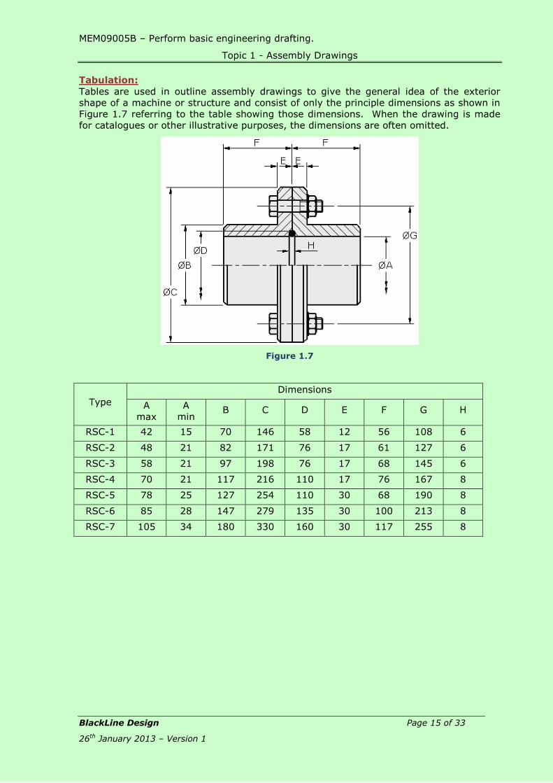
Tabulation:
Tables are used in outline assembly drawings to give the general idea of the exterior
shape of a machine or structure and consist of only the principle dimensions as shown in
Figure 1.7 referring to the table showing those dimensions. When the drawing is made
for catalogues or other illustrative purposes, the dimensions are often omitted.
Figure 1.7
Type
Dimensions
A
max
A
min B C D E F G H
RSC-1 42 15 70 146 58 12 56 108 6
RSC-2 48 21 82 171 76 17 61 127 6
RSC-3 58 21 97 198 76 17 68 145 6
RSC-4 70 21 117 216 110 17 76 167 8
RSC-5 78 25 127 254 110 30 68 190 8
RSC-6 85 28 147 279 135 30 100 213 8
RSC-7 105 34 180 330 160 30 117 255 8

MEM09005B – Perform basic engineering drafting.
Topic 1 - Assembly Drawings
BlackLine Design Page 16 of 33
26th January 2013 – Version 1
How Do The Parts Fit Together? The draftsperson should be competent in being able to identify from the engineer’s
sketches, the way the different components fit together to form the assembly. The
secret is to look for similar or matching dimensions and features including:
Threads: A shaft could have a threaded end which screws onto a mating pulley or
fastening. e.g. M10x0.75
Shape: A component could have a dovetailed feature which would over another
matching dovetail.
Taper or
Angle:
A taped face on one object will almost certainly fit against the face of
another angled surface. eg. 16°.
In the above example the two angular dimensions form the same angle
to the horizontal, the 16° is given from the horizontal while the 74° is
given from the vertical; both add up to 90°.
Dimensions: A dimension on one part will probably match up to the same dimension
on another part even though the parts may have different shapes.

MEM09005B – Perform basic engineering drafting.
Topic 1 - Assembly Drawings
BlackLine Design Page 17 of 33
26th January 2013 – Version 1
Toleranced
Dimensions:
Although the toleranced dimensions of two mating parts may not have
the same upper and lower values, they will be very similar with the same
basic size.
Keys and
Keyways:
Many shafts and pulleys etc are locked together by keys which are
generally a square or rectangular length of metal. On the drawing the
keyway is identified by a groove in the shaft and pulley.
eg. 10x3 Keyway.
Holes: Mounting holes in one component generally mate with another set of
holes in a second and/or third component. eg. 8-16 Holes on
150PCD that could match holes with the same PCD.
Fastenings: A fastening will probably be threaded which will screw into a mating hole,
eg. M10x15 Deep. The shape of the head of the fastening may also
determine its location with a part, eg. an M10x30 Socket Head Cap
Screw would fit into a counterbored hole on one part which would be
identified Drill 10 C’bore 16x10 deep with a matching pitch of 125.
Ø20.0519.95
Ø20.0519.95
10x3 Keyway
10x3 Keyway
8-Ø16 Holeson 150PCD
8-Ø16 Holeson 150PCD
Drill Ø7.8x20 DeepTap M10x15 Deep
on 125PCD 8-Ø10 Holeson 125PCD

MEM09005B – Perform basic engineering drafting.
Topic 1 - Assembly Drawings
BlackLine Design Page 18 of 33
26th January 2013 – Version 1
Skill Practice Exercise
Skill Practice Exercise MEM09005-SP-0101
Create an assembly drawing of the Stripper Cylinder on a standard A2 sheet using the
template drawing provided on the network drive called Stripper Cylinder and the details
provided below. Include the Front and Top Views with the Front View being fully
sectioned. Include a Parts List, overall dimensions and cross-referencing. The drawing
files for the Set Screws are stored in the Fastenings folder. Save the drawing to your
work area as MEM09005-SP-0101; the drawing number is MEM09005-SP-0101.
Stripper Cylinder Assembly

MEM09005B – Perform basic engineering drafting.
Topic 1 - Assembly Drawings
BlackLine Design Page 19 of 33
26th January 2013 – Version 1
Item 1 - Stripper Cylinder Body
Material – Cast Iron
Item 2 – Piston Rod
Material – Mild Steel

MEM09005B – Perform basic engineering drafting.
Tables
BlackLine Design Page 20 of 33
26th January 2013 – Version 1
Tables
Table 1 – Internal Circlips
Most sizes over 170mm are without lugs Measurements are in mm Code
No. Bore
B
Circlip Dimensions Groove Dimensions
t Tol d Tol Cb b L h G Tol W n
8 0.80 +0.00
-0.05
8.7
+0.36
-0.10
3.0 1.1 2.4 1.0 8.4 +0.90
-0.00
0.9 0.6 INT0080
9 0.80 9.8 3.7 1.3 2.5 1.0 9.4 0.9 0.6 INT0090
10 1.00
+0.00
-0.06
10.8 3.3 1.4 3.2 1.2 10.4
+0.11
-0.00
1.0 0.6 INT0100
11 1.00 11.8 4.1 1.5 3.3 1.2 11.4 1.1 0.6 INT0110
12 1.00 13.0 4.9 1.7 3.4 1.5 12.5 1.1 0.8 INT0120
13 1.00 14.1 5.4 1.8 3.6 1.5 13.6 1.1 0.9 INT0130
14 1.00 15.1 6.2 1.9 3.7 1.7 14.6 1.1 0.9 INT0140
15 1.00 16.2 7.2 2.0 3.7 1.7 15.7 1.1 1.2 INT0150
16 1.00 17.3 8.0 2.0 3.8 1.7 16.8 1.1 1.2 INT0160
17 1.00 18.3
+0.42
-0.13
8.8 2.1 3.9 1.7 17.8 1.1 1.5 INT0170
18 1.00 19.5 9.4 2.2 4.1 2.0 19.0
+0.13
-0.00
1.1 1.5 INT0180
19 1.00 20.5 10.4 2.3 4.1 2.0 20.0 1.1 1.5 INT0190
20 1.00 21.5 11.2 2.4 4.2 2.0 21.0 1.1 1.5 INT0200
21 1.00 22.5 12.2 2.5 4.2 2.0 22.0 1.1 1.5 INT0210
22 1.00 26.5 13.2 2.6 4.2 2.0 23.0 1.3 1.5 INT0220
23 1.20 24.6
+0.42
-0.21
14.2 2.5 4.2 2.0 24.1 1.3 1.5 INT0230
24 1.20 25.9 14.8 2.6 4.4 2.0 25.2
-0.21
-0.00
1.3 1.8 INT0240
25 1.20 26.9 15.5 2.7 4.5 2.0 26.2 1.3 1.8 INT0250
26 1.20 27.9 16.1 2.8 4.7 2.0 27.2 1.3 1.8 INT0260
27 1.20 29.1 17.1 2.9 4.7 2.0 28.4 1.3 2.1 INT0270
28 1.20 30.1
+0.50
-0.25
17.9 2.9 4.8 2.0 29.4 1.3 2.1 INT0280
29 1.20 31.1 18.4 3.0 4.8 2.0 30.4
+0.25
-0.00
1.3 2.1 INT0290
30 1.20 32.1 19.9 3.0 4.8 2.0 31.4 1.3 2.1 INT0300
31 1.20 33.4 20.0 3.2 5.2 2.5 32.7 1.3 2.6 INT0310
32 1.20 33.4 20.6 3.2 5.4 2.5 33.7 1.3 2.6 INT0320
33 1.20 35.5 21.6 3.3 5.4 2.5 34.7 1.3 2.6 INT0330
34 1.50 36.5 22.6 3.3 5.4 2.5 35.7 1.6 2.6 INT0340
35 1.50 37.8 23.6 3.4 5.4 2.5 37.0 1.6 3.0 INT0350
36 1.50 38.8 24.6 3.5 5.4 2.5 38.0 1.6 3.0 INT0360

MEM09005B – Detail Drafting 2
Tables
BlackLine Design Page 21 of 33
26th January 2013 – Version 1
Most sizes over 170mm are without lugs Measurements are in mm Code
No. Bore
B
Circlip Dimensions Groove Dimensions
t Tol d Tol Cb b L h G Tol W n
37 1.50
+0.00
-0.06
39.8 +0.50
-0.25
25.4 3.6 5.5 2.5 39.0
+0.25
-0.00
1.6 3.0 INT0370
38 1.50 40.8 26.4 3.7 5.5 2.5 40.0 1.6 3.0 INT0380
39 1.50 42.0
+0.90
-0.39
27.2 3.8 5.6 2.5 41.0 1.6 3.0 INT0390
40 1.75 43.5 27.8 3.9 5.8 2.5 42.5 1.8 3.0 INT0400
41 1.75 44.5 28.6 4.0 5.9 2.5 43.5 1.8 3.8 INT0410
42 1.75 45.5 29.6 4.1 5.9 2.5 44.5 1.8 3.8 INT0420
43 1.75 46.5 30.6 4.2 5.9 2.5 45.5 1.8 3.8 INT0430
44 1.75 47.5 31.4 4.2 6.0 2.5 46.5 1.8 3.8 INT0440
45 1.75 48.5 32.0 4.3 6.2 2.5 47.5 1.8 3.8 INT0450
46 1.75 49.5 32.7 4.4 6.3 2.5 48.5 1.8 3.8 INT0460
47 1.75 50.5
+1.10
-0.46
33.5 4.4 6.4 2.5 49.5 1.8 3.8 INT0470
48 1.75 51.5 34.5 4.5 6.4 2.5 50.5
+0.30
-0.00
1.8 3.8 INT0480
50 2.00
+0.00
-0.07
54.2 36.3 4.6 6.5 2.5 53.0 2.15 4.5 INT0500
51 2.00 55.2 37.3 4.7 6.5 2.5 54.0 2.15 4.5 INT0510
52 2.00 56.2 37.9 4.7 6.7 2.5 55.0 2.15 4.5 INT0520
53 2.00 57.2 38.9 4.9 6.7 2.5 56.0 2.15 4.5 INT0530
54 2.00 58.2 39.9 5.0 6.7 2.5 57.0 2.15 4.5 INT0540
55 2.00
+0.00
-0.07
59.2
+1.10
-0.46
40.7 5.0 6.8 2.5 58.0 2.15 4.5 INT0550
56 2.00 60.2 41.7 5.1 6.8 2.5 59.0 2.15 4.5 INT0560
57 2.00 61.2 42.7 5.1 6.8 2.5 60.0 2.15 4.5 INT0570
58 2.00 62.2 43.5 5.2 6.9 2.5 61.0 2.15 4.5 INT0580
60 2.00 64.2 44.7 5.4 7.3 2.5 63.0 2.15 4.5 INT0600
62 2.00 66.2 46.7 5.5 7.3 2.5 65.0 2.15 4.5 INT0620
63 2.00 67.2 47.7 5.6 7.3 2.5 66.0 2.15 4.5 INT0630
64 2.00 68.2 48.2 5.7 7.5 2.5 67.0 2.15 4.5 INT0640
65 2.50 69.2 49.0 5.8 7.6 3.0 68.0 2.65 4.5 INT0650
67 2.50 71.5 50.8 6.0 7.7 3.0 70.0 2.65 4.5 INT0670
68 2.50 72.5 51.6 6.1 7.8 3.0 71.0 2.65 4.5 INT0680
70 2.50 74.5 53.6 6.2 7.8 3.0 73.0 2.65 4.5 INT0700
72 2.50 76.5 55.6 6.4 7.8 3.0 75.0 2.65 4.5 INT0720
75 2.50 79.5 58.6 6.6 7.8 3.0 78.0 2.65 4.5 INT0750
77 2.50 81.5 60.4 6.7 7.9 3.0 80.0 2.65 4.5 INT0770
78 2.50 82.5
+1.30
-0.54
60.1 6.8 8.5 3.0 81.0
+0.35
-0.00
2.65 5.3 INT0780
80 2.50 85.5 62.1 7.0 8.5 3.0 83.5 2.65 5.3 INT0800
82 2.50 87.5 64.1 7.0 8.5 3.0 85.5 2.65 5.3 INT0820
85 3.00
+0.00
-0.08
90.5 66.9 7.2 8.6 3.5 88.5 2.65 5.3 INT0850
87 3.00 92.5 68.9 7.3 8.6 3.5 90.5 3.15 5.3 INT0870
88 3.00 93.5 69.9 7.4 8.6 3.5 91.5 3.15 5.3 INT0880
90 3.00 95.5 71.9 7.6 8.6 3.5 93.5 3.15 5.3 INT0900
92 3.00 97.5 73.7 7.8 8.7 3.5 95.5 3.15 5.3 INT0920

MEM09005B – Detail Drafting 2
Tables
BlackLine Design Page 22 of 33
26th January 2013 – Version 1
Most sizes over 170mm are without lugs Measurements are in mm Code
No. Bore
B
Circlip Dimensions Groove Dimensions
t Tol d Tol Cb b L h G Tol W n
95 3.00 +0.00
-0.08
100.5
+1.30
-0.54
76.5 8.1 8.8 3.5 98.5
+0.35
-0.00
3.15 5.3 INT0950
97 3.00 102.5 78.5 8.2 8.8 3.5 100.5 3.15 5.3 INT0970
98 3.00 103.5 79.0 8.3 9.0 3.5 101.5 3.15 5.3 INT0980
100 3.00 105.5 80.6 8.4 9.2 3.5 103.5 3.15 5.3 INT1000
102 4.00
+0.00
-0.10
108.0 82.0 8.5 9.5 3.5 106.0
+0.54
-0.00
4.15 6.0 INT1020
105 4.00 112.0 85.0 8.7 9.5 3.5 109.0 4.15 6.0 INT1050
108 4.00 115.0 88.0 8.9 9.5 3.5 112.0 4.15 6.0 INT1080
110 4.00 117.0 88.2 9.0 10.4 3.5 114.0 4.15 6.0 INT1100
112 4.00 119.0 90.0 9.1 10.5 3.5 116.0 4.15 6.0 INT1120
115 4.00 122.0
+1.50
-0.63
93.0 9.3 10.5 3.5 119.0 4.15 6.0 INT1150
120 4.00 127.0 96.9 9.7 11.0 3.5 124.0
+0.63
-0.00
4.15 6.0 INT1200
125 4.00 132.0 101.9 10.0 11.0 4.00 129.0 4.15 6.0 INT1250
130 4.00 137.0 106.9 10.2 11.0 4.00 134.0 4.15 6.0 INT1300
135 4.00 142.0 111.5 10.5 11.2 4.00 139.0 4.15 6.0 INT1350
140 4.00 147.0 116.5 10.7 11.2 4.00 144.0 4.15 6.0 INT1400
145 4.00 152.0 121.0 10.9 11.4 4.00 149.0 4.15 6.0 INT1450
150 4.00 158.0 124.8 11.2 12.0 4.00 155.0 4.15 7.5 INT1500
155 4.00 164.0 129.8 11.4 12.0 4.00 160.0 4.15 7.5 INT1550
160 4.00 169.0 132.7 11.6 13.0 4.00 165.0 4.15 7.5 INT1600
165 4.00 174.5 137.7 11.8 13.0 4.00 170.0 4.15 7.5 INT1650
170 4.00 179.5 141.6 12.2 13.5 4.00 175.0 4.15 7.5 INT1700
175 4.00 184.5
+1.70
-0.72
146.6 12.7 13.5 4.00 180.0 4.15 7.5 INT1750
180 4.00 189.5 150.2 13.2 14.2 4.00 185.0
+0.72
-0.00
4.15 7.5 INT1800
185 4.00 194.5 155.2 13.7 14.2 4.00 190.5 4.15 7.5 INT1850
190 4.00 199.5 160.2 13.8 14.2 4.00 195.0 4.15 7.5 INT1900
195 4.00 204.5 165.2 13.8 14.2 4.00 200.0 4.15 7.5 INT1950
200 4.00 209.5 170.2 14.0 14.2 4.00 205.0 4.15 7.5 INT2000

MEM09005B – Detail Drafting 2
Tables
BlackLine Design Page 23 of 33
26th January 2013 – Version 1
Table 2 – External Circlips
Most sizes over 170mm are without lugs Measurements are in mm Code
No. Shaft Circlip Dimensions Groove Dimensions
t Tol d Tol Cs b L h G Tol W n
3 0.40
+0.00
-0.05
2.7
+0.04
-0.15
7.0 0.8 1.9 1.0 2.8 +0.00
-0.04 0.5 0.3 EXT0030
4 0.40 3.7 8.6 0.9 2.2 1.0 3.8 +0.00
-0.048
0.5 0.3 EXT0040
5 0.60 4.7 10.3 1.1 2.5 1.0 4.8 0.7 0.3 EXT0050
6 0.70 5.6 11.7 1.3 2.7 1.2 5.7 0.8 0.5 EXT0060
7 0.80 6.5 +0.06
-0.18
13.5 1.4 3.1 1.2 6.7
+0.00
-0.06
0.9 0.5 EXT0070
8 0.80 7.4 14.7 1.5 3.2 1.2 7.6 1.1 0.6 EXT0080
9 0.80
+0.00
-0.06
8.4 16.0 1.7 3.3 1.2 8.6 1.1 0.6 EXT0090
10 1.00 9.3
+0.10
-0.36
17.0 1.8 3.3 1.5 9.6 1.1 0.6 EXT0100
11 1.00 10.2 18.0 1.8 3.3 1.5 10.5
+0.00
-0.11
1.1 0.8 EXT0110
12 1.00 11.0 19.0 1.8 3.3 1.7 11.5 1.1 0.8 EXT0120
13 1.00 11.9 20.2 2.0 3.4 1.7 12.4 1.1 0.9 EXT0130
14 1.00 12.9 21.4 2.1 3.5 1.7 13.4 1.1 0.9 EXT0140
15 1.00 13.8 22.6 2.2 3.6 1.7 14.3 1.1 1.1 EXT0150
16 1.00 14.7 23.8 2.2 3.7 1.7 15.2 1.1 1.2 EXT0160
17 1.00 15.7 25.0 2.3 3.8 1.7 16.2 1.1 1.2 EXT0170
18 1.00 16.5 26.2 2.4 3.9 2.0 17.0 1.3 1.5 EXT0180
19 1.00 17.5 27.2 2.5 3.9 2.0 18.0 1.3 1.5 EXT0190
20 1.00 18.5
+0.13
-0.42
28.4 2.6 4.0 2.0 19.0
+0.00
-0.21
1.3 1.5 EXT0200
21 1.00 19.5 29.6 2.7 4.0 2.0 20.0 1.3 1.5 EXT0210
22 1.00 20.5 30.8 2.8 4.2 2.0 21.0 1.3 1.5 EXT0220
23 1.20 21.5 32.0 2.9 4.3 2.0 22.0 1.3 1.5 EXT0230
24 1.20 22.2
+0.21
-0.42
33.2 3.0 4.4 2.0 22.9 1.3 1.7 EXT0240
25 1.20 23.2 34.2 3.0 4.4 2.0 23.9 1.3 1.7 EXT0250
26 1.20 24.2 35.5 3.1 4.5 2.0 24.9 1.3 1.7 EXT0260
27 1.20 24.9 36.7 3.1 4.6 2.0 25.6 1.3 2.1 EXT0270
28 1.20 25.9 37.9 3.2 4.7 2.0 26.6 1.6 2.1 EXT0280

MEM09005B – Detail Drafting 2
Tables
BlackLine Design Page 24 of 33
26th January 2013 – Version 1
Most sizes over 170mm are without lugs Measurements are in mm Code
No. Shaft Circlip Dimensions Groove Dimensions
t Tol d Tol Cs b L h G Tol W n
29 1.20
+0.00
-0.06
26.9 +0.21
-0.42
39.1 3.4 4.8 2.0 27.6 +0.00
-0.21
1.6 2.1 EXT0290
30 1.20 27.9 40.5 3.5 5.0 2.0 28.6 1.6 2.1 EXT0300
31 1.20 28.6 41.5 3.5 5.0 2.5 29.3 1.6 2.6 EXT0310
32 1.20 29.6
+0.25
-0.50
43.0 3.6 5.2 2.5 30.3
+0.00
-0.25
1.6 2.6 EXT0320
33 1.20 30.5 44.0 3.7 5.2 2.5 31.3 1.6 2.6 EXT0330
34 1.50 31.5 45.5 3.8 5.4 2.5 32.3 1.6 2.6 EXT0340
35 1.50 32.2 46.8 3.9 5.6 2.5 33.0 1.6 3.0 EXT0350
36 1.50 33.2 47.8 4.0 5.6 2.5 34.0 1.85 3.0 EXT0360
37 1.50 34.2 49.0 4.1 5.7 2.5 35.0 1.85 3.0 EX370T0
38 1.50 35.2 50.2 4.2 5.8 2.5 36.0 1.85 3.0 EXT0380
39 1.50 36.0 51.4 4.3 5.9 2.5 37.0 1.85 3.8 EXT0390
40 1.75 36.5 52.6 4.4 6.0 2.5 37.5 1.85 3.8 EXT0400
41 1.75 37.5 54.1 4.5 6.2 2.5 38.5 1.85 3.8 EXT0410
42 1.75 38.5
+0.39
-0.90
55.7 4.5 6.5 2.5 39.5 1.85 3.8 EXT0420
43 1.75 39.5 56.7 4.6 6.6 2.5 40.5 1.85 3.8 EXT0430
44 1.75 40.5 57.9 4.6 6.7 2.5 41.5 1.85 3.8 EXT0440
45 1.75 41.5 59.1 4.7 6.7 2.5 42.5 1.85 3.8 EXT0450
46 1.75 42.5 60.1 4.8 6.8 2.5 43.5 1.85 3.8 EXT0460
47 1.75 43.5 61.3 4.9 6.9 2.5 44.5 1.85 3.8 EXT0470
48 1.75 44.5 62.5 5.0 6.9 2.5 45.5 1.85 3.8 EXT0480
50 2.00
+0.00
-0.07
45.8 64.5 5.1 6.9 2.5 47.0 2.15 4.5 EXT0500
51 2.00 46.8 65.7 5.2 7.0 2.5 48.0 2.15 4.5 EXT0510
52 2.00 47.8 66.7 5.2 7.0 2.5 49.0 2.15 4.5 EXT0520
53 2.00 48.8 68.0 5.3 7.1 2.5 50.0 2.15 4.5 EXT0530
54 2.00 49.8
+0.46
-1.10
69.0 5.3 7.1 2.5 51.0
+0.00
-0.30
2.15 4.5 EXT0540
55 2.00 50.8 70.2 5.4 7.2 2.5 52.0 2.15 4.5 EXT0550
56 2.00 51.8 71.6 5.5 7.3 2.5 53.0 2.15 4.5 EXT0560
57 2.00 52.8 72.4 5.5 7.3 2.5 54.0 2.15 4.5 EXT0570
58 2.00 53.8 73.6 5.6 7.3 2.5 55.0 2.15 4.5 EXT0580
60 2.00
+0.00
-0.07
55.8
+0.46
-1.10
75.6 5.8 7.4 2.5 57.0
+0.00
-0.30
2.15 4.5 EXT0600
62 2.00 57.8 77.8 6.0 7.5 2.5 59.0 2.15 4.5 EXT0620
63 2.00 58.8 79.0 6.2 7.6 2.5 60.0 2.15 4.5 EXT0630
65 2.50 62.5 81.4 6.3 7.8 3.0 62.0 2.65 4.5 EXT0650
67 2.50 63.5 83.6 6.4 7.9 3.0 64.0 2.65 4.5 EXT0670
68 2.50 63.5 84.4 6.5 8.0 3.0 65.0 2.65 4.5 EXT0680
70 2.00 65.5 87.0 6.6 8.1 3.0 67.0 2.65 4.5 EXT0700
72 2.00 67.5 89.2 6.8 8.2 3.0 69.0 2.65 4.5 EXT0720
75 2.00 70.5 92.7 7.0 8.4 3.0 72.0 2.65 4.5 EXT0750
77 2.00 72.5 94.9 7.2 8.5 3.0 74.0 2.65 4.5 EXT0770
78 2.50 73.5 96.1 7.3 8.6 3.0 75.0 2.65 4.5 EXT0780
MEM09005B – Detail Drafting 2
Tables
BlackLine Design Page 25 of 33
26th January 2013 – Version 1
Most sizes over 170mm are without lugs Measurements are in mm Code
No. Shaft Circlip Dimensions Groove Dimensions
t Tol d Tol Cs b L h G Tol W n
80 2.50 +0.00
-0.07
74.5 +0.46
-1.10
98.1 7.4 8.6 3.0 76.5 +0.00
-0.30
2.65 5.3 EXT0800
82 3.00 76.5 100.3 7.6 8.7 3.0 78.5 2.65 5.3 EXT0820
85 3.00
+0.00
-0.08
79.5 100.3 7.8 8.7 3.5 81.5
+0.00
-0.35
3.15 5.3 EXT0850
87 3.00 81.5
+0.54
-1.30
105.5 7.9 8.8 3.5 83.5 3.15 5.3 EXT0870
88 3.00 82.5 106.5 8.0 8.8 3.5 84.5 3.15 5.3 EXT0880
90 3.00 84.5 108.5 8.2 8.8 3.5 86.5 3.15 5.3 EXT0900
92 3.00 86.5 111.0 8.4 9.0 3.5 88.5 3.15 5.3 EXT0920
95 3.00 89.5 114.8 8.6 9.4 3.5 91.5 3.15 5.3 EXT0950
97 3.00 91.5 116.8 8.8 9.4 3.5 93.5 3.15 5.3 EXT0970
98 3.00 92.5 118.0 9.0 9.5 3.5 94.5 3.15 5.3 EXT0980
100 3.00 94.5 120.2 9.0 9.6 3.5 96.5 3.15 5.3 EXT1000
102 4.00
+0.00
-0.10
95.0 122.4 9.2 9.7 3.5 98.0
+0.00
-0.54
4.15 6.0 EXT1020
105 4.00 98.0 125.8 9.3 9.9 3.5 101.0 4.15 6.0 EXT1050
108 4.00 101.0 129.0 9.5 10.0 3.5 104.0 4.15 6.0 EXT1080
110 4.00 103.0 131.2 9.6 10.1 3.5 106.0 4.15 6.0 EXT1100
112 4.00 105.0 133.7 9.7 10.3 3.5 108.0 4.15 6.0 EXT1120
115 4.00 108.0 133.7 9.8 10.6 3.5 111.0 4.15 6.0 EXT1150
120 4.00 113.0 143.1 10.2 11.0 3.5 116.0 4.15 6.0 EXT1200
125 4.00 118.0 149.0 10.4 11.4 4.0 121.0
+0.00
-0.63
4.15 6.0 EXT1250
130 4.00 123.0
+0.63
-1.50
154.4 10.7 11.6 4.0 126.0 4.15 6.0 EXT1300
135 4.00 128.0 159.8 11.0 11.8 4.0 131.0 4.15 6.0 EXT1350
140 4.00 133.0 165.2 11.2 12.0 4.0 136.0 4.15 6.0 EXT1400
145 4.00 138.0 170.6 11.5 12.2 4.0 141.0 4.15 6.0 EXT1450
150 4.00 142.0 177.3 11.8 13.0 4.0 145.0 4.15 6.0 EXT1500
155 4.00 146.0 182.3 12.0 13.0 4.0 150.0 4.15 7.5 EXT1550
160 4.00 151.0 188.0 12.2 13.3 4.0 155.0 4.15 7.5 EXT1600
165 4.00 155.5 193.4 12.5 13.5 4.0 160.0 4.15 7.5 EXT1650
170 4.00 160.5 198.4 12.9 13.5 4.0 165.0 4.15 7.5 EXT1700
175 4.00 165.5 203.4 12.9 13.5 4.0 170.0 4.15 7.5 EXT1750
180 4.00 170.5 210.0 14.0 14.2 4.0 175.0 4.15 7.5 EXT1800
185 4.00 175.5 215.0 14.0 14.2 4.0 180.0 4.15 7.5 EXT1850

MEM09005B – Detail Drafting 2
Tables
BlackLine Design Page 26 of 33
26th January 2013 – Version 1
Table 3 – Deep Groove Ball Bearings
Principal Dimensions
Mass Part No. Dimensions Abutment & Fillet
Dimensions
mm kg mm mm
d D B d1 D1 r da Da max Ra Max
17 26 5 0.0082 61803 20.2 23.2 0.3 19 24 0.3
35 8 0.032 16003 22.8 29.5 0.3 19 33 0.3
35 10 0.039 6003 22.8 29.5 0.3 19 33 0.3
40 12 0.065 6203 2402 32.9 0.6 21 36 0.6
47 14 0.12 6303 26.5 37.6 1 22 42 1
62 17 0.27 6403 32.4 47.4 1.1 23.5 55.5 1
20 32 7 0.018 61804 24 28.3 0.3 22 30 0.3
42 8 0.050 16004 27.2 34.6 0.3 22 40 0.3
42 12 0.069 6004 27.2 35.1 0.6 24 38 0.6
47 14 0.11 6204 28.5 38.7 1 25 42 1
52 15 0.14 6304 30.3 42.1 1.1 26.5 45.5 1
72 19 0.40 6404 37.1 55.6 1.1 26.5 65.5 1
25 37 7 0.022 61805 29 33 0.3 27 35 0.3
47 8 0.060 16005 33.3 40.7 0.3 27 45 0.3
47 12 0.080 6005 32 40.3 0.6 29 43 0.6
52 15 0.13 6205 34 44.2 1 30 47 1
62 17 0.23 6305 36.6 50.9 1.1 31.5 55.5 1
80 21 0.53 6405 45.4 63.8 1.5 33 72 1.5
30 52 7 0.026 61806 33.8 38.2 0.3 32 40 0.3
55 9 0.085 16006 38 47.3 0.3 32 53 0.3
55 13 0.12 6006 38.2 47.1 1 35 50 1
62 16 0.20 6206 40.3 52.1 1 35 57 1
72 19 0.35 6306 44.6 59.9 1.1 36.5 65.5 1
90 23 0.74 6406 50.3 70.7 1.5 38 82 1.5

MEM09005B – Detail Drafting 2
Tables
BlackLine Design Page 27 of 33
26th January 2013 – Version 1
35 47 7 0.030 61807 38.8 43.2 0.3 37 45 0.3
62 9 0.11 16007 44 53.3 0.3 37 60 0.3
62 14 0.16 6007 43.7 53.6 1 40 57 1
72 17 0.29 6207 46.9 60.6 1.1 41.5 65.5 1
80 21 0.46 6307 49.5 66.1 1.5 43 72 1.5
100 25 0.95 6407 57.4 80.6 1.5 43 92 1.5
40 52 7 0.034 61808 43.8 48.2 0.3 42 50 0.3
68 9 0.13 16008 49.4 57 0.3 42 66 0.3
68 15 0.19 6008 49.2 59.1 1 45 63 1
80 18 0.37 6208 52.6 67.9 1.1 46.5 73.5 1
90 23 0.63 6308 56.1 74.7 1.5 48 82 1.5

MEM09005B – Detail Drafting 2
Tables
BlackLine Design Page 28 of 33
26th January 2013 – Version 1
Table 4 – Self Aligning Ball Bearings
Boundary Dimensions Mass Part Number Dimensions Abutment & Fillet
Dimensions
d D B Cyl.
Bore
Taper
Bore
d2 D1 R
Min
da
Min
Da
max
Ra
max
mm kg mm mm
17 40 12 0.16 1203 - 24.2 33.7 1 21 36 0.6
40 16 0.19 2203 - 23.5 34.3 1 21 36 0.6
47 14 0.29 1303 - 26.4 38.3 1.5 22 42 1
47 19 0.35 2303 - 25.8 39.4 1.5 22 42 1
20 47 14 0.26 1204 - 28.9 39.1 1.5 25 42 1
47 18 0.31 2204 - 28.0 40.4 1.5 25 42 1
52 15 0.35 1304 - 31.3 43.6 2 26.5 45.5 1
52 21 0.46 2304 - 28.8 43.7 2 26.5 45.5 1
25 52 15 0.31 1205 1205K 33.1 44.9 1.5 30 47 1
52 18 0.35 2205 2205K 33.0 44.7 1.5 30 47 1
62 17 0.57 1305 1305K 37.8 52.5 2 31.5 55.5 1
62 24 0.75 2305 2305K 35.2 52.5 2 31.5 55.5 1
30 62 16 0.48 1206 1206K 40.1 53.2 1.5 35 57 1
62 20 0.57 2206 2206K 40.0 53.0 1.5 35 57 1
72 19 0.86 1306 1306K 44.9 60.9 2 36.5 65.5 1
72 27 1.10 2306 2306K 41.7 60.9 2 36.5 65.5 1
MEM09005B – Detail Drafting 2
Tables
BlackLine Design Page 29 of 33
26th January 2013 – Version 1
Boundary Dimensions Mass Part Number Dimensions Abutment & Fillet
Dimensions
d D B Cyl.
Bore
Taper Bore
d2 D1 R
Min
da
Min
Da
max
Ra
max
mm kg mm mm
35 72 17 0.71 1207 1207K 47.5 60.7 2 41.5 65.5 1
72 23 0.88 2207 2207K 46.0 62.2 2 41.5 65.5 1
80 21 1.10 1307 1307K 51.5 69.5 2.5 43 72 1.5
80 31 1.50 2307 2307K 46.5 68.4 2.5 43 72 1.5
40 80 18 0.93 1208 1208K 53.6 68.8 2 46.5 73.5 1
80 23 1.10 2208 2208K 52.4 68.8 2 46.5 73.5 1
90 23 1.60 1308 1308K 57.5 76.8 2.5 48 82 1.5
90 33 2.05 2308 2308K 53.5 76.8 2.5 48 82 1.5

MEM09005B – Detail Drafting 2
Tables
BlackLine Design Page 30 of 33
26th January 2013 – Version 1
Table 5 - Angular Contact Ball Bearing
Principal Dimensions
Mass Part No. Dimensions Abutment & Fillet
Dimensions
D d B d1 D1 R a da Da
max
Ra
max
mm kg mm mm
20 42 12 0.33 7004 C 26.9 35.1 1 10 25 37 0.6
42 24 0.68 2 x 7004 CG 26.9 35.1 1 10 25 37 0.6
47 14 0.48 7204 C 29.1 38.7 1.5 12 26 41 1
47 14 0.58 7204 B 30.7 36.7 1.5 21 26 41 1
47 28 0.97 2 x 7204 CG 29.1 38.7 1.5 12 26 41 1
47 28 1.08 2 x 7024 BG 30.7 36.7 1.5 21 26 41 1
52 15 0.73 304 B 32.7 39.9 2 23 27 45 1
52 30 1.45 2 x 7304 BG 32.7 39.9 2 23 27 45 1
25 47 12 0.40 7005 C 31.9 40.1 1 11 30 42 0.6
47 24 0.77 2 x 7005 CG 31.9 40.1 1 11 30 42 0.6
52 15 0.57 7205 C 34.1 43.7 1.5 13 31 46 1
52 15 0.68 7205 B 36.3 42.3 1.5 24 31 46 1
52 30 1.17 2 x 7205 CG 34.1 43.7 1.5 13 31 46 1
52 30 1.36 2 x 7205 BG 36.3 42.3 1.5 24 31 46 1
62 17 1.17 7205 B 39.6 48 2 27 32 55 1
62 34 2.31 2 x 7305 BG 39.6 48 2 27 32 55 1

MEM09005B – Detail Drafting 2
Tables
BlackLine Design Page 31 of 33
26th January 2013 – Version 1
Principal
Dimensions Mass Part No. Dimensions
Abutment & Fillet
Dimensions
D d B d1 D1 R a da Da
max
Ra
max
mm kg mm mm
30 55 13 0.57 7006 C 38.1 46.9 1.5 12 36 49 1
55 26 1.17 2 x 7006 CG 38.1 46.9 1.5 12 36 49 1
62 16 0.92 7206 C 40.3 51.7 1.5 14 36 56 1
62 16 1.01 7206 B 42.7 49.9 1.5 27 36 56 1
62 32 1.85 2 x 7206 CG 40.3 51.7 1.5 14 36 56 1
62 32 2.05 2 x 7206 BG 42.7 49.9 1.5 27 36 56 1
72 19 1.74 7306 B 47.7 57 2 31 37 65 1
72 38 3.52 2 x 7306 BG 47.7 57 2 31 37 65 1
35 62 14 0.77 7007 C 43.7 53.3 1.5 14 41 56 1
62 28 1.56 2 x 7007 CG 43.7 53.3 1.5 14 41 56 1
72 17 1.32 7207 C 47 60 2 16 42 65 1
72 17 1.45 7207 B 49.6 58 2 31 42 65 1
72 34 2.64 2 x 7207 CG 47 60 2 16 42 65 1
72 34 2.86 2 x 7207 BG 49.6 58 2 31 42 65 1
80 21 2.31 7307 B 52.8 63 2.5 35 44 71 1
80 42 4.62 2 x 7307 BG 52.8 63 2.5 35 44 71 1

MEM09005B – Detail Drafting 2
Tables
BlackLine Design Page 32 of 33
26th January 2013 – Version 1
Table 6 - Cylindrical Roller Bearings
Principal Dimensions
Part Number Dimensions
d D B kg NU NJ NUP N d1 D1 E F R R1
mm
12 22 8 0.11 NU 1204 E - - - - 18.6 19.5 13.5 0.5 0.25
22 10 0.13 NU 124 NJ 124 NUP 124 N 124 14 18.6 19.5 13.5 0.5 0.25
28 12 0.16 - NJ 124 E NUP 1204 E - 17.8 23.7 25 16 0.5 0.25
30 12 0.18 NU 1204 NJ 1204 - N 1204 19.1 25.4 27 17 0.5 0.25
14 28 8 0.15 NU 1404 E - - - - 23.7 25 17 0.5 0.25
30 10 0.18 NU 144 NJ 144 NUP 144 N 144 19.1 25.4 27 18.5 0.5 0.25
36 12 0.22 - NJ 1404 E NUP 1404 E - 22.9 30.4 32 22 0.5 0.25
37 12 0.24 NU 1404 NJ 1404 - N 1404 23.6 31.2 33 23 0.5 0.25
16 30 8 0.19 NU 1604 E - - - - 25.4 27 18 0.5 0.25
32 10 0.22 NU 1604 NJ 164 NUP 164 N 164 20.4 27.0 28.5 19.5 0.5 0.25
36 10 0.25 - NJ 1604 E NUP 1604 E - 22.9 30.4 32 22 0.5 0.25
36 12 0.29 NU 164 NJ 1604 - N 1604 22.9 30.4 32 22 0.5 0.25
18 32 10 0.28 NU 1804 - - - - 27.0 28.5 19.5 0.5 0.25
36 10 0.32 NU 1804 E NJ 184 NUP 184 N 184 22.9 30.4 32 20 0.5 0.25
40 12 0.40 - NJ 1804 E NUP 1804 E - 25.5 33.8 37.5 24.5 0.5 0.25
40 13 0.41 NU 184 NJ 1804 - N 1804 25.5 33.8 37.5 24.5 0.5 0.25
20 42 14 0.44 NU 2004 E - - - - 35.5 37.5 25.5 1 0.5
47 14 0.53 NU 204 NJ 204 NUP 204 N 204 30 37.3 40 27 1.5 1
47 14 0.53 - NJ 204 E NUP 204 E - 29.7 38.8 41.5 26.5 1.5 1
47 18 0.68 NU 2204 NJ 2204 - - 30 37.3 40 27 1.5 1
47 18 0.72 - NJ 2204 E - - 29.7 38.8 41.5 26.5 1.5 1
52 15 0.72 NU 304 NJ 304 NUP 304 N 304 31.8 40.5 44.5 28.5 2 1
52 15 0.77 NU 304 E NJ 304 E - - 31.2 42.4 45.5 27.5 2 1
52 21 1.01 NU 2304 NJ 2304 NUP 2304 - 31.8 40.5 44.5 28.5 2 1
52 21 1.01 NU 2304 E NJ 2304 E NUP 2304 E - 31.2 42.4 45.5 27.5 2 1

MEM09005B – Detail Drafting 2
Tables
BlackLine Design Page 33 of 33
26th January 2013 – Version 1
Principal
Dimensions Part Number Dimensions
d D B kg NU NJ NUP N d1 D1 E F R R1
mm
25 47 12 0.42 NU 1005 - - - - 38.8 41.5 30.5 1 0.5
52 15 0.64 NU 205 NJ 205 NUP 205 N 205 35 42.3 45 32 1.5 1
52 15 0.68 NU 205 E NJ 205 E NUP 205 E - 34.7 43.8 46.5 31.5 1.5 1
52 18 0.77 NU2205 NJ 2205 NUP 2205 - 35 42.3 45 32 1.5 1
52 18 0.81 NU 2205 E NJ 2205 E NUP 2205 E - 34.7 43.8 46.5 31.5 1.5 1
62 17 1.17 NU 305 NJ 305 NUP 305 N 305 39 48.7 53 35 2 2
62 17 1.21 NU 305 E NJ 305 E NUP 305 E - 38.2 50.7 54 34 2 2
62 24 1.65 NU 2305 NJ 2305 NUP 2305 - 39 48.7 53 35 2 2
62 24 1.69 NU 2305 E NJ 2305 E NUP 2305 E - 38.2 50.7 54 34 2 2
30 55 13 0.57 NU 1006 - - - - 45.6 48.5 36.5 1.5 0.8
62 16 0.97 NU 206 NJ 206 NUP 206 N 206 41.8 49.8 53.5 38.5 1.5 1
62 16 1.01 NU 206 E NJ 206 E NUP 206 E - 41.2 51.9 55.5 37.5 1.5 1
62 20 1.25 NU 2206 NJ 2206 NUP 2206 - 41.8 49.8 53.5 38.5 1.5 1
62 20 1.32 NU 2206 E NJ 2206 E NUP 2206 E - 41.2 52.5 55.5 37.5 1.5 1
72 19 1.74 NU 306 NJ 306 NUP 306 N 306 45.9 57.4 62 42 2 2
72 19 1.80 NU 306 E NJ 306 E NUP 306 E - 44.9 58.9 62.5 40.5 2 2
72 27 2.42 NU 2306 NJ 2306 NUP 2306 - 45.9 57.4 62 42 2 2
72 27 2.53 NU 2306 E NJ 2306 E NUP 2306 E - 45.1 58.9 62.5 40.5 2 2
90 23 3.63 NU 406 NJ 306 NUP 306 - 50.5 66.6 73 45 2.5 2.5
35 62 14 0.88 NU 1007 - - - - 51.8 55 42 1.5 0.8
62 17 1.01 NU 2007 E - - - - 54.1 56.5 41.5 1.5 0.8
72 17 1.41 NU 207 NJ 207 NUP 207 N 207 47.6 57.5 61.8 43.8 2 1
72 17 1.50 NU 207 E NJ 207 E NUP 207 E - 48.3 60.7 64 44 2 1
72 23 1.94 NU 2207 NJ 2207 NUP 2207 - 47.6 57.5 61.8 43.8 2 1
72 23 1.98 NU 2207 E NJ 2207 E NUP 2207 E - 48.3 60.7 64 44 2 1
80 21 3.30 NU 307 NJ 307 NUP 307 N 307 50.8 63.2 68.2 46.2 2.5 2
80 21 2.42 NU 307 E NJ 307 E NUP 307 E - 51 66.3 70.2 46.2 2.5 2
80 31 3.41 NU 2307 NJ 2307 NUP 2307 - 50.8 63.2 68.2 46.2 2.5 2
80 31 3.52 NU 2307 E NJ 2307 E NUP 2307 E - 51 66.3 70.2 46.2 2.5 2
100 25 4.84 NU 407 NJ 407 NUP 407 - 59 76 83 53 2.5 2.5