members subject to combined bending and compression€¦ · revised eurocode is published. ......
TRANSCRIPT

26 NSCMarch 18
David Brown of the SCI reviews the options and available resources that can be used to simplify the design checks and determine the required resistance data.
Technical
Expressions 6.61 and 6.62These two expressions are well-known in the Eurocode steel design world. They bring together a number of intermediate calculations in a final crescendo of complexity, not helped by an unfamiliar presentation of familiar terms. In fact, the expressions are conceptually similar to the “more exact” approaches found in BS 5950, containing an axial term, a major axis moment term and a minor axis moment term. The denominators in the three terms are the flexural buckling resistance, the lateral torsional buckling resistance and the minor axis cross sectional resistances respectively. The second two terms are modified by factors that allow for the interaction between the different modes of buckling.
If Class 4 sections are excluded the ΔM terms due to a shift in the neutral axis can be removed, and if the denominators are presented in more familiar terms, the two expressions become:
NEd
Nb,y,Rd
+ kyy ≤ 1 (6.61)My,Ed
Mb,Rd
+ kyz
Mz,Ed
Mc,z,Rd
NEd
Nb,z,Rd
+ kzy ≤ 1 (6.62)My,Ed
Mb,Rd
+ kzz
Mz,Ed
Mc,z,Rd
The main ratios are each applied
resistance. Purists should note that
the denominator in the final term is really
Wz fy
γM1
, but this is equal to the cross sectional resistance Mc,z,Rd since γM1 = γM0 = 1.0
The first task in using these expressions is to determine the member resistances.
Member resistances from the Blue BookThe calculation of member resistances always starts from section classification. The easy way to classify a section under combined bending and axial load is to use the “n” limit given in the axial force and bending tables of the Blue Book.
An extract from the tables is shown in Figure 1.
The Class 2 limit is the axial load ratio (compared to Npl,Rd) when a member changes from Class 2 to Class 3. The Class 3 limit is the axial load ratio when a section becomes Class 4 (and the designer may prefer to choose a different section!).
The limitations are so defined because, as shown in Table 1, the different Classes demand different properties to be used in the calculation of member resistance.
Table 1: Member class and resistance calculations
For the resistance calculations, it does not matter if the member is Class 1 or 2; both use the same member properties. Thus all that is needed is to know that the member is “at least Class 2”, and hence why a Class 1 limit is not needed.
For the beam data shown in Figure 1, the member becomes Class 3 when the axial load exceeds 0.263 × 3620 = 952 kN. The member becomes Class 4 when the axial load exceeds 0.839 × 3620 = 3037 kN.
These limits are simply a rearrangement of the conditions found in Table 5.2 of BS EN 1993-1-1.
Flexural buckling resistances can be obtained directly from the axial force and bending tables for the appropriate buckling length. There can be an advantage in taking resistances from the axial force and bending tables, as the resistances are limited to Class 3. In the pure compression tables, under uniform compression, the section may become Class 4 and the resistance penalised.
Lateral torsional buckling resistances are best taken from the resistance table for bending alone. This is because the tables dedicated to bending alone allow designers to select a resistance appropriate to the shape of bending moment diagram, based on the C1 value. The bending resistances in the axial force and bending tables are for a value of C1 = 1.0, so can be very conservative.
There is however an immediate problem if the section is Class 3. The axial force and bending tables provide a LTB resistance for Class 3 sections, but for C1 = 1.0. All UB in bending alone are Class 1, so the bending tables do not cover Class 3 sections. If a section becomes Class 3 due to the axial compression, but has a non-uniform bending moment diagram, use of the values in the axial force and bending tables will be conservative. For a precise value, manual calculations would require the calculation of the LTB resistance using the elastic modulus.
The interaction factorsThe interaction factors are given in both Annex A and Annex B of BS EN 1993-1-1. Annex B is recommended, because it is simpler, and because the Annex A method is to be relegated when the revised Eurocode is published.
A typical term from Annex B is shown in Figure 2, (over). Figure 1:”n” limit from the Blue Book
Members subject to combined bending and compression
28
Class Axial resistance Bending resistance
1 Ag Wpl
2 Ag Wpl
3 Ag Wel
4 Aeff Weff

28 NSCMarch 18
Technical
Figure 3: Tee dimensions RAINHAM STEELNationwide delivery of all Structural Steel Sections
Phone: 01708 522311 Fax: 01708 559024MULTI PRODUCTS ARRIVE ON ONE VEHICLE
GRADES S355JR/J0/J2
Head Office: 01708 522311 Fax: 01708 559024 Bury Office: 01617 962889 Fax: 01617 962921email: [email protected] www.rainhamsteel.co.uk
Beams • ColumnsChannel • AngleFlats • Uni Flats
Saw CuttingShot Blasting
Painting • DrillingHot & Cold Structural
Hollow Sections
RAINHAM STEEL Proud sponsors of BOXNATION Channel of Champions
The C factor deals with the shape of the bending moment diagram, and is taken from Table B3 of the Standard.
NEd
χyNRk γM1
kyy = Cmy 1 + (λy – 0.2)( ) NEd
χyNRk γM1
≤ Cmy 1 + 0.8( )Figure 2: Typical interaction factor
Again, the presentation of these terms is not very attractive. In particular, the term χyNRk/γM1 is unhelpful, as it is simply the flexural resistance (in this case in the major axis), or Nb,y,Rd . The expressions might more helpfully be presented in the form in Figure 3. NEd
Nb,y,Rd
kyy = Cmy 1 + (λy – 0.2)( ) ≤ Cmy 1 + 0.8( )NEd
Nb,y,Rd
Figure 3: Typical interaction factor, revised presentation
The Blue Book cannot help here, as the expression demands an intermediate value, λy used as part of the calculation process, but not given in the tables.
Two options are available for the designer wanting to follow the full process – calculate the intermediate values needed, or use the graphical presentation of these interaction factors given in SCI Publication P3621.
Bringing it all togetherDesigners have options to use simplified versions of these two expressions, with differing degrees of conservatism. An example of each follows, and then finally a comparison with the full expression. The comparisons are illustrated with a numerical example, verifying a 457 × 152 × 82 UB in S355. The beam is 4 m long has an axial load of 800 kN, a major axis bending moment of 60 kNm (diminishing to zero) and a minor axis bending moment of 15 kNm (diminishing to zero), all as indicated in Figure 4.
From the Blue Book (Figure 1, p26), the Class 2 limit is 952 kN, so the member is at least Class 2.
From the axial force and bending table, Nb,y,Rd = 3560 kN and Nb,z,Rd = 1200 kN
Because the major axis bending moment is triangular in shape, C1 = 1.77 and from the bending table, (used because the member
is at least Class 2), Mb,Rd = 518 kNm (contrast with 347 kNm from the axial force and bending table, for C1 = 1.0). From the same table, Mc,z,Rd = 82.8 kNm
The main terms required have now been determined.
A very simple versionIn the Institution of Structural Engineers Handbook2, expression 6.61 and 6.62 have been combined into a single expression:
NEd
Nb,z,Rd
+ ≤ 0.78My,Ed
Mb,Rd
+ Cmz
Mz,Ed
Mz,Rd
This definitely is a simplified version. The k interaction factors have disappeared, and the Cmz factor applied to the third term is readily determined from Table B3.
From Table B3, Cmz = 0.6 + 0.4ψ but ≥ 0.4ψ = 0/60 = 0, so Cmz = 0.6
26
Figure 4: Example member
29NSCMarch 18
RAINHAM STEELNationwide delivery of all Structural Steel Sections
Phone: 01708 522311 Fax: 01708 559024MULTI PRODUCTS ARRIVE ON ONE VEHICLE
GRADES S355JR/J0/J2
Head Office: 01708 522311 Fax: 01708 559024 Bury Office: 01617 962889 Fax: 01617 962921email: [email protected] www.rainhamsteel.co.uk
Beams • ColumnsChannel • AngleFlats • Uni Flats
Saw CuttingShot Blasting
Painting • DrillingHot & Cold Structural
Hollow Sections
RAINHAM STEEL Proud sponsors of BOXNATION Channel of Champions
Technical
Substituting the known values in the above expression:
800
1200+ = 0.89 > 0.78
60
518+ 0.6
15
82.8
In this instance, the simple expression shows that the member is not satisfactory.
A reasonably simple versionMike Banfi of Arup proposed a pair of simplified expressions in a technical note published in 20083. For Class 1 or 2 sections, the simplified expressions are:
NEd
Nb,y,Rd
+ Cmy ≤ 0.85 andMy,Ed
Mb,Rd
+ Cmz
Mz,Ed
Mc,z,Rd
NEd
Nb,z,Rd
+ 0.78 ≤ 0.78My,Ed
Mb,Rd
+ Cmz
Mz,Ed
Mc,z,Rd Referring to Table B3, Cmy = Cmz = 0.6. Substituting the known
values:
800
3560= 0.40 ≤ 0.85, OK
60
518+ 0.6
15
82.8+ 0.6
800
1200= 0.87 > 0.78. U/S
60
518+ 0.6
15
82.8+ 0.78
This second version also indicates that the member is unsatisfactory.
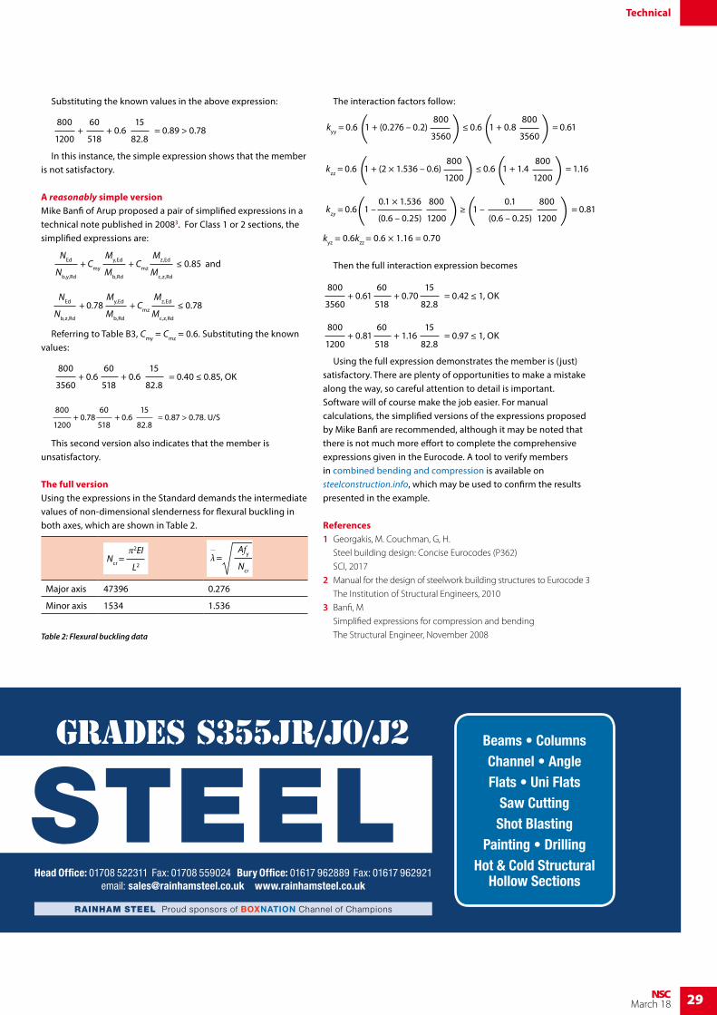
The full versionUsing the expressions in the Standard demands the intermediate values of non-dimensional slenderness for flexural buckling in both axes, which are shown in Table 2.
Table 2: Flexural buckling data
The interaction factors follow: 800
3560kyy = 0.6 1 + (0.276 – 0.2)( ) 800
3560≤ 0.6 1 + 0.8( ) = 0.61
800
1200kzz = 0.6 1 + (2 × 1.536 – 0.6)( ) 800
1200≤ 0.6 1 + 1.4( ) = 1.16
0.1 × 1.536
(0.6 – 0.25)kzy = 0.6 1 –( ) = 0.81
800
1200
0.1
(0.6 – 0.25)≥ 1 –( )800
1200
kyz = 0.6kzz = 0.6 × 1.16 = 0.70
Then the full interaction expression becomes
800
3560= 0.42 ≤ 1, OK
60
518+ 0.70
15
82.8+ 0.61
800
1200= 0.97 ≤ 1, OK
60
518+ 1.16
15
82.8+ 0.81
Using the full expression demonstrates the member is (just) satisfactory. There are plenty of opportunities to make a mistake along the way, so careful attention to detail is important. Software will of course make the job easier. For manual calculations, the simplified versions of the expressions proposed by Mike Banfi are recommended, although it may be noted that there is not much more effort to complete the comprehensive expressions given in the Eurocode. A tool to verify members in combined bending and compression is available on steelconstruction.info, which may be used to confirm the results presented in the example.
References1 Georgakis, M. Couchman, G, H.
Steel building design: Concise Eurocodes (P362)
SCI, 2017
2 Manual for the design of steelwork building structures to Eurocode 3
The Institution of Structural Engineers, 2010
3 Banfi, M
Simplified expressions for compression and bending
The Structural Engineer, November 2008
Major axis 47396 0.276
Minor axis 1534 1.536
Ncr =π2EI
L2λ =
Afy
Ncr