membrane bioreactors (mbr) - marmara Üniversitesimimoza.marmara.edu.tr/~kyapsakli/enve435/membrane...
TRANSCRIPT

MEMBRANE BIOREACTORS
(MBR)
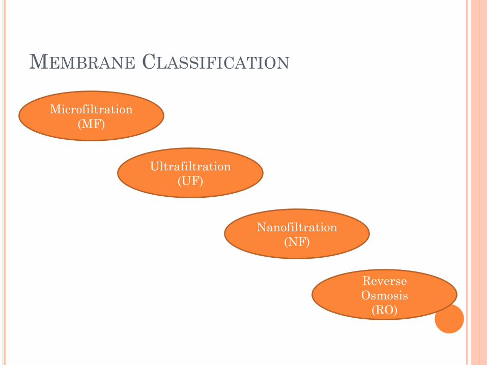
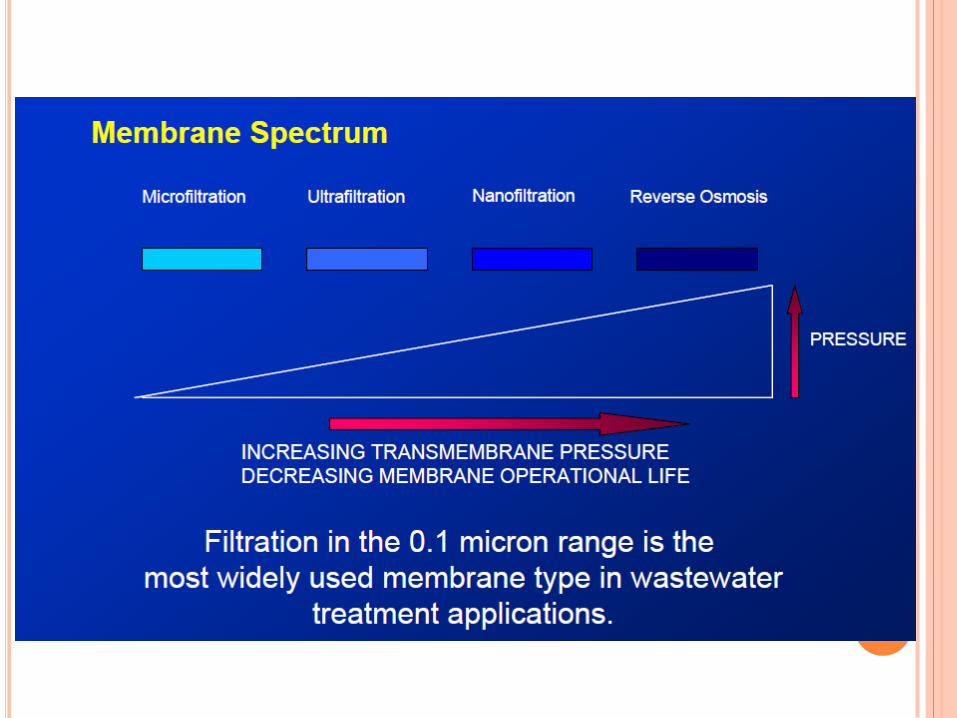
MEMBRANE CLASSIFICATION
Microfiltration
(MF)
Ultrafiltration
(UF)
Nanofiltration
(NF)
Reverse
Osmosis
(RO)
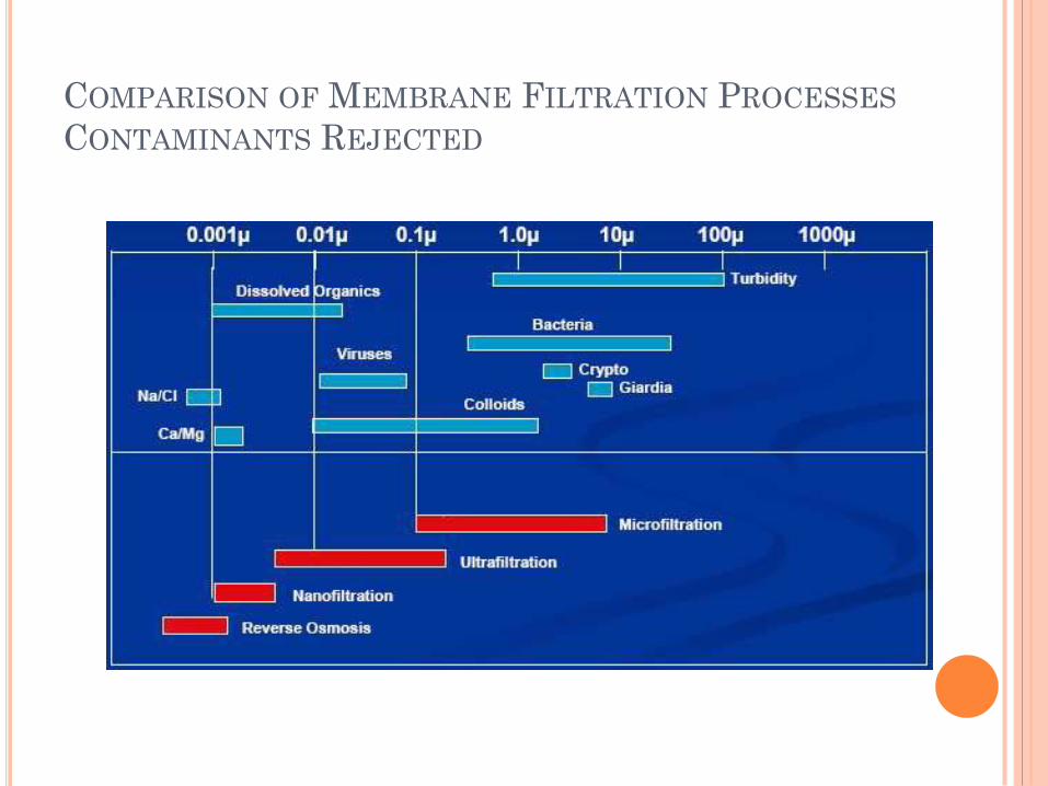
COMPARISON OF MEMBRANE FILTRATION PROCESSES
CONTAMINANTS REJECTED

GENERAL PROCESS CHARACTERISTICS
MF and UF
Low Pressure
Size Exclusion
Pathogenic bacteria
and some viruses
MBR Systems,
polishing and post
treatment
NF and RO
Higher Pressure
Size Exclusion plus
diffusion charge
Pathogenic bacteria,
viruses, dissolved
solids and ions
Secondary polishing
and post treatment

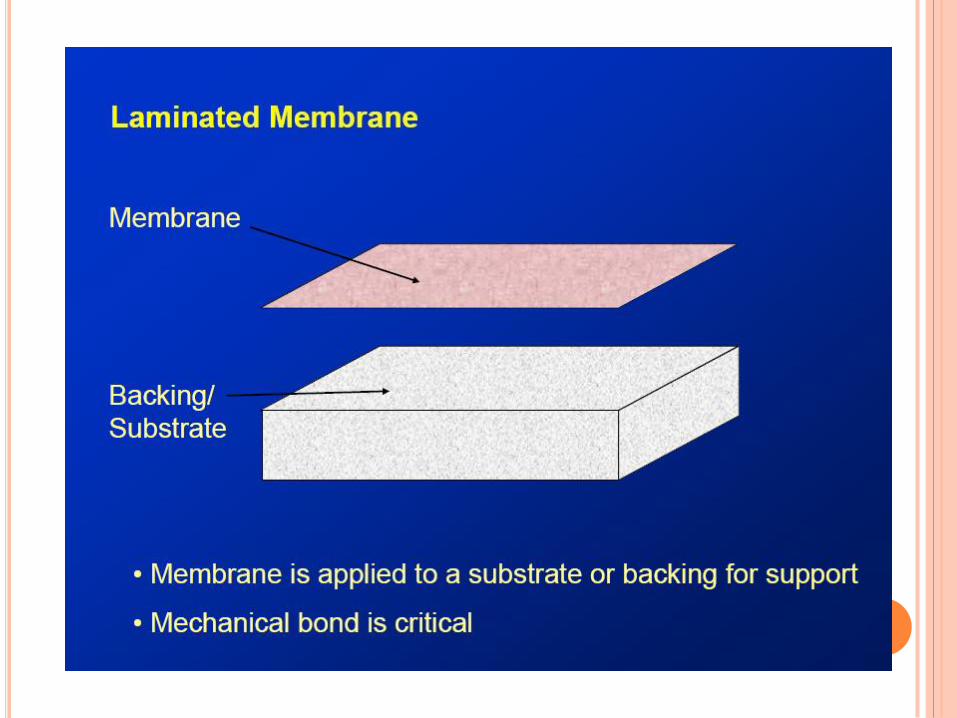
TYPICAL TYPES OF MEMBRANES
FLAT PLATE HOLLOW FIBRE


MEMBRANE BIOREACTOR


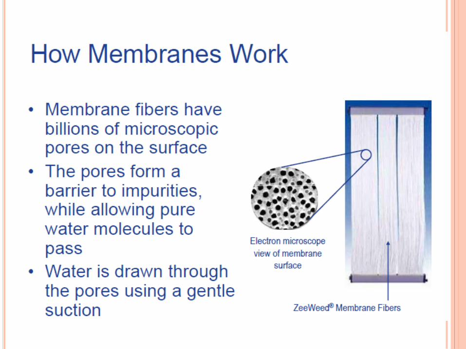
PROCESS BASICS
membrane water
suction
dis. solids
sludge floc
viruses
bacteria kinet. energy

PROCESS BASICS
SS
Deni Nitri
SS
SCT
discharge
conventional technology membrane technology
N DN
effluent UF not
Sec. Clarif.
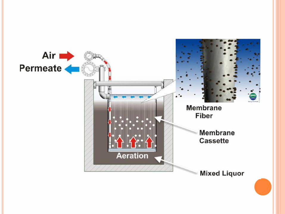
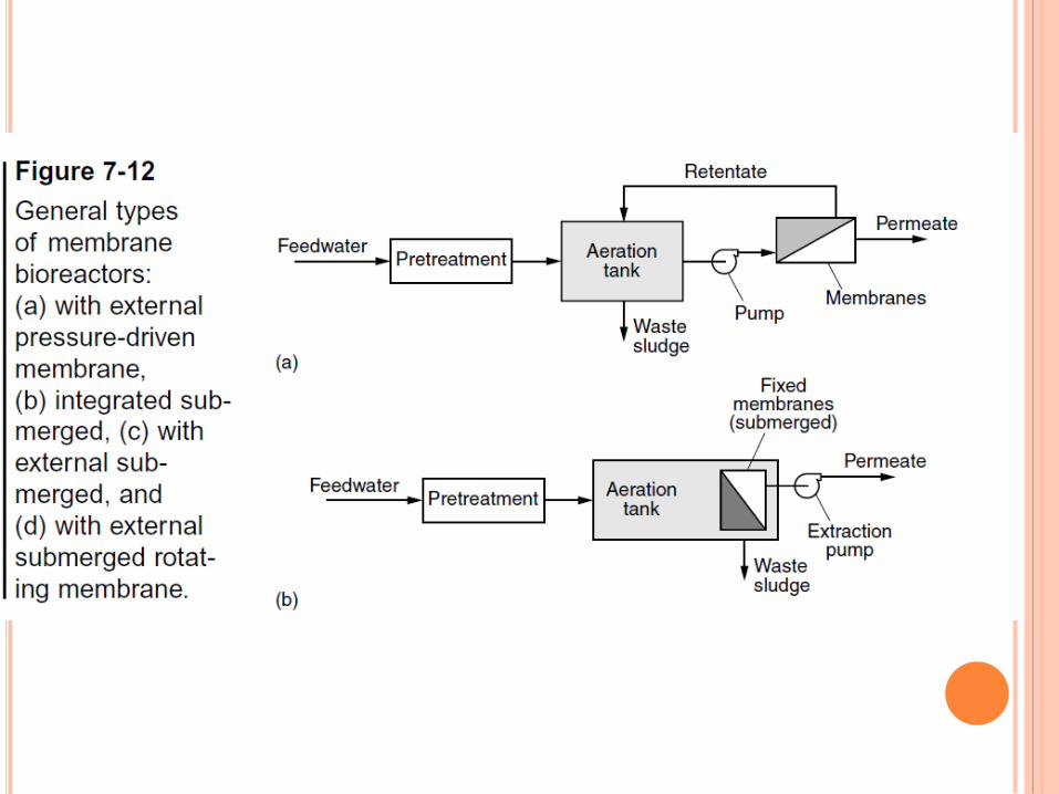
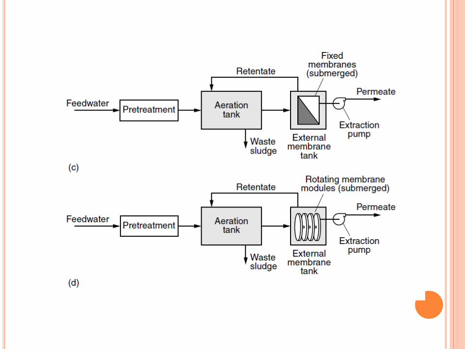
TWO CONFIGURATIONS:
External
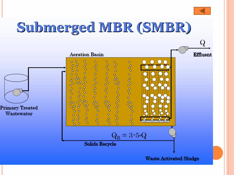
Submerged
Pressure drivencommonly in tubular form and
external
Vacuum driven


COMMON TERMS AND DEFINITIONS
COMMON TERMS AND DEFINITIONS
(CONTD)
Gross Flux
The volume of water that passes through a
membrane per unit time and per unit surface area of
the membrane. Flux is often normalized based on
temperature.
Gross Flux=Instantaneous Permeate Flow /Surface
Area
COMMON TERMS AND DEFINITIONS
(CONTD)
Net Flux
The total Permeated Flow over 24 hours divided by
the total surface area expressed in gallons per minute
per square foot.
Net Flux=Total Permeate Flow/ Surface Area
Total Surface Area
The total surface area represents the total membrane
surface area available for treatment in a membrane
system..
COMMON TERMS AND DEFINITIONS
(CONTD)
Transmembrane Pressure
The difference between average/concentrate pressure
and the permeate pressure is the driving force.
The TMP is a means to assess fouling
TMP = feed pressure – permeate pressure
Fouling
The build up of impurities on the membranes such as
colloidal materials. Fouling reduces flux through the
membrane and increase the TMP.
Micro fouling is the build up of impurities in the
membrane pores.
COMMON TERMS AND DEFINITIONS
(CONTD)
Permeability
The permeability of a membrane is the flux rate
divided by the transmembrane pressure..
P = Flux / TMP
Recovery
Recovery is the concept of restoring the hydraulic
characteristics of the membrane.
Recovery is achieved by membrane cleaning.
PROCESS VARIABLES
Temperature
Viscosity of water increases, as water temperature
decreases. Permeability and flux rate decreases
Pore size
Membrane flux rate (L/m2.hr)
MLSS increasesflux rate decreases
Qpeakdesign flux rate
Membrane life

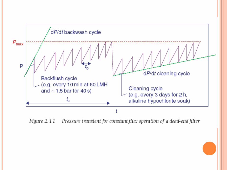
Constant TMP operation
Constant flux operationpreferred mode,
because it ensures a steady throughput.
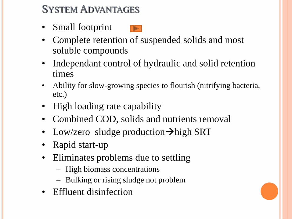
SYSTEM ADVANTAGES
• Small footprint
• Complete retention of suspended solids and most soluble compounds
• Independant control of hydraulic and solid retention times
• Ability for slow-growing species to flourish (nitrifying bacteria, etc.)
• High loading rate capability
• Combined COD, solids and nutrients removal
• Low/zero sludge productionhigh SRT
• Rapid start-up
• Eliminates problems due to settling
– High biomass concentrations
– Bulking or rising sludge not problem
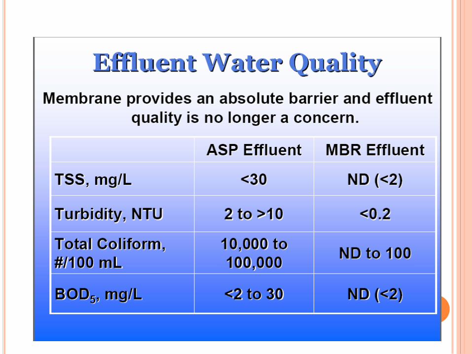
• Effluent disinfection
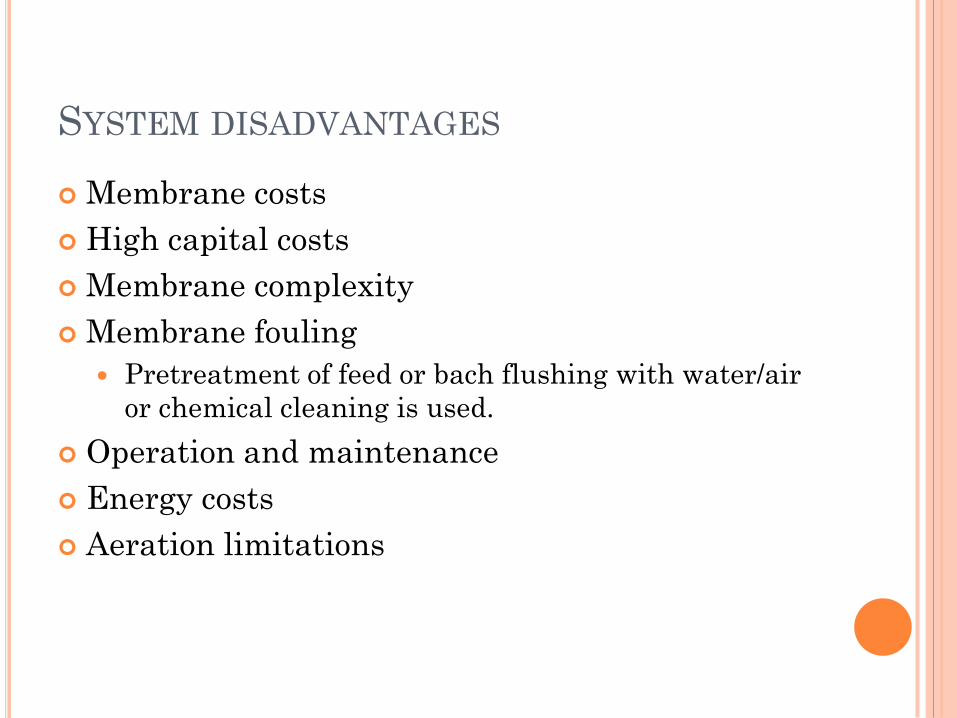
SYSTEM DISADVANTAGES
Membrane costs
High capital costs
Membrane complexity
Membrane fouling
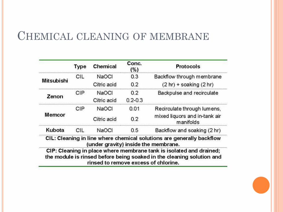
Pretreatment of feed or bach flushing with water/air
or chemical cleaning is used.
Operation and maintenance
Energy costs
Aeration limitations
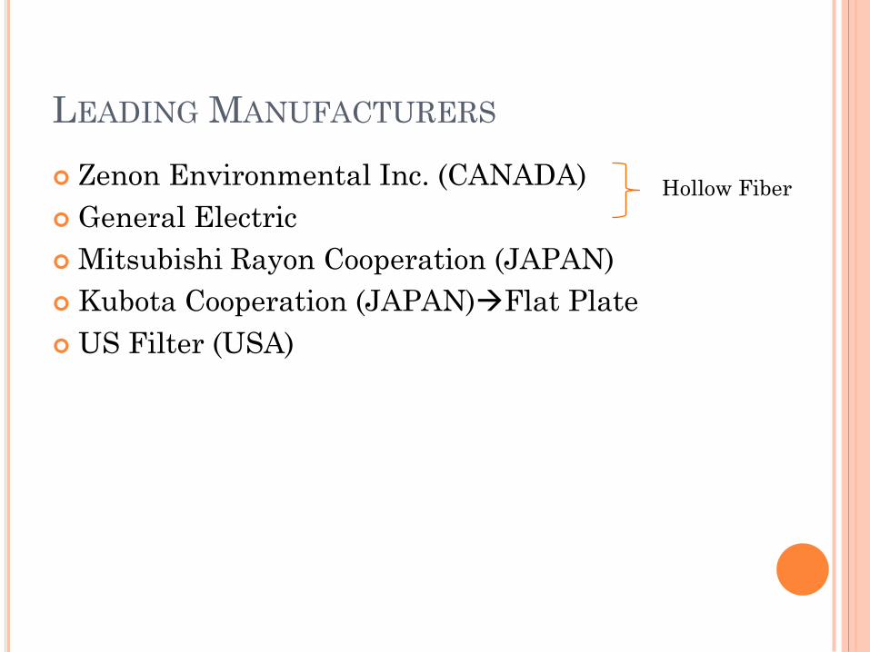
LEADING MANUFACTURERS
Zenon Environmental Inc. (CANADA)
General Electric
Mitsubishi Rayon Cooperation (JAPAN)
Kubota Cooperation (JAPAN)Flat Plate
US Filter (USA)
Hollow Fiber

Operating Conditions (Integrated System)

IMPORTANT POINTS
Pretreatment as screening and grit removal is
important
3mm screeninghair and fiber can pass, wrap
around the membrane
Many manufacturers now use 2mm screen
Best is to use 2mm, then 1mm screen
Recommended MLSS: 8000-12000 mg/L to
optimize aeration, flux and cleaning frequency
R=4, to prevent solids buildup in the membrane
area
High peaking factors equalization req’d
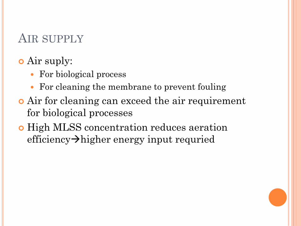
AIR SUPPLY
Air suply:
For biological process
For cleaning the membrane to prevent fouling
Air for cleaning can exceed the air requirement
for biological processes
High MLSS concentration reduces aeration
efficiencyhigher energy input requried

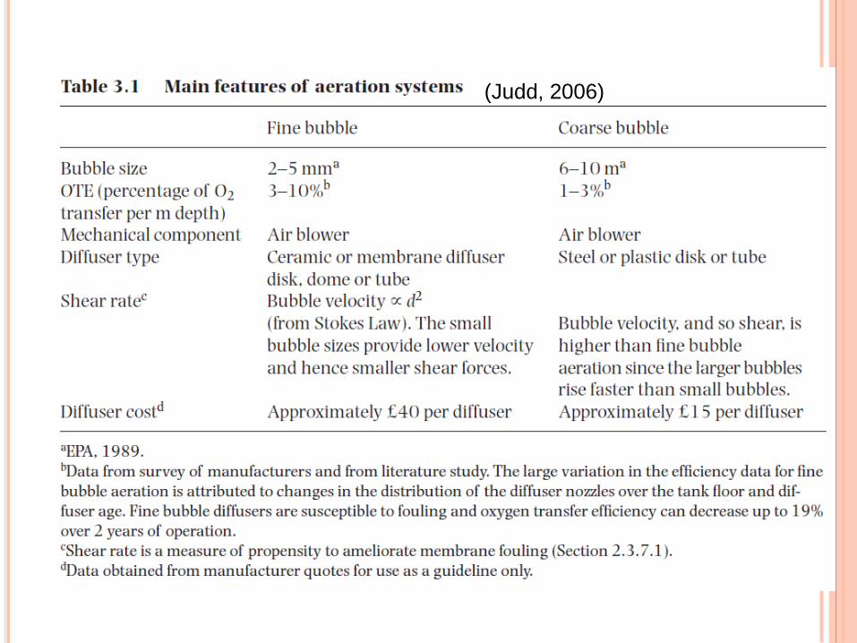
(Judd, 2006)