memograph m, rsg45 - endress+hauser · measuring system multichannel data recording system with...
TRANSCRIPT

Records, visualizes, analyzes and communicates
Application
The Advanced Data Manager Memograph M is a flexible and powerful system fororganizing process values. Thanks to its intuitive operation, the Memograph Madapts quickly and easily to the respective application. The measured process valuesare clearly presented on the display and logged safely, monitored against limitvalues, and analyzed. Via common communication protocols, the measured andcalculated values can be easily communicated to higher-level systems and individualplant modules can be interconnected.
Your benefits
• High data security: tamper-proof data storage and personalized accessauthorization with electronic signature (FDA 21 CFR 11)
• 7" TFT display for the clear presentation of measured values• Stainless steel front with touch operation: trouble-free operation in demanding
environments such as hygienic or hazardous areas• HART® input card: HART® sensors directly connected provide accurate process
values for calculation and logging• HART® gateway: time-saving direct access to HART® sensors in the field with
FieldCare using Memograph M without interrupting the measuring loop• Integrated Web server: remote access to device operation and visualization for
lower maintenance costs• WebDAV: data saved on SD card transmitted directly to a PC via HTTP without any
additional software• Future-oriented: simple device upgrade to up to 20 universal/HART® and 14
digital inputs or 12 relay outputs• System capability: supports common fieldbuses (Modbus, Profibus DP, PROFINET,
EtherNet/IP) for fast integration into different systems• Standard interfaces: can connect a USB keyboard or mouse for faster data entry
Products Solutions Services
Technical InformationMemograph M, RSG45Advanced Data Manager
TI01180R/09/EN/01.1571295935
Memograph M, RSG45
2 Endress+Hauser
Function and system design
Measuring principle Electronic acquisition, display, recording, analysis, remote transmission and archiving of analog anddigital input signals as well as calculated values.
The device is intended for installation in a panel or cabinet door. There is also the option ofoperating it in a desktop housing or field housing.
Measuring system Multichannel data recording system with multicolor TFT display (178 mm / 7" screen size), internalmemory, external memory (SD card and USB stick), galvanically isolated universal inputs (U, I, TC,RTD, pulse, frequency), HART® inputs, digital inputs, transmitter power supply, limit relays, digitaland analog outputs, communication interfaces (USB, Ethernet, RS232/485), optionally availablewith Modbus, Profibus DP or PROFINET I/O or EtherNet/IP.
An Essential Version of the Field Data Manager (FDM) software is included for SQL-supported dataanalysis at the PC.
The number of inputs available in the basic device can be individually increased using amaximum of 5 plug-in cards. The device supplies power directly to connected two-wiretransmitters. The device is configured and operated via the navigator (jog/shuttle dial) or bytouchscreen (optional), using the integrated Web server and a PC, or via an external USBkeyboard or mouse or with the FieldCare / DeviceCare configuration software. Online helpsupports the user during local operation.Ex version:• The hazardous area version (Ex version) is only available in conjunction with the stainless
steel front and touch control.• In this version, the SD card is integrated in the device and cannot be removed. The card can
be read out using the Field Data Manager (FDM) software supplied via USB or Ethernet, or byWebDAV.
Application packages /software options
In the standard version, the Advanced Data Manager has a variety of functions, including an end-to-end safety concept to meet the requirements of FDA 21 CFR Part 11. The following applicationpackages are available to help users meet the requirements of their applications and save time:
• Mathematics• Telealarm• Batch management• Wastewater + RSB (rain spillway basin)• Energy calculationThe application packages contain the standard functions and the specific package functions. Theindividual packages can be largely combined as the user requires. The application packages can alsobe activated retroactively by entering the activation code.
Standard functions
• Signal analysis: external, 1 min to 12 h, day, week, month, year• Web server• User administration compliant with FDA 21 CFR Part 11• Event log/audit trail• Process screen• Operation time counter• Text entry/comments• Change language• Time synchronization• Linearization• Access protection through release code• E-mail notification in event of alarms and limit violation• Encrypted e-mail transmission via SSL (TLS)• Operation via external USB keyboard and mouse• External USB or network printer
Mathematics
With the mathematics package, measured values of the inputs or the results of other math channelscan be linked mathematically. A formula with up to 200 characters can be created using a formulaeditor. Once entered, the user can then check the plausibility of the formula.
Memograph M, RSG45
Endress+Hauser 3
Functions:• 12 math channels• Mathematics functions via formula editor• Basic arithmetic operations, relational operators, logic operations and functions
Telealarm software
The Telealarm software facilitates user mobility, allowing users to respond to events while they areon the road. E-mails or SMS messages triggered by process alarms or other important process eventscan be sent to several recipients simultaneously or automatically forwarded to a recipient/destination. Messages can be confirmed, relays controlled remotely and current values queried bycellular phone. The Advanced Data Manager with GSM (GPRS) or Ethernet is ideal both forenvironmental applications to monitor unstaffed outstations, and for tank monitoring applications.
The Telealarm software contains the mathematics package.
Functions:• Advanced SMS/e-mail notification in the event of an alarm• Instantaneous values queried by cellular phone• Remote relay switching• Alarm confirmation by SMS
Batch software
Batch management allows users to reliably record and visualize discontinuous processes. User-definable or externally controlled analysis intervals are possible for up to four batchessimultaneously. Batches are assigned batch-specific values and the measured data, the start, end andduration of every batch, along with the current batch status, are displayed on the device and in theField Data Manager software. At the end of the batch, a batch print-out is automatically starteddirectly at the device (USB or network printer) or is printed out at a PC with the Field Data Managersoftware.
The batch software contains the mathematics package.
Functions:• Batch report for 4 batches simultaneously• USB barcode reader• Automatic batch printout• Preset counter
Wastewater + RSB (rain spillway basin)
The water/wastewater software supports operations monitoring of the water/wastewater sewagenetwork to obtain information about the quality and efficiency of the plant. The daily, weekly,monthly and yearly maximum and minimum value is determined per quantity channel. Infiltrationwater recording and the monitoring of rain spillway basins for reservoir and overflow events are alsofunctions of this software option.
The water/wastewater software contains the mathematics package and the telealarm software.
Functions:• Rain spillway basin (reservoir/overflow)• Highest and lowest values for quantities• Highest and lowest values from ¼-hourly averages• Determination of infiltration water
Energy package (water + steam)
The energy package allows users to calculate the mass and energy flow in water and steamapplications on the basis of the flow, pressure and temperature (or temperature difference) inputvariables. Furthermore, energy calculations are also possible using glycol-based refrigerant media.
By balancing the results against one another or by linking the results to other input variables (e.g.gas flow, electr. energy), users can calculate overall balances, efficiency levels etc. These values areimportant indicators for the quality of the process and form the basis for process optimization andmaintenance.
The internationally recognized standard IAPWS-IF 97 is used to calculate the thermodynamic statevariables of water and steam.
Memograph M, RSG45
4 Endress+Hauser
In the energy software, it is also possible to compensate differential pressure flow measurement("DP-Flow"). The calculation of flow based on the differential pressure method is a special form offlow measurement. Volumes or mass flow rates that are determined using the DP method requirespecific correction. By solving the calculation equations listed in the standard in an iterative manner,highly accurate results for DP flow measurements can be achieved. The measurement (orifice plate,nozzle, Venturi pipe) is performed in accordance with ISO5167. Flow measurement based on thedynamic pressure method uses the interrelation between differential pressure and flow.
The energy package contains the mathematics package.
Additional functions:• 12 math channels
(Channels 1-8: energy-specific formulas and formula editor, channels 9-12: formula editor)• Heat quantity + mass calculation for water and steam applications• Efficiency calculation
Dependability Reliability
Depending on the device version, the mean time between failures (MTBF) is between 52 years and16 years (calculated based on SN29500 standard at 40°C)
Maintainability
Battery-backed time and data memory. It is advisable to have the backup battery replaced by aservice technician after 10 years.
Real time clock (RTC)
• Automatic or manual summer time changeover• Battery buffer. It is advisable to have the backup battery replaced by a service technician after 10
years.• Drift: <10 min/year.• Time synchronization possible via SNTP or via digital input.
Standard diagnostic functions as per Namur NE 107
The diagnostic code is made up of the error category as per Namur NE 107 and the message number.
• Cable open circuit, short-circuit• Incorrect wiring• Internal device errors• Overrange/underrange detection• Ambient temperature out-of-range detection
Device error/alarm relay
One relay can be used as an alarm relay. The selected relay switches if the device detects a systemerror (e.g. hardware defect) or a malfunction (e.g. cable open circuit).
This "alarm relay" switches if the device status is "F" (Failure). If the device status is "M" (Maintenancerequired), the alarm relay does not switch.
Safety
Recorded data are saved in a tamper-proof format and can be exported and archived withmanipulation protection using the Field Data Manager software.
IT security The manufacturer only provides a warranty if the device is installed and used as described in theOperating Instructions. The device is equipped with security mechanisms to protect it against anyinadvertent changes to the device settings.
IT security measures in line with operators' security standards and designed to provide additionalprotection for the device and device data transfer must be implemented by the operators themselves.

Memograph M, RSG45
Endress+Hauser 5
Input
Measured variables Analog universal inputs
Standard version without universal inputs. Optional multifunction cards (slot 1-5) with 4 universalinputs (4/8/12/16/20) each.
You are free to choose between the following measured variables for each universal input: U, I, RTD,TC, pulse input or frequency input.
HART® inputs
Standard version without HART® inputs. Optional HART® input cards (slot 1-5) with 4 inputs(4/8/12/16/20) each.
Both the digital HART® values and the 4 to 20 mA signal can be evaluated at every input.
The 4 HART® values (PV, SV, TV, QV) of a sensor can be evaluated and the analog HART® value (PV)can be measured via the digital HART® signal. Up to 40 digital HART® values can be recorded intotal. It is possible to access the HART® sensor in the field from a PC tool (e.g. FieldCare). In this way,the sensor can be configured from the control room and the status information of the sensor can beanalyzed/displayed. The Memograph M acts as a HART® Gateway.
Access to the connected sensors is only possible if the device is connected by Ethernet.
Port 5094 must be open in the firewall.
Digital inputs
Standard version: 6 digital inputs
Optional digital card (slot 5): 8 additional digital inputs, 6 additional relays and 2 analog outputs
Math channels
12 math channels (optional). Mathematics functions can be freely edited via a formula editor.
Limit values
60 limit values (individual channel assignment)
Calculated values
The values of the universal and HART® inputs can be used to perform calculations in the mathchannels.
The results of the math channels can also be used for calculations in other math channels.
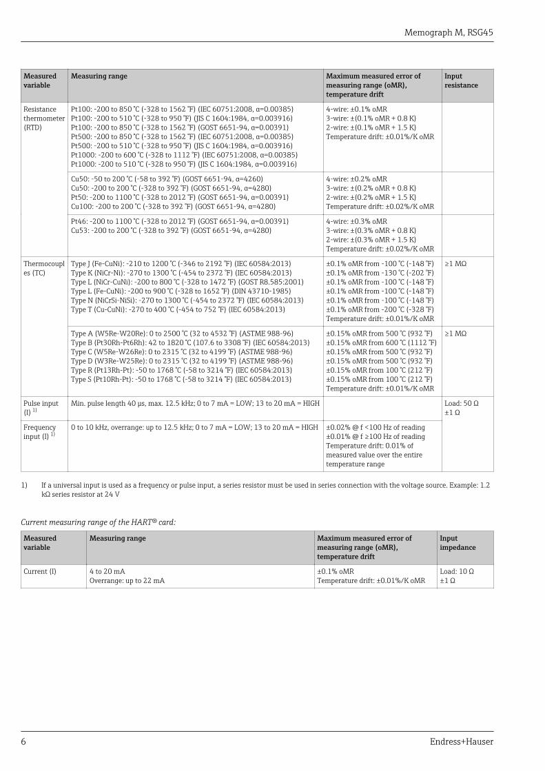
Measuring range According to IEC 60873-1: An additional display error of ±1 digit is permitted for every measuredvalue.
User-definable measuring ranges per universal input of the multifunction card:
Measuredvariable
Measuring range Maximum measured error ofmeasuring range (oMR),temperature drift
Inputresistance
Current (I) 0 to 20 mA; 0 to 20 mA quadratic0 to 5 mA4 to 20 mA; 4 to 20 mA quadratic±20 mAOverrange: up to 22 mA or -22 mA
±0.1% oMRTemperature drift: ±0.01%/K oMR
Load: 50 Ω±1 Ω
Voltage (U)>1 V
0 to 10 V; 0 to 10 V quadratic0 to 5 V1 to 5 V; 1 to 5 V quadratic±10 V±30 V
±0.1% oMRTemperature drift: ±0.01%/K oMR
≥1 MΩ
Voltage (U)≤1 V
0 to 1 V; 0 to 1 V quadratic±1 V±150 mV
±0.1% oMRTemperature drift: ±0.01%/K oMR
≥2.5 MΩ
Memograph M, RSG45
6 Endress+Hauser
Measuredvariable
Measuring range Maximum measured error ofmeasuring range (oMR),temperature drift
Inputresistance
Resistancethermometer(RTD)
Pt100: -200 to 850 °C (-328 to 1562 °F) (IEC 60751:2008, α=0.00385)Pt100: -200 to 510 °C (-328 to 950 °F) (JIS C 1604:1984, α=0.003916)Pt100: -200 to 850 °C (-328 to 1562 °F) (GOST 6651-94, α=0.00391)Pt500: -200 to 850 °C (-328 to 1562 °F) (IEC 60751:2008, α=0.00385)Pt500: -200 to 510 °C (-328 to 950 °F) (JIS C 1604:1984, α=0.003916)Pt1000: -200 to 600 °C (-328 to 1112 °F) (IEC 60751:2008, α=0.00385)Pt1000: -200 to 510 °C (-328 to 950 °F) (JIS C 1604:1984, α=0.003916)
4-wire: ±0.1% oMR3-wire: ±(0.1% oMR + 0.8 K)2-wire: ±(0.1% oMR + 1.5 K)Temperature drift: ±0.01%/K oMR
Cu50: -50 to 200 °C (-58 to 392 °F) (GOST 6651-94, α=4260)Cu50: -200 to 200 °C (-328 to 392 °F) (GOST 6651-94, α=4280)Pt50: -200 to 1100 °C (-328 to 2012 °F) (GOST 6651-94, α=0.00391)Cu100: -200 to 200 °C (-328 to 392 °F) (GOST 6651-94, α=4280)
4-wire: ±0.2% oMR3-wire: ±(0.2% oMR + 0.8 K)2-wire: ±(0.2% oMR + 1.5 K)Temperature drift: ±0.02%/K oMR
Pt46: -200 to 1100 °C (-328 to 2012 °F) (GOST 6651-94, α=0.00391)Cu53: -200 to 200 °C (-328 to 392 °F) (GOST 6651-94, α=4280)
4-wire: ±0.3% oMR3-wire: ±(0.3% oMR + 0.8 K)2-wire: ±(0.3% oMR + 1.5 K)Temperature drift: ±0.02%/K oMR
Thermocouples (TC)
Type J (Fe-CuNi): -210 to 1200 °C (-346 to 2192 °F) (IEC 60584:2013)Type K (NiCr-Ni): -270 to 1300 °C (-454 to 2372 °F) (IEC 60584:2013)Type L (NiCr-CuNi): -200 to 800 °C (-328 to 1472 °F) (GOST R8.585:2001)Type L (Fe-CuNi): -200 to 900 °C (-328 to 1652 °F) (DIN 43710-1985)Type N (NiCrSi-NiSi): -270 to 1300 °C (-454 to 2372 °F) (IEC 60584:2013)Type T (Cu-CuNi): -270 to 400 °C (-454 to 752 °F) (IEC 60584:2013)
±0.1% oMR from -100 °C (-148 °F)±0.1% oMR from -130 °C (-202 °F)±0.1% oMR from -100 °C (-148 °F)±0.1% oMR from -100 °C (-148 °F)±0.1% oMR from -100 °C (-148 °F)±0.1% oMR from -200 °C (-328 °F)Temperature drift: ±0.01%/K oMR
≥1 MΩ
Type A (W5Re-W20Re): 0 to 2500 °C (32 to 4532 °F) (ASTME 988-96)Type B (Pt30Rh-Pt6Rh): 42 to 1820 °C (107.6 to 3308 °F) (IEC 60584:2013)Type C (W5Re-W26Re): 0 to 2315 °C (32 to 4199 °F) (ASTME 988-96)Type D (W3Re-W25Re): 0 to 2315 °C (32 to 4199 °F) (ASTME 988-96)Type R (Pt13Rh-Pt): -50 to 1768 °C (-58 to 3214 °F) (IEC 60584:2013)Type S (Pt10Rh-Pt): -50 to 1768 °C (-58 to 3214 °F) (IEC 60584:2013)
±0.15% oMR from 500 °C (932 °F)±0.15% oMR from 600 °C (1112 °F)±0.15% oMR from 500 °C (932 °F)±0.15% oMR from 500 °C (932 °F)±0.15% oMR from 100 °C (212 °F)±0.15% oMR from 100 °C (212 °F)Temperature drift: ±0.01%/K oMR
≥1 MΩ
Pulse input(I) 1)
Min. pulse length 40 μs, max. 12.5 kHz; 0 to 7 mA = LOW; 13 to 20 mA = HIGH Load: 50 Ω±1 Ω
Frequencyinput (I) 1)
0 to 10 kHz, overrange: up to 12.5 kHz; 0 to 7 mA = LOW; 13 to 20 mA = HIGH ±0.02% @ f <100 Hz of reading±0.01% @ f ≥100 Hz of readingTemperature drift: 0.01% ofmeasured value over the entiretemperature range
1) If a universal input is used as a frequency or pulse input, a series resistor must be used in series connection with the voltage source. Example: 1.2kΩ series resistor at 24 V
Current measuring range of the HART® card:
Measuredvariable
Measuring range Maximum measured error ofmeasuring range (oMR),temperature drift
Inputimpedance
Current (I) 4 to 20 mAOverrange: up to 22 mA
±0.1% oMRTemperature drift: ±0.01%/K oMR
Load: 10 Ω±1 Ω
Memograph M, RSG45
Endress+Hauser 7
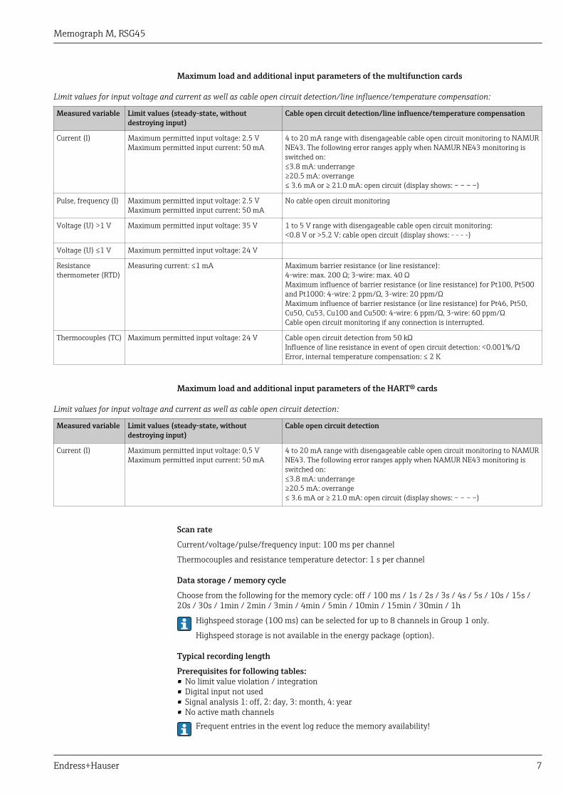
Maximum load and additional input parameters of the multifunction cards
Limit values for input voltage and current as well as cable open circuit detection/line influence/temperature compensation:
Measured variable Limit values (steady-state, withoutdestroying input)
Cable open circuit detection/line influence/temperature compensation
Current (I) Maximum permitted input voltage: 2.5 VMaximum permitted input current: 50 mA
4 to 20 mA range with disengageable cable open circuit monitoring to NAMURNE43. The following error ranges apply when NAMUR NE43 monitoring isswitched on:≤3.8 mA: underrange≥20.5 mA: overrange≤ 3.6 mA or ≥ 21.0 mA: open circuit (display shows: – – – –)
Pulse, frequency (I) Maximum permitted input voltage: 2.5 VMaximum permitted input current: 50 mA
No cable open circuit monitoring
Voltage (U) >1 V Maximum permitted input voltage: 35 V 1 to 5 V range with disengageable cable open circuit monitoring:<0.8 V or >5.2 V: cable open circuit (display shows: - - - -)
Voltage (U) ≤1 V Maximum permitted input voltage: 24 V
Resistancethermometer (RTD)
Measuring current: ≤1 mA Maximum barrier resistance (or line resistance):4-wire: max. 200 Ω; 3-wire: max. 40 ΩMaximum influence of barrier resistance (or line resistance) for Pt100, Pt500and Pt1000: 4-wire: 2 ppm/Ω, 3-wire: 20 ppm/ΩMaximum influence of barrier resistance (or line resistance) for Pt46, Pt50,Cu50, Cu53, Cu100 and Cu500: 4-wire: 6 ppm/Ω, 3-wire: 60 ppm/ΩCable open circuit monitoring if any connection is interrupted.
Thermocouples (TC) Maximum permitted input voltage: 24 V Cable open circuit detection from 50 kΩInfluence of line resistance in event of open circuit detection: <0.001%/ΩError, internal temperature compensation: ≤ 2 K
Maximum load and additional input parameters of the HART® cards
Limit values for input voltage and current as well as cable open circuit detection:
Measured variable Limit values (steady-state, withoutdestroying input)
Cable open circuit detection
Current (I) Maximum permitted input voltage: 0,5 VMaximum permitted input current: 50 mA
4 to 20 mA range with disengageable cable open circuit monitoring to NAMURNE43. The following error ranges apply when NAMUR NE43 monitoring isswitched on:≤3.8 mA: underrange≥20.5 mA: overrange≤ 3.6 mA or ≥ 21.0 mA: open circuit (display shows: – – – –)
Scan rate
Current/voltage/pulse/frequency input: 100 ms per channel
Thermocouples and resistance temperature detector: 1 s per channel
Data storage / memory cycle
Choose from the following for the memory cycle: off / 100 ms / 1s / 2s / 3s / 4s / 5s / 10s / 15s /20s / 30s / 1min / 2min / 3min / 4min / 5min / 10min / 15min / 30min / 1h
Highspeed storage (100 ms) can be selected for up to 8 channels in Group 1 only.
Highspeed storage is not available in the energy package (option).
Typical recording length
Prerequisites for following tables:• No limit value violation / integration• Digital input not used• Signal analysis 1: off, 2: day, 3: month, 4: year• No active math channels
Frequent entries in the event log reduce the memory availability!

Memograph M, RSG45
8 Endress+Hauser
Internal memory 256 MB:
Analoginputs
Channels in groups Memory cycle (weeks, days, hours)
5 min 1 min 30 s 10 s 1 s
1 1/0/0/0/0/0/0/0/0/0 1796, 6, 13 362, 5, 17 181, 4, 9 60, 4, 3 6, 0, 10
4 4/0/0/0/0/0/0/0/0/0 1319, 2, 23 267, 5, 17 134, 1, 2 44, 5, 10 4, 3, 8
8 4/4/0/0/0/0/0/0/0/0 661, 4, 3 133, 6, 21 67, 0, 16 22, 2, 17 2, 1, 16
12 4/4/4/0/0/0/0/0/0/0 441, 3, 8 89, 2, 9 44, 5, 3 14, 6, 11 1, 3, 10
20 4/4/4/4/4/0/0/0/0/0 265, 0, 15 53, 4, 7 26, 5, 21 8, 6, 16 0, 6, 6
40 4/4/4/4/4/4/4/4/4/4 132, 4, 8 26, 5, 16 13, 2, 23 4, 3, 8 0, 3, 3
External memory 1 GB SD card:
Analoginputs
Channels in groups Memory cycle (weeks, days, hours)
5 min 1 min 30 s 10 s 1 s
1 1/0/0/0/0/0/0/0/0/0 12825, 5, 20 2580, 4, 18 1291, 2, 5 430, 4, 14 43, 0, 12
4 4/0/0/0/0/0/0/0/0/0 8672, 5, 12 1749, 6, 13 875, 6, 13 292, 1, 8 29, 1, 14
8 4/4/0/0/0/0/0/0/0/0 4343, 1, 1 875, 1, 17 438, 0, 6 146, 0, 17 14, 4, 7
12 4/4/4/0/0/0/0/0/0/0 2896, 6, 13 583, 3, 21 292, 0, 6 97, 2, 20 9, 5, 4
20 4/4/4/4/4/0/0/0/0/0 1738, 6, 4 350, 1, 3 175, 1, 14 58, 3, 2 5, 5, 22
40 4/4/4/4/4/4/4/4/4/4 869, 5, 0 175, 0, 15 87, 4, 7 29, 1, 13 2, 6, 11
Converter resolution
24 bit
Totalization
The interim value, daily value, weekly value, monthly value, annual value and overall value can bedetermined (13-digit, 64 bit).
Analysis
Recording of quantity/operating time (standard function), also a min/max/median analysis withinthe set time frame.
Digital inputs Input level Logical "0" (corresponds to –3 to +5 V), activation with logical "1" (corresponds to+12 to +30 V)
Input frequency Max. 25 Hz
Pulse length Min. 20 ms
Input current Max. 2 mA
Input voltage Max. 30 V
Selectable functions
• Functions of the digital input: control input, ON/OFF event, pulse counter (13-digit, 64 bit),operation time, event+operation time, quantity from time, Profibus DP, EtherNet/IP, PROFINET.
• Functions of the control input: start recording, screensaver on, lock setup, time synchronization,change group, limit value monitoring on/off, individual LV on/off, block keyboard/navigator,start/stop analysis.Additionally for the batch software option: reset batch number, batch limit values on/off.
Memograph M, RSG45
Endress+Hauser 9
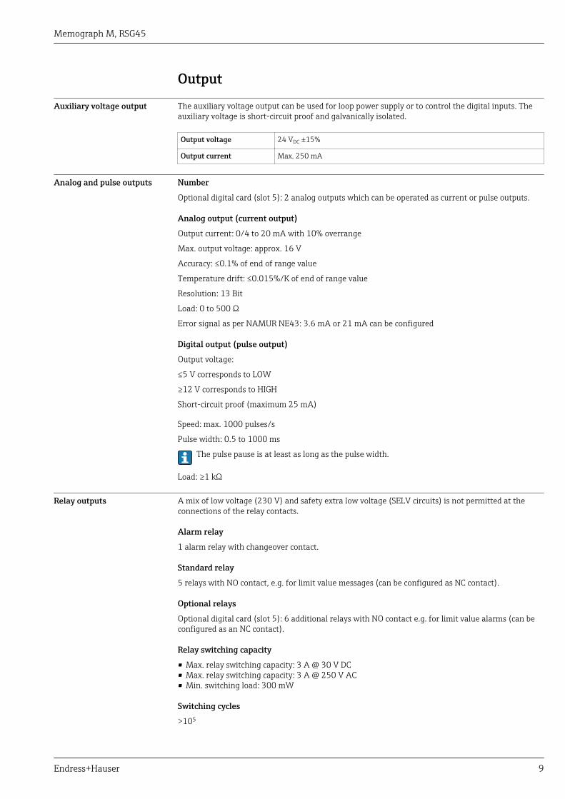
Output
Auxiliary voltage output The auxiliary voltage output can be used for loop power supply or to control the digital inputs. Theauxiliary voltage is short-circuit proof and galvanically isolated.
Output voltage 24 VDC ±15%
Output current Max. 250 mA
Analog and pulse outputs Number
Optional digital card (slot 5): 2 analog outputs which can be operated as current or pulse outputs.
Analog output (current output)
Output current: 0/4 to 20 mA with 10% overrange
Max. output voltage: approx. 16 V
Accuracy: ≤0.1% of end of range value
Temperature drift: ≤0.015%/K of end of range value
Resolution: 13 Bit
Load: 0 to 500 Ω
Error signal as per NAMUR NE43: 3.6 mA or 21 mA can be configured
Digital output (pulse output)
Output voltage:
≤5 V corresponds to LOW
≥12 V corresponds to HIGH
Short-circuit proof (maximum 25 mA)
Speed: max. 1000 pulses/s
Pulse width: 0.5 to 1000 ms
The pulse pause is at least as long as the pulse width.
Load: ≥1 kΩ
Relay outputs A mix of low voltage (230 V) and safety extra low voltage (SELV circuits) is not permitted at theconnections of the relay contacts.
Alarm relay
1 alarm relay with changeover contact.
Standard relay
5 relays with NO contact, e.g. for limit value messages (can be configured as NC contact).
Optional relays
Optional digital card (slot 5): 6 additional relays with NO contact e.g. for limit value alarms (can beconfigured as an NC contact).
Relay switching capacity
• Max. relay switching capacity: 3 A @ 30 V DC• Max. relay switching capacity: 3 A @ 250 V AC• Min. switching load: 300 mW
Switching cycles
>105
Memograph M, RSG45
10 Endress+Hauser
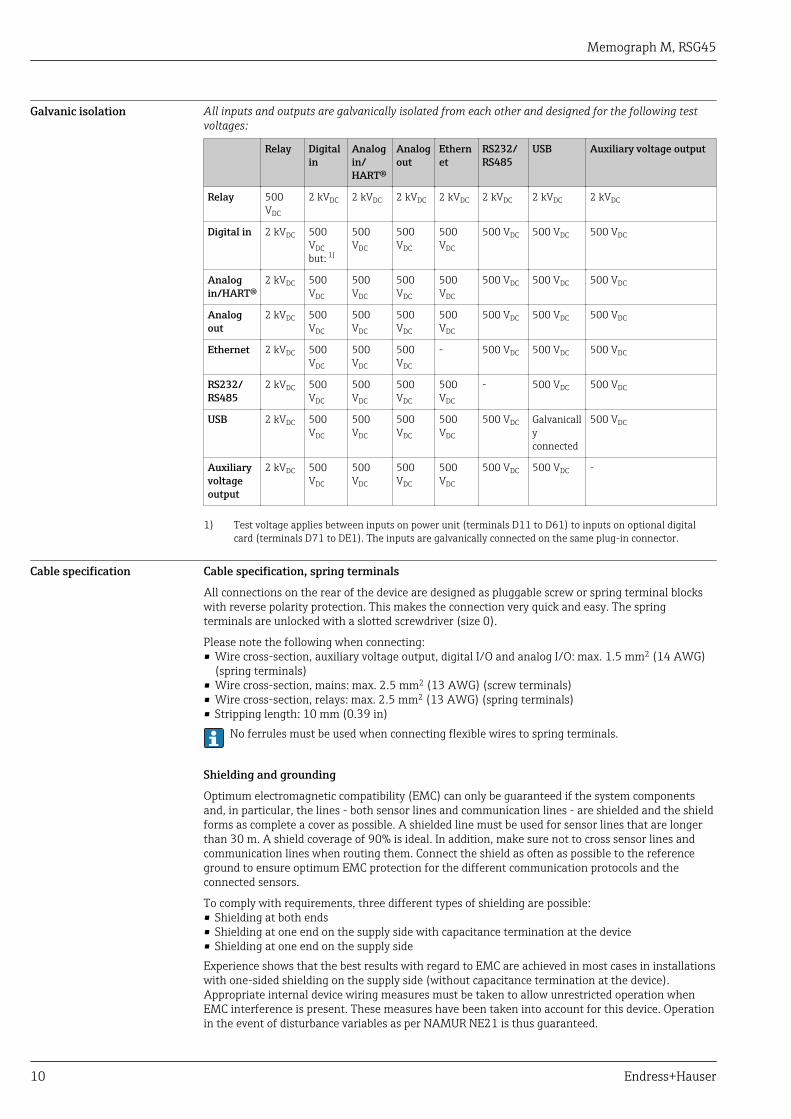
Galvanic isolation All inputs and outputs are galvanically isolated from each other and designed for the following testvoltages:
Relay Digitalin
Analogin/HART®
Analogout
Ethernet
RS232/RS485
USB Auxiliary voltage output
Relay 500VDC
2 kVDC 2 kVDC 2 kVDC 2 kVDC 2 kVDC 2 kVDC 2 kVDC
Digital in 2 kVDC 500VDCbut: 1)
500VDC
500VDC
500VDC
500 VDC 500 VDC 500 VDC
Analogin/HART®
2 kVDC 500VDC
500VDC
500VDC
500VDC
500 VDC 500 VDC 500 VDC
Analogout
2 kVDC 500VDC
500VDC
500VDC
500VDC
500 VDC 500 VDC 500 VDC
Ethernet 2 kVDC 500VDC
500VDC
500VDC
- 500 VDC 500 VDC 500 VDC
RS232/RS485
2 kVDC 500VDC
500VDC
500VDC
500VDC
- 500 VDC 500 VDC
USB 2 kVDC 500VDC
500VDC
500VDC
500VDC
500 VDC Galvanicallyconnected
500 VDC
Auxiliaryvoltageoutput
2 kVDC 500VDC
500VDC
500VDC
500VDC
500 VDC 500 VDC -
1) Test voltage applies between inputs on power unit (terminals D11 to D61) to inputs on optional digitalcard (terminals D71 to DE1). The inputs are galvanically connected on the same plug-in connector.
Cable specification Cable specification, spring terminals
All connections on the rear of the device are designed as pluggable screw or spring terminal blockswith reverse polarity protection. This makes the connection very quick and easy. The springterminals are unlocked with a slotted screwdriver (size 0).
Please note the following when connecting:• Wire cross-section, auxiliary voltage output, digital I/O and analog I/O: max. 1.5 mm2 (14 AWG)
(spring terminals)• Wire cross-section, mains: max. 2.5 mm2 (13 AWG) (screw terminals)• Wire cross-section, relays: max. 2.5 mm2 (13 AWG) (spring terminals)• Stripping length: 10 mm (0.39 in)
No ferrules must be used when connecting flexible wires to spring terminals.
Shielding and grounding
Optimum electromagnetic compatibility (EMC) can only be guaranteed if the system componentsand, in particular, the lines - both sensor lines and communication lines - are shielded and the shieldforms as complete a cover as possible. A shielded line must be used for sensor lines that are longerthan 30 m. A shield coverage of 90% is ideal. In addition, make sure not to cross sensor lines andcommunication lines when routing them. Connect the shield as often as possible to the referenceground to ensure optimum EMC protection for the different communication protocols and theconnected sensors.
To comply with requirements, three different types of shielding are possible:• Shielding at both ends• Shielding at one end on the supply side with capacitance termination at the device• Shielding at one end on the supply sideExperience shows that the best results with regard to EMC are achieved in most cases in installationswith one-sided shielding on the supply side (without capacitance termination at the device).Appropriate internal device wiring measures must be taken to allow unrestricted operation whenEMC interference is present. These measures have been taken into account for this device. Operationin the event of disturbance variables as per NAMUR NE21 is thus guaranteed.

Memograph M, RSG45
Endress+Hauser 11
Where applicable, national installation regulations and guidelines must be observed during theinstallation! Where there are large differences in potential between the individual grounding points,only one point of the shielding is connected directly with the reference ground.
If the shielding of the cable is grounded at more than one point in systems without potentialmatching, mains frequency equalizing currents can occur. These can damage the signal cable orsignificantly impact signal transmission. In such cases the shielding of the signal cable is to begrounded on one side only, i.e. it may not be connected to the ground terminal of the housing.The shield that is not connected should be insulated!
Power supply
Terminals on back of device
0
1
2
3
4
5
6
O15
O16
O25
O26
D71
D81
D91
DA
1
DB
1
DC
1
DD
1
DE
1
GN
D2
GN
D2
RA
RB
RC
RD
RE
RF
RG
RH
RI
RJ
RK
RL
Ethernet USB RS 232 / RS 485 Bus Interface
Ch
1
Ch
2
Ch
3
41
… . . … 46
Ch
4
31
… . . … 36
21
… . . … 26
11
… . . … 16
Ch
5
Ch
6
Ch
7
81
… . . … 86
Ch
8
71
… . . … 76
61
… . . … 66
51
… . . … 56
Ch
9
Ch
10
Ch
11
C1
… . . … C6
Ch
12
B1
… . . … B6
A1
… . . … A6
91
… . . … 96
G1
… . . … G6
F1
… . . … F6
E1
… . . … E6
D1
… . . … D6
L/+
N/-
PE
24VOut
R11
R12
R13
R41
R42
R51
R52
R61
R62
D11
D21
D31
D41
D51
D61
GN
D1
R21
R22
R31
R32
+
Ch
13
Ch
14
Ch
15
Ch
16
-
A0024605
1 Terminals on back of device
6 Slot 6: Power supply with relays5 Slot 5: Multifunction card or HART® card (channels 17-20) or digital card4 Slot 4: Multifunction card or HART® card (channels 13-16)3 Slot 3: Multifunction card or HART® card (channels 9-12)2 Slot 2: Multifunction card or HART® card (channels 5-8)1 Slot 1: Multifunction card or HART® card (channels 1-4)0 Slot 0: CPU card with interfaces
Supply voltage • Extra-low voltage power supply unit ±24 V AC/DC (-10% / +15%) 50/60Hz• Low voltage power supply unit 100 to 230 V AC (±10%) 50/60Hz
Overcurrent protection (rated current ≤ 10 A) must be installed for the power cable.
Power consumption • 100 to 230 V: max. 40 VA• 24 V: max. 30 VAThe power actually consumed depends on the individual operating state and the device version (LPS,USB, brightness of screen, number of channels, etc). The active power here is approx. 3 W to 25 W.
Power supply failure Battery-backed time and data memory. The device starts automatically following a power failure.
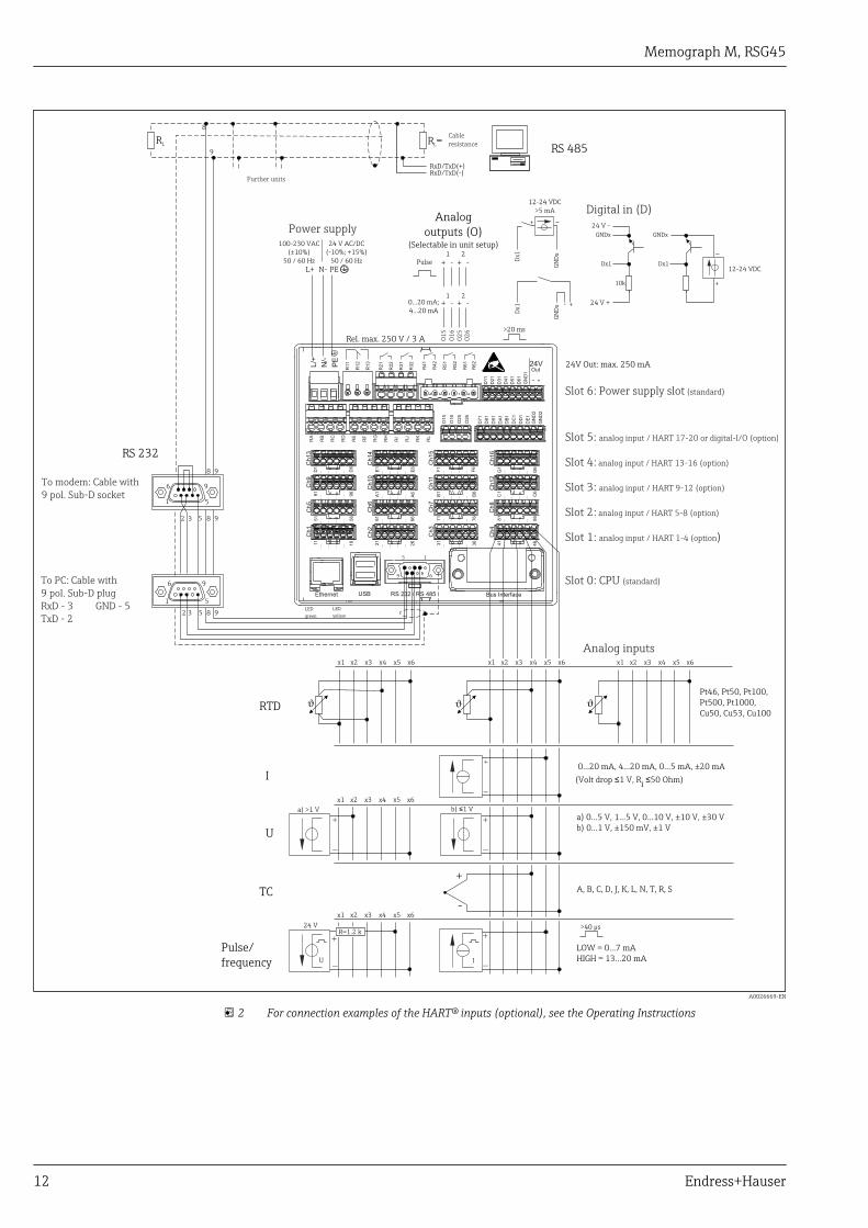
Electrical connection,terminal assignment
Circuit diagram
Memograph M, RSG45
12 Endress+Hauser
-
+
b) 1 V≤a) >1 V
Rel. max. 250 V / 3 A
a) 0...5 V, 1...5 V, 0...10 V, ±10 V, ±30 V
b) 0...1 V, ±150 mV, ±1 V
L+ N- PE
100-230 VAC
(±10%)
50 / 60 Hz
12-24 VDC
>5 mA
+
+
_
RTD
I
U
TC
0...20 mA, 4...20 mA, 0...5 mA, ±20 mA
A, B, C, D, J, K, L, N, T, R, S
+
_
12-24 VDC
24 V AC/DC
(-10%; +15%)
50 / 60 Hz
24V Out: max. 250 mA
Dx1
LOW = 0...7 mA
HIGH = 13...20 mA
15
69
>40 µs
>20 ms
RS 232
2
2
3
3
5
5
1
1
5
5
6
6
9
9
RS 485
RxD/TxD(+)
RL
RxD/TxD(-)
R =L
8
9
8 9
8 9
8 9
x2x1 x3 x4 x5 x6
x2x1 x3 x4 x5 x6
Dx1
GNDx
24 V +
Dx1
GNDx
24 V -
-
GN
Dx
Dx1
GN
Dx
10k
O1
5
O1
6
O2
5O
26
+ - + -
1 2
0...20 mA;
4...20 mA
+ - + -
1 2
Pt46, Pt50, Pt100,
Pt500, Pt1000,
Cu50, Cu53, Cu100
x2x1 x3 x4 x5 x6 x2x1 x3 x4 x5 x6
24 V
x2x1 x3 x4 x5 x6
R=1.2 k
Ethernet USB RS 232 / RS 485 Bus Interface
Ch1
Ch2
Ch3
41
… … … …
46
Ch4
31
… … … …
36
21
… … … …
26
11
… … … …
16
Ch5
Ch6
Ch7
81
… … … …
86
Ch8
71
… … … …
76
61
… … … …
66
51
… … … …
56
Ch9
Ch10
Ch11
C1
… … … …
C6
Ch12
B1
… … … …
B6
A1
… … … …
A6
91
… … … …
96
Ch13
Ch14
Ch15
G1
… … … …
G6
Ch16
F1
… … … …
F6
E1
… … … …
E6
D1
… … … …
D6
L/+
N/-
PE
24VOut
O1
5
O1
6
O2
5
O2
6
D7
1
D8
1
D9
1
DA
1
DB
1
DC
1
DD
1
DE
1
GN
D2
GN
D2
R11
R1
2
R1
3
R4
1
R4
2
R5
1
R5
2
R6
1
R6
2
D11
D2
1
D3
1
D4
1
D5
1
D6
1
GN
D1
+
R2
1
R2
2
R3
1
R3
2
-
RA
RB
RC
RD
RE
RF
RG
RH
RI
RJ
RK
RL
+
-
+
-
+
-
+
-
+
-U I
(Volt drop 1 V, Ri
50 Ohm)≤ ≤
Further units
Cable
resistance
Power supply
Digital in (D)
To PC: Cable with
9 pol. Sub-D plug
RxD - 3 GND - 5
TxD - 2
To modem: Cable with
9 pol. Sub-D socket
Analog inputs
LED
yellow
LED
green
Pulse/
frequency
Slot 6: Power supply slot
Slot 5:
Slot 4:
Slot 3:
Slot 2:
Slot 1: )
Slot 0: CPU
(standard)
1-4 (option
analog input 17-20 or digital-I/O (option)
analog input 13-16 (option)
analog input 9-12 (option)
analog input 5-8 (option)
analog input
(standard)
/ HART
/ HART
/ HART
/ HART
/ HART
Analog
outputs (O)(Selectable in unit setup)
Pulse
A0026669-EN
2 For connection examples of the HART® inputs (optional), see the Operating Instructions
Memograph M, RSG45
Endress+Hauser 13
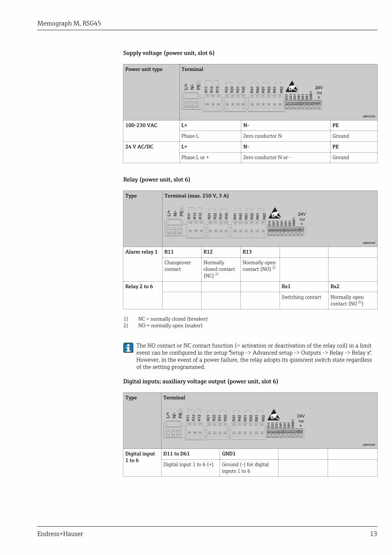
Supply voltage (power unit, slot 6)
Power unit type Terminal
A0019103
100-230 VAC L+ N- PE
Phase L Zero conductor N Ground
24 V AC/DC L+ N- PE
Phase L or + Zero conductor N or - Ground
Relay (power unit, slot 6)
Type Terminal (max. 250 V, 3 A)
A0019103
Alarm relay 1 R11 R12 R13
Changeovercontact
Normallyclosed contact(NC) 1)
Normally opencontact (NO) 2)
Relay 2 to 6 Rx1 Rx2
Switching contact Normally opencontact (NO 2))
1) NC = normally closed (breaker)2) NO = normally open (maker)
The NO contact or NC contact function (= activation or deactivation of the relay coil) in a limitevent can be configured in the setup "Setup -> Advanced setup -> Outputs -> Relay -> Relay x".However, in the event of a power failure, the relay adopts its quiescent switch state regardlessof the setting programmed.
Digital inputs; auxiliary voltage output (power unit, slot 6)
Type Terminal
A0019103
Digital input1 to 6
D11 to D61 GND1
Digital input 1 to 6 (+) Ground (-) for digitalinputs 1 to 6

Memograph M, RSG45
14 Endress+Hauser
Type Terminal
A0019103
Auxiliaryvoltageoutput, notstabilized,max. 250 mA
24V Out - 24V Out +
- Ground + 24V (±15%)
If the auxiliary voltage is to be used for the digital inputs, the 24 V out - terminal of theauxiliary voltage output must be connected with the GND1 terminal.
Analog inputs (slot 1-5)
The first digit (x) of the two-digit terminal number corresponds to the associated channel:
Type Terminal
Ch
x
x1
x2
x3
x4
x5
x6
A0019303
x1 x2 x3 x4 x5 x6
Current/pulse/frequencyinput 1)
(+) (-)
Voltage > 1V (+) (-)
Voltage ≤ 1V (+) (-)
Resistance thermometerRTD (2-wire)
(A) (B)
Resistance thermometerRTD (3-wire)
(A) b (sense) (B)
Resistance thermometerRTD (4-wire)
(A) a (sense) b (sense) (B)
Thermocouples TC (+) (-)
1) If a universal input is used as a frequency or pulse input, a series resistor must be used in series connectionwith the voltage source. Example: 1.2 kΩ series resistor at 24 V
Memograph M, RSG45
Endress+Hauser 15
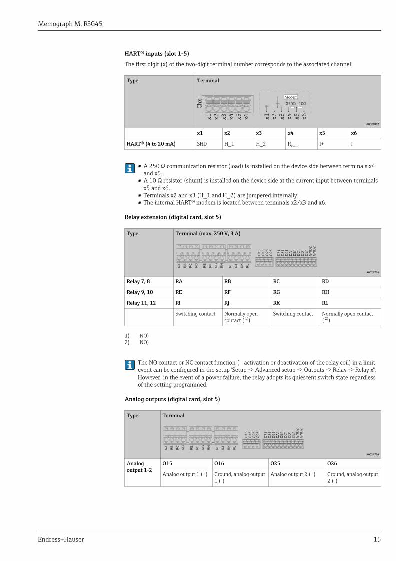
HART® inputs (slot 1-5)
The first digit (x) of the two-digit terminal number corresponds to the associated channel:
Type Terminal
Ch
x
x1 x2 x3 x4 x5 x6
250Ω 10Ω
x1 x2 x3 x4 x5 x6
Modem
A0024862
x1 x2 x3 x4 x5 x6
HART® (4 to 20 mA) SHD H_1 H_2 Rcom I+ I-
• A 250 Ω communication resistor (load) is installed on the device side between terminals x4and x5.
• A 10 Ω resistor (shunt) is installed on the device side at the current input between terminalsx5 and x6.
• Terminals x2 and x3 (H_1 and H_2) are jumpered internally.• The internal HART® modem is located between terminals x2/x3 and x6.
Relay extension (digital card, slot 5)
Type Terminal (max. 250 V, 3 A)
O1
5
O1
6
O2
5
O2
6
D7
1
D8
1
D9
1
DA
1
DB
1
DC
1
DD
1
DE
1
GN
D2
GN
D2
RA
RB
RC
RD
RE
RF
RG
RH
RI
RJ
RK
RL
A0024736
Relay 7, 8 RA RB RC RD
Relay 9, 10 RE RF RG RH
Relay 11, 12 RI RJ RK RL
Switching contact Normally opencontact ( 1))
Switching contact Normally open contact( 2))
1) NO)2) NO)
The NO contact or NC contact function (= activation or deactivation of the relay coil) in a limitevent can be configured in the setup "Setup -> Advanced setup -> Outputs -> Relay -> Relay x".However, in the event of a power failure, the relay adopts its quiescent switch state regardlessof the setting programmed.
Analog outputs (digital card, slot 5)
Type Terminal
O1
5
O1
6
O2
5
O2
6
D7
1
D8
1
D9
1
DA
1
DB
1
DC
1
DD
1
DE
1
GN
D2
GN
D2
RA
RB
RC
RD
RE
RF
RG
RH
RI
RJ
RK
RL
A0024736
Analogoutput 1-2
O15 O16 O25 O26
Analog output 1 (+) Ground, analog output1 (-)
Analog output 2 (+) Ground, analog output2 (-)

Memograph M, RSG45
16 Endress+Hauser
Extension of digital inputs (digital card, slot 5)
Type Terminal
O1
5
O1
6
O2
5
O2
6
D7
1
D8
1
D9
1
DA
1
DB
1
DC
1
DD
1
DE
1
GN
D2
GN
D2
RA
RB
RC
RD
RE
RF
RG
RH
RI
RJ
RK
RL
A0024736
Digital input 7 to14
D71 to DE1 GND2 GND2
Digital input 7 to 14 (+) Ground (-) for digital inputs 7to 14
Ground (-) for digital inputs 7to 14
If the auxiliary voltage is to be used for the digital inputs, the 24 V out - terminal of theauxiliary voltage output (power unit, slot 6) must be connected with the GND2 terminal.
Connector • Panel-mounted device: connected to mains via plug-in screw terminals with reverse polarityprotection
• Desktop version (option): connected to mains via IEC connector
Overvoltage protection To avoid high-energy transients on long signal cables, connect a suitable surge arrester upstream(e.g. E+H HAW562).
Connection data interface,communication
USB interfaces:
1 x USB port type A (host) on the front of device (only for version with navigator and front interfaces)
A USB 2.0 port is available on a shielded USB A socket at the front of the device. A USB stick as amemory medium, for example, can be connected to this port, as can an external keyboard/mouse fordevice operation, a USB hub, a barcode reader or a printer (PCL5c or higher).
1 x USB port type B (function) on the front of device (only for version with navigator and frontinterfaces)
A USB 2.0 port is available on a shielded USB B socket at the front of the device. This can be used toconnect the device for communication with a laptop, for example.
2 x USB port type A (host) on the rear of the device (standard)
Two USB 2.0 ports are available on shielded USB A sockets on the rear of the device. A USB stick as amemory medium, for example, can be connected to these ports, as can an external keyboard/mousefor device operation, a USB hub, a barcode reader or a printer (PCL5c or higher).
• USB 2.0 is compatible with USB 1.1 or USB 3.0, i.e. communication is possible.• The assignment of the USB interfaces complies with the standard such that shielded standard
cables with a maximum length of 3 meters (9.8 ft) can be used here.• The USB devices are detected by the "plug-and-play" function. If several devices of the same
type are connected, only the USB device that was connected first is available.• A maximum of 8 external USB devices (incl. USB hub) can be connected if they do not exceed
the maximum load of 500 mA. If overloaded, the corresponding USB devices areautomatically disabled. An active USB hub can be used for higher power ratings.
Reference list for USB printers:HP Color LaserJet CP1515n, HP Color LaserJet Pro CP1525n, ECOSYS P6021cdn
The printer must support PCL5c (or higher). GDI printers are not supported!
Reference list for USB barcode readers:Datalogic Gryphon D230; Metrologic MS5100 Eclipse Series; Symbol LS2208, Datalogic Quickscan 1,Godex GS220, Honeywell Voyager 9590
Ethernet interface (standard):
Ethernet interface on back, 10/100 Base-T, plug type RJ45. The Ethernet interface can be used tointegrate the device via a hub or switch into a PC network (TCP/ IP Ethernet). A standard patch cable(e.g. CAT5E) can be used for the connection. Using DHCP, the device can be fully integrated into anexisting network without the need for additional configuration. The device can be accessed from

Memograph M, RSG45
Endress+Hauser 17
every PC in the network. Normally only the automatic assignment of the IP address must beconfigured at the client. When the device is started, it can automatically retrieve the IP address,subnet mask and gateway from a DHCP server. If a DHCP is not used (depending on the specificnetwork) these settings must be made directly in the device. Two Ethernet function LEDs are locatedon the rear of the device.
The following functions are implemented:• Data communication with PC software (analysis software, configuration software, OPC server)• Web server• WebDAV (Web-based Distributed Authoring and Versioning) is an open standard for the
provisioning of files via the HTTP protocol. The data saved on the device's SD card can be read outusing a PC. At the PC, users can choose to use a Web browser or an individual WebDAV client toread out the data.
Ethernet Modbus TCP master (option):
As a Modbus master, the device can interrogate other Modbus slaves via Ethernet. The Modbus TCPmaster can be operated in parallel with the Profibus DP slave, Modbus RTU / TCP slave or PROFINETI/O Device.
Up to 40 analog inputs can be transmitted via Modbus and stored in the device.
Ethernet Modbus TCP slave (option):
Connection to SCADA systems (Modbus master).
Up to 40 analog inputs and 20 (14 real + 6 virtual) digital inputs can be transmitted via Modbus andstored in the device.
Serial RS232/RS485 interface:
A combined RS232/RS485 connection is available on a shielded SUB D9 socket at the rear of thedevice. This can be used for data transfer and to connect a modem. For communication via modem,we recommend an industrial modem with a watchdog function.
• The following baud rates are supported: 9600, 19200, 38400, 57600, 115200• Max. cable length with a shielded cable: 2 m (6.6 ft) (RS232), or. 1000 m (3281 ft) (RS485)
Only one interface can be used at any one time (RS232 or RS485).
Modbus RTU master (option):
As a Modbus master, the device can interrogate other Modbus slaves via RS485. The Modbus RTUmaster can be operated in parallel with the Profibus-DP slave, PROFINET I/O Device or Modbus TCPslave.
Up to 40 analog inputs can be transmitted via Modbus and stored in the device.
Modbus RTU slave (option):
The device can be interrogated as a Modbus slave by another Modbus master via RS485.
Up to 40 analog inputs and 20 (14 real + 6 virtual) digital inputs can be transmitted via Modbus andstored in the device.
A Modbus RTU master and RTU slave cannot be operated in parallel.
Remote interrogation with analog or GSM/GPRS wireless modem:
Analog modem:An analog modem (e.g. Devolo or WESTERMO), which is connected to the RS232 interface with aspecial modem cable (see Accessories → 26), is recommended for industry.GSM/GPRS wireless modem:A GSM/GPRS wireless modem (e.g. Cinterion, INSYS or WESTERMO, incl. antenna and power unit)which is connected to the RS232 interface with a special modem cable (see Accessories → 26),is recommended for industry.Important: The wireless modem needs a SIM card and data transfer subscription. In addition, it mustbe possible to deactivate the PIN prompt.

Memograph M, RSG45
18 Endress+Hauser
AnyBus® interface (CPU card, slot 0, optional)
PROFIBUS–DP slave:
The device can be integrated into a fieldbus system as per the PROFIBUS–DP standard by means ofthe PROFIBUS-DP interface. Up to 40 analog inputs and 20 (14 real + 6 virtual) digital inputs can betransmitted via PROFIBUS-DP and stored in the device. Bidirectional communication with cyclic datatransfer is possible. Connection via Sub-D socket.
Baudrate: maximum 12 Mbit/s
EtherNet/IP I/O adapter (slave):
Up to 40 analog inputs and 20 (14 real + 6 virtual) digital inputs can be transmitted via EtherNet/IPand stored in the device. The built-in module corresponds to I/O server category (Level 2). It has anintegrated 2-port switch, thereby supporting EtherNet/IP communication with line or ring topology.Connection via 2 RJ45 standard sockets.
PROFINET I/O device:
Up to 40 analog inputs and 20 (14 real + 6 virtual) digital inputs can be transmitted via PROFINETIO and stored in the device. The 2-port module for PROFINET IO meets compliance class B. Theintegrated switch enables communication in line or ring topologies without an additional externalswitch. Connection via 2 RJ45 standard sockets.
Performance characteristics
Response time Input Output Time [ms]
Current, voltage, pulse Relays, OC, analog output ≤ 550
RTD Relays, OC, analog output ≤ 1150
TC 1) Relays, OC, analog output ≤ 1550
Cable open circuit detection, current input Relays, OC, analog output ≤ 1150
Cable open circuit detection, RTD, TC Relays, OC, analog output ≤ 5000
Digital input Relays, OC, analog output ≤ 350
HART® input Relays, OC, analog output Non-deterministic
1) If internal measuring point temperature compensation is used, otherwise values as for voltage
Reference operatingconditions
Reference temperature 25 °C (77 °F) ±5 K
Warm-up period 120 min.
Humidity 20 to 60 % rel. humidity
Hysteresis Can be configured for limit values in the setup
Long-term drift As per IEC 61298-2: max. ±0.1%/year (of measuring range)
Installation
Panel mounting: mountinglocation and installationdimensions
The device is designed for use in a panel.
The device must be installed in a pressurized enclosure system for operation in the hazardousarea. To ensure safe installation, it is essential to follow the installation instructions for thecabinet and the installation instructions in the Ex-related Safety Instructions (XA).

Memograph M, RSG45
Endress+Hauser 19
27(1.06)
14
9.2
(5
.87
)
195.2 (7.69)
37.1
141.2 (5.56)
158.5 (6.24)
(1.46)
15
0 (
5.9
1)
196 (7.72) 31.4 (1.24)141.2 (5.56)
158.5 (6.24)
138(5.43
)
+1
+0.04
138(5.43
)
+1
+0.04
A
B
C
138
(5.43)
13
8(5
.43
)
70
16
2 (
6.3
8)
(2.76)
24
(0
.94
)
208 (8.19)
A0024610
3 Panel mounting and dimensions in mm (in).
A Version with navigator and front interfacesB Version with stainless steel front and touchscreenC Grid dimensions of panel cutouts for multiple devices
Installation dimensions
• Installation depth (excluding terminal cover): approx. 159 mm (6.26 in) for device incl. terminalsand fastening clips.
• Installation depth including terminal cover (option): approx.198 mm (7.8 in)• Panel cutout: 138 to 139 mm (5.43 to 5.47 in) x 138 to 139 mm (5.43 to 5.47 in)• Panel thickness: 2 to 40 mm (0.08 to 1.58 in)• viewing angle range: 50˚ in all directions from the display central axis• A minimum distance of 12 mm (0.47 in) between the devices must be observed if aligning the
devices vertically above one another or horizontally beside one another.• The grid dimension of the panel cutouts for multiple devices must be at least 208 mm (8.19 in)
horizontally and at least 162 mm (6.38 in) vertically (tolerance not considered).• Securing to DIN 43 834
Field housing assembly anddesign (optional)
As an option, the device can be ordered ready-mounted in a field housing with IP65.
Dimensions (B x H x D) approx.: 320 mm (12.6 in) x 320 mm (12.6 in) x 254 mm (10 in)

Memograph M, RSG45
20 Endress+Hauser
Desktop housing assemblyand design (optional)
As an option, the device can be ordered ready-mounted in a desktop housing.
Dimensions (B x H x D) approx.: 293 mm (11.5 in) x 188 mm (7.4 in) x 213 mm (8.39 in)(dimensions with bracket, feet and installed device)
Environment
Ambient temperature range –10 to +50 °C (14 to 122 °F)
Storage temperature –20 to +60 °C (–4 to +140 °F)
Humidity 5 to 85 %, not condensating
Climate class To IEC 60654-1: Class B2
Electrical safety Class I equipment, overvoltage category II
Pollution level 2
Altitude < 2 000 m (6 561 ft) above MSL
Degree of protection Front IP65 / NEMA 4 (not assessed by UL)
Rear IP20
Electromagneticcompatibility
• Interference immunity: as per IEC 61326 series (industrial environment) / NAMUR NE 21Maximum measured error <1% of measuring range
• Interference emissions: as per IEC 61326-1 Class A
Mechanical construction
Design, dimensions Information about design and dimensions → 18
Weight • Panel-mounted device with navigator and front interfaces (with maximum configuration): approx.2.7 kg (5.9 lbs)
• Panel-mounted device with stainless steel front and touchscreen (with maximum configuration):approx. 3.2 kg (7 lbs)
• Desktop housing (excluding device): approx. 2.3 kg (5 lbs)• Field housing (excluding device): approx. 4 kg (8.8 lbs)
Materials Version with navigator and front interfaces
Front frame Zinc die cast GD-Z410, powder-coated
Display glass Transparent Makrolon® plastic (FR clear 099) UL94-V2
Flap; jog/shuttle dial ("Navigator") Plastic ABS UL94-V2
Membrane keypad Polyester membrane PC-ABS UL94-V2
Intermediate frame (front towards control panel) Plastic PA6-GF20 UL94-V2
Seal towards panel wall; seal in flap; seal towardsnavigator
Rubber EPDM 70 Shore A
Casing; rear panel Galvanized sheet steel St 12 ZE

Memograph M, RSG45
Endress+Hauser 21
Version with stainless steel front and touchscreen
Front frame AISI 316L
Display glass 6 mm single-pane safety glass (soda-lime glass)
Intermediate frame (front towards control panel) Plastic PA6-GF20 UL94-V2
Seal towards control panel wall Rubber EPDM 70 Shore A
Window seal between front frame and glass Rubber EPDM 60 Shore A
Casing; rear panel Galvanized sheet steel St 12 ZE
Designation Short form Properties
AISI 316L (corresponds to1.4404 or 1.4435)
X2CrNiMo17-13-2,X2CrNiMo18-14-3
Austenitic, stainless steelHigh corrosion resistance in general
All materials are silicone-free.
Materials of desktop housing
• Housing half-panels: sheet steel, electrolytically plated (powder-coated)• Side sections: aluminum extruded section (powder-coated)• Section ends: colored polyamide• Feet: colored polyamide, fiber-glass reinforced
Field housing materials
• Housing (front frame, door, base frame, side parts): thermoplastic polycarbonate PC• Front panel and wall mounting: chrome-nickel stainless steel 1.4301 V2A
Display and operating elements
Operating concept The device can be operated directly onsite, or via remote configuration with the PC via interfaces andoperating tools (Web server, configuration software).
Web serverA Web server is integrated into the device. The Web server offers the following range of functions:• Easy configuration without additional installed software• Instantaneous value display and diagnostics information• Display of current measured value curves via Web browser (remote control)• Loading/saving of device configuration• Device firmware update• Printout of device configurationIntegrated operating instructionsThe device's simple control system enables you to perform commissioning for many applicationswithout the need for hardcopy operating instructions. The device has an integrated help functionand displays operating instructions directly on screen.
Local operation Display elements
Type
Wide-screen TFT color graphic display (optionally with touch control)
Size (diagonal screen measurement)
178 mm (7")
Resolution
Wide VGA 384,000 pixels (800 x 480 pixels)
Memograph M, RSG45
22 Endress+Hauser
Backlight
50,000 h half value time (= half brightness)
Number of colors
262,000 viewable colors, 256 colors used
Viewing angle
Max. viewing angle range: 50˚ in all directions from the display central axis
Screen display
• Users can choose between black or white for the background color• Active channels can be assigned to up to 10 groups. To clearly identify these groups, they can be
assigned a name, such as "temp. boiler 1" or "daily averages".• Scales linear or logarithmic• Measured value history: quick retrieval of historic data with zoom function• Preformatted display formats, such as horizontal or vertical curves, instrument display, circular
chart, process screen, bargraph or digital display.
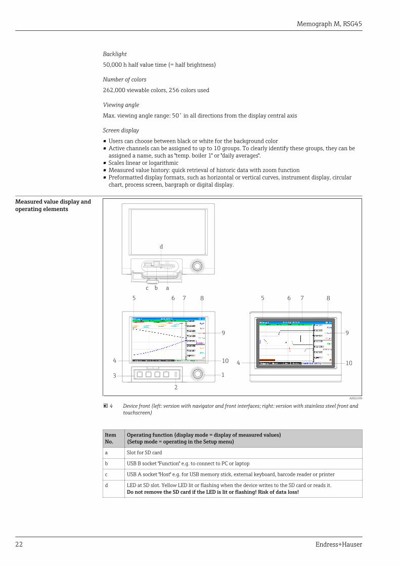
Measured value display andoperating elements
5
9
8
4
3
d
c b a
1
2
6 7
10
5
9
8
4
6 7
10
A0024709
4 Device front (left: version with navigator and front interfaces; right: version with stainless steel front andtouchscreen)
ItemNo.
Operating function (display mode = display of measured values)(Setup mode = operating in the Setup menu)
a Slot for SD card
b USB B socket "Function" e.g. to connect to PC or laptop
c USB A socket "Host" e.g. for USB memory stick, external keyboard, barcode reader or printer
d LED at SD slot. Yellow LED lit or flashing when the device writes to the SD card or reads it.Do not remove the SD card if the LED is lit or flashing! Risk of data loss!

Memograph M, RSG45
Endress+Hauser 23
ItemNo.
Operating function (display mode = display of measured values)(Setup mode = operating in the Setup menu)
1 "Navigator": jog/shuttle dial for operating with additional press/hold function.In display mode: turn the dial to switch between the various signal groups. Press the dial to display themain menu.In setup mode or in a selection menu: turn the dial anticlockwise to move the bar or the cursorupwards or counterclockwise, changes the parameter. Turning clockwise moves the bar or cursordown or clockwise, changes parameter. Press = select highlighted function, start parameter change(ENTER key).
2 Functions of LED indicators (according to NAMUR NE44:)• Green LED (top) lit: power supply OK• Red LED (bottom) flashing: maintenance required, caused by external factor (e.g. cable open circuit
etc.), or a message/notification requiring acknowledgment is pending, calibration is running.
3 Variable "soft keys", keys 1 to 4 (from left to right)
4 Function indicator of the "soft keys"
5 In display mode: current group name, type of analysis;In setup mode: name of the current operating item (dialog title)
6 In display mode: displays current date/timeIn setup mode: --
7 In display mode: user ID (if function is active)In setup mode: --
8 In display mode: alternating display indicating the percentage space on the SD card or USB stick thathas already been used.Status symbols are also displayed in alternation with the memory information (e.g. simulation mode,data storage active, operation locked, batch active)In setup mode: the current "direct access" operating code is displayed
9 In display mode: window for measured value display (e.g. curve display).Display of current measured values and the status in the event of an error/alarm condition. In the caseof counters, the type of counter is displayed as a symbol.
If a measuring point has limit value status, the corresponding channel identifier is highlightedin red (quick detection of limit value violations). During a limit value violation and deviceoperation, the acquisition of measured values continues uninterrupted.
9 In setup mode: display of operating menu
10 In display mode: alternating status display (e.g. set zoom range) of the analog or digital inputs in theappropriate color of the channel.In setup mode: different information is displayed here depending on the display type.
Languages The following languages can be selected in the operating menu: German, English, Spanish, French,Italian, Dutch, Swedish, Polish, Portuguese, Czech, Russian, Japanese, Chinese (Traditional), Chinese(Simplified)
Remote operation Device access via operating tools
Device configuration and measured value retrieval can also be done via interfaces. The followingoperating tools are available for this purpose:
Operating tool Functions Access via
"Field Data Manager(FDM)" analysissoftware, SQLdatabase support(included in thedelivery)
• Export of saved data (measured values, analyses, event log)• Visualization and processing of saved data (measured
values, analyses, event log)• Safe archiving of exported data in a SQL database
RS232/RS485, USB,Ethernet
Web server(integrated into thedevice; access viabrowser)
• Display of current and historical data and measured valuecurves via the web browser
• Easy configuration without additional installed software• Remote access to device and diagnostic information
Ethernet
Memograph M, RSG45
24 Endress+Hauser
OPC server(optional)
The following momentary values can be provided:• Analog channels• Digital channels• Mathematics• Totalizer
RS232/RS485, USB,Ethernet
"FieldCare /DeviceCare"configurationsoftware (includedin the delivery)
• Device configuration• Loading and saving of device configurations (upload/
download)• Documentation of the measuring point
USB, Ethernet
Certificates and approvals
mark Declaration of Conformity
The product meets the requirements of the harmonized European standards. As such, it complieswith the legal specifications of the EC directives. The manufacturer confirms successful testing of theproduct by affixing to it the mark.
Approvals • UL recognized component listed under Category Code.file number QUYX8.E225237 andQUYX2.E225237
• ATEX II2G Ex px IIC Gb• ATEX II2D Ex pD IIIC Db• HART® certification (HCF)• PROFINET certification• EtherNet/IP
Electronic recording/electronic signature
FDA 21 CFR Part 11
The device meets the requirements of the "Food and Drug Administration" for electronic recording/electronic signature.
Other standards andguidelines
• IEC 60529:Degrees of protection provided by enclosures (IP code)
• IEC 61010-1:Safety requirements for electrical equipment for measurement, control and laboratory use
Ordering informationThe hazardous area version (Ex version) is only available in conjunction with the stainless steelfront and touch control.
Ordering information Detailed ordering information is available from the following sources:• In the Product Configurator on the Endress+Hauser website: www.endress.com → Select your
country → Products → Select measuring technology, software or components → Select the product(picklists: measurement method, product family etc.) → Device support (right-hand column):Configure the selected product → The Product Configurator for the selected product opens.
• From your Endress+Hauser Sales Center: www.addresses.endress.comProduct Configurator - the tool for individual product configuration• Up-to-the-minute configuration data• Depending on the device: Direct input of measuring point-specific information such as
measuring range or operating language• Automatic verification of exclusion criteria• Automatic creation of the order code and its breakdown in PDF or Excel output format• Ability to order directly in the Endress+Hauser Online Shop
Memograph M, RSG45
Endress+Hauser 25
Scope of delivery The scope of delivery of the device comprises:• Device (with terminals, as per order)• 2 fastening clips• Version with navigator and front interfaces: USB cable• Sealing rubber towards control panel wall• "Industrial Grade" SD card, industry standard:
Version with navigator and front interfaces: card is located in the SD slot behind the flap on thefront of the housing (optional).Version with stainless steel front and touchscreen: card is in the device and cannot be replaced orretrofitted.
• "Field Data Manager (FDM)" analysis software on CD-ROM (Essential, Demo or Professionalversion, depending on order)
• "FieldCare Device Setup / DeviceCare" configuration software on DVD• Delivery note• Multilanguage Brief Operating Instructions, hard copy• Ex Safety Instructions, hard copy (optional)

Memograph M, RSG45
26 Endress+Hauser
AccessoriesVarious accessories, which can be ordered with the device or subsequently from Endress+Hauser, areavailable for the device. Detailed information on the order code in question is available from yourlocal Endress+Hauser sales center or on the product page of the Endress+Hauser website:www.endress.com.
Device-specific accessories Description Order No.
"Industrial Grade" SD card, industry standard, 1GB 71213190
Field Data Manager analysis software with SQL database support (1 x workstationlicense, Professional version)
MS20-A1
OPC server software (full version on CD) RXO20-11
Description Order No.
Accessories for RXU10 data manager RXU10- _ _
Designation:Cable set RS232 for connection to PC or modemUSB - RS232 converterCable USB-A - USB-B, 1.8 m (5.9 ft)Configuration software "FieldCare Device Setup" + USB cable
RXU10-B _RXU10-E _RXU10-F _RXU10-G _
Field housing IP65
32
0 (
12
.6)
320 (12.6)
25
4 (
10
)
A0024766
5 Dimensions in mm (in)
RXU10-H _
Memograph M, RSG45
Endress+Hauser 27
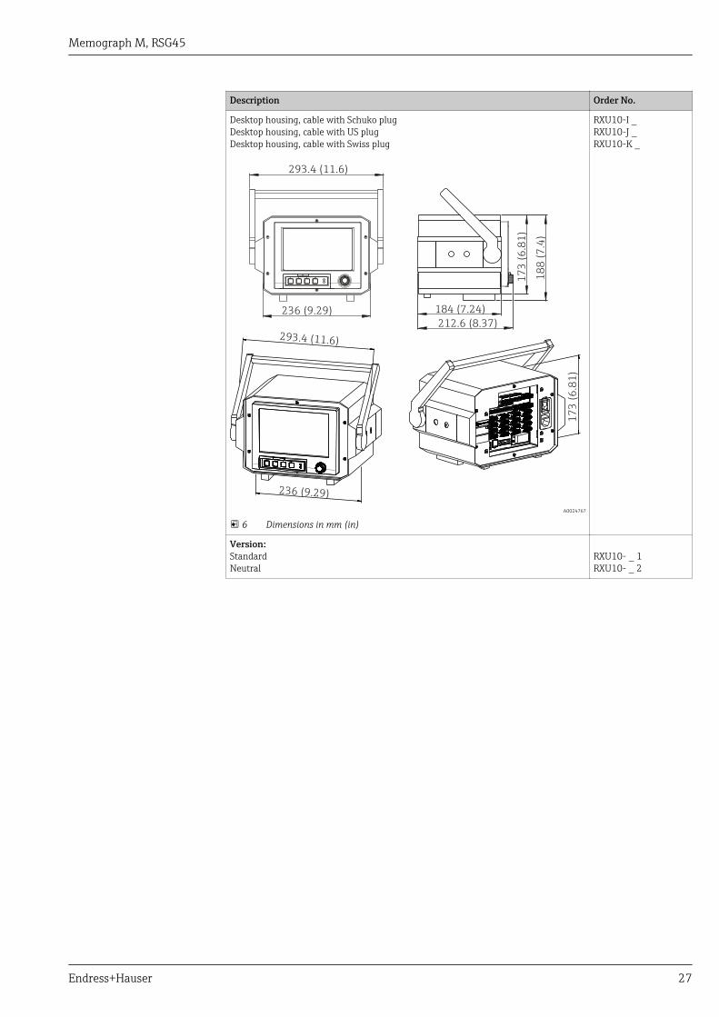
Description Order No.
Desktop housing, cable with Schuko plugDesktop housing, cable with US plugDesktop housing, cable with Swiss plug
293.4 (11.6)
236 (9.29)
17
3 (
6.8
1)
18
8 (
7.4
)
17
3 (
6.8
1)
212.6 (8.37)
184 (7.24)
293.4 (11.6)
236 (9.29)
A0024767
6 Dimensions in mm (in)
RXU10-I _RXU10-J _RXU10-K _
Version:StandardNeutral
RXU10- _ 1RXU10- _ 2

www.addresses.endress.com