memory management - nob.cs.ucdavis.edunob.cs.ucdavis.edu/classes/ecs150-2008-02/notes/memory.pdf ·...
TRANSCRIPT
ECS 150 (Operating Systems) Memory Management
Spring Quarter 2008 1
M e m o ry M a na gem e n tM e m o ry M a na gem e n t Goal
CPU gains related to scheduling require that many processes be in memory; so, memory must be shared. We shall discuss memory management schemes; the selection of which one to use depends especially on the hardware available.

ECS 150 (Operating Systems) Memory Management
Spring Quarter 2008 2
How Programs Interact With Memory
When a program is written and then run, the following steps take place:
compile, assemble to object module linker to load module loader to in-core image execute
Addresses in each of these are: SOURCE symbolic compile bind to relocatable address, i.e.,
bigmod + 4 loader (usually) bind relocatable to
closest address A program executes using absolute (also called physical) addresses; here's what the instruction execution cycle looks like: fetch instruction at address A decode it (poss) fetch operands at addresses B1, ..., Bn execute instructions (poss) store results at addresses D1, ..., Dn So the memory unit sees just a stream of addresses, and is never told how this stream is generated. We are just interested in this sequence.
ECS 150 (Operating Systems) Memory Management
Spring Quarter 2008 3
Memory Management and Hardware Bare Machine
This type has no memory management and no operating system software. simple: no special hardware no services problems: operating system has no control over interrupts no monitor to process system calls or errors no job sequencing This type of machine is used in dedicated systems when simplicity and flexibility are required and users are willing to program support routines.
Resident Monitor
In this type of system, there are 2 sections of memory: one for the monitor, the other for the user. The monitor is usually put wherever more convenient; as the interrupt vectors are usually in low memory, so is the monitor.
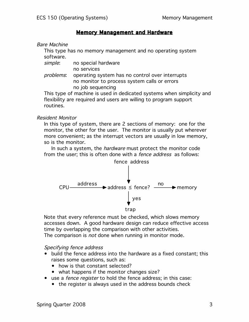
In such a system, the hardware must protect the monitor code from the user; this is often done with a fence address as follows:
CPUaddress
address ! fence?
fence address
yes
trap
nomemory
Note that every reference must be checked, which slows memory accesses down. A good hardware design can reduce effective access time by overlapping the comparison with other activities. The comparison is not done when running in monitor mode. Specifying fence address • build the fence address into the hardware as a fixed constant; this
raises some questions, such as: • how is that constant selected? • what happens if the monitor changes size?
• use a fence register to hold the fence address; in this case: • the register is always used in the address bounds check
ECS 150 (Operating Systems) Memory Management
Spring Quarter 2008 4
• the fence register may be loaded in monitor mode only, using a special, privileged instruction
ECS 150 (Operating Systems) Memory Management
Spring Quarter 2008 5
Relocation Typically, the address space of a computer starts at 0, but as the monitor is in low memory, the address space of a user process starts at the first address after the fence address. So when are program addresses bound to absolute addresses? • at compile time? if the fence address is known, this is possible. problem: if the fence address changes, the code must be recompiled. • at load time? In this case, the compiler generates relocatable code. problem: if the fence address changes, the code must be reloaded Further, both of these assume the fence address is static during execution; if it changes, then the program could produce invalid addresses midway through execution. This means that under these schemes the fence address can be changed only when no user processes are running. This becomes a big problem when the monitor uses transient monitor code. This involves little-used routines within the monitor. To keep the monitor small, the transient monitor routines are not loaded until needed; when they are needed, the monitor size increases, so the fence address changes; when the routine is no longer needed, it is deleted and the fence address changes again. Hence allowing the monitor to change size dynamically is good, and neither of those alternatives allow it.
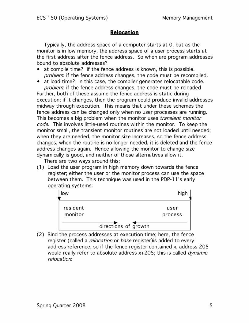
There are two ways around this: (1) Load the user program in high memory down towards the fence
register; either the user or the monitor process can use the space between them. This technique was used in the PDP-11's early operating systems:
low high
resident
monitor
user
process
directions of growth (2) Bind the process addresses at execution time; here, the fence
register (called a relocation or base register)is added to every address reference, so if the fence register contained x, address 205 would really refer to absolute address x+205; this is called dynamic relocation:

ECS 150 (Operating Systems) Memory Management
Spring Quarter 2008 6
CPUlogical
address
base
register
memoryabsolute
address
The CDC 6600s use this scheme. Advantages:
• The user process never sees the absolute (physical) addresses. • If the base register is changed, the user memory need only be
moved to the correct locations relative to the new fence address. With this scheme, the user process sees the logical addresses as 0, ..., max , but the physical addresses are really b, …, b+max, where b is the fnece address (contents of base register). Note that all information passed to the operating system for use as memory addresses (such as buffers for I/O) must be relocated.] This concept of the logical address space being mapped to a separate physical address space is central to proper memory management!
(3) Swapping This uses the idea of a (single-user) resident monitor, but for many
processes by keeping only one process resident and putting all others on backing store (called the swap device). The first idea is to use this when the system does not have enough memory for more than one user process at a time. • done in CTSS and the SDC Q-32 resident monitors, which make
the rest of memory available to current users; it is still used when there is not enough memory for all jobs
This was later generalized to many resident processes. • Called swapping; processes resident in memory are swapped. • The system needs a backing store which is big enough to hold
copies of all memory images for all users and provides direct access to them.
Executing a process now looks like this: • CPU calls dispatcher • dispatcher looks; if process in memory, runs it • if not, swap out resident process • swap in desired process • load registers as normal • run!
Swap Time
ECS 150 (Operating Systems) Memory Management
Spring Quarter 2008 7
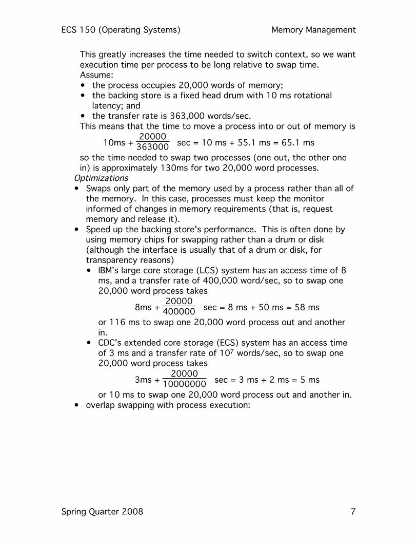
This greatly increases the time needed to switch context, so we want execution time per process to be long relative to swap time. Assume: • the process occupies 20,000 words of memory; • the backing store is a fixed head drum with 10 ms rotational
latency; and • the transfer rate is 363,000 words/sec.
This means that the time to move a process into or out of memory is
10ms + 20000363000 sec = 10 ms + 55.1 ms = 65.1 ms
so the time needed to swap two processes (one out, the other one in) is approximately 130ms for two 20,000 word processes.
Optimizations • Swaps only part of the memory used by a process rather than all of
the memory. In this case, processes must keep the monitor informed of changes in memory requirements (that is, request memory and release it).
• Speed up the backing store's performance. This is often done by using memory chips for swapping rather than a drum or disk (although the interface is usually that of a drum or disk, for transparency reasons) • IBM's large core storage (LCS) system has an access time of 8
ms, and a transfer rate of 400,000 word/sec, so to swap one 20,000 word process takes
8ms + 20000400000 sec = 8 ms + 50 ms = 58 ms
or 116 ms to swap one 20,000 word process out and another in.
• CDC's extended core storage (ECS) system has an access time of 3 ms and a transfer rate of 107 words/sec, so to swap one 20,000 word process takes
3ms + 2000010000000 sec = 3 ms + 2 ms = 5 ms
or 10 ms to swap one 20,000 word process out and another in. • overlap swapping with process execution:
ECS 150 (Operating Systems) Memory Management
Spring Quarter 2008 8
fence
address
monitor
swap-out
buffer
swap-in
buffer
user
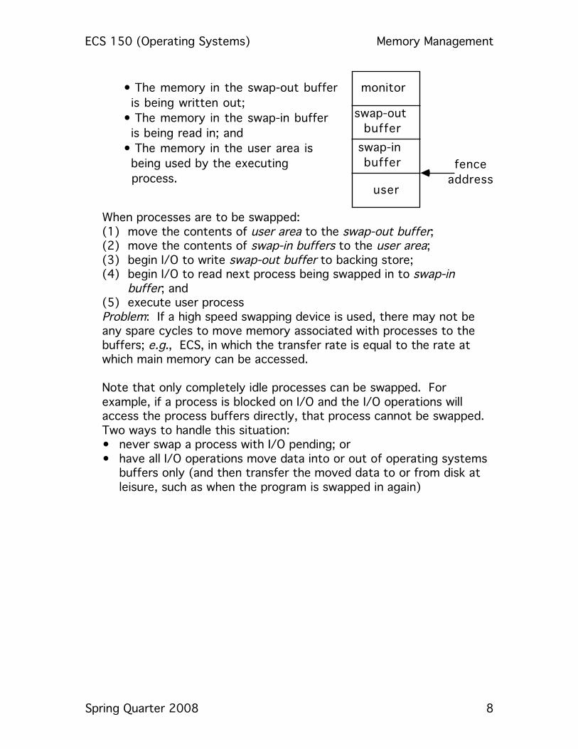
•!The memory in the swap-out buffer
!!is being written out;
•!The memory in the swap-in buffer
!!is being read in; and
•!The memory in the user area is
!!being used by the executing
!!process.
When processes are to be swapped: (1) move the contents of user area to the swap-out buffer; (2) move the contents of swap-in buffers to the user area; (3) begin I/O to write swap-out buffer to backing store; (4) begin I/O to read next process being swapped in to swap-in
buffer; and (5) execute user process Problem: If a high speed swapping device is used, there may not be any spare cycles to move memory associated with processes to the buffers; e.g., ECS, in which the transfer rate is equal to the rate at which main memory can be accessed. Note that only completely idle processes can be swapped. For example, if a process is blocked on I/O and the I/O operations will access the process buffers directly, that process cannot be swapped. Two ways to handle this situation: • never swap a process with I/O pending; or • have all I/O operations move data into or out of operating systems
buffers only (and then transfer the moved data to or from disk at leisure, such as when the program is swapped in again)
ECS 150 (Operating Systems) Memory Management
Spring Quarter 2008 9
Simple Memory Management Schemes As swapping is so expensive, we'd like to avoid it. This leads to the
idea of multiple partitions of memory, where multiple processes are stored in memory simultaneously, each in a different location. The question is how memory is allocated so processes need not be swapped out.
In general, memory is divided into partitions or regions, each with one program. • the degree of multiprogramming is bounded by the number of
partitions • when a partition is free, put a job on the ready queue into the partition Note the memory associated with each job is contiguous. Two schemes which do this are: • multiple contiguous fixed partition allocation (MFT) • multiple contiguous variable partition allocation (MVT) These require hardware to prevent access outside assigned memory regions. One of two mechanisms is typically used: • bounds registers keep track of the uppermost and lowermost physical
addresses • base and limit registers keep track of the uppermost logical address
and the smallest physical address (used in the CDC 6600 and its descendants)
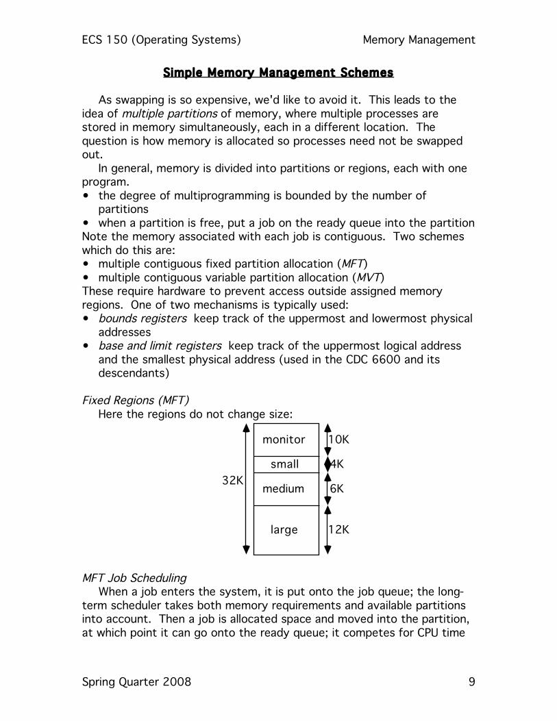
Fixed Regions (MFT)
Here the regions do not change size:
monitor
small
medium
large
10K
4K
6K
12K
32K
MFT Job Scheduling
When a job enters the system, it is put onto the job queue; the long-term scheduler takes both memory requirements and available partitions into account. Then a job is allocated space and moved into the partition, at which point it can go onto the ready queue; it competes for CPU time
ECS 150 (Operating Systems) Memory Management
Spring Quarter 2008 10
until it ends, at which point the memory partition is freed and a new job is brought in.
Allocation of Memory
All these require some classification of jobs based on memory needs as they enter the system. Either the user must specify a maximum amount of memory or the system can try to determine it automatically. (1) each memory partition has its own queue, and the job goes into the
smallest region that will hold it. Example: 3K job and 5K job go into the queues associated with the
small and medium partitions, respectively. (2) all jobs go into 1 queue, and when the scheduler selects the next job
to run, it waits for the partition to become available. Example: if a 3K job came first in the queue followed by a 5K job, and
the 6K partition became available, no job would be placed into it, because the next job in the queue is to go in the small partition.
(3) all jobs go into 1 queue, but when the scheduler is to bring in a job, it runs down the queue and picks the next job that would fit into an appropriate free partition
Example: if a 3K job came first in the queue followed by a 5K job, and the 6K partition became available, the 5K job would be put into the 6K partition even though the 3K job precedes it in the queue. (Note: if the 12K partition became free instead of the 6K partition, the 5K job sits in the queue as its associated partition is still occupied.) • the scheduler selects the next job that fits into its free partition
even if higher priority jobs are waiting ahead of it but are too large to run.
(4) all jobs go into 1 queue, but when the scheduler is to bring in a job, it runs down the queue and picks the next job that would fit into any free partition
Example: if a 5K job were in the queue, the small and medium partitions were occupied, and the large partition became available, the 5K job would be put into the 12K partition.
(5) Now add swapping and give each of several jobs fitting into one partition some time.
Example: We have 3 partitions; schedule all jobs associated with one partition using round robin. It works like this: • round robin quantum expires; • memory manager starts swapping out the job currently in the
partition and swapping in another job associated with that partition;
• the CPU scheduler gives a time slice to a job in another partition …

ECS 150 (Operating Systems) Memory Management
Spring Quarter 2008 11
For this to work the memory manager must be able to swap jobs fast enough so there are always jobs in memory, ready to execute, when the CPU is rescheduled.
(6) When a high priority job comes in and a lower priority one is using the appropriate partition (or lower priority jobs are using all available partitions), swap out a lower priority job for the higher priority one demanding service. • when the higher priority job is done, swap the lower priority job
back in and continue • this technique is called roll-out/roll-in Normally, swapped jobs return to same partition, but whether this must be done is dictated by the partition allocation policy and the relocation method: • with static relocation, the job must return to its original partition. • with dynamic relocation, the job need not return to its original
partition.
Problems: suppose a job needs more memory, or tries to allocate more memory, than the partition has. MFT gives the job a fixed amount of memory; the job may use less, but not more. So what can happen if it requests more? (1) terminate the job (2) return control to the job with an error indication that the request
cannot be satisfied (3) swap out the job and wait for a large enough partition to become
available; this is viable only if relocation is dynamic. Another problem: suppose your system has 120K of memory available,
and you run 20K jobs all day, except for one 80K job which runs once a day. You'll need an 80K partition to run that job, which means during most of the day you'll be wasting 60K (except when the 80K job is running).
Variable Regions (MVT)
This scheme allows partition size to vary dynamically to solve the second problem above. The operating system keeps track of what parts of memory are allocated and what parts are free (the holes) using bit maps or linked lists (or some other appropriate structure).
ECS 150 (Operating Systems) Memory Management
Spring Quarter 2008 12
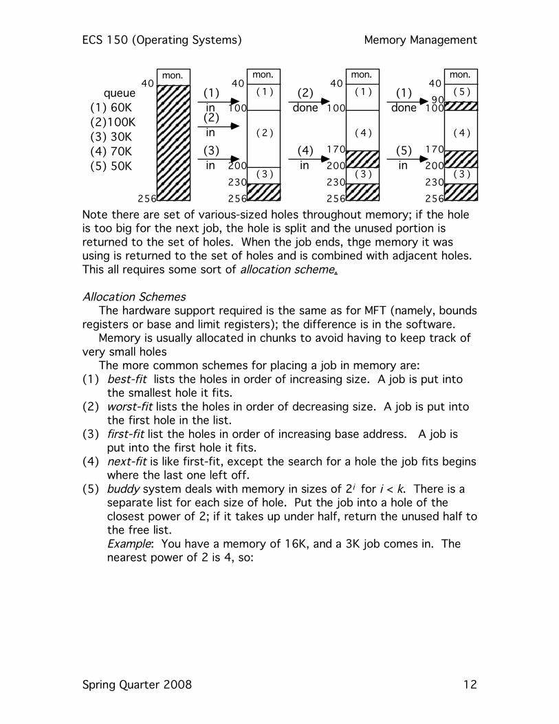
queue
(1)!60K
(2)100K
(3)!30K
(4)!70K
(5)!50K
mon.40
(1 )
(2 )
(3 )
100
200
230
256
mon.40
256
(1)
in(2)
in
(3)
in
mon.40
(1 )
(4 )
(3 )
100
200
230
256
170
(2)
done
(4)
in
mon.40
(5 )
(4 )
(3 )
100
200
230
256
170
(1)
done
(5)
in
90
Note there are set of various-sized holes throughout memory; if the hole is too big for the next job, the hole is split and the unused portion is returned to the set of holes. When the job ends, thge memory it was using is returned to the set of holes and is combined with adjacent holes. This all requires some sort of allocation scheme. Allocation Schemes
The hardware support required is the same as for MFT (namely, bounds registers or base and limit registers); the difference is in the software.
Memory is usually allocated in chunks to avoid having to keep track of very small holes
The more common schemes for placing a job in memory are: (1) best-fit lists the holes in order of increasing size. A job is put into
the smallest hole it fits. (2) worst-fit lists the holes in order of decreasing size. A job is put into
the first hole in the list. (3) first-fit list the holes in order of increasing base address. A job is
put into the first hole it fits. (4) next-fit is like first-fit, except the search for a hole the job fits begins
where the last one left off. (5) buddy system deals with memory in sizes of 2i for i < k. There is a
separate list for each size of hole. Put the job into a hole of the closest power of 2; if it takes up under half, return the unused half to the free list.
Example: You have a memory of 16K, and a 3K job comes in. The nearest power of 2 is 4, so:

ECS 150 (Operating Systems) Memory Management
Spring Quarter 2008 13
16K
8K
8K
8K
4K
4K3K goes
here
When done, the process reverses and blocks coalesce. Which works best? The buddy system. Job Scheduling
The scheduler has a list of available block sizes and a queue of jobs wanting memory. The job scheduler orders jobs according to its scheduling algorithm, and then memory is allocated until there is not enough to allocate to the next job. At that point, two things can be done: (1) skip to the next job in queue which can fit into the available memory
hole; or (2) wait until enough memory becomes available for the next job to be
run. Within a partition, MVT wastes little or no space (the wasting of space within a partition is called internal fragmentation), but between partitions it may waste lots of space (the wasting of space between partitions is called external fragmentation), no internal fragmentation; for example, in the earlier picture, job (5) could have been run simultaneously with (1), (3), and (4) were the two holes combined. But they weren't, so we has 56K of external fragmentation. The placement algorithm chosen can have a serious impact on the amount of external fragmentation. Compaction
This refers to moving the contents of memory about in order to combine holes. For example, in the above, move job 3's memory to 170K would combine the holes at 170K-200K and 230K-256K into one hole at 200K-256K. This is not always possible, and dynamic relocation is a necessity; you just copy the contents of the memory being used by the process, and change the base register appropriately.
Various schemes: (a) move all jobs to one end of memory; this can get expensive.

ECS 150 (Operating Systems) Memory Management
Spring Quarter 2008 14
(b) move enough jobs to get the memory you need. Example: the CDC 6600 Scope Operating System kept 8 jobs in main memory at once, and used compaction on job termination to keep one hole at the bottom of main memory Swapping
This can be useful too. Rolling out a job releases memory; rolling in can cause problems if static relocation is used (as it must have the same partition as when rolled out). Using dynamic relocation, though, you can swap the job out and then swap it in at its new location. Reducing external fragmentation:
This can be done in a number of ways: • reduce the average job size • break memory into two parts, one for instructions and one for data. example: PDP-10 had 2 base/limit register pairs, the high order bit of
each indicating which half of memory (high or low) the pair refers to. Instructions and read-only data go into high memory and variables go into low memory (by convention).
example: UNIVAC 1108 also had 2 base/limit register pairs, one for instructions and one for data. The instruction pair is read-only, so users can share programs.

ECS 150 (Operating Systems) Memory Management
Spring Quarter 2008 15
Memory Fragmentation Say a job needs w words of memory, and a partition has p words.
Then: internal fragmentation exists when w - p > 0 (ie, memory internal to a
partition is not being used) external fragmentation exists when w – p < 0 (ie, a partition is unused
and available but is too small for any waiting job) example: A system has 22K memory available; it is divided into 4 partitions of sizes 4K, 4K, 4K, and 10K. The queue has:
7K job ←10K partition, leaving 3K of internal fragmentation 3K job ← 4K partition, leaving 1K of internal fragmentation 6K job waits two 4K partitions unused, leaving 8k of external fragmentation
Total fragmentation: 8K+3K+1K=12K, which is over 50% of available memory! example: A system has 22K memory available; it is divided into 3 partitions of sizes 4K, 8K, and 10K. The queue has:
7K job ← 8K partition, leaving1K of internal fragmentation 3K job ← 4K partition, leaving1K of internal fragmentation 6K job ← 10K partition, leaving4K of internal fragmentation all partitions used, leaving 0K of external fragmentation
Total fragmentation: 0K + 4K + 1K + 1K = 5K, which is 23% of available memory; much better. example: partitions exactly match job sizes (in the above, the 22K memory is divided into partitions of 3K, 6K, 6K, and 7K). Total fragmentation: 0K (ie, none)!

ECS 150 (Operating Systems) Memory Management
Spring Quarter 2008 16
Paging This solves the compaction problem of MVT by no longer requiring program memory to be contiguous. The hardware splits each logical address into two parts; the high bits represent the page number and the low bits the page offset. A page table has the base address (frame number) of each page in physical memory; this base added to the offset to get the associated physical address:
page 0
page 1
page 2
page 3
logical
memory
4
2
0
5
page
table
page 2
page 1
page 0
page 3
physical
memory
A frame is the physical memory into which a page is put; a page is the unit of logical memory put into physical memory. Both are of the same fixes size, which is defined by hardware, and is usually a power of 2; some examples:
IBM 370 2048 or 4096 bytes/page XDS-940 2048 words/page NOVA 3/D 1024 words/page DEC-10 512 words/page
If the page contains p words, the logical address l gives: page number = l div p page offset = l mod p
If p is a power of 2, this can be done by examining the bit representation of l directly:
page number = high order bits of p page offset = low order bits of p
example: for a 16 word memory, and a page size of 2 words:

ECS 150 (Operating Systems) Memory Management
Spring Quarter 2008 17
a b c d e f g h
0 2 4 6
logical
memory2 6 4 5
page
table
0 1 2 3
a b
0 2 4 6 8 10 12 14
c de f g hphysical
memory
To obtain the physical address of word h (word number 7):
page number = 7 div 2 = 3 page offset = 7 mod 2 = 1
The page table says page number 3 is mapped into frame number 5, so the base of the frame is 5 x page size = 10, and hence the physical address corresponding to logical word 7 is 10 + 1 or 11.
This transformation is done for every logical address, so it is dynamic relocation.
Job Scheduling
Job size is given in pages; if a job has n pages, it needs n free frames. Note there is no external fragmentation! But there will be internal fragmentation if the last page of the job uses less than 1 full page. If the job size and page sizes are independent, the expected internal fragmentation is half a page per job; so to minimize internal fragmentation, use small page sizes
Page table information is stored in the process' PCB; if the process is swapped back in, those values may have to be updated to reflect the new placement. Page table implementation
If there is a small number of pages, use registers for the page table. Loading and modifying their contents requires privileged instructions. examples: XDS-940 8 pages 2048 wds/page 8 registers NOVA 3/D 32 pages 1024 wds/page 32 registers SIGMA 7 256 pages 1024 wds/page 256 registers These can be built from very high speed logic, so paging address translation is efficient. If there is a large number of pages, then store the page table in memory, and use a Page Table Base Register (PTBR) to point to it.
ECS 150 (Operating Systems) Memory Management
Spring Quarter 2008 18
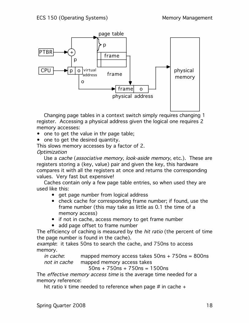
CPU
p
o
p
physical
memory
page table
frame
+PTBRframe
frame o
physical address
p o virtual
address
Changing page tables in a context switch simply requires changing 1
register. Accessing a physical address given the logical one requires 2 memory accesses: • one to get the value in thr page table; • one to get the desired quantity. This slows memory accesses by a factor of 2. Optimization
Use a cache (associative memory, look-aside memory, etc.). These are registers storing a (key, value) pair and given the key, this hardware compares it with all the registers at once and returns the corresponding values. Very fast but expensive!
Caches contain only a few page table entries, so when used they are used like this:
• get page number from logical address • check cache for corresponding frame number; if found, use the
frame number (this may take as little as 0.1 the time of a memory access)
• if not in cache, access memory to get frame number • add page offset to frame number
The efficiency of caching is measured by the hit ratio (the percent of time the page number is found in the cache). example: it takes 50ns to search the cache, and 750ns to access memory.
in cache: mapped memory access takes 50ns + 750ns = 800ns not in cache mapped memory access takes
50ns + 750ns + 750ns = 1500ns The effective memory access time is the average time needed for a memory reference: hit ratio ¥ time needed to reference when page # in cache +

ECS 150 (Operating Systems) Memory Management
Spring Quarter 2008 19
(1 - hit ratio) × time needed to reference when not in cache example: in the above, an 80% hit ratio gives an effective memory access time of:
0.8 ¥ 800ns + (1 - 0.8) × 1550ns = 956ns
for a slowdown of 956-750750 = 27.4%, and a hit ratio of 90% gives
0.90 × 800ns + (1 - 0.9) 1550ns = 875ns
for a slowdown of 875-750750 = 16.7%).
Sharing Pages Pages of re-entrant code (non-self modifying code, pure code) can be shared simply by putting appropriate entries in the page tables:
C2
data 1
C1
data 2
memory
C1
C2
data
job 1
4
2
0
page
table
C1
C2
data
job 1
4
2
3
page
table
0
1
2
3
4
5
Here the total space used with sharing is 2 pages for C, 3 data pages The total space used without sharing is 2 pages for C, 3 data pages It is critical that shared code not be changed; so this must be enforced by the operating system, and not by the code itself. Protection Associate protection bits with each page. These bits are kept in the page table:
• 1 bit for read/write or read only • 1 bit for valid/invalid • additional bits for other forms of protection
With these the system can verify there is no writing to a read-only page while the physical address is being computed; if there is such writing, a trap to the operating system occurs. How il legal addresses get trapped The operating system sets a bit for each page to allow/disallow access. example: 14-bit address space (0 … 16383), and the program uses addresses 0 … 10468. The page size is 2048 words/page. Hence

ECS 150 (Operating Systems) Memory Management
Spring Quarter 2008 20
ppages 6 and 7 cannot be accessed. As an example of internal fragmentation, note that words up to 12287 can be accessed because page 5 contains some part of the program, and you can't deny access to part of a page (it's all or nothing). A quick review of what we've done so far, but from another direction:

ECS 150 (Operating Systems) Memory Management
Spring Quarter 2008 21
Views of Memory The user's program sees one contiguous memory space. The operating system sees the user's program scattered throughout
physical memory . How can these be reconciled? Because the address translation
mechanism maps logical memory locations to physical locations, under the control of the operating system.
This means: • the logical and physical addresses may be different example: the XNS-940 has a logical address of 14 bits but a physical
address of 16 bits; the page number (3 bits) goes into the Page Table to select a 5 bit frame number. Hence there is up to 4 times as much physical memory as one user can address
This technique was used when 15/16 bit address spaces grew to 17/18 bits as memory prices dropped: • the logical addresses were still 15/16/ bits; • the physical addresses became 17/18 bits. Users could not use more memory than before, however.
The operating system is aware of what frames are allocated, what frames are available, the total number of frames, etc.; all this is stored in a global frame table , which is like a page table but has one entry per frame. The entry indicates if the frame is allocated and if so, to which process.
ECS 150 (Operating Systems) Memory Management
Spring Quarter 2008 22
Segmentation Now alter the user's view of memory slightly; instead of sets of equally-sized blocks of instructions or data, think of a program as a collection of variable-sized segments:
• 1 segment per subroutine or data structure • segments are of variable length • words (elements) identified by offsets into segment
This form of memory management is called segmentation: • the logical address space is a collection of segments, • segments have a name and a length • addresses specify the name of the segment and the offset
into that segment In paging, the hardware divides the logical address into a page number and offset; but for a segmented system, the operating system is given the segment number and the offset. (It is often generated by the compiler, although the user may do it directly — the “.text n” construct in many assemblers says to put the following instructions into text segment n.)
Segments are "named" by numbers because it's the easiest thing to do. When a program is assembled, the assembler (or compiler) constructs segments appropriate for the program. example: In a C program, there might be:
• a segment for global variables • a segment for the process call stack (in which arguments are
stored, values returned, etc.) • segments for the code for each function • segments for local variables for each function
The loader assigns segments numbers. Users refer to objects by a pair (segment name, offset) that must be
mapped to a physical address. A Segment Table is used for this:
ECS 150 (Operating Systems) Memory Management
Spring Quarter 2008 23
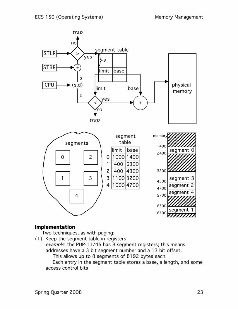
CPU (s,d)
s
baselimit
<
trap
d
s
no
yes+
physical
memory
segment table
limit base
+STBR
>yes
no
trap
STLR
limit base
1000
400
400
1100
1000
1400
6300
4300
3200
4700
segment
table
4
3
2
1
00
1
2
3
4
segments1400
2400
3200
4300
4700
5700
6300
6700
segment 0
segment 3
segment 2
segment 4
segment 1
memory
Implementation Two techniques, as with paging: (1) Keep the segment table in registers example: the PDP-11/45 has 8 segment registers; this means
addresses have a 3 bit segment number and a 13 bit offset. This allows up to 8 segments of 8192 bytes each. Each entry in the segment table stores a base, a length, and some
access control bits

ECS 150 (Operating Systems) Memory Management
Spring Quarter 2008 24
example: the B5500 has 32 segments of1024 words, so segment numbers are 5 bits long and offsets are 10 bits. Problems: too few segments, too little memory per segment
(2) Keep the segment table in memory In this case, the Segment Table Base Register points to the base of
the segment table, and the Segment Table Length Register contains the number of segments for the program. Hence two steps to getting the physical address, given a logical address (s,d):
(1) Check that s < contents of STLR; if not, bad address (2) The location of the entry for the segment is STBR[s]
Now proceed as above. As with paging, there will be 2 memory references per logical address; using a cache to hold the most recently used segment table entries reduces the effective memory access time. Using 8-16 such registers reduces the delay to 1.1 or 1.15 times that of unmapped memory access Protection
Segments represent semantically defined portions of programs, so all entries in a segment are protected in the same way. For example, instruction segments are usually read-only, execute-only. Typically associate protection bits with each segment table. Each array can be put in its own segment, which allows automatic bounds checking! Sharing
Segments can be shared:
ed
data
ed
data
process 1 process 2
2528
8550
4306
9000
limit base
0
1
0
1
0
1
seg table
2528
1223
4306
6834
limit base
0
1
seg table
4306
6834
7957
9000
17550
ed
data 2
data 1
memory
This means you need keep just one copy of non-writeable segments in memory! Also, you can share parts of program; for example, if 2 FORTRAN programs call sqrt(x), stick sqrt(x) into its own segment and keep just one physical copy of it in memory. Some subtleties:

ECS 150 (Operating Systems) Memory Management
Spring Quarter 2008 25
• a conditional jump in a shared segment uses an address to transfer to; that address is a (segment number, offset) pair. The segment number is that of the code segment. So if it is shared, the shared code segment must have the same number in all sharing processes.
example: Sqrt shared; in one process it's segment number 4, and in another, it's segment 17. How can sqrt refer to itself? It can't; so it must have a number common to all processes sharing it.
solutions: • only share read-only data segments without any pointers (which
contain addresses) • share code segments which refer to themselves indirectly example: addresses specified as offsets from current PC example: GE 645: addresses specified relative to a register containing
the current segment number. Fragmentation
Note that paging has a fixed size page length, but segmentation uses variable length blocks. So finding room for the segments is the dynamic storage allocation problem; use the first-fit, best-fit, ... algorithms.
The amount of external fragmentation depends on job scheduling and segment size; if there's no room, the system can:
• wait until there is room; • skip this job and put in the next one that fits; • compact memory

ECS 150 (Operating Systems) Memory Management
Spring Quarter 2008 26
Segmentation and Paging These can be combined in two ways: • Segmented paging Segment the page table; that is, each entry in the segment table
contains the base and length of (part of) the page table. • logical address is (page number, page offset), but the page number
itself is (segment number, segment offset) So:
1. get segment number, add STBR 2. get segment table entry 3. compare segment offset with page table length; if offset greater,
illegal reference 4. get page table base, add segment offset 5. get page table entry 6. use the frame number in it and the page offset to get physical
location This scheme is used when most of the page table is empty, which
happens when the address space is big and the programs use a fraction of the space of memory.
• Paged Segmentation Here, the segments are paged. The segment table contains the
segment lengths and the page table base logical address • logical address is (segment number, segment offset), but the
segment offset is really (page number, page offset), and entries in the segment table are (page table base, page table length)
So: 1. get segment number, compare to segment table length; if number
greater, illegal reference 2. add STBR to segment number 3. get segment table entry 4. add page number to page table base address 5. get page table entry 6. use the frame number in it and the page offset to get physical
location

ECS 150 (Operating Systems) Memory Management
Spring Quarter 2008 27
(s,d)
s
s
physical
memory
segment table
+STBR
>yes
no
trap
STLR
PTBR
p
(p,o) +p
page table
f (f,o)
d
CPU
This is used when segment sizes are large and external fragmentation
is a problem, or finding free space takes a long time. As with paging, note the last page of each segment is generally not full; on the average, there is half a page of internal fragmentation per segment. But there is no external fragmentation!

ECS 150 (Operating Systems) Memory Management
Spring Quarter 2008 28
What Is Virtual Memory Virtual memory allows the execution of processes not completely in
memory. Why is this good? • programs often have code to handle unusual error conditions; in many
cases, this code may almost never be used; • arrays and tables are often allocated more memory than needed; • some options and features are seldom used and even if all are used,
they are seldom used all at once. Some added benefits of not requiring the whole program to be in memory are: • programs are not constrained by the amount of available physical
memory; • more users can run at the same time, increasing CPU utilization and
throughput, without increasing response or turnaround times; • it takes less I/O to load or swap a process into memory, so each user
process seems to run faster How can this be done? In several ways:
ECS 150 (Operating Systems) Memory Management
Spring Quarter 2008 29
Overlays For this technique, keep only the instructions and data needed at a given time in memory; as they are needed, new instructions and data are loaded into space occupied by instructions and data no longer needed. Example: consider a two-pass assembler:
pass 1 8K pass 2 10K symbol table 14K common routines 5K total 37K
The system has 32K of memory available. So, define two overlays: 1. pass 1, symbol table, common routines; total, 27K 2. pass 2, symbol table, common routines; total, 29K
Add an overlay driver of 2K, and both overlays fit into memory completely. Thus, you load overlay 1 into memory, run, and when you finish jump to the overlay driver, which loads overlay 2 into memory and invokes it. This is an example of This is an example of dynamic loading, on which the routine is not loaded until it is needed. It requires that routines be kept on disk in a relocatable format. When the main program is loaded and executed, and it calls a routine, the system:
(1) checks to see if the called routine is in memory (2) if not, that routine is loaded and the relevant tables are
updated (3) the called routine is executed.
Advantage: only routines that are used get loaded. Note that the operating system need provide no special support; however, this means: Problem: the user must design and program an overlay structure or loading; since the program is large, this may get confusing. It would be far preferable to have automatic mechanisms to do this. This mechanism is called …

ECS 150 (Operating Systems) Memory Management
Spring Quarter 2008 30
Implementations of Virtual Memory It describes a set of techniques for allowing execution of a program
not in memory. One such technique is: Demand Paging
Programs reside on a backing store (swapping device). Only those pages being used are brought in; a page is never brought in unless it is referenced. • this decreases swap time and the amount of physical memory needed; • it also increases the degree of multiprogramming.
To indicate a page is not resident (in memory), set the invalid bit for page table entries referring to pages not in memory. When the process references such a page, the process page faults.
Pure demand paging means the process starts executing with no pages in memory. The first action (getting the first instruction) causes a page fault; the appropriate page is loaded, etc. …. Hardware Support for demand paging. Needed are: • a page table which can have entries marked invalid via a valid/invalid
bit or some special value of protection bits; and • a backing store for pages not in memory. Performance Issues Let ma be the memory access time (typically, 500ns - 2µs), and p the probability of a page fault. Then the effective memory access time emat is:
ma(1–p) + p(page_fault_service_time ) What happens on a page fault?
1. There is a trap to the operating system. 2. User registers and program state are saved. 3. The operating system determines that the trap was a page
fault trap. 4. The operating system checks that the page reference was
legal, and if so determines the location of the page on the backing store.
These first 4 steps (servicing the page fault trap) take 100-1000µs. 5. The operating system initiates a read of the page from the
backing store to a free frame: a. the request waits in the appropriate queue for the device; b. it waits for the device seek and rotational latencies; c. the page transfer begins.
6. While waiting for the I/O to complete, the operating system reallocates the CPU to another process.
7. When the I/O completes, an interrupt occurs.

ECS 150 (Operating Systems) Memory Management
Spring Quarter 2008 31
8. Again, the system saves registers and program state of the currently running process.
9. The operating system determines the interrupt was from the backing store.
10. It updates the page table (and other tables) to show the page is now in memory.
These steps (swapping in the page) take approximately 9ms. 11. The operating system now reallocates the CPU. 12. The appropriate process is restarted. These first 4 steps (servicing the page fault trap) take 100-1000µs.
Given an average page fault service time of 10ms, and a memory access of 1µs, the effective memory access time is:
effective access time = (1 - p) 1µs + p10ms = (1 - p) + 10000 µs = (1 + 9999p) µs which means the effective access time is proportional to the page fault
probability. Hence, if p = 11000 , then
emat = (1 + 99991000 )µs = 10999
1000 µs ≈ 11µs that is, memory accesses are roughly 11 times slower due to demand paging. To get less than 10% degradation, we need: 1.1 ≥ 1 + 9999p Want less than 10% degradation? You need:
1110 > 1 + 9999p ⇒ p < 1
100000 or, in words, less than 1 memory access out of every 100,000 can page fault. Page Replacement Throughout, once a page has been loaded, it is kept in memory. But this may result in overallocating memory:
• When executing a program, a page fault occurs. • The hardware traps to the operating system, which sees it is page
fault. • The operating system determines where on backing store the
required page is. • But then the operating system cannot find a free frame!!!
It can do three things at this point: 1. Terminate the program problem: the whole idea behind demand paging is that it should be
hidden from the user.

ECS 150 (Operating Systems) Memory Management
Spring Quarter 2008 32
2. Swap out the process temporarily; more about this later. 3. Replace some pages in memory. If there are no free frames, find some
frame not in use and free it (by writing its contents to the backing store and changing all relevant tables).
So now the page fault service routine becomes: 1. Locate the desired page on the backing store. 2. Look for a free frame:
• if one is found, use it • if not, use a page replacement algorithm to select a victim
frame; write the page in this frame (called the victim page) to the backing store, and update the tables to show this
3. Read in the new page, and update the appropriate tables 4. Restart the user process
If there are no free frames, two page transfers (one out and one in) are required. To cut down on this overhead, associate with each page (frame) a dirty bit in the hardware; whenever any word or byte is written to the page, this dirty bit is set. When a page is chosen as a victim, if its dirty bit is set, write the page out; otherwise, don't bother. Stepping Back for a Moment
Now, virtual memory has become a separation of user logical memory from physical memory. The size of a virtual memory is no longer constrained by the size of the computer's physical memory; pages can be moved in and out as needed.
Of course, virtual memory can also be implemented using segments. Problems: The system needs both a page replacement algorithm and a frame allocation algorithm.

ECS 150 (Operating Systems) Memory Management
Spring Quarter 2008 33
Page Replacement Algorithms A reference string is this string of memory references.
example: consider the string of memory references on a system with 100-word pages:
100, 432, 101, 612, 102, 103, 104, 101, 611, 102, 103 This produces the reference string
1 4 1 6 1 6 1 Algorithms First In First Out (FIFO) This algorithm selects the oldest page for removal. Optimal (OPT, MIN) This algorithm selects the page that won't be used for the longest period of time. Least Recently Used (LRU) Associate with each page the time of last use; then this algorithm replaces the page not used for the longest period of time. Stack Algorithms These are a generalization of the LRU algorithm; a stack algorithm is one for which the set of pages in memory for n frames is a subset of set of pages which would be in memory for n + 1 frames. LRU is a stack algorithm, as is OPT.
LRU is too expensive to implement without hardware assistance - either using a stack or counters which are updated for every reference. Interrupts would have to occur at each reference, which would increase effective memory access time by a factor of 10 (at least). So … approximate it using other stack algorithms!
In all of these, whenever a page is referenced (read or write), the hardware sets a bit (called the used bit or reference bit) associated with each page. This is used to determine which pages have been used and which have not been used. example: Associate with each page a set of n bits (called an aging register). The high-order bit of this register is the use bit. At regular intervals, shift the register right one bit (losing the low-order bit). Hence each page has the last n use bits as a history. To replace the page referenced furthest in the past, replace the page with the lowest number in its associated aging register. Clock, Second Chance

ECS 150 (Operating Systems) Memory Management
Spring Quarter 2008 34
Whenever a page is referenced, the use bit is set. When a page must be replaced, the algorithm begins with the page frame pointed to. If the frame's use bit is set, it is cleared and the pointer advanced. If not, the page in that frame is replaced. (If the pages are kept on a circular list, it's “clock;” otherwise, it's “second chance.”) Least Frequently Used (LFU) A count of the number of references to a page is kept; the page with the smallest count is chosen to be the victim. Most Frequently Used (MFU) This is just like LFU, but selects as victim the page with the largest count, on the theory that the page with the smallest count has just been brought in and is waiting to be used. Not Used Recently (NUR, NRU) This essentially uses the second chance algorithm based on the use bits rather than the time the page is brought in. Consider the use bit and the dirty bit (which is set whenever the page is written to) as forming 4 classes (the first number is the use bit, the second the dirty bit). The classes are ordered as follows:
(0,0) → class 0; (0,1) → class 1; (1,0) → class 2; (1,1) → class 3 Pick a victim from the lowest numbered class. When a page is brought in, all use bits are cleared. example: see handout Second-Chance Cyclic This is like NUR but without the randomness. Use the same classes, but instead of selecting randomly, advance a pointer as in the clock algorithm. The class of the page the pointer is pointing to tells what to do:
class after (1,1) (0,1) (1,0) (0,0) (0,1) (0,0)* (0,0) select this page
example: see handout

ECS 150 (Operating Systems) Memory Management
Spring Quarter 2008 35
Ad Hoc Techniques for Improving Performance
The system can keep a pool of free frames. When a process needs a page, the page in read into a free frame in the pool before the victim is written out, and when the victim is written out its frame is added to the free frame pool. • The process need not wait for the victim to be written out; • The system can do I/O periodically rather than on each page
replacement (for example, when the number of free frames falls below some threshold); in this case, if a page is needed but has not yet been written out, its frame can just be removed from the free frame pool and reused (that is, no I/O needed). The VAX/VMS operating system uses this technique to improve FIFO by reducing I/O.
• If the paging device is idle, find pages with the dirty bit set, write them out, and then clear the dirty bit.
ECS 150 (Operating Systems) Memory Management
Spring Quarter 2008 36
Page Allocation Algorithms Several strategies are possible: • Use all frames before replacing pages; • Keep some free frames reserved so that when a page fault occurs, a
page can be brought in while the victim is being chosen. Problem with demand paging and multiprogramming: How does the system allocate frames to a process? • The most frames a process can get is all of them! • The least frames a process can get is defined by the architecture: As a page fault causes the current instruction to restart, this gives a
bound on the maximum number of pages a single instruction can reference
example: PDP-8: 1 memory address/instruction, so the minimum number of frames per process is: • 1 frame for the instruction • 1 frame for the address, which may be an indirect address
(pointer), so … • 1 frame for the value pointed to by an indirect address for at most 3 frames per instruction, and therefore at least 3 frames per process.
example: PDP-11: 2 memory addresses/instruction, as an instruction may be longer than 1 word; so the minimum number of frames per process is: • 2 frames for the instruction • 1 frame per address, which may be an indirect address (pointer), so
… • 1 frame for the value pointed to by an indirect address for at most 6 frames per instruction, and therefore at least 6 frames per process. example: Data General Nova 3: this allowed multiple levels of indirection. Each16 bit word has 15 bit addresses and 1 indirect bit, so the indirection could go on forever! The engineers modified the architecture to allow at most 16 levels of indirection, so each address requires at most 17 frames.
Global or Local Frame Allocation • Global allocation: frames for replacement pages are taken from the set
of all frames grab replacement from set of all frame Problems: (1) The program does not control its own paging behavior (2) The program may perform very differently due to external factors.

ECS 150 (Operating Systems) Memory Management
Spring Quarter 2008 37
• Local allocation: frames for replacement pages are taken from that process' set of frames ⇒ the number of frames allocated to a process does not change Equal Allocation: if there are m frames and n processes, each process
gets mn frames Proportional Allocation: Suppose the size of a process' virtual memory
is si, and let S be the sum of all si. Then process pi gets simS frames.
example: The system has 2 processes, one with a virtual memory of 10K and the other with 127K, and there are 62 free frames. • Under equal allocation, each process gets 31 frames • Under proportional allocation, the first gets
!
10 " 62
137= 5, and the
second
!
127 " 62
137= 57 frames.
Note that if the degree of multiprogramming goes up, each process losses frames, but if it drops, each process gets more frames Problem: all processes aretreated equal regardless of priority Solutions: (1) use a proportional allocation scheme based on priorities or a
combination of sizes and priorities (2) allow a high priority process to take frames from a low priority
process and use them for replacement.

ECS 150 (Operating Systems) Memory Management
Spring Quarter 2008 38
Thrashing Thrashing occurs when a process spends more time paging than
executing. A prime cause is that the set of pages needed to avoid faulting for every page will not fit into the process' set of page frames.
Suppose the operating system monitors CPU utilization and brings in a process if the degree of multiprogramming is too low. One scenario, on a system using a global page replacement algorithm, is: (1) a process needs more frames, and gets them from other processes; (2) those other processes begin page faulting, and queueing for the
paging device; (3) the ready queue empties; (4) CPU utilization drops; (5) more processes are brought in, and they grab pages from executing
processes; (6) more processes queue up for the paging device; … The throughout plunges. Processes pages, but do no work, and the effective memory access time increases.
degree of multiprogramming
CPU
uti
lizati
on
thrashing
A local replacement algorithm will limit the effect of page faulting to
one process, but increased contention for the paging device increases effective memory access time for all processes.

ECS 150 (Operating Systems) Memory Management
Spring Quarter 2008 39
Principle of locality
As a program runs, it moves from locality to locality That is, references tend to be grouped.
ECS 150 (Operating Systems) Memory Management
Spring Quarter 2008 40
Working Set Model Let the current time be t. Then
W(t, τ) = { pages referenced in last τ time units } where τ is the window size, or the size of the working set (a tuneable parameter). example: see handout.
This ties process management to memory management via the Working Set Principle:
A process may execute only if its working set is resident in main memory. A page may not be removed from main memory if it is in the working set of an executing process.
Properties: (1) the size of a working set can vary:
1 < |W(t, τ)| < min(τ, number of pages in process) (2) W(t, τ) ⊆ W(t, τ+1), so working set is a stack algorithm.
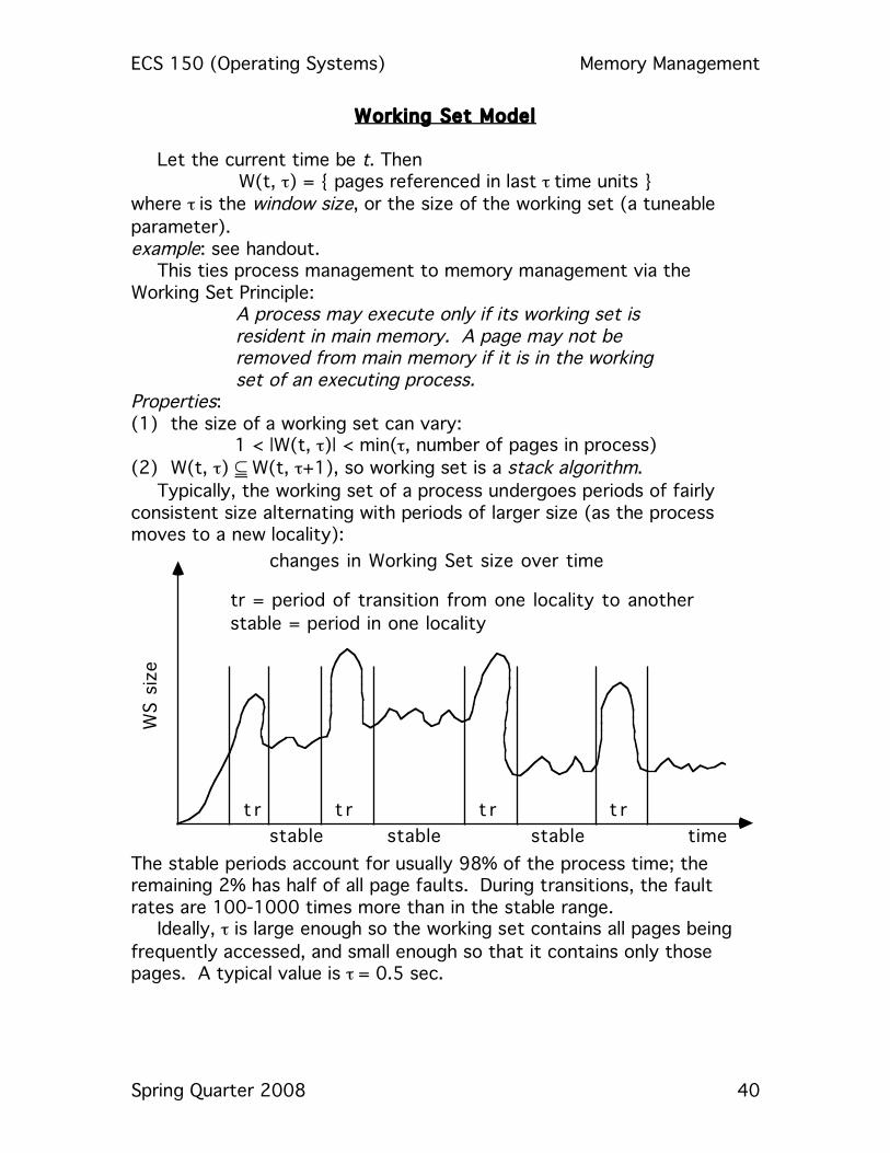
Typically, the working set of a process undergoes periods of fairly consistent size alternating with periods of larger size (as the process moves to a new locality):
WS s
ize
timestable stablestable
t r t r t r t r
changes in Working Set size over time
tr = period of transition from one locality to another
stable = period in one locality
The stable periods account for usually 98% of the process time; the remaining 2% has half of all page faults. During transitions, the fault rates are 100-1000 times more than in the stable range.
Ideally, τ is large enough so the working set contains all pages being frequently accessed, and small enough so that it contains only those pages. A typical value is τ = 0.5 sec.
ECS 150 (Operating Systems) Memory Management
Spring Quarter 2008 41
Implementation: It requires an accurate virtual clock. Whenever a page is accessed, the current time according to that clock is recorded in the page table. The working set contains all pages whose access time is within t of the present time. Problem: Too expensive.

ECS 150 (Operating Systems) Memory Management
Spring Quarter 2008 42
Working Set Approximations All try to approximate membership in the working set by examining
what pages have been referenced since the last page fault or last few faults. The algorithms differ in the way they examine the pages in the system to decide how to do this approximation.
WSCLOCK
With this algorithm, use a clock type scan through the frame table. A page fault in any process starts the scan. • use bit set: Clear it and store the virtual time of the process owning the page in
that frame in a referenced time field; this is an approximation of when the page was last referenced.
• use bit clear: Compare current virtual time of the process owning the page in that frame in a referenced time field; if the difference is more than t, the page is not in the process' current working set and can be removed.
If no page can be removed, swap out a process Working Set Size (WSS)
The memory manager maintains estimates of the sizes of working sets rather than the number of pages in it. When a process is brought in by the medium (or long)-term scheduler, the working set size is estimated by counting the number of pages recently accessed (for example, by looking at the use bits in the process page table) and the process does not go onto the ready list until that many page frames are available. Page Fault Frequency (PFF)
This bases decisions about membership in the working set on the frequency of page faulting. In effect, it computes the working set at each page fault, rather than continuously. Define a (tunable) parameter p. At each page fault, compare the time since the previous page fault to p: • if this time is smaller than p, the page is added to the working set; • if this time is larger than p, remove from the working set all pages not
referenced since the previous page fault. Implementation: on each page fault, clear all use bits.

ECS 150 (Operating Systems) Memory Management
Spring Quarter 2008 43
Other Considerations for Paging Prepaging
When a process is started (or restarted) try to bring into memory at one time all the pages that will be needed. This will reduce initial faulting considerably. example: for Working Set, keep a list of pages in the current working set with each swapped-out process Cost tradeoff: some prepaged pages may not be used. Does this cost more than servicing the interrupts caused by faulting? I/O interlock
If doing DMA from a device to a buffer in the user's memory, a page may need to be locked into memory; such a page cannot be swapped out! Solutions: (a) Do all I/O to system memory and then copy to the user buffer. (b) Associate a lock bit with each page; if set, that page stays in
memory. This bit can also be used to prevent replacement of pages belonging to a process just swapped in but not yet executed.
example: when a process is brought in (eg. after a page fault) and is on the ready queue, a higher priority process which currently has the CPU may page fault, and take a frame from the newly-arrived lower priority process (those are not used in a while, and are not dirty). But if those have the lock bit set, then they will not be selected as victims.
Page Size
If a machine exists, you rarely have a choice of page sizes, but if you are designing a new machine, you want to pick a good page size. Considerations: • the size of the page table is inversely proportional to the page size. example: if the size of virtual memory is 222 words, the system can
have 214 pages of 28 words or 210 pages of 212 words. As each active process needs a copy of the page table, this
consideration means large page sizes are better. • memory utilization is better with smaller page sizes as there is less
internal fragmentation. • the time to read/write a page is less with larger page sizes as there is
only one seek (or rotational) latency involved. As this dominates transfer time, you want to make the page size big, so the system only does one wait for the device to be positioned.
• reducing total I/O means we want the page size to match the size of the program's (typical) locality, so we only have to bring in the
ECS 150 (Operating Systems) Memory Management
Spring Quarter 2008 44
memory actually used; hence a smaller page size means less is transferred.
• reducing the rate of page faults means that there is less time servicing interrupts, doing I/O related to paging, etc., and a large page size cuts this down.
Some systems allow more than one page size! example: GE 645 allows pages of either 64 or 1024 words; the IBM 370 allows page sizes of 2048 or 4096 words.
Program Structure Taking paging into account can improve program performance, especially when arrays are involved. Say page size is 1024:
for (j = 0; j < 1024; j++) for (i = 0; i < 1024; i++) array[i][j] = 0;
does array[0][0]…array[1][0]… C stores arrays by rows, so there will be one row per page and, in the worst case, 10242 = 1048576 page faults. Writing
array[j][i] = 0 reduces this to 1024 page faults in the worst case. Data Structures
Some (eg., stack) have good locality and are well suited for paging. Others (eg. a hash table) do not have good locality. Arrangement of Routines During Loading
Routines which call each other many times might be loaded on the same page to reduce page faulting.
ECS 150 (Operating Systems) Memory Management
Spring Quarter 2008 45
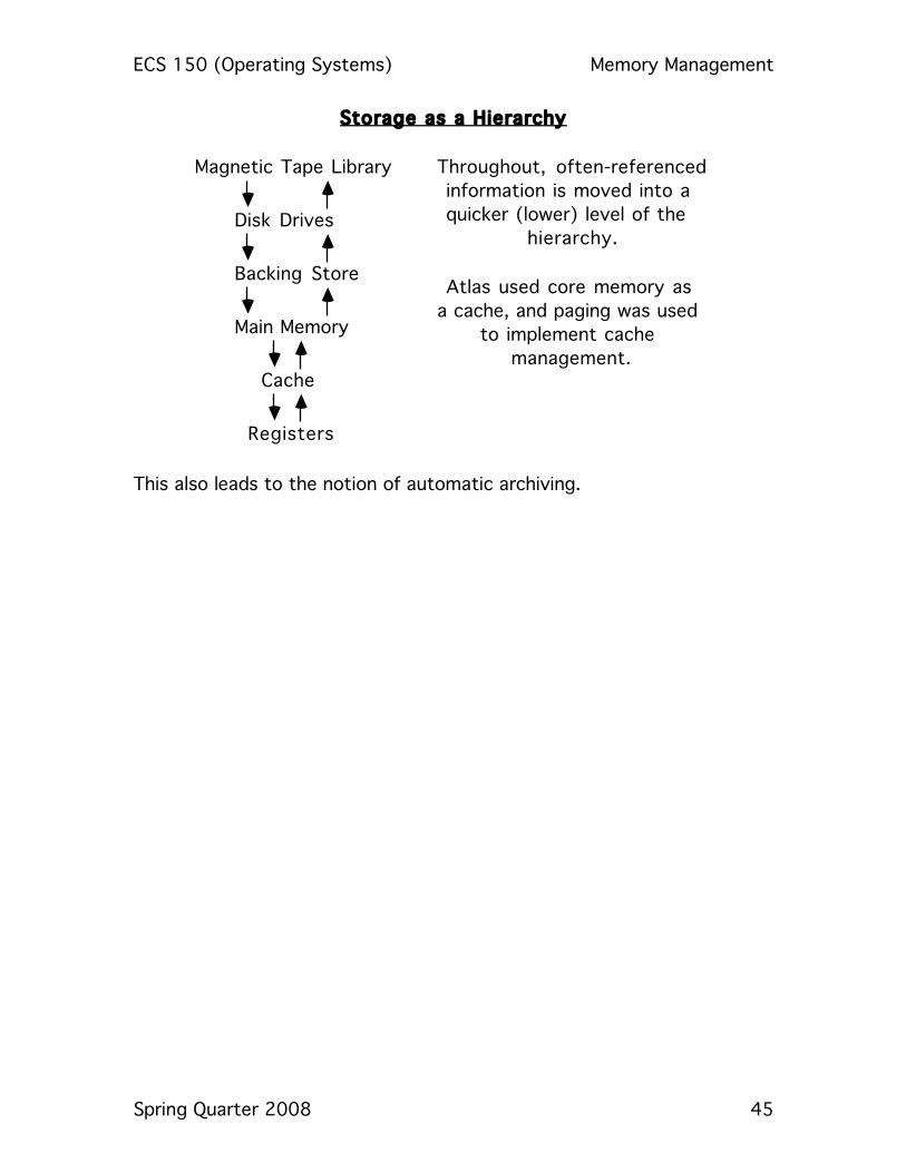
Storage as a Hierarchy
Magnetic Tape Library
Disk Drives
Backing Store
Main Memory
Cache
Registers
Throughout, often-referenced
information is moved into a
quicker (lower) level of the
hierarchy.
Atlas used core memory as
a cache, and paging was used
to implement cache
management.
This also leads to the notion of automatic archiving.