meoclass-45prep-140316110130-phpapp01.pdf
TRANSCRIPT
Hanif Dewan.IMA.MEO Class- 4&5 Prep. Course-September, 2013. 1
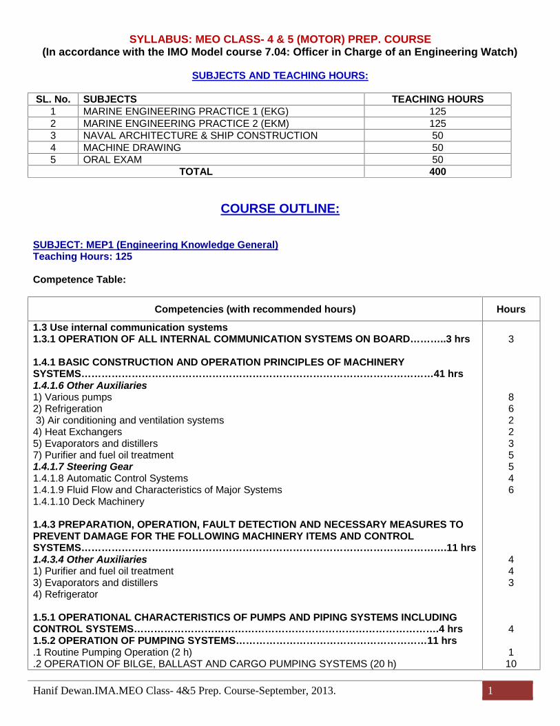
SYLLABUS: MEO CLASS- 4 & 5 (MOTOR) PREP. COURSE(In accordance with the IMO Model course 7.04: Officer in Charge of an Engineering Watch)
SUBJECTS AND TEACHING HOURS:
SL. No. SUBJECTS TEACHING HOURS1 MARINE ENGINEERING PRACTICE 1 (EKG) 1252 MARINE ENGINEERING PRACTICE 2 (EKM) 1253 NAVAL ARCHITECTURE & SHIP CONSTRUCTION 504 MACHINE DRAWING 505 ORAL EXAM 50
TOTAL 400
COURSE OUTLINE:
SUBJECT: MEP1 (Engineering Knowledge General)Teaching Hours: 125
Competence Table:
Competencies (with recommended hours) Hours
1.3 Use internal communication systems1.3.1 OPERATION OF ALL INTERNAL COMMUNICATION SYSTEMS ON BOARD………..3 hrs
1.4.1 BASIC CONSTRUCTION AND OPERATION PRINCIPLES OF MACHINERYSYSTEMS……………………………………………………………………………………………41 hrs1.4.1.6 Other Auxiliaries1) Various pumps2) Refrigeration3) Air conditioning and ventilation systems
4) Heat Exchangers5) Evaporators and distillers7) Purifier and fuel oil treatment1.4.1.7 Steering Gear1.4.1.8 Automatic Control Systems1.4.1.9 Fluid Flow and Characteristics of Major Systems1.4.1.10 Deck Machinery
1.4.3 PREPARATION, OPERATION, FAULT DETECTION AND NECESSARY MEASURES TOPREVENT DAMAGE FOR THE FOLLOWING MACHINERY ITEMS AND CONTROLSYSTEMS……………………………………………………………………………………………….11 hrs1.4.3.4 Other Auxiliaries1) Purifier and fuel oil treatment3) Evaporators and distillers4) Refrigerator
1.5.1 OPERATIONAL CHARACTERISTICS OF PUMPS AND PIPING SYSTEMS INCLUDINGCONTROL SYSTEMS……………………………………………………………………………….4 hrs1.5.2 OPERATION OF PUMPING SYSTEMS…………………………………………………11 hrs.1 Routine Pumping Operation (2 h).2 OPERATION OF BILGE, BALLAST AND CARGO PUMPING SYSTEMS (20 h)
3
862235546
443
4
110
Hanif Dewan.IMA.MEO Class- 4&5 Prep. Course-September, 2013. 2
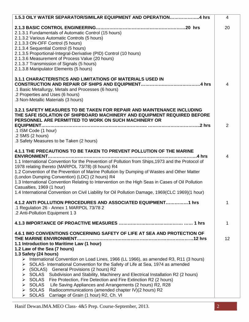
1.5.3 OILY WATER SEPARATOR/SIMILAR EQUIPMENT AND OPERATION………………..4 hrs
2.1.3 BASIC CONTROL ENGINEERING……………………………………………………20 hrs2.1.3.1 Fundamentals of Automatic Control (15 hours)2.1.3.2 Various Automatic Controls (5 hours)2.1.3.3 ON-OFF Control (5 hours)2.1.3.4 Sequential Control (5 hours)2.1.3.5 Proportional-Integral-Derivative (PID) Control (10 hours)2.1.3.6 Measurement of Process Value (20 hours)2.1.3.7 Transmission of Signals (5 hours)2.1.3.8 Manipulator Elements (5 hours)
3.1.1 CHARACTERISTICS AND LIMITATIONS OF MATERIALS USED INCONSTRUCTION AND REPAIR OF SHIPS AND EQUIPMENT…………….……………………4 hrs.1 Basic Metallurgy, Metals and Processes (6 hours).2 Properties and Uses (6 hours).3 Non-Metallic Materials (3 hours)
3.2.1 SAFETY MEASURES TO BE TAKEN FOR REPAIR AND MAINTENANCE INCLUDINGTHE SAFE ISOLATION OF SHIPBOARD MACHINERY AND EQUIPMENT REQUIRED BEFOREPERSONNEL ARE PERMITTED TO WORK ON SUCH MACHINERY OREQUIPMENT…………………………………………………………….. ……………………………..2 hrs.1 ISM Code (1 hour).2 SMS (2 hours).3 Safety Measures to be Taken (2 hours)
4.1.1 THE PRECAUTIONS TO BE TAKEN TO PREVENT POLLUTION OF THE MARINEENVIRONMENT……………………………………………………………………………………….4 hrs1.1 International Convention for the Prevention of Pollution from Ships,1973 and the Protocol of1978 relating thereto (MARPOL 73/78) (8 hours) R41.2 Convention of the Prevention of Marine Pollution by Dumping of Wastes and Other Matter(London Dumping Convention) (LDC) (2 hours) R41.3 International Convention Relating to Intervention on the High Seas in Cases of Oil PollutionCasualties, 1969 (1 hour)1.4 International Convention on Civil Liability for Oil Pollution Damage, 1969(CLC 1969)(1 hour)
4.1.2 ANTI POLLUTION PROCEDURES AND ASSOCIATED EQUIPMENT……………1 hrs.1 Regulation 26 - Annex 1 MARPOL 73/78 2.2 Anti-Pollution Equipment 1 3
4.1.3 IMPORTANCE OF PROACTIVE MEASURES ……………………………………. …… 1 hrs
4.6.1 IMO CONVENTIONS CONCERNING SAFETY OF LIFE AT SEA AND PROTECTION OFTHE MARINE ENVIRONMENT……………………………………………………………………12 hrs1.1 Introduction to Maritime Law (1 hour)1.2 Law of the Sea (7 hours)1.3 Safety (24 hours) International Convention on Load Lines, 1966 (LL 1966), as amended R3, R11 (3 hours) SOLAS- International Convention for the Safety of Life at Sea, 1974 as amended (SOLAS)-General Provisions (2 hours) R2 SOLAS-Subdivision and Stability, Machinery and Electrical Installation R2 (2 hours) SOLAS-Fire Protection, Fire Detection and Fire Extinction R2 (2 hours) SOLAS-Life Saving Appliances and Arrangements (2 hours) R2, R28 SOLAS-Radiocommunications (amended chapter IV)(2 hours) R2 SOLAS-Carriage of Grain (1 hour) R2, Ch. VI
4
20
4
2
4
1
1
12

Hanif Dewan.IMA.MEO Class- 4&5 Prep. Course-September, 2013. 3
SOLAS-Carriage of Dangerous Goods (1 hour) R2 The International Safety Management (ISM) Code R29 International Convention on Standards of Training, Certification and Watchkeeping for
Seafarers, 2010 (STCW) (2 hours) R1 International Convention for the Control and Management of Ship's Ballast Water and
Sediments, 2004
4.7 APPLICATION OF LEADERSHIP AND TEAMWORKING SKILLS………………………….7 hrs.1 Introduction to Management 2.2 Related Conventions and National Legislations 2.3 Applies Task and Workload Management 10.4 Applies Effective Resource Management and Decision Making 10
7
Total 125
SUBJECT: MEP2 (Marine Engineering Knowledge Motor)Teaching Hours: 125
Competence Table:
Competencies (with recommended hours) Hours
1.1 MAINTAIN A SAFE ENGINEERING WATCH …………………………………………….14 HRS1.1.1 Thorough knowledge of principles to be observed in keeping an engineering watch1.1.2 safety and emergency procedures1.1.3 safety precautions to be observed during a watch and immediate actions to be taken1.1.4 engine-room resource management
1.4.1 BASIC CONSTRUCTION AND OPERATION PRINCIPLES OF MACHINERY SYSTEMS1.4.1.1 Marine Diesel Engine……………………………………………………………………35 HRS3) Diesel engine fuel atomization and combustion4) Engine types5) Engine principles6) Basic Constructiona) Large-bore (two-stroke) engine detailsb) Medium-speed & high-speed (4-stroke) diesel engines1.4.1.4 Marine Boiler………….…………………………………………………………………….15 HRS1) Steam boiler fuel atomization and combustion2) Marine boiler fundamentals3) Marine boiler construction4) Marine boiler mountings and steam distribution1.4.1.5 Shafting Installations and Propeller…………………………………………………10 HRS1) Shafting installations2) Propellers1.4.1.6 Other Auxiliaries6) Air compressor and system principles (15 hours)……………………………………….10 HRSa) Air Compressorsb) Air compressors and system principles
1.4.2 SAFETY AND EMERGENCY PROCEDURES FOR OPERATION OF PROPULSION PLANTMACHINERY INCLUDING CONTROL SYSTEMS……………………………………………13 HRS1.4.2.1 Main Engine Auto-slow down and Shut down1.4.2.2 Main Boiler Auto-shut down1.4.2.3 Power Failure (Blackout)1.4.3 PREPARATION, OPERATION, FAULT DETECTION AND NECESSARY MEASURES TOPREVENT DAMAGE FOR THE FOLLOWING MACHINERY ITEMS AND CONTROL
3443
735
1010
4335
55
73
553
Hanif Dewan.IMA.MEO Class- 4&5 Prep. Course-September, 2013. 4
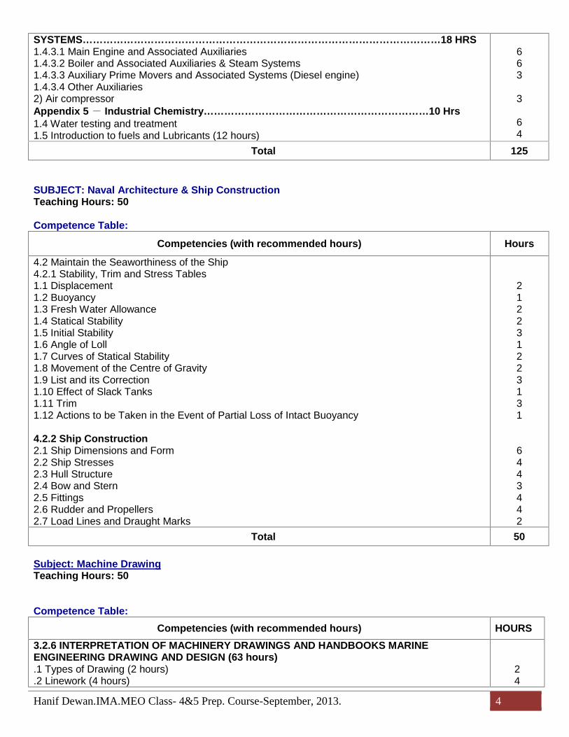
SYSTEMS……………………………………………………………………………………………18 HRS1.4.3.1 Main Engine and Associated Auxiliaries1.4.3.2 Boiler and Associated Auxiliaries & Steam Systems1.4.3.3 Auxiliary Prime Movers and Associated Systems (Diesel engine)1.4.3.4 Other Auxiliaries2) Air compressorAppendix 5- Industrial Chemistry…………………………………………………………10 Hrs1.4 Water testing and treatment1.5 Introduction to fuels and Lubricants (12 hours)
663
3
64
Total 125
SUBJECT: Naval Architecture & Ship ConstructionTeaching Hours: 50
Competence Table:
Competencies (with recommended hours) Hours
4.2 Maintain the Seaworthiness of the Ship4.2.1 Stability, Trim and Stress Tables1.1 Displacement1.2 Buoyancy1.3 Fresh Water Allowance1.4 Statical Stability1.5 Initial Stability1.6 Angle of Loll1.7 Curves of Statical Stability1.8 Movement of the Centre of Gravity1.9 List and its Correction1.10 Effect of Slack Tanks1.11 Trim1.12 Actions to be Taken in the Event of Partial Loss of Intact Buoyancy
4.2.2 Ship Construction2.1 Ship Dimensions and Form2.2 Ship Stresses2.3 Hull Structure2.4 Bow and Stern2.5 Fittings2.6 Rudder and Propellers2.7 Load Lines and Draught Marks
212231223131
6443442
Total 50
Subject: Machine DrawingTeaching Hours: 50
Competence Table:Competencies (with recommended hours) HOURS
3.2.6 INTERPRETATION OF MACHINERY DRAWINGS AND HANDBOOKS MARINEENGINEERING DRAWING AND DESIGN (63 hours).1 Types of Drawing (2 hours).2 Linework (4 hours)
24

Hanif Dewan.IMA.MEO Class- 4&5 Prep. Course-September, 2013. 5
.3 Pictorial Projection (4 hours)
.4 Development (4 hours)
.5 Dimensioning (5 hours)
.6 Geometrical Tolerancing (2 hours)
.7 Limits and Fits (2 hours)
.8 Engineering Drawing Practice & Assembly Drawing1) AIR INLET VALVE2) AUTOMATIC VALVE3) REDUCING VALVE4) RUDDER CARRIER BEARING5) STARTING AIR VALVE
3.2.7 THE INTERPRETATION OF PIPING, HYDRAULIC AND PNEUMATIC DIAGRAMS (5 hrs)
44522
22
5Total 50
Subject: MEO CLASS- 4&5 (MOTOR) ORAL EXAMTeaching Hours: 50
Competence Table:
Competencies (with recommended hours) HOURS
1. ENGINE ROOM WATCH KEEPING2. RUNNING & MAINTENANCE OF VARIOUS MACHINERIES:3. AIR COMPRESSORS AND SYSTEM PRINCIPLES4. GENERATOR ALTERNATORS:5. FIRE & SAFETY6. REFRIGERATION7. MARINE DIESEL ENGINE SAFE & EFFICIENT OPERATION & MAINTENANCE MARINE
DIESEL8. MARINE DIESEL ENGINE9. CHIEF ENGINEER’S ADMINISTRATIONAL DUTIES & FORMALITIES10. KNOWLEDGE REGARDING DRY DOCKING & SAFTY SURVEY11. BANGLADESH SHIPPING ACTS12. MARINE LAWS
2553537
53336
Total 50

Hanif Dewan.IMA.CLASS-4&5 (MOTOR) PREP. COURSE 1
SUBJECTS DETAILS
SUBJECT: MEP1 (Engineering Knowledge General)Teaching Hours: 125
Course Outline:Competence Table:
Competencies (with recommended hours) Hours
1.3 Use internal communication systems1.3.1 OPERATION OF ALL INTERNAL COMMUNICATION SYSTEMS ON BOARD………..3 hrs
1.4.1 BASIC CONSTRUCTION AND OPERATION PRINCIPLES OF MACHINERYSYSTEMS……………………………………………………………………………………………41 hrs1.4.1.6 Other Auxiliaries1) Various pumps (20 hours)2) Refrigeration (26 hours)3) Air conditioning and ventilation systems (5 hours)
4) Heat Exchangers (10 hours) R15) Evaporators and distillers (15 hours) R17) Purifier and fuel oil treatment (10 hours)1.4.1.7 Steering Gear1.4.1.8 Automatic Control Systems (20 h)1.4.1.9 Fluid Flow and Characteristics of Major Systems (15 h)1.4.1.10 Deck Machinery (10 h)
1.4.3 PREPARATION, OPERATION, FAULT DETECTION AND NECESSARY MEASURES TOPREVENT DAMAGE FOR THE FOLLOWING MACHINERY ITEMS AND CONTROLSYSTEMS……………………………………………………………………………………………….11 hrs1.4.3.4 Other Auxiliaries1) Purifier and fuel oil treatment (8 hours) R13) Evaporators and distillers (10 hours) R14) Refrigerator (8 hours)
1.5.1 OPERATIONAL CHARACTERISTICS OF PUMPS AND PIPING SYSTEMS INCLUDINGCONTROL SYSTEMS………………………………………………………………………………. 4 hrs1.5.2 OPERATION OF PUMPING SYSTEMS……………………………………………………11 hrs.1 Routine Pumping Operation (2 h).2 OPERATION OF BILGE, BALLAST AND CARGO PUMPING SYSTEMS (20 h)1.5.3 OILY WATER SEPARATOR/SIMILAR EQUIPMENT AND OPERATION………………...4 hrs
2.1.3 BASIC CONTROL ENGINEERING…………………………………………………………20 hrs2.1.3.1 Fundamentals of Automatic Control (15 hours)2.1.3.2 Various Automatic Controls (5 hours)2.1.3.3 ON-OFF Control (5 hours)2.1.3.4 Sequential Control (5 hours)2.1.3.5 Proportional-Integral-Derivative (PID) Control (10 hours)2.1.3.6 Measurement of Process Value (20 hours)
3
862235546
443
4
1104
20
Hanif Dewan.IMA.CLASS-4&5 (MOTOR) PREP. COURSE 2
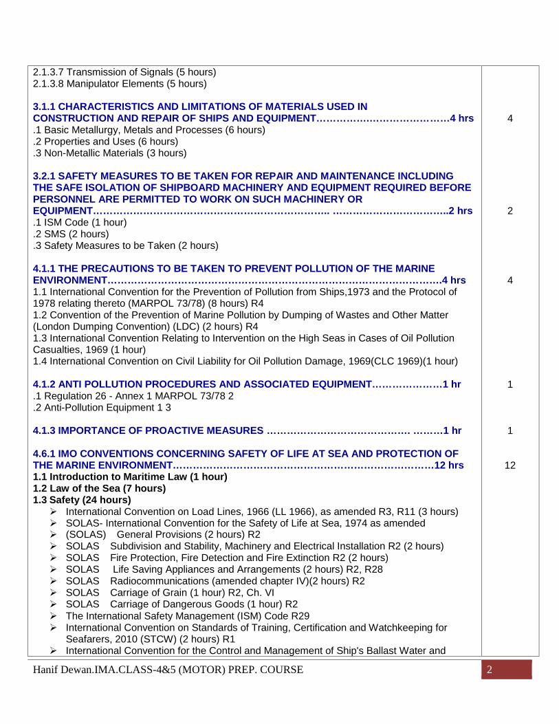
2.1.3.7 Transmission of Signals (5 hours)2.1.3.8 Manipulator Elements (5 hours)
3.1.1 CHARACTERISTICS AND LIMITATIONS OF MATERIALS USED INCONSTRUCTION AND REPAIR OF SHIPS AND EQUIPMENT…………….……………………4 hrs.1 Basic Metallurgy, Metals and Processes (6 hours).2 Properties and Uses (6 hours).3 Non-Metallic Materials (3 hours)
3.2.1 SAFETY MEASURES TO BE TAKEN FOR REPAIR AND MAINTENANCE INCLUDINGTHE SAFE ISOLATION OF SHIPBOARD MACHINERY AND EQUIPMENT REQUIRED BEFOREPERSONNEL ARE PERMITTED TO WORK ON SUCH MACHINERY OREQUIPMENT…………………………………………………………….. ……………………………..2 hrs.1 ISM Code (1 hour).2 SMS (2 hours).3 Safety Measures to be Taken (2 hours)
4.1.1 THE PRECAUTIONS TO BE TAKEN TO PREVENT POLLUTION OF THE MARINEENVIRONMENT……………………………………………………………………………………….4 hrs1.1 International Convention for the Prevention of Pollution from Ships,1973 and the Protocol of1978 relating thereto (MARPOL 73/78) (8 hours) R41.2 Convention of the Prevention of Marine Pollution by Dumping of Wastes and Other Matter(London Dumping Convention) (LDC) (2 hours) R41.3 International Convention Relating to Intervention on the High Seas in Cases of Oil PollutionCasualties, 1969 (1 hour)1.4 International Convention on Civil Liability for Oil Pollution Damage, 1969(CLC 1969)(1 hour)
4.1.2 ANTI POLLUTION PROCEDURES AND ASSOCIATED EQUIPMENT…………………1 hr.1 Regulation 26 - Annex 1 MARPOL 73/78 2.2 Anti-Pollution Equipment 1 3
4.1.3 IMPORTANCE OF PROACTIVE MEASURES ……………………………………. ………1 hr
4.6.1 IMO CONVENTIONS CONCERNING SAFETY OF LIFE AT SEA AND PROTECTION OFTHE MARINE ENVIRONMENT……………………………………………………………………12 hrs1.1 Introduction to Maritime Law (1 hour)1.2 Law of the Sea (7 hours)1.3 Safety (24 hours) International Convention on Load Lines, 1966 (LL 1966), as amended R3, R11 (3 hours) SOLAS- International Convention for the Safety of Life at Sea, 1974 as amended (SOLAS)-General Provisions (2 hours) R2 SOLAS-Subdivision and Stability, Machinery and Electrical Installation R2 (2 hours) SOLAS-Fire Protection, Fire Detection and Fire Extinction R2 (2 hours) SOLAS-Life Saving Appliances and Arrangements (2 hours) R2, R28 SOLAS-Radiocommunications (amended chapter IV)(2 hours) R2 SOLAS-Carriage of Grain (1 hour) R2, Ch. VI SOLAS-Carriage of Dangerous Goods (1 hour) R2 The International Safety Management (ISM) Code R29 International Convention on Standards of Training, Certification and Watchkeeping for
Seafarers, 2010 (STCW) (2 hours) R1 International Convention for the Control and Management of Ship's Ballast Water and
4
2
4
1
1
12

Hanif Dewan.IMA.CLASS-4&5 (MOTOR) PREP. COURSE 3
Sediments, 2004
4.7 APPLICATION OF LEADERSHIP AND TEAMWORKING SKILLS………………………….7 hrs.1 Introduction to Management 2.2 Related Conventions and National Legislations 2.3 Applies Task and Workload Management 10.4 Applies Effective Resource Management and Decision Making 10
7
Total 125
COMPETENCE DETAILS:
Competencycode Learning Objectives Hours
1.31.3.1
1.4.1.6
1.3 Use internal communication systems1.3.1 OPERATION OF ALL INTERNAL COMMUNICATION SYSTEMS ON BOARD(5 hours)– States the importance of:– communicating effectively in all circumstances;– orders, instructions, reports and exchange of information being clear, accurateand concise;– using accepted marine terminology, and proper methods are employed;– chief or second Engineer being kept informed as required; and– the bridge being informed and consulted as required.
AUXILIARY MACHINERIES
1.4.1.6 Other Auxiliaries
1) Various pumps (20 hours)a) Principles of pumping operationb) Types of pump (15 hours) R1– Names the types of pump generally used on ships and the purposes for which theyare normally used– Explains the basic action of a displacement pump– Explains the necessity for a relief valve to be fitted in the discharge of anydisplacement pump– States that when a pump is handling oil or other hazardous material any dischargefromthe relief valve must be contained within the pumping system– Describes, with the aid of diagrams, how a reciprocating displacement pump works– Explains the purpose of an air vessel fitted to the discharge– Describes the characteristics of a reciprocating pump, referring to:– suction lift– priming– discharge pressure– vapour, or gas, in the fluid being pumped
Hanif Dewan.IMA.CLASS-4&5 (MOTOR) PREP. COURSE 4
1.4.1.7
1.4.2.4
1.4.1.91.4.1.10
– Explains the principle of rotary displacement pumps– Sketches a single line diagram to show the principle parts of:– a gear pump– a rotary vane pump– a screw-displacement pump– Describes the principles of operation of an axial-flow pump– Describes the type of duty best suited to an axial-flow pump– Explains the principles of a centrifugal pump, referring of the purpose of:– the impeller– the diffuser or volute– Makes a single line sketch of a vertical single-entry centrifugal pump– Explains what is meant by a 'single-entry' and a 'double entry' impeller– Describes the arrangement of a vertical multi-stage single-entry centrifugal– Explains the purpose of a diffuser– Describes the characteristics of a centrifugal pump, referring to:– suction lift– priming– discharge pressure– vapour or gas in the fluid being pumped– Explains why and when priming and/or air extraction is necessary and makes singlelinesketches of:– a reciprocating air pump– a water-ring air pump– Makes a single line sketch of a central priming system and explains its advantage– Explains the principle of an ejector
2) Refrigeration (26 hours)a) Marine refrigeration cycle (6 hours) R1b) Principles of refrigeration (8 hours) R1c) Refrigerating compressors (2 hour) R1d) Refrigerating system components (4 hours) R1e) Refrigerating system brines (4 hours)f) Cold storage spaces (2 hour)3) Air conditioning and ventilation systems (5 hours)4) Heat Exchangers (10 hours) R15) Evaporators and distillers (15 hours) R17) Purifier and fuel oil treatment (10 hours)
1.4.1.7 Steering Gear (20 hours)1) Steering gear principles (10 hours) R12) Steering gear electrical control (2 hour)– Describes the principles of operation of an electrical control system3) Hydraulic power-operated rudder systems (4 hours)4) Hydraulic power rotary pumps (4 hours)
1.4.2.4 Emergency Procedures for Other Equipment/Installations1) Emergency steering (1 hour) R1
1.4.1.9 Fluid Flow and Characteristics of Major Systems (15 hours)1.4.1.10 Deck Machinery (10 hours)
Hanif Dewan.IMA.CLASS-4&5 (MOTOR) PREP. COURSE 5
1.4.3
1.4.3.4
1) Windlass/mooring winch2) Winch3) Boat winch
1.4.3 PREPARATION, OPERATION, FAULT DETECTION AND NECESSARYMEASURES TO PREVENT DAMAGE FOR THE FOLLOWING MACHINERYITEMS AND CONTROL SYSTEMS1.4.3.4 Other Auxiliaries (26 hours)1) Purifier and fuel oil treatment (8 hours) R1– States sequence of discharging sludge– States why oil purifier needs following data concerning oil:
temperature quantity of flow density/specific gravity
– Explains the function of gravity disk– Explains the function of low and high pressure water– Describes sludge discharging mechanism of an oil purifier– Explains the difference between purifying and clarifying– Explains precautions for starting purifier and checking points to ensure a goodworking order
3) Evaporators and distillers (10 hours) R1– Describes the need for starting fresh water generator and the limitation of keeping itsrunning– Explains the outlines of starting procedures in accordance with typical type of freshwater generators(Control of water density and scale)– Explains how the formation of scale on the heating surfaces of coils, tubes and otherheat-transfer elements is controlled– States the limiting pressure and temperature in the shell in order to control theformation of scale– Describes the type of scale deposited on the heating surfaces– Explains how the scale described in the above objective is removed(Distillation) R1– Defines the term distillation as used in marine engineering practice– Describes the function of a distiller as that of condensing fresh water from thevapourproduced in an evaporator(Drinking water) R1
– Describes the quality necessary if the water being produced by a distiller is to beused for human consumption– States that if, during the evaporation process, a temperature of 75℃ is not achieved,chemical agents must be added to the water to destroy any harmful bacteria whichmay be present
4) Refrigerator (8 hours)– States the preparation and precautions for starting a refrigerator– States precautions and checking points on a refrigerator while its running– States what malfunctions/troubles likely occur in refrigerators– Describes the effect of variations in seawater temperature on the running of arefrigerating system
Hanif Dewan.IMA.CLASS-4&5 (MOTOR) PREP. COURSE 6
1.5.1
1.5.21.5.2.1
1.5.2.2
– Describes the effect in refrigeration unit of air, moisture and oil– Explains how to charge refrigerant into a refrigerator and vice versa– Explains how to charge lubricating oil into a refrigerator and vice versa– Explains how to remove air from a refrigerator unit– States how to inspect leaking of refrigerant
1.5.1 OPERATIONAL CHARACTERISTICS OF PUMPS AND PIPING SYSTEMSINCLUDING CONTROL SYSTEMS (10 hours) R1– States that, if there is no positive head at the inlet to a centrifugal pump, a primingdevice must be used– Describes or performs the correct procedure for starting up and stopping:– positive-displacement pumps– axial-flow pumps– centrifugal pumpsmaking reference to:– suction valves– discharge valves– priming
1.5.2 OPERATION OF PUMPING SYSTEMS (22 hours)1.5.2.1 Routine Pumping Operations (2 hours)– States the need to understand the pipe lines constructing pumping systems to bedaily used in order to maintain the normal operation of the plant– States that the status of valves concerned in both manual and automatic pumpingsystems must be periodically checked– States that any operation of pumping systems should be recorded in such a routineworks record book
1.5.2.2 Operation of Bilge, Ballast and Cargo Pumping Systems (20 hours)(Bilge) R1– Sketches a diagrammatic arrangement of a bilge pumping system, including theconnections to other pumps– Describes the purpose, siting and common principal connections of an emergencybilgesuction– Describes the principle features of an emergency bilge pump(Ballast)– Explains the purpose of a ballast pumping system– Explains the fittings necessary when a space may be used for:– ballast or dry cargo– ballast or oil– Sketches a diagrammatic arrangement of a ballast system(Fresh water and Seawater)– Lists the main uses of fresh water and seawater– Describes a domestic fresh-water pumping system, explaining how:
the water pressure is maintained the pump is started and stopped the water is heated
– Describes a domestic seawater pumping system– Describes the treatment necessary for water produced by evaporators for humanconsumption

Hanif Dewan.IMA.CLASS-4&5 (MOTOR) PREP. COURSE 7
1.5.3
(Hydraulic system)– Lists the machinery which might be controlled or driven by hydraulic motors– Describes a hydraulic system– Describes the properties of hydraulic fluid– Explains the care necessary when topping up the fluid from a hydraulic system(Sewage system)– Explains what is meant by a coliform count in sewage systems– Explains what is meant by a sewage-retention system– Explains the purpose of a sewage comminutor– Describes the principles of a biological sewage treatment plant– States that the effluent from a sewage plant must not be discharged in certainspecifiedareas and that permission to discharge sewage must be obtained from the officer incharge of a navigational watch(Incinerator)– Explains briefly the purpose and operation of an incinerator for the disposal of:– sludge– refuse(Fire main) R1– Explains, using a single line sketch, how a fire main is supplied with water, includingthecross connections with other pumps– States that the minimum number of independently driven fire pumps is laid down byinternational law– States that, where installed, an independent fire pump, driven by a diesel engine,shouldbe capable of being readily and repeatedly started– Explains the purpose of the isolating valve in the machinery space fire-pumpdeliverymain(Fuel oil)– States that fuel oil is stored in double-bottom tanks, wing tanks or special deep tanks– Describes the venting arrangements for fuel tanks– States that the two properties which indicate fluidity are viscosity and pour point– Explains how fluidity of the fuel is achieved when fuel is to be transferred– States the minimum closed flashpoint of marine fuels– States the maximum temperature to which fuel oil may be raised for transfer andwhenstored in a settling tank– States that: oil leaks should be remedied as soon as possible oil dips should be collected in a container, which must be emptied very
frequently cleanliness is essential Lists the precautions to be taken to avoid spillage when bunkering
1.5.3 OILY WATER SEPARATOR/SIMILAR EQUIPMENT REQUIREMENTS ANDOPERATION (8 hours) R1– Describes the requirements necessary for oily water separators/similar equipment– Describes the oil separation principles of oily water separators/similar equipment– Describes the components constructing oily water separators/similar equipment– Explains how to prevent oil being mixed into discharging bilge when oil content
Hanif Dewan.IMA.CLASS-4&5 (MOTOR) PREP. COURSE 8
3.1.1
3.1.1.1
3.1.1.2
3.1.1.3
exceeds15 ppm– States that pollution of the sea is an offence under international law– States that the dumping of oil or oil-water mixtures is strictly prohibited– States that the effluent should be further filtered to give an output containing amaximumof 15 p.p.m. of oil under all inlet conditions– Describes, with the aid of a single line sketch, the operation of an automatic three-stage oily-water separator/similar equipment– Lists the information which must be entered in the Oil Record Book when pumpingout Bilges
MATERIALS:
3.1.1 CHARACTERISTICS AND LIMITATIONS OF MATERIALS USED INCONSTRUCTION AND REPAIR OF SHIPS AND EQUIPMENT (15 hours)3.1.1.1 Basic Metallurgy, Metals and Processes (6 hours) R1– Describes in simple terms the production of pig iron from iron ore– Explains the principal differences between sand casting, die casting, centrifugalcasting,forgings, cold working and hot-rolled plate, bars and other sections– States the normal range of carbon content in mild steel, tool steel, cast steel andcast iron– States the purpose of the alloying elements nickel, chromium and molybdenum insteelsused in marine engineering3.1.1.2 Properties and Uses (6 hours) R1– Explains in simple terms what influences the choice of material for a marineengineeringcomponent– Describe in simple terms what is meant by the following mechanical properties:
elasticity brittleness hardness strength toughness ductility malleability plasticity
– Explains what is meant by low-, medium-and high-carbon steels– Compares the tensile strength, ductility and hardness of low-, medium-and high-carbon steels3.1.1.3 Non-Metallic Materials (3 hours) R1– Explains the reasons for using the following fillers in polymers:– glass fibre– mica– States that polymers can be plastic, rigid, semi-rigid or elastomeric– States the properties and limitations of polymers– Lists polymers and other non-metallic materials in common use– States applications of polymers and other non-metallic materials on board ship

Hanif Dewan.IMA.CLASS-4&5 (MOTOR) PREP. COURSE 9
2.1.3
2.1.3.1
2.1.3.1
2.1.3.3
2.1.3.4
2.1.3.5
2.1.3.6
CONTROL ENGINEERING
2.1.3 BASIC CONTROL ENGINEERING (70 hours)
Required performance:2.1.3.1 Fundamentals of Automatic Control (15 hours)– Defines an automatic control and states its purpose– Describes what devices/equipment construct control systems and their role/functions– Relates sensing unit, controller, controlled variable, manipulating variable andcontrolled object to each of them in the control system– Describes what sort of devices are included in the sensing unit– Describes variety of controllers such as electronic (PID, PLC, computer) controllerand pneumatic controller– Defines setting value, input value, deviation and output value/controlled variable inthe controller2.1.3.2 Various Automatic Controls (5 hours)– Classifies systematically automatic controls in terms of control methodologies–– Explains briefly feedback control and feedforward control– Describes briefly ON-OFF control, sequential control, PID control and programcontrol2.1.3.3 ON-OFF Control (5 hours)– Explains what ON-OFF control means– Explains the characteristics of ON-OFF control– Explains how ON-OFF control is utilized2.1.3.4 Sequential Control (5 hours)– Explains what a sequential control means– Explains the characteristics of a sequential control– Explains how a sequential control is utilized2.1.3.5 Proportional-Integral-Derivative (PID) Control (10 hours)– Explains the principles/theory of PID control– Explains how P, I and D actions can be electrically/pneumatically available showingsimple electronic circuits and pneumatic diagrams– States that PID control is classical control methodology but even now, it is still firmbasis for controlling any physical/process value– Explains how P, I, and D parameters for optimal control can be determined
2.1.3.6 Measurement of Process Value (20 hours)1) Temperature(Mechanical)– States that it is common practice to call the measuring instrument for temperatures– above 500℃ a pyrometer– below 500℃ a thermometer– States the temperature range for which mercury is used– Describes the principal features of a bimetallic thermometer(Electrical)– States that the range and accuracy varies according to the material used in thedetecting element– Sketches and describes a resistance-type measuring instrument based on theWheatstone bridge– Describes the characteristics of a thermistor and the conditions for which it issuitable
Hanif Dewan.IMA.CLASS-4&5 (MOTOR) PREP. COURSE 10
2.1.3.7
2) Pressure– Describes the principle features of, and compares, the following:
manometerssimple waterwide-cistern or well inclined-tubemercurypressure gaugesBourdondiaphragm-sealed gaugeSchaffer twin-bellows differential-pressure cellstrain gauge
–– States that calibration and testing are normally performed by specialists3) Level(Direct Methods)– Describes the principle of a float-operated level-measuring device– Describes the principle of a probe element4) Flow– Explains the difference between a quantity metre and a rate-of-flow-flow metre– Explains that a quantity metre is basically a rate-of-flow metre combined with anintegrator– Describes the function of the two elements of a flow metre5) General Measurement of Processes– Explains the principles of a tachometer– Explains the principles of A.C. and D.C. electric tachometers– Explains the principal features of a viscometer– Describes the application of a photoelectric cell to:
an oil-in-watera smoke-density detectoran oil-mist detectora flame detector
– Describes the common types of fire detector– Describes the principal features of: an explosive-gas detector a vibration monitor an oxygen analyser a CO2 analyser a relative humidity metre salinity measurement a dissolved-oxygen metre a pH metre
2.1.3.7 Transmission of Signals (5 hours)1) Transmitters– Describes the function of a transducer2) Controlling Elements(Pneumatic)– Describes the flapper and nozzle arrangement– Explains what is meant by negative feedback and by positive feedback(Electrical)
– Uses a Wheatstone bridge used as a transducer
Hanif Dewan.IMA.CLASS-4&5 (MOTOR) PREP. COURSE 11
2.1.3.8
3.2.1
3.2.1.1
3.2.1.2
3.2.1.3
– Describes the principles of a variable-inductance
(Receivers)– Describes the principal features of:– a pneumatic receiver integrator– a potentiometric pen recorder
2.1.3.8 Manipulator Elements (5 hours)1) Pneumatic– States that the final controller might be operated pneumatically, hydraulically orelectrically– Sketches a diaphragm-operated control valve– Describes the characteristics of the motor element and the correcting element in theabove objective– Explains what is meant by ''turn-down ratio"– Describes the conditions which may dictate the need for a positioner– Describes the principal features of a positioner2) Electrical Servomotors– Describes a dc servomotor and explains how it varies from the common motor– Explains the problems of using a three-phase ac machine as a servomotor– Describes the applications of a two-phase ac servomotor, explaining how itscharacteristics can be varied3) Hydraulic Servomotor– Describes the principles of a swash plate pump– Explains the advantage of using high pressures– Explains the applications of a hydraulic ram servomotor
MARINE LAW & REGULATION
3.2.1 SAFETY MEASURES TO BE TAKEN FOR REPAIR AND MAINTENANCEINCLUDING THE SAFE ISOLATION OF SHIPBOARD MACHINERY ANDEQUIPMENT REQUIRED BEFORE PERSONNEL ARE PERMITTED TO WORKON SUCH MACHINERY OR EQUIPMENT
3.2.1.1 ISM Code (1 hour) R5– Explains the outline of ISM Code (International Safety Management) including thebackground and process of establishment3.2.1.2 SMS (2 hours)– Explains briefly how a SMS (Safety Management System) should be establishedandwhat sorts of documents are included– Lists documents, checklists and others for safety measures for fabrication and repairandexplains their specific purposes3.2.1.3 Safety Measures to be Taken (2 hours) R1– States that safety measures to be taken for repair and maintenance can be identifiedthrough proper risk assessment– States that safety measures based on SMS should be applied to identified risks– Explains that tool box talks prior to repair and maintenance are effective for takingnecessary safety measures
Hanif Dewan.IMA.CLASS-4&5 (MOTOR) PREP. COURSE 12
4.6.1
– Explains that safety measures include use of protective equipment, preparation ofproperlighting, antislipping measures, preparation of safety procedures, setting up a safetybarrier, preparation of a safe working platform, mechanical/electrical isolation ofmachinery to be repaired/maintained, prior checks based on SMS– Explains that particular safety measures in accordance with machinery feature maybenecessary
4.6.1 IMO CONVENTIONS CONCERNING SAFETY OF LIFE AT SEA ANDPROTECTION OF THE MARINE ENVIRONMENT1.1 Introduction to Maritime Law (1 hour)-lists the main originators of international conventions concerned with maritime laware:-International Maritime Organization (IMO)-International Labour Organization (lLO)-Comite Maritime International (CMI)-United Nations-describes briefly: flag State jurisdiction coastal State jurisdiction port State jurisdiction
- describes main elements of relevant IMO Conventions, e.g. SOLAS, MARPOL andSTCW Load Line, SOLAS, STCW ILO The International Safety Management (ISM) Code ITU Radio Regulations (2 hours)
1.2 Law of the Sea: Conventions, Territorial Sea & the Contiguous Zone International Straits Exclusive Economic Zone & Continental Shelf High Seas Protection & Preservation of the Marine Environment
1.3 Safety (24 hours) International Convention on Load Lines, 1966 (LL 1966), as amended R3, R11
(3 hours) SOLAS- International Convention for the Safety of Life at Sea, 1974 as
amended (SOLAS)-General Provisions (2 hours) R2 SOLAS-Subdivision and Stability, Machinery and Electrical Installation R2 (2
hours) SOLAS-Fire Protection, Fire Detection and Fire Extinction R2 (2 hours) SOLAS-Life Saving Appliances and Arrangements (2 hours) R2, R28 SOLAS-Radiocommunications (amended chapter IV)(2 hours) R2 SOLAS-Carriage of Grain (1 hour) R2, Ch. VI SOLAS-Carriage of Dangerous Goods (1 hour) R2 The International Safety Management (ISM) Code R29
Hanif Dewan.IMA.CLASS-4&5 (MOTOR) PREP. COURSE 13
4.1.1
4.1.2
4.1.3
International Convention on Standards of Training, Certification andWatchkeeping for Seafarers, 2010 (STCW) (2 hours) R1
ITU Radio Regulations (2 hours) Special Trade Passenger Ships Agreement, 1971, and Rules, 1971(STP 1971)
(1 hour) R19 Protocol and Rules on Space Requirements for Special Trade Passenger
Ships, 1973 (SPACE STP 1973) (1 hour) R21 Athens Convention relating to the Carriage of Passengers and their Luggage
by Sea (PAL 1974) (1 hour) R22 International Convention on Tonnage Measurement of Ships, 1969 R22 International Convention for the Control and Management of Ship's Ballast
Water and Sediments, 2004
4.1.1 THE PRECAUTIONS TO BE TAKEN TO PREVENT POLLUTION OF THEMARINE ENVIRONMENT1.1 International Convention for the Prevention of Pollution from Ships,1973 and theProtocol of 1978 relating thereto (MARPOL 73/78) (8 hours) R4 Annex I-Oil R5 Annex II - Noxious Liquid Substances in Bulk R6 Annex III-Harmful Substances Carried by Sea in Packaged Forms, or in Freight
Containers, Portable Tanks or Road and Rail Tank Wagons Annex IV – Sewage R4 Annex V – Garbage R4 Annex VI – Air Pollution
1.2 Convention of the Prevention of Marine Pollution by Dumping of Wastes and OtherMatter (London Dumping Convention) (LDC) (2 hours) R41.3 International Convention Relating to Intervention on the High R4Seas in Cases of Oil Pollution Casualties, 1969 (1 hour)1.4 International Convention on Civil Liability for Oil Pollution R4Damage, 1969(CLC 1969)(1 hour)
4.1.2 ANTI-POLLUTION PROCEDURES AND ALL ASSOCIATED EQUIPMENT2.1 Basic knowledge of regulation 26 Annex I MARPOL 73/78-describes the key points in a typical shipboard oil pollution emergency plan2.2 Basic knowledge of anti-pollution equipment required by national legislation-for example, lists the equipment required under OPA 90 of the United States
4.1.3 IMPORTANCE OF PROACTIVE MEASURES (2hours)-describes the importance of proactive measures to protect the marine environmentin terms of compliance with the concerning international and national laws orregulations-describes the responsibilities of master, officer and rating eachon board for protecting the marine environment-lists actual proactive measures to be taken on board ships when:
Bunkering transferring oil and other pollution substances
Hanif Dewan.IMA.CLASS-4&5 (MOTOR) PREP. COURSE 14
4.74.7.1
disposing of waste
LEADERSHIP & TEAMWORKING SKILLS4.7 Application of Leadership & Team work Skills4.7.1 APPLICATION OF LEADERSHIP AND TEAMWORKING SKILLS (10 hours)
Required performance:1.1 Introduction to Management (2 hour)- defines the term "Management"- describes the following management activities:- Planning- Organizing and Staffing- Directing- Controlling- describes the management policy with respect to ships- describes the company's expectations for ship's officers.1.2 Related Conventions and National Legislations (2 hours)- Explains objectives and aims of the Maritime Labour Convention, 2006 (MLC)- Describes the relevant provisions in the STCW Convention and Code concerningresponsibilities of seafarers and shipping industries, and fitness for duties for workingonshipboard tasks1.3 Applies Task and Workload Management (4 hours)- describes the following types of planning:- Long-range planning- Intermediate planning- Short-range planning- explains the importance of planning and use of resources for executing a job- describes the following activities in the planning process:- Official goals- Development of plans- Preparation of detailed plans- Preparation of budgets- describes the following basic elements of organizational structure:-Work specialization based- Departmentation- Pattern of authority- Span of control- Coordination of activities- describes the following three sets of employee behaviours:- Participation- Effort- Performance1.4 Applies Effective Resource Management and Decision Making (4 hours)- defines "communication"- describes the importance of the following functions of the communication process:- Information

Hanif Dewan.IMA.CLASS-4&5 (MOTOR) PREP. COURSE 15
- Motivation- Control- Emotion- demonstrates the ability to "effectively communicate" (Oral, Written & Non-Verbal)with others- interprets and carry out verbal instructions- explains the following types of leader ship behaviours:- Directive leadership- Supportive leadership- Participative leadership- Achievement-oriented leadership- describes the following factors that influence the way the leaders' behaviour affectssubordinates' response:- Job pressure- Job satisfaction- Subordinates' need for information- Subordinates' expectations- describes and elaborates on the process of group meeting management, withregards tothe following:- Defining the group assignment- Planning the group effort- Organizing and staffing the committee- Direct and control the committee- describes the following sources of organizational conflict:- Task interdependence- Goal incompatibility- Shared resources- Departmental differences- Uncertainty- Reward system- describes the following techniques for preventing group conflicts:- Organization goals over unit goals- Predictable and stable task structure- Efficient interdepartmental communication- Avoid "win-lose" situations- describes how some of the following techniques may be ineffective in managinggroupconflicts:- No action- Delayed action- Secrecy- describes the use of stringent rules and regulations to resolve conflicts
Hanif Dewan.IMA.CLASS-4&5 (MOTOR) PREP. COURSE 1
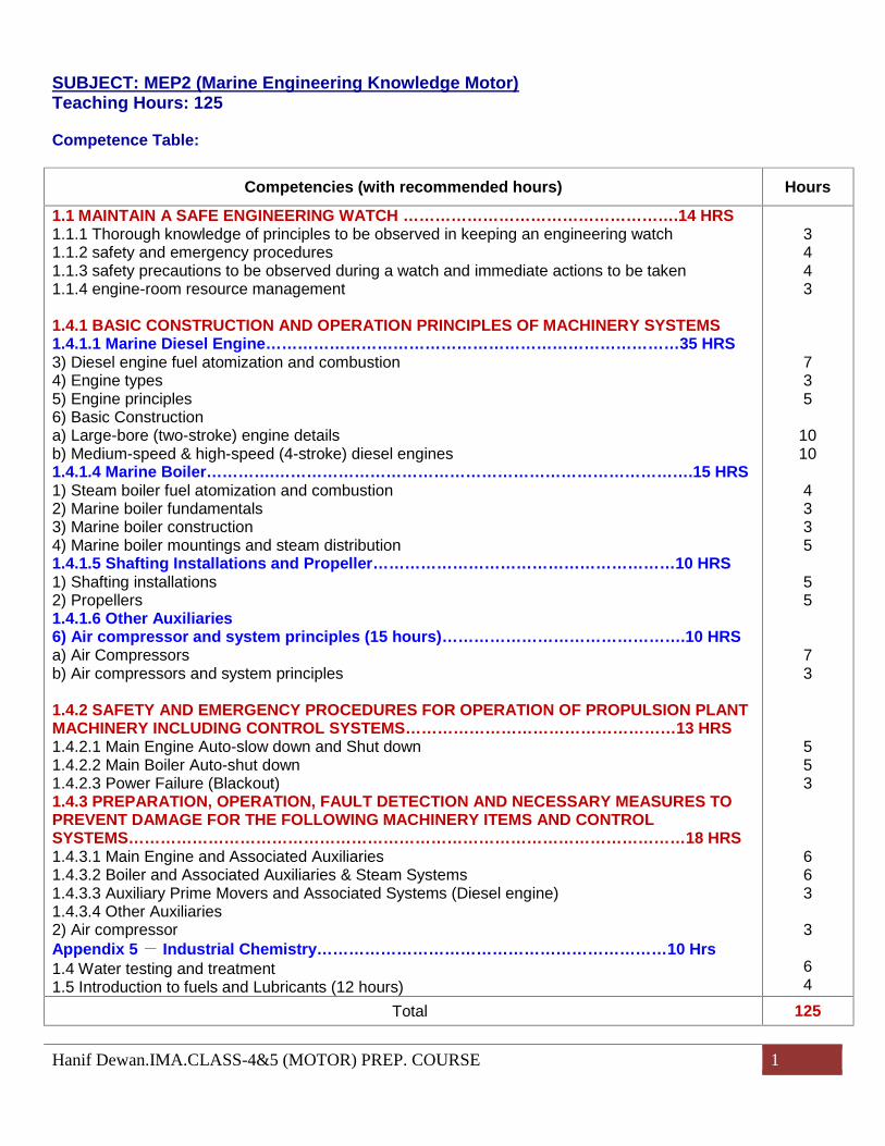
SUBJECT: MEP2 (Marine Engineering Knowledge Motor)Teaching Hours: 125
Competence Table:
Competencies (with recommended hours) Hours
1.1 MAINTAIN A SAFE ENGINEERING WATCH …………………………………………….14 HRS1.1.1 Thorough knowledge of principles to be observed in keeping an engineering watch1.1.2 safety and emergency procedures1.1.3 safety precautions to be observed during a watch and immediate actions to be taken1.1.4 engine-room resource management
1.4.1 BASIC CONSTRUCTION AND OPERATION PRINCIPLES OF MACHINERY SYSTEMS1.4.1.1 Marine Diesel Engine……………………………………………………………………35 HRS3) Diesel engine fuel atomization and combustion4) Engine types5) Engine principles6) Basic Constructiona) Large-bore (two-stroke) engine detailsb) Medium-speed & high-speed (4-stroke) diesel engines1.4.1.4 Marine Boiler………….…………………………………………………………………….15 HRS1) Steam boiler fuel atomization and combustion2) Marine boiler fundamentals3) Marine boiler construction4) Marine boiler mountings and steam distribution1.4.1.5 Shafting Installations and Propeller…………………………………………………10 HRS1) Shafting installations2) Propellers1.4.1.6 Other Auxiliaries6) Air compressor and system principles (15 hours)……………………………………….10 HRSa) Air Compressorsb) Air compressors and system principles
1.4.2 SAFETY AND EMERGENCY PROCEDURES FOR OPERATION OF PROPULSION PLANTMACHINERY INCLUDING CONTROL SYSTEMS……………………………………………13 HRS1.4.2.1 Main Engine Auto-slow down and Shut down1.4.2.2 Main Boiler Auto-shut down1.4.2.3 Power Failure (Blackout)1.4.3 PREPARATION, OPERATION, FAULT DETECTION AND NECESSARY MEASURES TOPREVENT DAMAGE FOR THE FOLLOWING MACHINERY ITEMS AND CONTROLSYSTEMS……………………………………………………………………………………………18 HRS1.4.3.1 Main Engine and Associated Auxiliaries1.4.3.2 Boiler and Associated Auxiliaries & Steam Systems1.4.3.3 Auxiliary Prime Movers and Associated Systems (Diesel engine)1.4.3.4 Other Auxiliaries2) Air compressorAppendix 5- Industrial Chemistry…………………………………………………………10 Hrs1.4 Water testing and treatment1.5 Introduction to fuels and Lubricants (12 hours)
3443
735
1010
4335
55
73
553
663
3
64
Total 125

Hanif Dewan.IMA.CLASS-4&5 (MOTOR) PREP. COURSE 2
COMPETENCE DETAILS:
Competencycode Learning Objectives Hours
1.1
1.1.1
1.1.2
1.1.3
1.1 Maintain a Safe Engineering Watch
1.1.1 THOROUGH KNOWLEDGE OF PRINCIPLES TO BE OBSERVED INKEEPING AN ENGINEERING WATCH– Explains principles to be observed in an engineering watch atsea and in port, including following based on the provisionsconcerned in the STCW Code Ch VIII, Section A-VIII/1, A-VIII/2and B-VIII/2– duties associated with taking over a watch and acceptinga watch– routine duties undertaken during a watch– maintenance of the machinery space logs and thesignificance of the reading taken– duties associated with handing over a watch– Explains standards/regulations for watchkeeping in a national law if any– States the importance, ordinance and arrangements of watchkeeping, and theneed to: wear appropriate clothes, safety shoes and a safety helmet; carry a torch lamp; maintain bodily functions; be awake and highly consciousness
1.1.2 SAFETY AND EMERGENCY PROCEDURES– States what is meant by emergency in accordance with components of themachinery– States that each component/installation constructing propulsion machinery canbe isolated from the entire system and can be run manually– Explains remedial/emergency procedures and conditions in accordance withcomponents of the machinery in such an event of power failure– States procedures for recovery and malfunctions considered to be likely occurredin steering gears in case of blackout and other causes including procedures forchangeover of remote-auto to electric hydraulic driven at machine side and handpump hydraulic driven at machine side respectively
1.1.3 SAFETY PRECAUTIONS TO BE OBSERVED DURING A WATCH ANDIMMEDIATE ACTIONS TO BE TAKEN– Explains the importance of engine-room rounds before taking over the watch andperiodic rounds during the watch– Explains the need to be at places where communication with bridge and chiefengineer is always available except engine-room rounds or carrying communicationmeans– Explains the need to have an incentive and positive mental attitude emphasizingthat officers in charge of the engineering watch assume a great responsibility in thesafe navigation
Hanif Dewan.IMA.CLASS-4&5 (MOTOR) PREP. COURSE 3
1.1.4
1.4.1
1.4.1.1
– Explains the need to pay continuous attention to all the running parameters ofmachinery and to what tasks are being carried out by other personnel concerned– Explains the need to be well-versed in structure of the engine-room includingevacuation route and installations/equipment for emergency– States that arrangements of fire-extinguishing installations should be clearlyunderstood including sorts and number of fire-extinguisher in accordance with typesof ship– States immediate actions to be taken in the event of accidents such as fire, aperson overboard, oil spill and flooded, emphasizing that the appropriate immediateactions minimize damage– Explains necessary measures to contain oil spreading in the event of oil spillincluding communicating information/report, preparation of the dedicated apparatusagainst oil spill, plugging of scupper pipes and stopping oil systems
1.1.4 ENGINE-ROOM RESOURCE MANAGEMENT (ERM)– Explains ERM principles based on Bridge Resource Management(BRM)/ERM principles described in STCW Code Ch Section A-VIII/2, Part 3paragraph 8– Explains ERM in terms of maintaining the safe engineering watch including whyERM is necessary– Explains the resources considered to be included in ERM– Explains the resource management in a specific manner taking examples such aspersonnel management, information management and management ofinstallations/equipment– Explains what is necessary to practice ERM– Explains what is meant by the following in practicing ERM– allocation, assignment and prioritization of the resources– effective communication– assertiveness and leadership– obtaining and maintaining situational awareness– consideration of team experience
1.4.1 BASIC CONSTRUCTION AND OPERATION PRINCIPLES OF MACHINERYSYSTEMS1.4.1.1 Marine Diesel Engine3) Diesel engine fuel atomization and combustion– Describes the combustion process in a boiler or an engine cylinder– Describes the chemical reaction in combustion as being between combustiblematerials such as hydrocarbon on fuels and the oxygen contained in atmosphericair– Sketches a section through a typical injector nozzle assembly– Explains how atomization is produced by the injector nozzle– Explains why swirl and penetration are important to the ignition and combustion ofthe fuel/air mixture– Describes the care necessary with injector nozzle holes
4) Engine types– States that marine diesel engines are normally described in broad categories bythe bore of their cylinders and their rotational speed– States that large-bore engines are normally fitted with piston rods and crossheads– States that smaller diesel engines normally have trunk pistons and gudgeon pin inthe place of piston rods and crossheads
Hanif Dewan.IMA.CLASS-4&5 (MOTOR) PREP. COURSE 4
– States that large-bore engines are normally directly connected to the propellerand therefore rotated at low speed– States that other diesel engines may run at medium speed or high speed,depending upon their duty– States that medium-speed and high-speed engines are often used as directdrives for generation of electrical power– States that medium-speed engines (and occasionally high-speed engines) areused, through some form of speed reduction, as main propulsion engines.– States the approximate speed ranges related to the following engines: low-speed medium-speed high-speed
5) Engine principles– Sketches typical indicator diagrams for: a two-stroke engine a four-stroke engine
– Explains the problems of obtaining indicator diagrams from slow-speed, medium-speed and high-speed engines– States that peak pressures are sometimes measured which give an indication ofengine power and performance– Develops the expression: , to produce an expression for thepower of a diesel engine in terms of m.e.p., number of cylinders, length of stroke,diameter of piston and r.p.m.– Calculates indicated power, using given dimensions, r.p.m., m.e.p. and theexpression developed in the above objective– States typical compressions and maximum pressures for slow-, medium-andhigh-speed engines– states, for a marine propulsion diesel engine, typical values of: brake thermal efficiency mechanical efficiency fuel consumption in kg per kW hour
6) Basic Constructiona) Large-bore (two-stroke) engine details– Describes with the aid of a simple single line sketch, naming the material ofmanufacture, the assembled construction of the principal components of a dieselengine, including: the bedplate a main bearing an 'A' frame and entablature guides a liner a cooling-water jacket a cylinder head a diaphragm a turbocharger the scavenge trunk an air cooler the crankshaft a connecting rod a crosshead
Hanif Dewan.IMA.CLASS-4&5 (MOTOR) PREP. COURSE 5
a piston a bottom end bearing a top end bearing the camshaft a push rod a rocker an exhaust valve or port an air-inlet port the chain or gear train driving the camshaft
– Sketches a section through a piston, showing the cooling arrangements–– Describes, with the aid of simple sketches, the following valves, showingprinciple parts, materials and method of operation: exhaust valve cylinder lubricator fuel valve cylinder relief valve air-starting valve crankcase relief valve jerk fuel pump
including the pressures at which the two relief valves operate– With the aid of engine manufacturers' manuals, defines specified work clearancesof all bearing and sliding surfaces and interference fits, where applicable– Describes, with the aid of diagrams, the distribution of lubricating oil to the guides,top-end, bottom-end and main bearings when pistons are oil-cooled and whenwater-cooled
b) Medium-speed and high-speed (four-stroke) diesel engines– Lists the services for which auxiliary diesel engines are used– Name the materials used in the manufacture of the listed items, then describe,with the aid of sketches, the assembled construction of these items: the bedplate a cylinder block a cylinder jacket a cylinder liner a cylinder head the exhaust gas manifold the air-inlet manifold the air cooler the engine crankcase a bearing housing and shell the lubrication-oil sump a piston a connecting rod a gudgeon pin the crankshaft the camshaft and chain the push rods the fuel injector the air inlet and exhaust valves and rockers
– Sketches typical timing diagrams for medium-speed and high-speed dieselengines– Describes, with the aid of diagrams, a lubrication and piston-cooling system for a
Hanif Dewan.IMA.CLASS-4&5 (MOTOR) PREP. COURSE 6
1.4.1.2
medium-speed diesel engine– Explains why it is important to maintain the lubricating oil and fuel filters clean andin good condition1.4.1.2 Marine Steam Turbine2) Basic construction– Names the materials used in the manufacture of the listed items, then describe,with the aid of sketches, the assembled construction of these items: high pressure turbine casing low pressure turbine casing astern turbine casing low pressure turbine exhaust casing high pressure turbine rotor low pressure turbine rotor receiver pipe reduction gear wheels pinions main condenser gland condenser gland packing steam leak-off reservoir gland packing steam reservoir gland packing steam leak-off reservoir gland packings gland steam make-up valve, gland steam spill valve manoeuvring valve astern guardian valve flexible coupling thrust bearing labyrinth packings nozzles blades (moving blade, stationary blade) shroud
– States the feature of impulse turbine– States the feature of reaction turbine– Sketches types of turbine plant arrangement– bleeder turbine (extraction turbine)– regenerative turbine– reheat turbine
3) Operation principles– Explains why main condenser is kept in vacuum– Explains how to keep main condenser in vacuum– Describes the importance of draining inside turbine casing– Explains the function of manoeuvring valve– Explains the role of extraction steam– Describes how to keep the hotwell level of condenser– Explains spinning operation– Explains the meaning of throttle governing and nozzle governing, which is theway of control of turbine output– Explains meaning of auto-spinning system– States that the main turbines are provided with a satisfactory emergency supplyof lubricating oil, which will come into use automatically in case of failure oflubricating oil system
Hanif Dewan.IMA.CLASS-4&5 (MOTOR) PREP. COURSE 7
1.4.1.3
1.4.1.4
1.4.1.3 Marine Gas Turbine1) Operation principles– Explains how a gas turbine is used for– Describes the feature of a gas turbine– Describes the operation principles in terms of four processes, compression,combustion (heating), expansion and exhaust– Compares a gas turbine with a steam turbine in terms of advantages anddisadvantages– Describes the types of gas turbines
2) Basic construction– Using visual aids, describes the three main components of gas turbine as:– compressor– combustion chamber– turbine– Describes the types of compressors and their features– Describes the types of combustion chambers and their features– Describes the types of turbine and their features– Lists the attached equipment and explains their feature and functions in simpleterms
1.4.1.4 Marine Boiler1) Steam boiler fuel atomization and combustion– States that, to ensure that the combustion process is as compete as possible,excess air is normally supplied– States that the excess of air must be kept to a minimum, consistent with goodcombustion– States that poor combustion creates smoke, which pollutes the atmosphere andwastes fuel and reduces the efficiency of the engine or boiler– Explains why the proportion of CO2 or O2 in exhaust gases provides anindication of combustion efficiency– States the ranges of percentages of CO2 which indicate: good combustion poor combustion bad combustion
– Explains the importance of atomization when it is required to mix a liquid fuel withair prior to combustion– States the theoretical air/fuel ratio for a typical boiler fuel– States the actual air/fuel ratio allowing for normal excess air, in:– the furnace of a steam boiler– the cylinder of a diesel engine– Sketches a section through the nozzle assembly of a pressure-jet burner– States that in the above objective atomization is produced by the fuel, at highpressure, passing through a small orifice in the burner nozzle– Describes the attention required by burner atomizer tips– Describes, with a single line diagram, a combustion air register identifying: swirl vanes the quarl the flame stabilizer air-flow control valves the burner
Hanif Dewan.IMA.CLASS-4&5 (MOTOR) PREP. COURSE 8
– Describes furnace conditions which indicate good combustion– Describes, with the aid of sketches, how pressure-jet, steam-jet and rotary-cupburners atomize fuel and promote adequate fuel/air mix ratio
2) Marine boiler fundamentals– Describes, with the aid of diagrams, an auxiliary boiler steam system togetherwith identifying the services supplied by steam– States typical pressures of steam produced in auxiliary boilers and averagesystem supply pressures– States that auxiliary steam boilers range from simple fire-tube boilers to self-contained fully automated package units– Explains simply and briefly, with the aid of diagrams, the principal differencesbetween a fire-tube boiler, a water-tube boiler and a packaged boiler
3) Marine boiler construction– Describes the material commonly used for construction in a fire-tube boiler– Describes, with the aid of sketches, the general constructional details of a fire-tube boiler, showing how the parts are connected to form a compete structure– States that, for pressure vessels: shells of cylindrical form give a higher strength/weight ratio than other
shapes the cylindrical shell can be sited vertically or horizontally dished or spherical end-plates give a higher strength than flat end-plates of similar thickness all flat surfaces must be properly stayed to resist deformation stays can have the form of solid bars, thick tubes or plate girders corrugated furnaces provide higher strength and flexibility than plain
furnaces of similar thickness
– States why boiler is usually installed on board diesel engine ships– Explains and outlines a boiler system listing associated systems including theircomponents– Explains the relationship between a boiler and exhaust gas economizer– Explains ignition system including the function of burner control– Describes the principles of construction, operation and control of a packagedboiler
4) Marine boiler mountings and steam distribution– Identifies the following boiler fittings and position on boiler shell (supply shelldiagram for fitting to be married/drawn and identified):– main steam outlet (or "stop") valve– auxiliary steam stop valve– safety valves and easing gear– water level gauges– feed inlet valve– blow-down valve– scumming valve– soot blowers– connections for pressure gauges– air release valve– sampling valve– Explains the importance of boiler mounted valves

Hanif Dewan.IMA.CLASS-4&5 (MOTOR) PREP. COURSE 9
1..4.1
1.4.1.5
– Identifies the following internal boiler fitting and internal position within boiler shell:– feedwater distribution unit– scumming pan– blow-down dip pipe– Explains the purpose of the valves and fittings listed in the above objectives,comparingthe differences, where applicable, between water-tube and fire-tube boilers– Explains the purpose of a reducing valve– Describes the operation of a reducing valve, using a single line sketch– Explains how steam pipes are supported– Explains how expansion and contraction are allowed for in steam pipes– Describes the different methods of joining lengths of a steam pipe– Explains the purpose of drains and steam traps– Describes the operation of steam traps– Describes the procedure for warming through a steam line and explains thecause, in simple terms, of water hammer and how water hammer can be avoided– Explains the outline of steam supply system including its components/installations– Describes the means used to minimize the possibility of oil contaminating theboiler feed water
1.4.1 BASIC CONSTRUCTION AND OPERATION PRINCIPLES OF MACHINERYSYSTEMS
1.4.1.5 Shafting Installations and Propeller1) Shafting installations– Describes the following installations/equipment constructing shafting:– propeller– rope guard– stern tube– stern tube bearing– shaft seal– propeller shaft– intermediate shaft– aft bearing– plumber block– thrust bearing– Describes the details of oil shaft seal and stern tube bearing including theircomponents– Describes the details of thrust bearing2) Propellers– Describes various types of propellers and their features– Describes structure and materials for propellers– Defines the following parameters of propeller:– diameter– pitch– pitch ratio– boss ratio– pressure side– suction side– leading edge– following edge– blade section

Hanif Dewan.IMA.CLASS-4&5 (MOTOR) PREP. COURSE 10
1.4.1.6
1.4.2
1.4.2.1
– blade rake– Explains briefly how propellers fit on propeller shafts– Describes a highly -skewed (skew back) propeller and its advantages– Describes a controllable pitch propeller (CCP) and its mechanism of changingblade angle– States the advantages and disadvantages of a controllable pitch propeller incomparison with fixed pitch propeller (FPP)– Defines the cavitation of propellers and explains its generating mechanism– Defines the propeller singing and explains its generating mechanism andpreventive measures
1.4.1.6 Other Auxiliaries6) Air compressor and system principlesa) Air Compressors– Describes an air compressor as a pump which takes air from the atmosphereand, with an input of energy, compresses it in one or more states to a smallervolume with higher pressure and temperature– Explains the reason for cooling the air, during and after the compression– States that the compressed air is stored in steel reservoirs until required for somepurpose, such as staring a diesel engine– States that, during the compression process, the relationship: constant willapply– States that air can be treated as an ideal gas and that the relationship :Constant will also apply– States that for the air storage tank the relationship: will apply, where:m = mass of air stored in the tank (kg)R = specific gas constant for air (=8314 J/kg/K)T =temperature of air, in kelvin unitsP = air pressure, in Newtons per square metreV = volume of reservoir tank, in cubic metres– Solves simple numerical problems related to the above objectives
b) Air compressors and system principles– Lists shipboard uses of compressed air– States the common pressure limit of single-stage compressors– States that, in order of restrict the rise of air temperature during compression, theair is cooled by circulating water around the cylinder– States that air compressor can be single-stage or multi-stage reciprocating orrotary machines– Describes the compression processes in a two-stage reciprocating compressor– Draws a line diagram of a two-stage air compressor. indicating stage airpressures and temperatures– Explains why intercoolers and after-coolers are used
1.4.2 SAFETY AND EMERGENCY PROCEDURES FOR OPERATION OFPROPULSION PLANT MACHINERY INCLUDING CONTROL SYSTEMS1.4.2.1 Main Engine Auto-slow down and Shut down– Explains main engine auto-slow down and shut down taking a typical system asan example in terms of the following:– specific conditions– processes appeared until slow-slow down/shut down– transient phenomenon of the plant
Hanif Dewan.IMA.CLASS-4&5 (MOTOR) PREP. COURSE 11
1.4.2.2
1.4.2.3
1.4.3
1.4.3.1
– procedures for recovery (changeover of manoeuvring position, manoeuvringmethod, eliminating causes and etc.)– main engine control system– Explains main engine manual emergency slow down and shut down in terms ofthe following, taking a typical system as an example– specific conditions– impacts on the plant– procedures for recovery
1.4.2.2 Main Boiler Auto-shut down– Explains main boiler auto-shut down taking a typical system as an example interms of the following:– specific conditions– processes appeared until shut down– impacts on the plant under way and in port– procedures for recovery (eliminating causes, reigniting burner and etc.)– main boiler control system (changeover of control system, position and etc.)
1.4.2.3 Power Failure (Blackout)– Explains briefly power supply system on board ships and its backup system– Explains specific conditions of blackout and procedures for recovery respondingto their causes taking a typical system as an example, including the following:– transient phenomenon of the plant– equipment/installations to be promptly addressed– sequential restarting auxiliaries– auxiliaries to be manually restarted– generator control system and power distributing system
1.4.3 PREPARATION, OPERATION, FAULT DETECTION AND NECESSARYMEASURES TO PREVENT DAMAGE FOR THE FOLLOWING MACHINERYITEMS AND CONTROL SYSTEMS1.4.3.1 Main Engine and Associated AuxiliariesThe following can be applied to diesel engine, steam turbine and gas turbine exceptfor some of them:– Explains the outline of main machinery system listing associated systemsincluding their components– States precautions, safety measures, checking procedures and points to be madeas preparations before starting up main engine– States the need for warming up/cooling down main engine or keeping it at hotcondition unless cooling down has been done– States precautions for starting associated auxiliaries to establish each systemconstructing propulsion machinery such as fuel oil, lubricating oil, cooling systemand starting air system– States particularly, precautions against auxiliaries which repair/overhaul wascarried out– States precautions to start main engine turning– States the importance of carrying out all procedures in an orderly manner in orderto prevent malfunction and damage– Explains the critical speed/revolution caused by torsional vibration of shaftingsystem– Explains how running parameters such as temperatures, pressures and levelscan be determined in normal range

Hanif Dewan.IMA.CLASS-4&5 (MOTOR) PREP. COURSE 12
1.4.3.2
1.4.3.3
– Explains what malfunctions are likely occur due to running parameters getting outof the normal range– Describes how to carry out the cleaning of turbocharger under way– Explains how to keep running of main diesel engine under the condition of cuttingfuel oil to one cylinder or more– Explains how to keep running of main diesel engine under the condition ofreducing the number of turbochargers– Describes the conditions which create dangerous oil mists in crankcases– Explains the importance of keeping scavenge air spaces and supercharge air-spaces drained and clean– Describes the correct procedure and actions to take if a fire occurs in thescavenge air space or in the supercharge air space when an engine is running– Describes the action to be taken if a turbocharger surges
1.4.3.2 Boiler and Associated Auxiliaries, and Steam Systems (16 hours)– States procedures for igniting the burner manually and automatically– States how to build up the steam pressure and to put boiler into service– Explains precautions and necessary measures to be taken when getting upsteam–– States the function of safety valve and how to adjust the setting point to blow– Explains operation methods of boiler and economizer under way– Explains precautions for using exhaust gas economizer– Describes the method used to ensure that all pipes, cocks, valves and otherfittings used for indicating water level are clear and in good working order– Explains the treatment of boiler water including examination of properties of boilerwater, including surface and bottom blow of boiler water– States what is meant by soot blow including the function of soot blowers– Explains what malfunctions /troubles likely happen to boiler on its operation– States precautions for opening high temperature steam valves– Explains how to keep boiler in cold condition while it is out of service– Describes the correct procedures for operating steaming boilers in parallel onload– Describes the correct procedures for checking the water level in steaming boilers– Describes the danger of oil entering a boiler with the feedwater– Explains what is meant by "blow-back" and explains how blow-back can beavoided–– Explains why the temperature of boiler exhaust gases should be maintainedabove a minimum value1.4.3.3 Auxiliary Prime Movers and Associated Systems– States precautions before starting an engine such as confirming fuel oil line,starting air line, cooling sea/fresh water line established and amount of lubricatingoil inside the sump tank– Describes briefly components constructing each associated system for an engine– States preparations and procedures for manual start of an engine– States the conditions of remote-auto start of an engine– States the differences between manual start and remote-auto start of an engine– Describes briefly the control system and its components including their function– States the safety devices and their functions– Lists the normal operating pressures and/or temperatures for:– exhaust gas– inlet air– circulating water at inlet and outlet
Hanif Dewan.IMA.CLASS-4&5 (MOTOR) PREP. COURSE 13
1.4.3.4
APPENDIX5
1.4
1.5
– lubricating oil– fuel1.4.3.4 Other Auxiliaries2) Air compressor– States that cylinder lubrication must be kept to a minimum consistent with correctand safe operation– States that cylinder lubricating oil should not have a flashpoint below 210℃ andthe use of synthetic lubricating oil to reduce a hazard– Describes the attention required to keep the intake air filter working effectively– Explains the reason for fitting drain valves after air coolers– Describes the starting-up and stopping procedures– Explains the principles upon which air compressors are run automatically– Describes the particular quality required for compressed air that is to be used incontrol systems– Explains how the required quality in the above objective is achieved
Appendix 5- Industrial Chemistry (45 Hrs)
1.4 Water testing and treatment (12 hours)- recognizes the importance of controlling the pH value of aqueous solutionswithin the minimum corrosive range- identifies the chemical additives that can be used to obtain the condition requiredin the above objective- knows the importance of maintaining a gas free condition in the water used to"feed" a steam boiler or to circulate in an engine cooling system- identifies the methods in common use for conditioning the water content ofmarine Power plant, e.g. trisodium phosphate, hydrazine- explains that natural water supplies contain metallic salts in solution- demonstrates the standard method of measuring metallic salt content, i.e. statethe Actual quantity of metallic salt present in a specified quality of water- knows the standard measurement given in the above objective as in units of"parts per million" (ppm) or less accurately in '32's' (seawater densitymeasurement)- lists the main metallic salts found in: fresh water average seawater defines: permanent hardness temporary hardness
- defines briefly how scale and sludge are produced in a steam boiler- explains the different effects of using seawater, fresh water and distilled water asboiler feedwater- defines the principal objects of treatment of boiler feedwater
1.5 Introduction to fuels and Lubricants (12 hours)- identifies the average carbon, hydrogen, sulphur and ash content of the followingfuels: petrol kerosene marine diesel fuel boiler fuel oil

Hanif Dewan.IMA.CLASS-4&5 (MOTOR) PREP. COURSE 14
- defines flashpoint and explains its importance for marine fuels and lubricants- knows flashpoint temperature for the following hydrocarbons: petrol kerosene marine diesel fuel boiler fuel oil lubricating oil
- identifies the minimum closed flashpoint of marline fuels- states the maximum temperature to which fuel oil may be raised- describes precautions taken on board ship to prevent accidental ignition of theoils listed in the above objective- defines viscosity in terms of resistance to flow- demonstrates why it is necessary to raise the temperature of some fuel oils- carries out tests on fuels and lubricants for: flashpoint viscosity
- explains the reason why values of flashpoint or of viscosity need to be known forthe following:- fuels and lubricants in storage- transfer of fuels and lubricants- carries out tests on fuels and lubricants for water content
Hanif Dewan.IMA.CLASS-4&5 (MOTOR) PREP. COURSE 1
SUBJECT: NASC (Naval Architecture & Ship Construction)Teaching Hours: 50
Competence Table:
Competencies (with recommended hours) HOURS
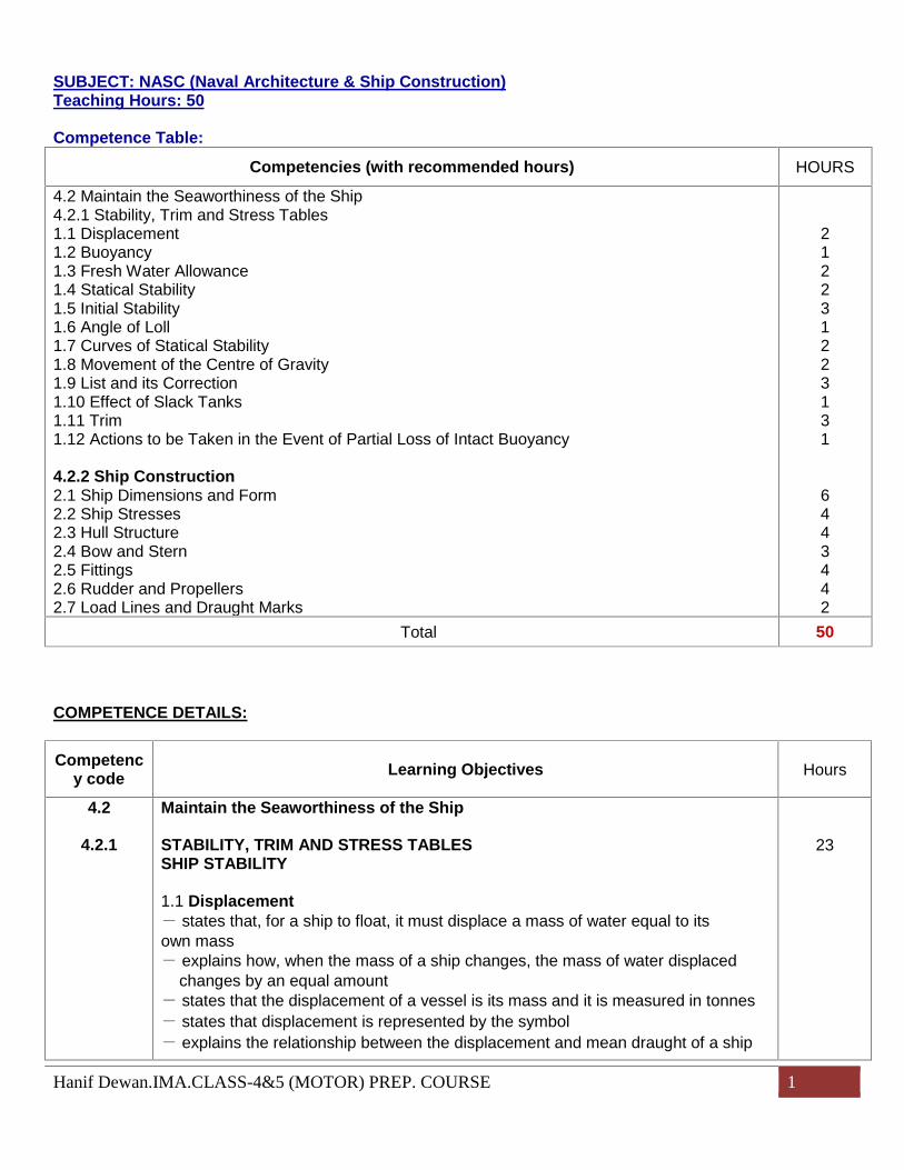
4.2 Maintain the Seaworthiness of the Ship4.2.1 Stability, Trim and Stress Tables1.1 Displacement1.2 Buoyancy1.3 Fresh Water Allowance1.4 Statical Stability1.5 Initial Stability1.6 Angle of Loll1.7 Curves of Statical Stability1.8 Movement of the Centre of Gravity1.9 List and its Correction1.10 Effect of Slack Tanks1.11 Trim1.12 Actions to be Taken in the Event of Partial Loss of Intact Buoyancy
4.2.2 Ship Construction2.1 Ship Dimensions and Form2.2 Ship Stresses2.3 Hull Structure2.4 Bow and Stern2.5 Fittings2.6 Rudder and Propellers2.7 Load Lines and Draught Marks
212231223131
6443442
Total 50
COMPETENCE DETAILS:
Competency code Learning Objectives Hours
4.2
4.2.1
Maintain the Seaworthiness of the Ship
STABILITY, TRIM AND STRESS TABLESSHIP STABILlTY
1.1 Displacement- states that, for a ship to float, it must displace a mass of water equal to itsown mass- explains how, when the mass of a ship changes, the mass of water displaced
changes by an equal amount- states that the displacement of a vessel is its mass and it is measured in tonnes- states that displacement is represented by the symbol- explains the relationship between the displacement and mean draught of a ship
23

Hanif Dewan.IMA.CLASS-4&5 (MOTOR) PREP. COURSE 2
by using the graph or scale- given a displacement/draught curve, finds:- displacements for given mean draughts- mean draughts for given displacements- the change in mean draught when given masses are loaded or discharged- the mass of cargo to be loaded or discharged to produce a required change
of draught- defines' light displacement' and 'load displacement'- defines 'deadweight'- uses a deadweight scale to find the deadweight and displacement of a ship at
various draughts in seawater- defines 'tonnes per centimetre immersion'(TPC)- explains why TPC varies with different draughts- uses a deadweight scale to obtain TPC at given draughts- uses TPC obtained from a deadweight to find:- the change of mean draught when given masses are loaded or discharged- the mass of cargo to be loaded or discharged to produce a required change
of draught- defines 'block coefficient'(Cb)- calculates Cb from given displacement and dimensions- calculates displacement from given Cb and dimensions
1.2 Buoyancy- explains what is meant by 'buoyancy'- states that the force of buoyancy is an upward force on a floatingobject created by the pressure of liquid on the object- states that the buoyancy force is equal to the displacement of a floating object- describes reserve buoyancy- explains the importance of reserve buoyancy- explains how freeboard is related to reserve buoyancy- explains the purpose of load lines R1- explains the requirements for maintaining watertight integrity Section A-V/2- demonstrates an understanding of damage stability requirements for certainvessels- explains reasons for damage stability requirements- identifies damage stability requirements for Type A vessels, Type (B 60)andType (B-100) vessels- identifies equilibrium condition after flooding for Type A, and all Type B vessels- identifies damage stability requirements for passenger vessels
1.3 Fresh Water Allowance- explains why the draught of a ship decreases when it passes from fresh waterto seawater and vice versa- states that when loading in fresh water before proceeding into seawater, a shipis allowed a deeper maximum draught- describes what it meant by the fresh water allowance (FWA)- given the FWA and TPC for fresh water, calculates the amount which can beloaded after reaching the summer load line when loading in fresh water before
Hanif Dewan.IMA.CLASS-4&5 (MOTOR) PREP. COURSE 3
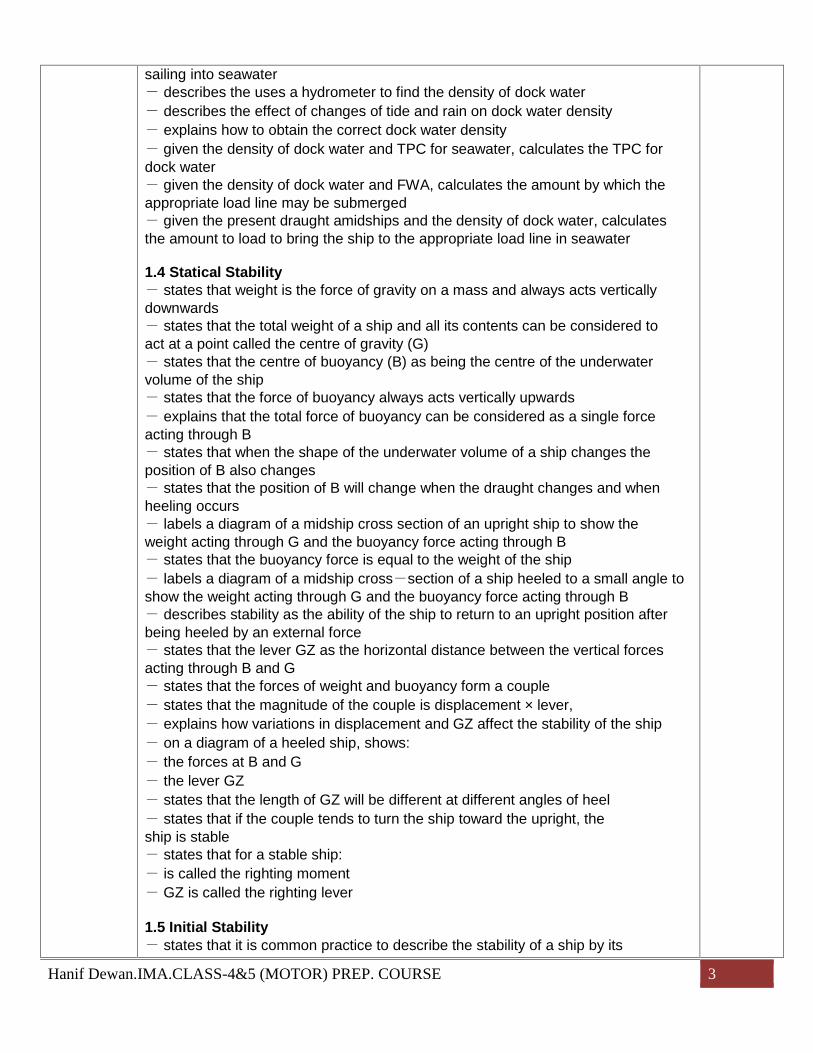
sailing into seawater- describes the uses a hydrometer to find the density of dock water- describes the effect of changes of tide and rain on dock water density- explains how to obtain the correct dock water density- given the density of dock water and TPC for seawater, calculates the TPC fordock water- given the density of dock water and FWA, calculates the amount by which theappropriate load line may be submerged- given the present draught amidships and the density of dock water, calculatesthe amount to load to bring the ship to the appropriate load line in seawater
1.4 Statical Stability- states that weight is the force of gravity on a mass and always acts verticallydownwards- states that the total weight of a ship and all its contents can be considered toact at a point called the centre of gravity (G)- states that the centre of buoyancy (B) as being the centre of the underwatervolume of the ship- states that the force of buoyancy always acts vertically upwards- explains that the total force of buoyancy can be considered as a single forceacting through B- states that when the shape of the underwater volume of a ship changes theposition of B also changes- states that the position of B will change when the draught changes and whenheeling occurs- labels a diagram of a midship cross section of an upright ship to show theweight acting through G and the buoyancy force acting through B- states that the buoyancy force is equal to the weight of the ship- labels a diagram of a midship cross-section of a ship heeled to a small angle toshow the weight acting through G and the buoyancy force acting through B- describes stability as the ability of the ship to return to an upright position afterbeing heeled by an external force- states that the lever GZ as the horizontal distance between the vertical forcesacting through B and G- states that the forces of weight and buoyancy form a couple- states that the magnitude of the couple is displacement × lever,- explains how variations in displacement and GZ affect the stability of the ship- on a diagram of a heeled ship, shows:- the forces at B and G- the lever GZ- states that the length of GZ will be different at different angles of heel- states that if the couple tends to turn the ship toward the upright, theship is stable- states that for a stable ship:- is called the righting moment- GZ is called the righting lever
1.5 Initial Stability- states that it is common practice to describe the stability of a ship by its
Hanif Dewan.IMA.CLASS-4&5 (MOTOR) PREP. COURSE 4
reaction to heeling to small angles (up to approximately 10°)- defines the transverse metacentre (M) as the point of intersection ofsuccessive buoyancy force vectors as the angle of heel increases by a small angle- states that, for small angles of heel, M can be considered as a fixed point onthe centreline- on a diagram of a ship heeled to a small angle, indicates G, B, Z and M- shows on a given diagram of a stable ship that M must be above G and statesthat the metacentric height GM is taken as positive- shows that for small angles of heel (θ),- states that the value of GM is a useful guide to the stability of a ship- describes the effect on a ship's behaviour of:-a large GM (stiff ship)-a small GM (tender ship)- uses hydrostatic curves to find the height of the metacentre above the keel(KM) at given draughts- states that KM is only dependent on the draught of a given ship- given the values of KG, uses the values of KM obtained from hydrostaticcurves to find the metacentre heights, GM- states that, for a cargo ship, the recommended initial GM should not normallybe less than 0.15m
1.6 Angle of Loll- shows that if G is raised above M, the couple formed by the weight andbuoyancy force will turn the ship further from the upright- states that in this condition, GM is said to be negative and is called theupsetting moment or capsizing moment- explains how B may move sufficiently to reduce the capsizing moment to zeroat some angle of heel- states that the angle at which the ship becomes stable is known as the angleof loll- states that the ship will roll about the angle of loll instead of the upright- states that an unstable ship may loll to either side- explains why the condition described in the above objective is potentiallyDangerous
1.7 Curves of Statical Stability- states that for any one draught the lengths of GZ at various angles of heel canbe drawn as a graph- states that the graph described in the above objective is called a curve ofstatical stability- states that different curves are obtained for different draughts with the sameinitial GM- identifies cross curves (KN curves and MS curves)- derives the formula- derives the formula- derives GZ curves for stable and initially unstable ships from KN curves- from a given curve of statical stability obtains:- the maximum righting lever and the angle at which it occurs- the angle of vanishing stability

Hanif Dewan.IMA.CLASS-4&5 (MOTOR) PREP. COURSE 5
- the range of stability- shows how lowering the position of G increases all values of the righting leverand vice versa- states that angles of heel beyond approximately 40°are not normally ofpractical interest because of the probability of water entering the ship at largerangles
1.8 Movement of the Centre of Gravity- states that the centre of gravity (G) of a ship can move only when masses aremoved within, added to, or removed from the ship- states that:- G moves directly towards the centre of gravity of added masses- G moves directly away from the centre of gravity of removed masses- G moves parallel to the path of movement of masses already on board- calculates the movement of G (GG1) from:- performs calculations as in the above objective to find the vertical andhorizontal shifts of the centre of gravity resulting from adding, removing ormoving masses- states that if a load is lifted by using a ship's derrick or crane, the weight isimmediately transferred to the point of suspension- states that if the point of suspension is moved horizontally, the centre of gravityof the ship also moves horizontally- states that if the point of suspension is raised or lowered, the centre of gravityof the ship is raised or lowered- calculates, by using moments about the keel, the position of G after loading ordischarging given masses at stated positions- calculates the change in KG during a passage resulting from:- consumption of fuel and stores- absorption of water by a deck cargo- accretion of ice on decks and superstructures given the masses and theirPositions
1.9 List and its Correction- shows on a diagram the forces which cause a ship to list when G is to one sideof the centreline- states that the listing moment is given by displacement × transverse distanceof G from the centreline- shows on a diagram that the angle of list (θ) is given bywhere is the transverse shift of G from the centreline- states that in a listed condition the range of stability is reduced- given the displacement, KM and KG of a ship, calculates the angle of listresulting from loading or discharging a given mass at a stated position, or frommoving a mass through a given transverse distance- explains, with reference to moments about the centreline, how the list may beremoved- given the displacement, GM and the angle of list of a ship, calculates the massto load or discharge at a given position to bring the ship upright- given the displacement, GM and angle of list of a ship, calculates the mass tomove through a given transverse distance to bring the ship upright

Hanif Dewan.IMA.CLASS-4&5 (MOTOR) PREP. COURSE 6
- given the draught, beam and rise of the floor, calculates the increase indraught resulting from a stated angle of list
1.10 Effect of Slack Tanks- states that if a tank is full of liquid, its effect on the position of the ship's centreof gravity is the same as if the liquid were a solid of the same mass- explains by means of diagrams how the centre of gravity of the liquid in a partlyfilled tank moves during rolling- states that when the surface of a liquid is free to move, there is a virtualincrease in KG, resulting in a corresponding decrease in GM- states that the increase in KG is affected mainly by the breadth of the freesurface and is not dependent upon the mass of liquid in the tank- states that in tankers the tanks are often constructed with a longitudinalsubdivisionto reduce the breadth of free surface
1.11 Trim- states that "trim" is the difference between the draught aftand the draught forward- states that trim may be changed by moving masses already on board forwardor aft, or by adding or removing masses at a position forward of or abaft thecentre of flotation- states that 'centre of flotation' is the point about which the ship trims,and states that it is sometimes called the tipping centre- states that the centre of flotation is situated at the centre of area of thewaterplane, which may be forward of or abaft amidships- demonstrates the uses hydrostatic data to find the position of the centre offlotation for various draughts- states that a trimming moment as mass added or removed × its distanceforward or aft of the centre of flotation; or, for masses already on board, as massmoved × the distance moved forward or aft- states that the moment to change trim by 1 cm (MCT 1cm) as the momentabout the centre of flotation necessary to change the trim of a ship by 1 cm- demonstrates the uses hydrostatic curves or deadweight scale to find the MCT1cm for various draughts- given the value of MCT 1cm, masses moved and the distances moved forwardor aft, calculates the change in trim- given the value of MCT 1 cm, the position of the centre of flotation, massesadded or removed and their distances forward of or abaft the centre of flotation,calculates the change of trim- given initial draughts and the position of the centre of f1otation, extends thecalculation in the above objective to find the new draughts- given initial draughts and TPC, extends the calculation in the above objectiveto find the new draughts R1- given initial draughts and TPC, extends the calculation to find the new draughts- demonstrates the uses of a trimming table or trimming curves to determinechanges in draughts resulting from loading, discharging or moving weights- states that in cases where the change of mean draught is large, calculation ofchange of trim by taking moments about the centre of flotation or by means oftrimming tables should not be used

Hanif Dewan.IMA.CLASS-4&5 (MOTOR) PREP. COURSE 7
4.2.2
- calculates final draughts and trim for a planned loading by considering changesto a similar previous loading
1.12 Actions to be Taken in the Event of Partial Loss of Intact Buoyancy- states that flooding should be countered by prompt closing of watertight doors,valves and any other openings which could lead to flooding of othercompartments- states that cross flooding arrangements, where they exist, should be put intooperation immediately to limit the resulting list- states that any action which could stop or reduce the inflow of water should betaken4.2.2 THE PRINCIPAL STRUCTURAL MEMBERS OF A SHIPTextbooks: T58Teaching aids: A1
Required performance:SHIP CONSTRUCTION2.1 Ship Dimensions and Form- illustrates the general arrangement of the following ship types:- general cargo- tankers- bulk carriers- combination carriers- container- RO-RO- passenger- reproduces an elevation of a general cargo ship, showing holds, engine room,peaktanks, double bottom tanks, hatchway, tween deck and position of bulkheads- reproduces an elevation of a typical crude oil carrier, showing bulkheads,cofferdams, pump room, engine room, bunker and peak tanks, cargo tanks, sloptankand permanent ballast tanks- reproduces a plan view of a tanker, showing the arrangement of cargo and ballasttanks- defines and illustrates:- camber- rise of floor- tumblehome- flare- sheer- rake- parallel middle body- entrance- run- defines:- forward perpendicular(FP)- after perpendicular (AP)- length between perpendiculars(LBP)
27

Hanif Dewan.IMA.CLASS-4&5 (MOTOR) PREP. COURSE 8
- length on the waterline (LWL)- length overall (LOA)- base line- moulded depth, beam and draught- extreme depth, beam and draught2.2 Ship Stresses- describes in qualitative terms shear force and bending moments- explains what is meant by 'hogging' and by 'sagging' and distinguishesbetween them- describes the loading conditions which give rise to hogging and saggingstresses- describes how hogging and sagging stresses are caused by the sea state- explains how hogging and sagging stresses result in tensile or compressiveforces in the deck and bottom structure- describes water pressure loads on the ship's hull- describes liquid pressure loading on the tank structures- calculates the pressure at any depth below the liquid surface, given the densityof the liquid- describes qualitatively the stresses set up by liquid sloshing in a partly filled tank- describes racking stress and its causes- explains what is meant by 'panting' and states which part of the ship is affected- explains what is meant by 'pounding 'or 'slamming' and states which part of theship is affected- describes stresses caused by localized loading- demonstrates understanding of modern methods of determining the effects ofdifferent loading and ballasting on the ship's structure- demonstrates ability to use one of the modern mechanical or electrical aids fordetermining stress- understands the input and output data from stress calculation machines andhas a working knowledge of the stress tables- states the purpose of a shipboard stress finding system, including details ofinput data and the output obtained- describes how output data from ship stress finding system may be used- appreciates torsion stress particularly with reference to container ship loading- analyses the stress areas created by bending moments and shearing forcesderived by a stress indicator- analyses the causes and effects of shearing forces and bending moments onships' structures- defines bending moment as the difference between moment of buoyancy andmoment of weight- defines shearing forces in terms of the difference between buoyancy and weight- extracts information from shear force and bending moment diagrams- describes the constructional features which compensate for stress- describes corrosion- describes the causes of corrosion on board- describes the various methods that being used to minimize the effect of corrosion2.3 Hull Structure- identifies structural components on ships' plans and drawings:
Hanif Dewan.IMA.CLASS-4&5 (MOTOR) PREP. COURSE 9
- frames, floors, transverse frames, deck beams, knees, brackets- shell plating, decks, tank top, stringers- bulkheads and stiffeners, pillars- hatch girders and beams, coamings, bulwarks- bow and stern framing, cant beams, breasthooks- describes the types of materials that are used in the construction of a ship- describes and illustrates standard steel sections:- flat plate- offset bulb plate- equal angle- unequal angle- channel- tee- describes with aids of sketches the longitudinal, transverse and combinedsystems of framing on transverse sections of the ships- sketches the arrangement of frames, webs and transverse members for eachsystem- illustrates double bottom structure for longitudinal and transverse framing- illustrates hold drainage systems and related structure- illustrates a duct keel- sketches the deck edge, showing attachment of sheer strake and stringer plate- sketches a radiused sheer strake and attached structure- describes the stress concentration in the deck round hatch openings- explains compensation for loss of strength at hatch openings- sketches a transverse section through a hatch coaming, showing thearrangementof coamings and deep webs- sketches a hatch corner in plain view, showing the structural arrangements- sketches deck freeing arrangements, scuppers, freeing ports, open rails- illustrates the connection of superstructures to the hull at the ship's side- sketches a plane bulkhead, showing connections to deck, sides and doublebottom and the arrangement of stiffeners- sketches a corrugated bulkhead- explains why transverse bulkheads have vertical corrugations and for and aftbulkheads have horizontal ones R1- describes the purpose of bilge keels and how they are attached to the ship's side2.4 Bow and Stern- describes the provisions of additional structural strength to withstand pounding- describes and illustrates the structural arrangements forward to withstand panting- describes the function of the sternframe- describes and sketches a sternframe for a single-screw ship- describes and illustrates the construction of a transom stern, showing theconnections to the sternframe R12.5 Fittings- describes and sketches an arrangement of modern weather deck mechanicalsteel hatches- describes how watertightness is achieved at the coamings and cross joints- describes the cleating arrangements for the hatch covers
Hanif Dewan.IMA.CLASS-4&5 (MOTOR) PREP. COURSE 10
- describes the arrangement of portable beams, wooden hatch covers andtarpaulins- sketches an oiltight hatchcover-- describes roller, multi angle, pedestal and Panama fairleads- sketches mooring bitts, showing their attachment to the deck-, sketches typical forecastle mooring and anchoring arrangements showing theleads of moorings- describes the construction and attachment to the deck of tension winches andexplains how they are used- describes the anchor handling arrangements from hawse pipe to spurling pipe- describes the construction of chain lockers and how the bitter-ends are securedin the lockers- explains how to secure anchors and make spurling pipes watertight in preparationfor a sea passage- describes the construction and use of a cable stopper- describes the construction of masts and Sampson posts and how they aresupported at the base- describes the construction of derricks and deck cranes- describes the bilge piping system of a cargo ship-- states that each section is fitted with a screw down nonreturn suction valve- describes and sketches a bilge strum box- describes a ballast system in a cargo ship- describes the arrangement of a fire main and states what pumps may be usedto pressurize it- describes the provision of sounding pipes and sketches a sounding pipearrangement- describes the fitting of air pipes to ballast tanks or fuel oil tanks- describes the arrangement of fittings and lashings for the carriage of containerson deck2.6 Rudder and Propellers- describes the action of the rudder in steering a ship- reproduces drawings of modern rudders: semi balanced, balanced and spade- explains the purpose of the rudder carrier and pintles- explains how the weight of the rudder is supported by the rudder carrier- describes the rudder trunk- describes the arrangement of a watertight gland round the rudder stock- explains the principle of screw propulsion- describes a propeller and defines, with respect to :- boss- rake- skew- face- back- tip- radius- pitch- compares fixed pitch with controllable pitch propellers- sketches the arrangement of an oil lubricated sterntube and tailshaft

Hanif Dewan.IMA.CLASS-4&5 (MOTOR) PREP. COURSE 11
- describes how the propeller is attached to the tailshaft- sketches a cross section of a shaft tunnel for water cooled and oil cooled type- explains why the shaft tunnel must be of watertight construction and how wateris prevented from entering the engine-room if the tunnel becomes flooded2.7 Load Lines and Draught Marks- explains where the deck line is marked- defines 'freeboard'- explains what is meant by 'assigned summer freeboard'- draws to scale the load line mark and the load lines for a ship of a givensummer moulded draught, displacement and tonnes per centimetre immersionin salt water- explains how the chart of zones, areas and seasonal periods is used to find theapplicable load line- demonstrates how to read draughts- explains that the freeboard, measured from the upper edge of the deck line tothe water on each side, is used to check that the ship is within its permitted limits ofloading

Hanif Dewan.IMA.CLASS-4&5 (MOTOR) PREP. COURSE 1
Subject: Machine DrawingTeaching Hours: 50
Course Outline:
Competence Table:
Competencies (with recommended hours) HOURS
3.2.6 INTERPRETATION OF MACHINERY DRAWINGS AND HANDBOOKS MARINEENGINEERING DRAWING AND DESIGN (63 hours).1 Types of Drawing (2 hours).2 Linework (4 hours).3 Pictorial Projection (4 hours).4 Development (4 hours).5 Dimensioning (5 hours).6 Geometrical Tolerancing (2 hours).7 Limits and Fits (2 hours).8 Engineering Drawing Practice & Assembly Drawing
1) AIR INLET VALVE2) AUTOMATIC VALVE3) REDUCING VALVE4) RUDDER CARRIER BEARING5) STARTING AIR VALVE
3.2.7 THE INTERPRETATION OF PIPING, HYDRAULIC AND PNEUMATIC DIAGRAMS (5 hrs)
2444522
22
5Total 50
COMPETENCE DETAILS:
Competencycode Learning Objectives Hours
3.2.6
3.2.6.1
3.2.6.2
3.2.6 INTERPRETATION OF MACHINERY DRAWINGS AND HANDBOOKSMARINE ENGINEERING DRAWING AND DESIGN (63 hrs)Textbooks: T 46Teaching aids: A 1
Required performance:3.2.6.1 Types of Drawing (2 hours)– Explains the purpose of a general arrangement– Explains the purpose of assembly drawings– Explains the purpose of component drawings– Explains the use of collective single-part drawings– Explains the use of pictorial drawings– Lists the standard/routine information and references commonly given ondrawings3.2.6.2 Linework (4 hours)– Relates examples of lines to applications and vice-versa
45
Hanif Dewan.IMA.CLASS-4&5 (MOTOR) PREP. COURSE 2
3.2.6.3
3.2.6.4
3.2.6.5
3.2.6.6
3.2.6.7
– Draws tangents as required in practice– Demonstrates what is meant by: first-angle projection third-angle projection
and sketches the correct symbol for both cases– Using given examples, completes first-and third-angle projections with: missing lines missing views simple plotted curves
– Re-draws given simple components and provides sufficient dimensions for theirmanufacture– Completes orthographic projections of solids– Completes sectional views in orthographic projection– Draws a third-angle projection with hidden detail– Explains the use of auxiliary projection3.2.6.3 Pictorial Projection (4 hours)– Draws isometric projections of simple solids– Draws oblique projections of simple solids3.2.6.4 Development (4 hours)– Draws the development of a 90°intersection of circular trucking– Draws the development of a cone– Draws the development of a square pyramid– Draws the development of a square-to-round transition piece3.2.6.5 Dimensioning (5 hours)– Dimensions a simple component, applying all correct standards– Explains the advantage of datum dimensioning3.2.6.6 Geometrical Tolerancing (2 hours)– Explains briefly what is meant by geometrical tolerancing– Relates symbols for geometrical tolerancing to the intended characteristics– Using given reference material, applies tolerancing data to engineering drawings,to include examples of: straightness flatness roundness cylindricity concentricity squareness parallelism angularity position
3.2.6.7 Limits and Fits (2 hours)– Explains the need for limits and fits– Given various ways of indicating limits of size, explains their meaning– Explains the meaning of: tolerance actual size basic size nominal size Explains hole basis fits Explains shaft basis fit Explains, using examples: clearance fits transition fits interference fits
Hanif Dewan.IMA.CLASS-4&5 (MOTOR) PREP. COURSE 3
3.2.6.8
3.2.7
– Describes, using examples, the cumulative effect of tolerances– Explains what is meant by selective assembly– Lists the factors which influence the selection of tolerances3.2.6.8 Engineering Drawing Practice (22 hours)– Makes engineering drawings employing the following: sections in two parallel planes revolved sections thin sections part sections half sections hidden detail machinery symbols surface finish angular dimensions arrow heads auxiliary dimensions centre lines pitch-circle diameters threads thick chain-lines enlarged views hatching leader lines Using reference material, applies abbreviations to drawings Applies conventional representation of the following features external and internal threads squares on shafts serrated and splinted shafts holes on a linear and on a circular pitch bearings interrupted views tension and compression springs Assembly Drawing
1) AIR INLET VALVE2) AUTOMATIC VALVE3) REDUCING VALVE4) RUDDER CARRIER BEARING5) STARTING AIR VALVE6) FUEL VALVE7) GEAR PUMP8) HYDRAULIC STEERING GEAR9) CONTROL VALVE10) CYLINDER RELIEF VALVE
3.2.7 THE INTERPRETATION OF PIPING, HYDRAULIC AND PNEUMATICDIAGRAMS (5 hours)Textbooks: T24, T46, T50Teaching aids: A1
Required performance:– States that piping diagrams indicate all the information necessary for ship'smachineryfittings– Explains that piping diagrams include design characteristics of the system and
5
Hanif Dewan.IMA.CLASS-4&5 (MOTOR) PREP. COURSE 4
propulsion plant– Explains how to interpret piping diagrams taking a major system as an example– Explains major symbol marks used in piping diagrams– Explains major symbol marks used in hydraulic and pneumatic diagrams– Explains operation mechanism of the major devices used in the hydraulic andpneumaticsystems and how they work

Hanif Dewan.IMA.CLASS-4&5 (MOTOR) PREP. COURSE 1
Subject: MEO CLASS- 4&5 (MOTOR) ORAL EXAMTeaching Hours: 50
Course Outline:
Competence Table:
Competencies (with recommended hours) HOURS
1. ENGINE ROOM WATCH KEEPING2. RUNNING & MAINTENANCE OF VARIOUS MACHINERIES:3. AIR COMPRESSORS AND SYSTEM PRINCIPLES4. GENERATOR ALTERNATORS:5. FIRE & SAFETY6. REFRIGERATION7. MARINE DIESEL ENGINE SAFE & EFFICIENT OPERATION & MAINTENANCE MARINE
DIESEL8. MARINE DIESEL ENGINE9. CHIEF ENGINEER’S ADMINISTRATIONAL DUTIES & FORMALITIES10. KNOWLEDGE REGARDING DRY DOCKING & SAFTY SURVEY11. BANGLADESH SHIPPING ACTS12. MARINE LAWS
2553537
53336
Total 50
COMPETENCE DETAILS:
Competencycode Learning Objectives Hours
1.11.1.1
1.1.2
1.1.4
1.4.1
1.51.5.1
1. ENGINE ROOM WATCH KEEPING
1.1 Maintain a safe engineering watch1.1.1 Thorough knowledge of principles to be observed in keeping an engineeringwatch1.1.2 Safety and emergency procedures1.1.3 Safety precautions to be observed during a watch and immediate actions tobe taken1.1.4. Engine-room resource management
2. RUNNING & MAINTENANCE OF VARIOUS MACHINERIES:
PUMPS & PIPING:1.4.1 Basic construction & operation principles (Manual/Automatic) of various
Pumps1.5 Operate Fuel, Lubrication, Ballast and other Pumping system1.5.1 Operational Characteristics of Pumps & Piping systems including Control
Hanif Dewan.IMA.CLASS-4&5 (MOTOR) PREP. COURSE 2
1.4.1
1.5.21.5.3
1.4.1
2.2.2
4.3
1.4
STEERING GEARS:1.4.1 Diagrammatic arrangement of Manually operated Steering system
(fluid flow and Characteristics of major systems) with Steering gearcompartment & Navigation Bridge
OILY WATER SEPARATOR1.5.2 Bilge Pumping System1.5.3 Oily Water Separator, Requirements & Operation
3. AIR COMPRESSORS AND SYSTEM PRINCIPLES
1.4.1 Basic construction and operation principles of machinery systems Operation of air compressors
4. GENERATOR ALTERNATORS: Construction Operation Maintenance Operational safties Changing & paralleling generators
2.1.1.3 Generators A.C. Generators D.C Generators
2.2.2 MAINTENANCE AND REPAIR2.2.2.2 Generator (5 hours) States the safety and isolation precautions necessary before commencing
work Lists the parts to be inspected, their common faults and the necessary
remedial action Tests and records values of insulation resistance Performs routine maintenance and testing of a generator
5. FIRE & SAFETY(Operation & maintenance of fire fighting equipments, fire identification &fire prevention)4.3.1 Fire Prevention4.3.2 Organizing Fire Drills4.3.3 Chemistry of Fire4.3.4 Fire- Fighting System4.3.5 The Action to be taken in the event of Fire, Including fires involvingOIL
6. REFRIGERATION
1.4.1.6 2) (a) Marine Refrigeration Cycle(b) Principle of Refrigeration
3) Air conditioning and Ventilation systems
7. MARINE DIESEL ENGINE1.4 Operate main and auxiliry machinery and associated control systems1.4.1 Basic construction and operation principles of machinery systems
Fuel oil system

Hanif Dewan.IMA.CLASS-4&5 (MOTOR) PREP. COURSE 3
3.2.1
4.1.1
4.2.1
Lubricating system Cooling system
8. SAFE & EFFICIENT OPERATION & MAINTENANCE MARINE DIESELENGINE
Engine Operation & Safety1.4.1 Safety & emergency Procedure for operation of propulsion plant Machinery
including control system1.4.2 Preparation, Operation, Fault detection & necessary measures to prevent
Damage
1.4.3.1. MAIN ENGINE & ASSOCIATED AUXILIARIES : Crank case explosion, regulation, Explosion door, Oil mist detector Scavenge Fire, fitted CO2 extinguisher Starting Air line explosion, Flame trap Turbocharger surging
9. CHIEF ENGINEER’S ADMINISTRATIONAL DUTIES & FORMALITIES General & emergency situation in Engine room Maintaining sea worthy ness of ship Duties & responsibilites as per marine law & ILO convention
10. KNOWLEDGE REGARDING DRY DOCKING & SAFTY SURVEY
11. BANGLADESH SHIPPING ACTS
12. MARINE LAWS
3.2.1 SAFETY MEASURES TO BE TAKEN FOR REPAIR AND MAINTENANCEINCLUDING THE SAFE ISOLATION OF SHIPBOARD MACHINERY ANDEQUIPMENT REQUIRED BEFORE PERSONNEL ARE PERMITTED TO WORKON SUCH MACHINERY OR EQUIPMENT.1 ISM Code.2 SMS.3 Safety Measures to be Taken
4.1.1 THE PRECAUTIONS TO BE TAKEN TO PREVENT POLLUTION OF THEMARINE ENVIRONMENT1.1 International Convention for the Prevention of Pollution from Ships,1973 andthe Protocol of 1978 relating thereto (MARPOL 73/78)1.2 Convention of the Prevention of Marine Pollution by Dumping of Wastes andOther Matter (London Dumping Convention) (LDC)
4.1.2 ANTI POLLUTION PROCEDURES AND ASSOCIATED EQUIPMENT.1 Regulation 26 - Annex 1 MARPOL 73/78.2 Anti-Pollution Equipment
Hanif Dewan.IMA.CLASS-4&5 (MOTOR) PREP. COURSE 4
4.1.3
4.6.1
4.1.3 IMPORTANCE OF PROACTIVE MEASURES- describes the importance of proactive measures to protect the marineenvironment in terms of compliance with the concerning international and nationallaws or regulations- lists actual proactive measures to be taken on board ships when: Bunkering Transferring oil and other pollution substances Disposing of waste
4.6.1 IMO CONVENTIONS CONCERNING SAFETY OF LIFE AT SEA ANDPROTECTION OF THE MARINE ENVIRONMENT1.1 Introduction to Maritime Law (1 hour)- Lists the main originators of international conventions concerned withmaritime law are: International Maritime Organization (IMO) International Labour Organization (lLO) Comite Maritime International (CMI)
- Describes briefly: flag State jurisdiction coastal State jurisdiction port State jurisdiction
- Describes main elements of relevant IMO Conventions, e.g. SOLAS,MARPOL and STCW Load Line, SOLAS, STCW ILO The International Safety Management (ISM) Code
1.3 Safety (24 hours) International Convention on Load Lines, 1966 (LL 1966), as amended R3,
R11 (3 hours) SOLAS- International Convention for the Safety of Life at Sea, 1974 as
amended The International Safety Management (ISM) Code International Convention on Standards of Training, Certification and
Watchkeeping for Seafarers, 2010 (STCW)