mermag-m/mgf mgf-os mgf-is mast-mgf mast-sc pwi-sc credit : rish, kyoto univ
TRANSCRIPT

MERMAG-M/MGFMERMAG-M/MGF
MGF-OS
MGF-IS
MAST-MGF
MAST-SC
PWI-SC
Credit : RISH, Kyoto Univ.

MGF Block DiagramMGF Block Diagram
1 Hz SynchronizationEFD

CharacteristicsCharacteristics
Digital resolution pT 4 20 bit digitization
Measurement range nT ±2048
Data Rate & Volume
Resolution & Range
Sample Rate Hz 128 MGF-O
64 MGF-I
Data rate to DPU kbps 7.7 MGF-O
3.8 MGF-I
128
7.7
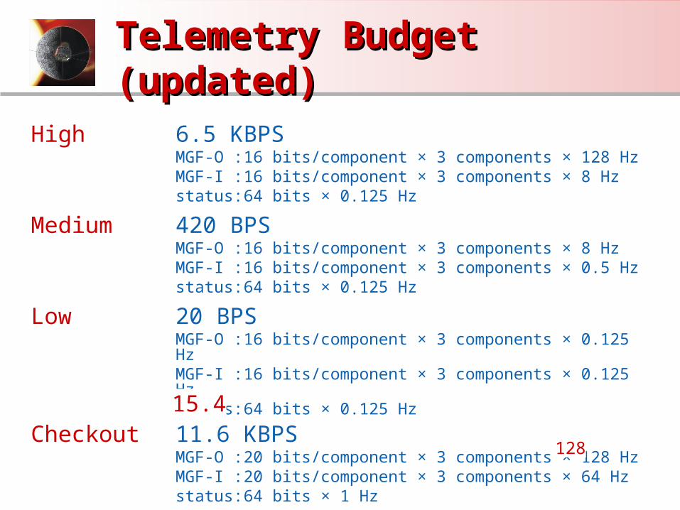
Telemetry Budget Telemetry Budget (updated)(updated)
High 6.5 KBPSMGF-O : 16 bits/component × 3 components × 128 HzMGF-I : 16 bits/component × 3 components × 8 Hzstatus: 64 bits × 0.125 Hz
Medium 420 BPSMGF-O : 16 bits/component × 3 components × 8 HzMGF-I : 16 bits/component × 3 components × 0.5 Hzstatus: 64 bits × 0.125 Hz
Low 20 BPSMGF-O : 16 bits/component × 3 components × 0.125 HzMGF-I : 16 bits/component × 3 components × 0.125 Hzstatus: 64 bits × 0.125 Hz
Checkout 11.6 KBPSMGF-O : 20 bits/component × 3 components × 128 HzMGF-I : 20 bits/component × 3 components × 64 Hzstatus: 64 bits × 1 Hz
128
15.4

MGF-I Recent Development &MGF-I Recent Development &Development plan in Apr. - Development plan in Apr. - Sep.Sep. Recent Development
Basic performance of BBM is confirmed to
be good.
20-bit ΔΣ A/D converter in BBM
Linearity error was found to be « 0.01%
and achieve the target.
Noise RMS was about 3 digits.
Development plan
For the test of amplifier having better
performance and feasibility test of the 128
Hz sampling, 2nd BBM is now
manufactured.
The sensor design will be fixed based on
the measurement of noise level and offset
in the wide temperature range from -160 to
200℃. INPUT
OU
TP
UT

1/128 secondsSynch. signal
1/64 seconds
1/256 seconds
Filtering coefficients and Filtering coefficients and frequency properties frequency properties of MGF-Iof MGF-I
frequency Hz
frequency Hz
frequency Hz
100 1000101
1 10 100 1000
1 10 100 1000
Phase delay
Time delay
Amplitude
Filter coefficients

MGF-O Heritage: VEXMAGMGF-O Heritage: VEXMAG
Heritage instruments – Venus Express VEXMAG
Launched on November 9, 2005.
On November 18 and 19, 2005 the commissioning of the
magnetometer (VEXMAG) as well as the boom deployment took place
successfully. Since then VEXMAG is operational with out any problems.
Venus Orbit Injection (VOI) is going to take place on April 11, 2006
followed by the near Venus commissioning of VEXMAG on April 22.

MGF-O Heritage: VEXMAG MGF-O Heritage: VEXMAG (cont.)(cont.)
Proof of instrument performance during boom deployment
Eigen frequency oscillation of the boom measured with a 100 pT peak-
to-peak field signal at 8 Hz (bottom right plot)
17:06:41.518.11.05
17:06:41.7518.11.05
17:06:4218.11.05
550
551
552
553
554
555
OS
-Z [n
T]
17:06:4318.11.05
17:06:4418.11.05
17:06:4518.11.05
114
114.5
115
OS
-Z [n
T]
17:06:4118.11.05
17:06:41.518.11.05
17:06:4218.11.05
17:06:42.518.11.05
17:06:4318.11.05
17:06:43.518.11.05
17:06:4418.11.05
17:06:44.518.11.05
17:06:4518.11.05
100
200
300
400
500
600
OS
-Z [n
T]

MGF-O Heritage: ThemisMGF-O Heritage: Themis
Heritage instruments – Themis FGM
Themis (launch: October 2006) flight models (five instruments) were
delivered and integrated to common DPU as well as boom.
Spacecraft 1 is presently being transported to JPL for environmental
tests.

Development Plan Mar.-June Development Plan Mar.-June 0606
MGF-O: IGEP (Germany)1. A set of ringcores, manufactured by exclusively high temperature
materials, has been produced and is currently under test.2. Upgrade of Magnestrode for calibration and test measurements up to
200 °C is ongoing.3. More detailed thermal modeling of the fluxgate sensor is ongoing.
IWF(Austria)1. The design study of a sigma-delta DAC for the possible use in the
digital magnetometer concept has been finished. It cannot be used due to a too high non-linearity: search for other options.
2. The effect of the periodic synchronization of the MGF-O data acquisition by the MGF-I 1Hz clock has been studied using a Matlab/Simulink simulation: effect is acceptable but nevertheless the simulations will be continued in order to further reduce it.

Status of Sensor Harness Status of Sensor Harness TestingTesting
Already performed tests: 1) Basic thermal analysis 2) Standard outgassing (@125 °C) 3) High temperature outgassing (@240 °C) Conclusion of 1-3: The Goretex (ePTFE) insulation and protection
wrap of the cable is mechanically stable up to 250 °C with no mass loss below this temperature. The thermo-optical properties are 0.05 (alphaS) and 0.79 (epsilonIR).
However the "harder" tests are coming in the near future. ESTEC is still waiting for other samples which will also take part in the UV/VUV test at elevated temperature. The test will probably start this week and will last for several weeks.

MERMAG-P / MAG DesignMERMAG-P / MAG Design
PowerSupply
Instrument Controller
Inboard Sensor
Electronics
OutboardSensor
Electronics
HeaterPower
InstrumentPower
SpaceWireInterface
SensorThermistors
OutboardSensor
InboardSensor
SensorHarness
SensorHarness
MA
G In
stru
men
t Ele
ctro
nics
Box
Prime hardware responsibilities: IGEP: Sensor and sensor electronics IWF: Instrument controller IC: Power supply and E-box
Sensor and near sensor electronics are going to be nearly identical to MGF-O design