mesh generation - cae usershomepages.cae.wisc.edu/~tautges/slides-10.04.day1.pdf · 22 12 12 10 8...
TRANSCRIPT

Mesh Generation
Timothy J. Tautges
Principle Member Technical StaffSandia National Laboratories
Adjunct Professor, Engineering PhysicsUniversity of Wisconsin-Madison
Sandia is a multiprogram laboratory operated by Sandia Corporation, a Lockheed Martin Company,for the United States Department of Energy under contract DE-AC04-94AL85000.

What is mesh generation?
• Geometry from CAD (SDRC Ideas, Pro/Engineer, etc.)• Mesh type determined by analysis; tetrahedra, hexah edra
most common
Continuous domain(Geometry)
Discretized Domain(Mesh)
Discrete Solution(FEA Results)
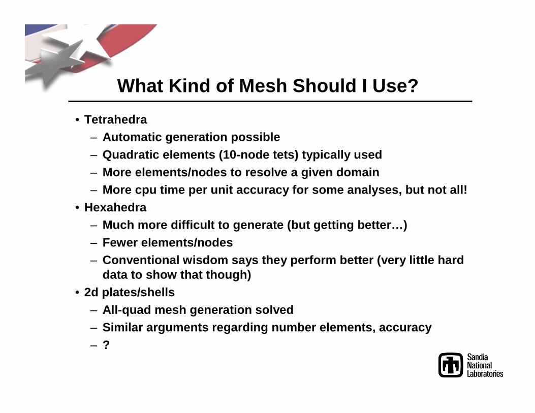
What Kind of Mesh Should I Use?
• Tetrahedra– Automatic generation possible– Quadratic elements (10-node tets) typically used– More elements/nodes to resolve a given domain– More cpu time per unit accuracy for some analyses, but not all!
• Hexahedra– Much more difficult to generate (but getting better…)– Fewer elements/nodes– Conventional wisdom says they perform better (very little hard
data to show that though)• 2d plates/shells
– All-quad mesh generation solved– Similar arguments regarding number elements, accura cy– ?

Overall We Use A Geometry-Focused Process
symmplane
position
“foam”
“steel case” “impact”
Material Bound Cond Init Cond
⊗⊗⊗⊗
• Why:– Less interactive detail– Fine geom ≈≈≈≈ Coarse
geom– Basis: initial CAD
model
• Model generation:1.Start with well-defined
design model2.Use simplification
strategies to obtain analysis model
3.Generate mesh…
Geometry: Mesh1:
Mesh2:
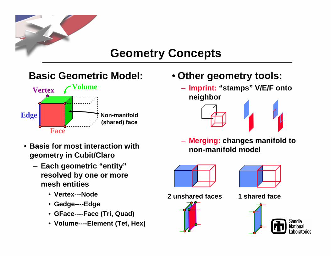
Geometry Concepts
• Basis for most interaction with geometry in Cubit/Claro– Each geometric “entity”
resolved by one or more mesh entities
• Vertex---Node• Gedge----Edge• GFace----Face (Tri, Quad)• Volume----Element (Tet, Hex)
• Other geometry tools:– Imprint: “stamps” V/E/F onto
neighbor
– Merging: changes manifold to non-manifold model
Vertex
Edge
Face
Volume
Non-manifold(shared) face
Basic Geometric Model:
2 unshared faces 1 shared face

Tetrahedral Mesh Generation
• Automatic (Delaunay) meshing algorithm (almost) always used for volumes
• Surface meshing using Delaunay (flat/parametric surfaces) or advancing front (curved/non-parametric surfaces)
Initial domain Point Placement Delaunay Triangulation
• Boundary recovery• Sliver removal (3D)
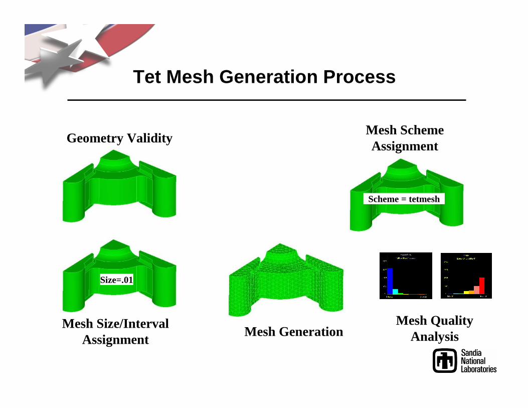
Tet Mesh Generation Process
Mesh Size/IntervalAssignment
Mesh GenerationMesh Quality
Analysis
Geometry Validity
Size=.01
Mesh SchemeAssignment
Scheme = tetmesh

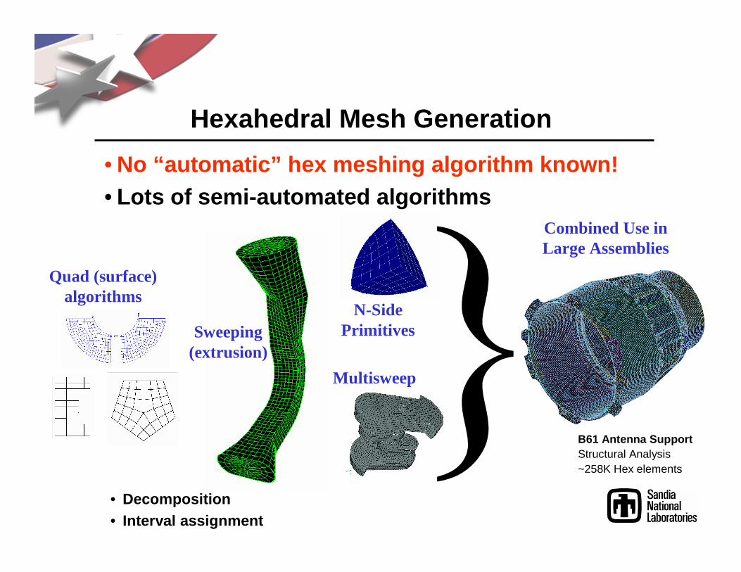
Hexahedral Mesh Generation
• No “automatic” hex meshing algorithm known!• Lots of semi-automated algorithms
Quad (surface)algorithms
Sweeping(extrusion)
N-SidePrimitives
Multisweep
Hexahedral Mesh Generation
• No “automatic” hex meshing algorithm known!• Lots of semi-automated algorithms
Quad (surface)algorithms
Sweeping(extrusion)
N-SidePrimitives
Combined Use inLarge Assemblies
Multisweep
B61 Antenna SupportStructural Analysis~258K Hex elements
• Decomposition• Interval assignment
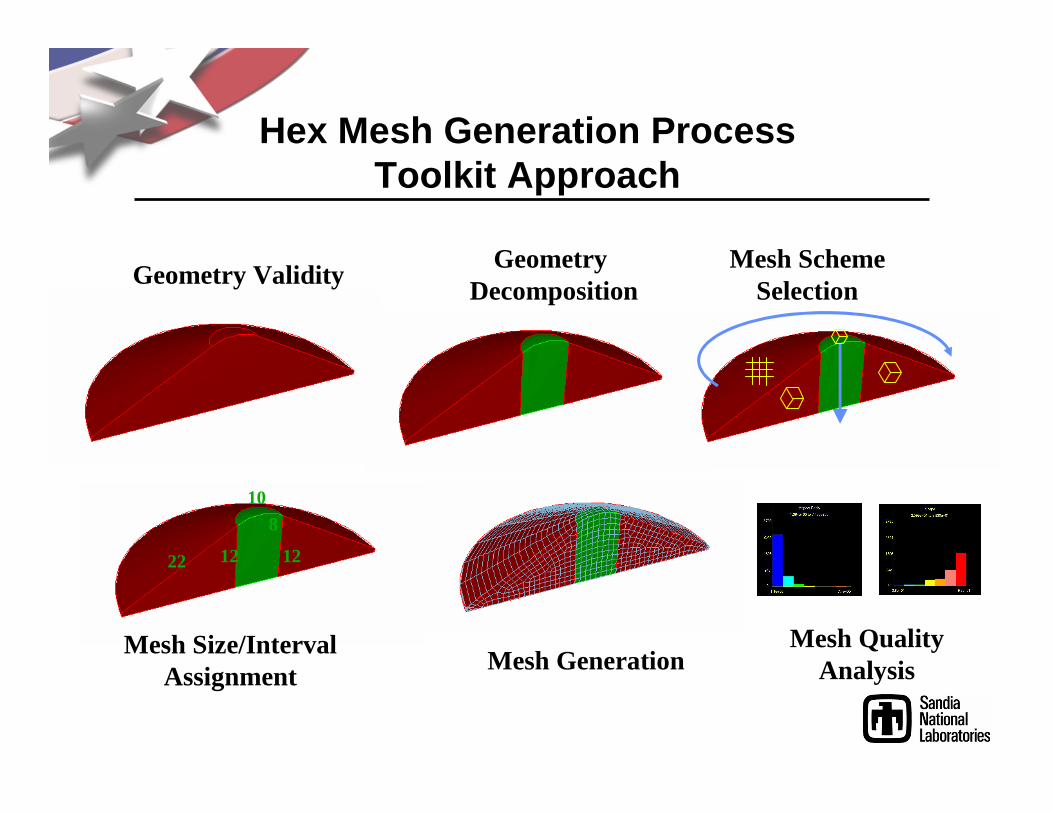
Hex Mesh Generation Process Toolkit Approach
Geometry Decomposition
Mesh SchemeSelection
12 1222
108
Mesh Size/IntervalAssignment
Mesh GenerationMesh Quality
Analysis
Geometry Validity

Boundary Conditions
• Three primary types of boundary condition groupings :– Element Block: not really a BC; groups elements for
purposes of material type identification– Nodeset: for assigning loads on nodes in the model,
e.g. Temperature, Force– Sideset: for assigning loads on faces in the model,
e.g. Pressure• Import into Ansys as named components , then use to
assign loads to model there
• Examples :Ø Block 100 volume 1
Ø Nodeset 2001 surface 1 2 3 curve 100 volume 3
Ø Export genesis ‘test.g’

Transferring Mesh to Ansys• Write mesh to “Exodus” or “Genesis” file ‘basename.g’• Translate to Ansys format: ‘exoans basename.g bname’
• Read into Ansys:– Enter pre-processing mode & select default material– “File->Read Input” from file ‘bname’ (includes other files by reference)
• Select->Comp/Assembly->Select Comp/Assembly– Proceed as before, with BC’s, IC’s
Area BC
Nodal BC
Material type
Elements
Nodes
Concept
bname.elemElementsElements
bname.esetComponent EBxxxElem Block xxx
bname.ssetComponent SSxxxSideset xxx
bname.nsetComponent NSxxxNodeset xxx
bname.nodeNodesNodes
FileAnsysExodus
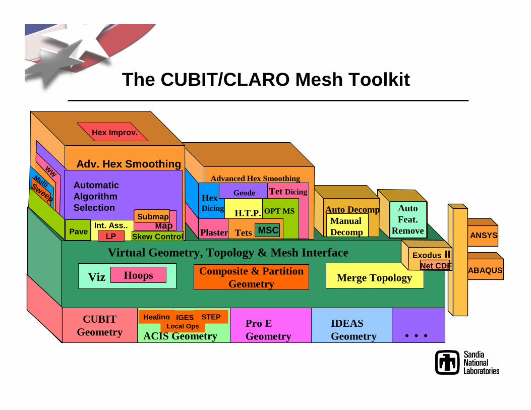
The CUBIT/CLARO Mesh Toolkit
Virtual Geometry, Topology & Mesh Interface
Viz Hoops Composite & PartitionGeometry
Merge Topology
CUBITGeometry ACIS Geometry
Pro EGeometry
IDEASGeometry . . .
ANSYS
ABAQUSNet CDFExodus II
STEPHealingLocal Ops
IGES
AutoFeat.
Remove
Auto DecompManualDecomp
Advanced Hex Smoothing
Tet DicingGeodeHexDicing H.T.P. OPT MS
Plaster Tets MSC
WW
Sweep
Adv. Hex Smoothing
Int. Ass..
Automatic Algorithm Selection
LPMap
Submap
Multi
PaveSkew Control
Hex Improv.
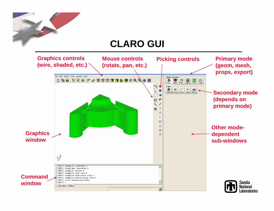
CLARO GUI
Command window
Graphics window
Primary mode (geom, mesh, props, export)
Secondary mode (depends on primary mode)
Other mode-dependent sub-windows
Graphics controls(wire, shaded, etc.)
Mouse controls(rotate, pan, etc.)
Picking controls
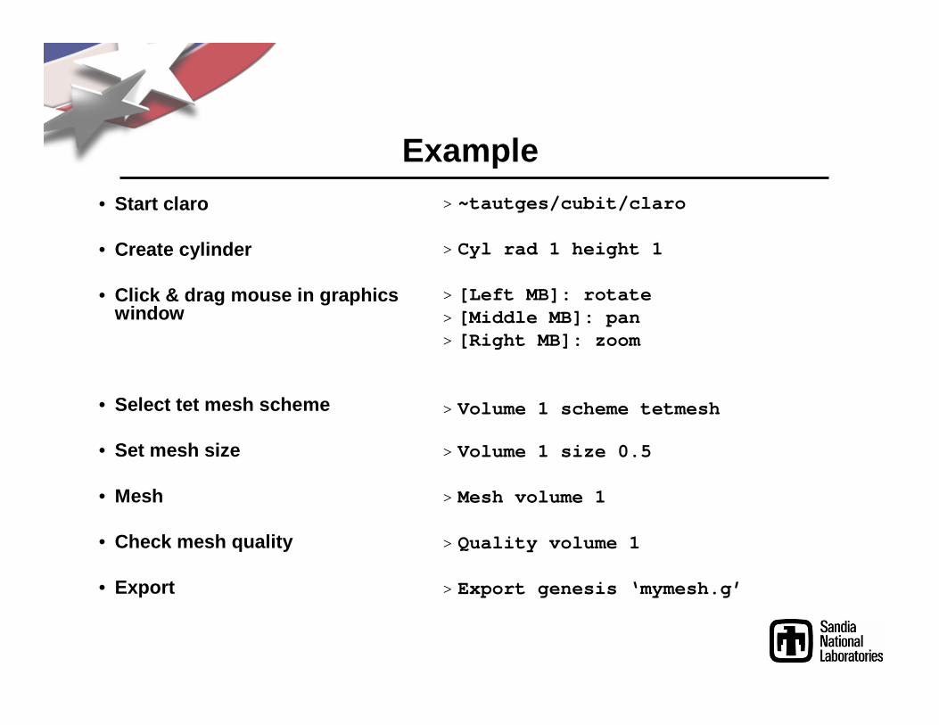
Example• Start claro
• Create cylinder
• Click & drag mouse in graphics window
• Select tet mesh scheme
• Set mesh size
• Mesh
• Check mesh quality
• Export
> ~tautges/cubit/claro
> Cyl rad 1 height 1
> [Left MB]: rotate> [Middle MB]: pan> [Right MB]: zoom
> Volume 1 scheme tetmesh
> Volume 1 size 0.5
> Mesh volume 1
> Quality volume 1
> Export genesis ‘mymesh.g’

Some More Useful CUBIT Commands
>List surface 3
• Pick geometry in graphics window– <Ctrl>-Left on geometry in graphics window
• Switch picking to entities of dimension 0/1/2/3– With mouse in graphics window, type 0/1/2/3
>Delete mesh
>Curve 3 size .2
• Set node-based BC group on 2 surfaces> Nodeset 100 surface 2 10
• Import solid model from file> Import acis
‘/pong/usr1/t/tautges/cubit/spindle.sat’

To Learn More…
• Plenty of small project topics for your final project
• If you’re interested in programming, also some hourly work I have
• Meshing Research Corner: http://www.andrew.cmu.edu/user/sowen/mesh.html
• Mesh Generation & Grid Generation on the Web: http://www-users.informatik.rwth-aachen.de/~roberts /meshgeneration.html
http://www.gotmesh.org

Next Time…
• Will learn more about how various meshing algorithms work
• Will mesh a simple example & transfer mesh to Ansys
• Next assignment:– Generate simple mesh w/Claro & analyze in Ansys