mesos storage series m4600h - hyperscalers...mesos storage series m4600h ultra density & fully...
TRANSCRIPT
MESOS Storage Series
M4600HUltra Density & Fully Redundant
4U Disk Expansion Unit
User's Guide
Date Modified: January 2, 2013 4:57 pm Document Version: 1.0.0
CONVENTIONS
VIII
Conventions
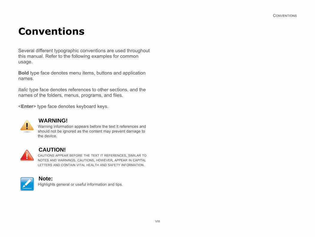
Several different typographic conventions are used throughout this manual. Refer to the following examples for common usage.
Bold type face denotes menu items, buttons and application names.
Italic type face denotes references to other sections, and the names of the folders, menus, programs, and files.
<Enter> type face denotes keyboard keys.
WARNING!Warning information appears before the text it references and should not be ignored as the content may prevent damage to the device.
CAUTION!CAUTIONS APPEAR BEFORE THE TEXT IT REFERENCES, SIMILAR TO NOTES AND WARNINGS. CAUTIONS, HOWEVER, APPEAR IN CAPITAL LETTERS AND CONTAIN VITAL HEALTH AND SAFETY INFORMATION.
Note:Highlights general or useful information and tips.
!
!
ACRONYMS
IX
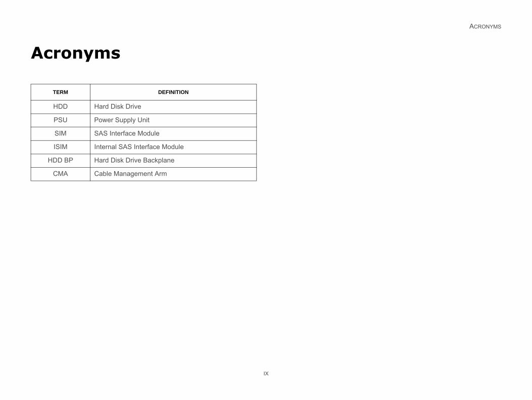
Acronyms
TERM DEFINITION
HDD Hard Disk Drive
PSU Power Supply Unit
SIM SAS Interface Module
ISIM Internal SAS Interface Module
HDD BP Hard Disk Drive Backplane
CMA Cable Management Arm
SAFETY INFORMATION
S
Im
Reaper
W
HeewheencthecomUsemalistimothe
SystheunpACing,
, devices and cables: Hazardous elec- present on power, telephone, and com- off the server and disconnect the nications systems, networks, and server before opening it. Otherwise,
ment damage can result.
e (ESD) and ESD protection: ESD can and other parts. We recommend that res in this chapter only at an ESD work-ilable, provide some ESD protection by ist strap attached to chassis ground any on the server when handling parts.
rds: Always handle boards carefully. sensitive to electrostatic discharge by their edges. After removing a board er or from the server, place the board grounded, static free surface. Use a vailable but not the board wrapper. Do surface.
jumpers: A jumper is a small plastic slips over two jumper pins. Some jump-top that can be gripped with fingertips dle nosed pliers. If the jumpers do not re when using needle nosed pliers to er; grip the narrow sides of the jumper
X
afety Information
portant Safety Instructions
d all caution and safety statements in this document before forming any of the instructions.
arnings
d safety instructions: Before working with the server, ther using this manual or any other resource as a refer-e, pay close attention to the safety instructions. Adhere to assembly instructions in this manual to ensure and maintain pliance with existing product certifications and approvals. only the described, regulated components specified in this
nual. Use of other products / components will void the UL ng and other regulatory approvals of the product and will st likely result in non-compliance with product regulations in region(s) in which the product is sold.
tem power on/off: The power button DOES NOT turn off system AC power. To remove power from system, you must lug the AC power cord from the wall outlet. Make sure the
power cord is unplugged before opening the chassis, add- or removing any components.
Hazardous conditionstrical conditions may bemunication cables. Turnpower cord, telecommumodems attached to thepersonal injury or equip
Electrostatic dischargdamage drives, boards,you perform all procedustation. If one is not avawearing an antistatic wrunpainted metal surface
ESD and handling boaThey can be extremely (ESD). Hold boards onlyfrom its protective wrappcomponent side up on aconductive foam pad if anot slide board over any
Installing or removingencased conductor thaters have a small tab on or with a pair of fine neehave such a tab, take caremove or install a jump
SAFETY INFORMATION
withcanproto grem
XI
the pliers, never the wide sides. Gripping the wide sides damage the contacts inside the jumper, causing intermittent blems with the function controlled by that jumper. Take care rip with, but not squeeze, the pliers or other tool used to ove a jumper, or the pins on the board may bend or break.
REVISION HISTORY
XII
Revision History
Refer to the table below for the updates made to this manual.
Copyright
Copyright © 2012 Quanta Computer Inc. This publication, including all photographs, illustrations and software, is pro-tected under international copyright laws, with all rights reserved. Neither this manual, nor any of the material contained herein, may be reproduced without the express written consent of the manufacturer. All trademarks and logos are copyrights of their respective owners.
Version 1.0 / January 9, 2013
Disclaimer
The information in this document is subject to change without notice. The manufacturer makes no representations or warran-ties with respect to the contents hereof and specifically dis-claims any implied warranties of merchantability or fitness for any particular purpose. Furthermore, the manufacturer reserves the right to revise this publication and to make changes from time to time in the content hereof without obligation of the man-ufacturer to notify any person of such revision or changes.
For the latest information and updates please refer to www.QuantaQCT.com
All the illustrations in this technical guide are for reference only and are subject to change without prior notice.
DATE CHAPTER UPDATES

About the M4600H
Chapter 1
ABO INTRODUCTION
1
Themoan tors
Thecian
Forww
Sy
Sp
Enc
4U
HD
6Gb
Hos
6Gb
edundancy
S Interface Module (SIM) (x2)
ernal SAS Interface Module (ISIM) (x4)
s)
nt main fans
each power supply unit
r supplies, 240 VAC
otification
UT THE M4600H
1-1
.1. Introduction
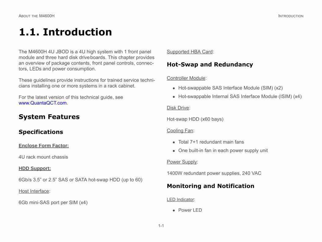
M4600H 4U JBOD is a 4U high system with 1 front panel dule and three hard disk drive boards. This chapter provides overview of package contents, front panel controls, connec-, LEDs and power consumption.
se guidelines provide instructions for trained service techni-s installing one or more systems in a rack cabinet.
the latest version of this technical guide, see w.QuantaQCT.com.
stem Features
ecifications
lose Form Factor:
rack mount chassis
D Support:
/s 3.5” or 2.5” SAS or SATA hot-swap HDD (up to 60)
t Interface:
mini-SAS port per SIM (x4)
Supported HBA Card:
Hot-Swap and R
Controller Module:
Hot-swappable SA
Hot-swappable Int
Disk Drive:
Hot-swap HDD (x60 bay
Cooling Fan:
Total 7+1 redunda
One built-in fan in
Power Supply:
1400W redundant powe
Monitoring and N
LED Indicator:
Power LED
ABO INTRODUCTION
Firm
SC
OS
Sy
Dim
Wit
Wit
We
Wih
F)
ity
UT THE M4600H
1-2
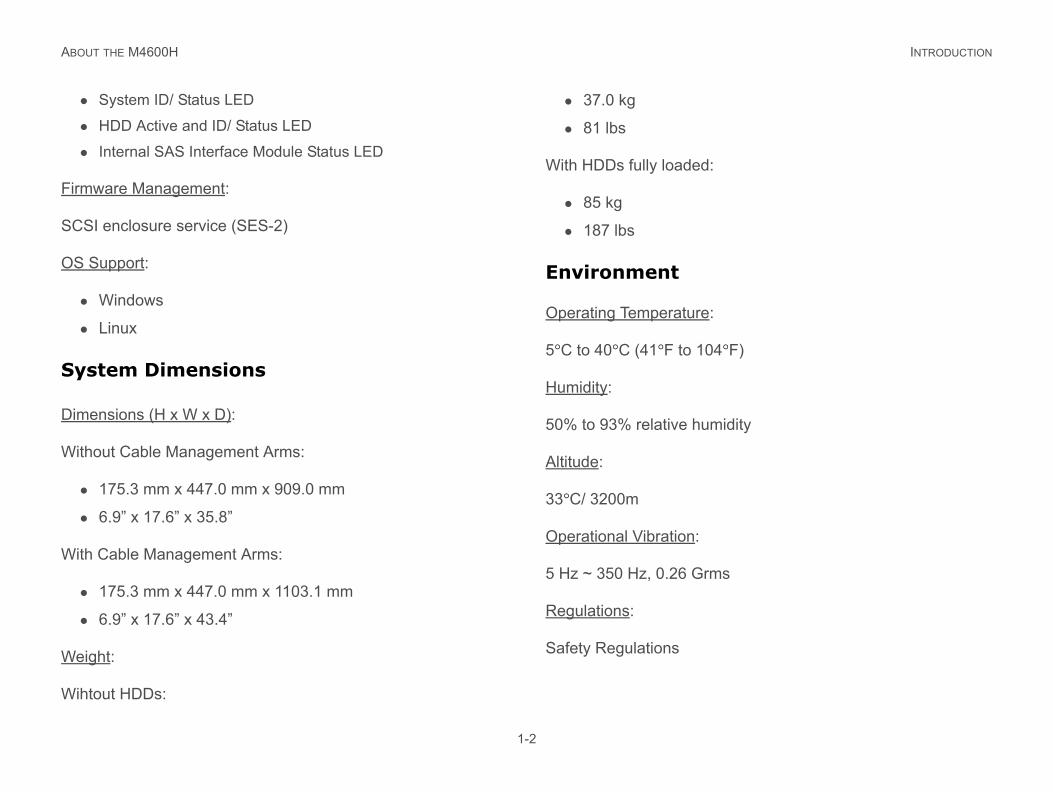
System ID/ Status LED
HDD Active and ID/ Status LED
Internal SAS Interface Module Status LED
ware Management:
SI enclosure service (SES-2)
Support:
Windows
Linux
stem Dimensions
ensions (H x W x D):
hout Cable Management Arms:
175.3 mm x 447.0 mm x 909.0 mm
6.9” x 17.6” x 35.8”
h Cable Management Arms:
175.3 mm x 447.0 mm x 1103.1 mm
6.9” x 17.6” x 43.4”
ight:
tout HDDs:
37.0 kg
81 lbs
With HDDs fully loaded:
85 kg
187 lbs
Environment
Operating Temperature:
5°C to 40°C (41°F to 104°
Humidity:
50% to 93% relative humid
Altitude:
33°C/ 3200m
Operational Vibration:
5 Hz ~ 350 Hz, 0.26 Grms
Regulations:
Safety Regulations
ABOUT THE M4600H PACKAGE CONTENTS
1-3
1.2. Package Contents
1 x JBOD storage system
2 x power cord
1 x mini-USB cable
Rail kit
Cable management arm
ABO A TOUR OF THE SYSTEM
1
TheM4
Sy
Co
erview
COMPONENT
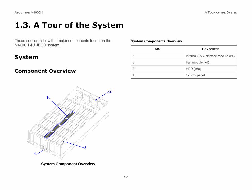
Internal SAS interface module (x4)
Fan module (x4)
HDD (x60)
Control panel
UT THE M4600H
1-4
.3. A Tour of the System
se sections show the major components found on the 600H 4U JBOD system.
stem
mponent Overview
System Component Overview
Sys
5
4
3
2
1
12
34
System Components Ov
NO.
1
2
3
4
ABO COMPONENT PLACEMENT
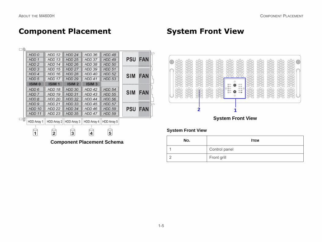
Co t View
stem Front View
ITEM
rol panel
t grill
5
4
3
2
1
1
UT THE M4600H
1-5
mponent Placement
Component Placement Schema
System Fron
Sy
HDD 0HDD 1HDD 2HDD 3HDD 4HDD 5
HDD 12HDD 13HDD 14HDD 15HDD 16HDD 17
HDD 6HDD 7HDD 8HDD 9HDD 10HDD 11
HDD 18HDD 19HDD 20HDD 21HDD 22HDD 23
HDD 24HDD 25HDD 26HDD 27HDD 28HDD 29
HDD 30HDD 31HDD 32HDD 33HDD 34HDD 35
HDD 36HDD 37HDD 38HDD 39HDD 40HDD 41
HDD 42HDD 43HDD 44HDD 45HDD 46HDD 47
HDD 48HDD 49HDD 50HDD 51HDD 52HDD 53
HDD 54HDD 55HDD 56HDD 57HDD 59HDD 59
PSU
SIM
SIM
PSU
FAN
FAN
FAN
FAN
HDD 0HDD 1HDD 2HDD 3HDD 4HDD 5
HDD 6HDD 7HDD 8HDD 9HDD 10HDD 11
HDD 12HDD 13HDD 14HDD 15HDD 16HDD 17
HDD 18HDD 19HDD 20HDD 21HDD 22HDD 23
HDD 24HDD 25HDD 26HDD 27HDD 28HDD 29
HDD 30HDD 31HDD 32HDD 33HDD 34HDD 35
HDD 48HDD 49HDD 50HDD 51HDD 52HDD 53
HDD 54HDD 55HDD 56HDD 57HDD 59HDD 59
HDD 36HDD 37HDD 38HDD 39HDD 40HDD 41
HDD 42HDD 43HDD 44HDD 45HDD 46HDD 47
HDD Array 1 HDD Array 2 HDD Array 3 HDD Array 4 HDD Array 5
54321
ISIM 0 ISIM 1 ISIM 2 ISIM 3
System Front View
NO.
1 Cont
2 Fron
2
ABO SYSTEM FRONT VIEW
Co
Co
1
1
1
1
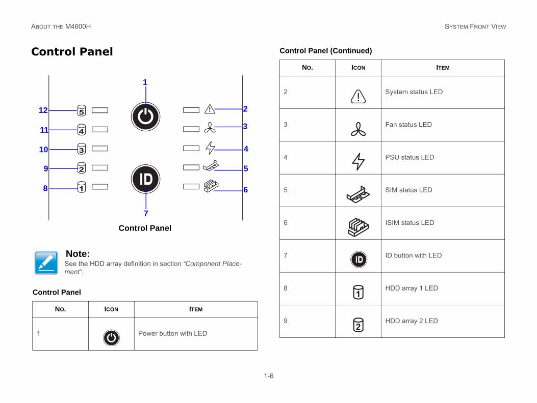
System status LED
Fan status LED
PSU status LED
SIM status LED
ISIM status LED
ID button with LED
HDD array 1 LED
HDD array 2 LED
d)
ITEM
UT THE M4600H
1-6
ntrol Panel
Control Panel
Note:See the HDD array definition in section “Component Place-ment”.
ntrol Panel
NO. ICON ITEM
Power button with LED
5
4
3
2
1
1
2
3
4
5
6
7
8
9
0
1
2
2
3
4
5
6
7
8
9
Control Panel (Continue
NO. ICON
1
2
ABO SYSTEM REAR VIEW
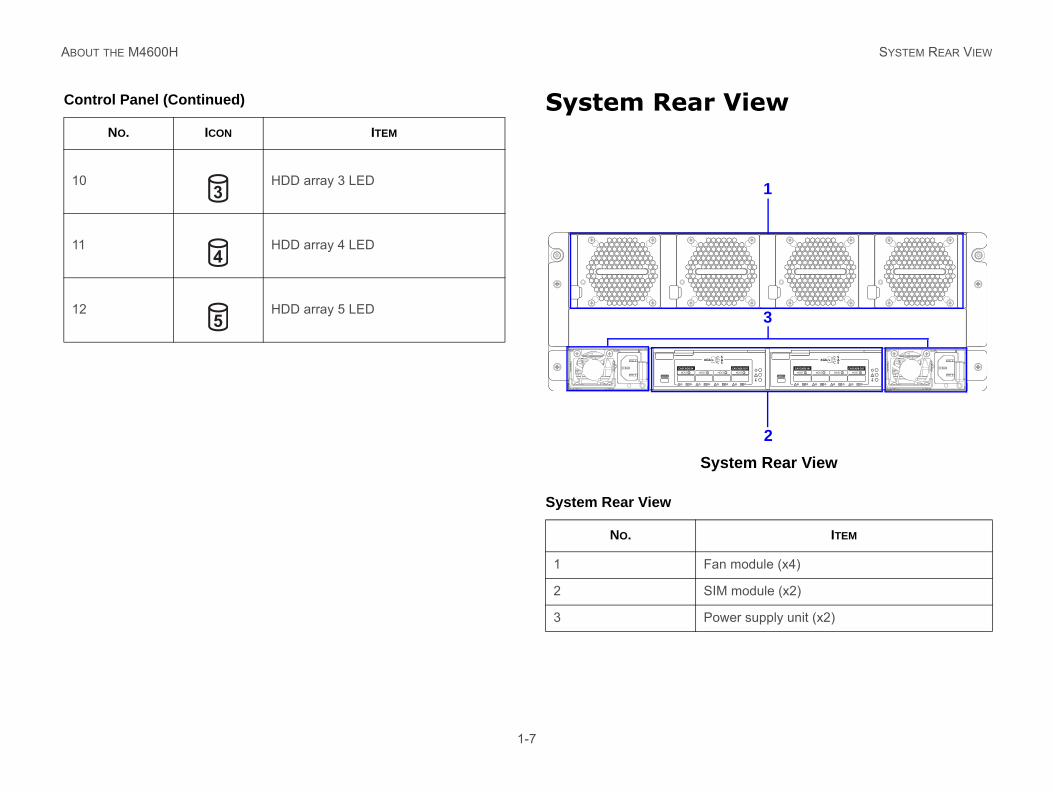
View
ystem Rear View
10
11
12
Co
ITEM
an module (x4)
IM module (x2)
ower supply unit (x2)
/sSAS
CASCADE OUT
HOST 2 HOST 3SERVICE
6Gb/sSAS
CASCADE IN CASCADE OUT
HOST 0 HOST 1 HOST 2 HOST 3
1
2
3
UT THE M4600H
1-7
System Rear
S
HDD array 3 LED
HDD array 4 LED
HDD array 5 LED
ntrol Panel (Continued)
NO. ICON ITEM
3
4
5
System Rear View
NO.
1 F
2 S
3 P
SERVICE
6Gb
CASCADE IN
HOST 0 HOST 1
ABO SYSTEM REAR VIEW
SI
SIM
1
2
3
SE
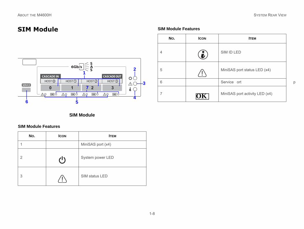
SIM ID LED
MiniSAS port status LED (x4)
Service port
MiniSAS port activity LED (x4)
ITEM
UT THE M4600H
1-8
M Module
SIM Module
Module Features
NO. ICON ITEM
MiniSAS port (x4)
System power LED
SIM status LED
RVICE
6Gb/sSAS
CASCADE IN CASCADE OUT
HOST 0 HOST 1 HOST 2 HOST 3
0 1 2 3
12
3
456
7
4
5
6
7
SIM Module Features
NO. ICON
OK
ABO LED STATUS DEFINITIONS
LE
TheLED
ITION DESCRIPTION
Fro
System power on
System power off
Enclosure identifier, not identified
Not identified
System fault
System good
Fan fault
Fan good
PSU fault
PSU good
SIM fault
SIM good
ISIM fault
ISIM good
HDD row# fault
HDD row# good
UT THE M4600H
1-9
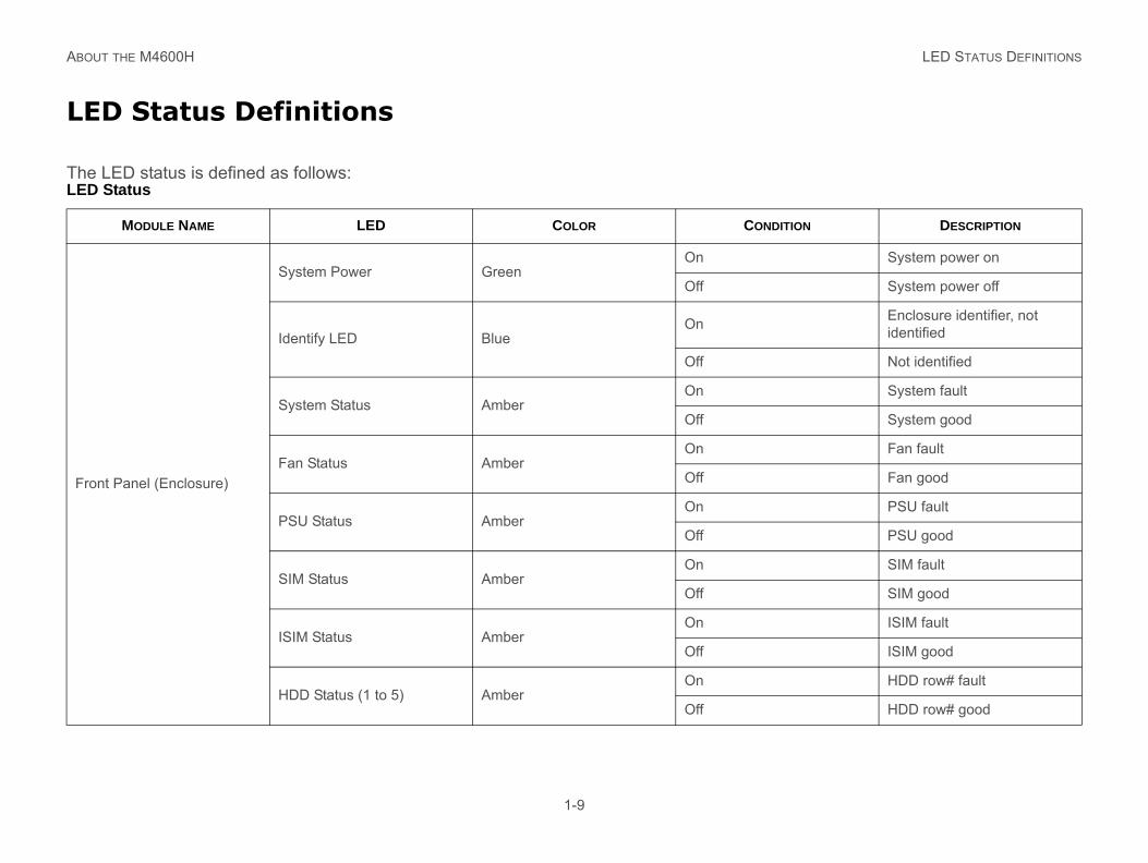
D Status Definitions
LED status is defined as follows: Status
MODULE NAME LED COLOR COND
nt Panel (Enclosure)
System Power GreenOn
Off
Identify LED BlueOn
Off
System Status AmberOn
Off
Fan Status AmberOn
Off
PSU Status AmberOn
Off
SIM Status AmberOn
Off
ISIM Status AmberOn
Off
HDD Status (1 to 5) AmberOn
Off
ABO LED STATUS DEFINITIONS
Ha
HDD ready for access
During spin up or accessing HDDs
HDD not ready
HDD identifier
Ready for remove
Normal
Hard drive failed or port dis-able
Normal
Hot spare indicator is turned on
Consistency check In prog-ress indicator is turned on
Rebuild/remap indicator is turned on
Poule
SPS failed
SPS healthy
Any fan failure
All fans healthy
LED
ITION DESCRIPTION
UT THE M4600H
1-10
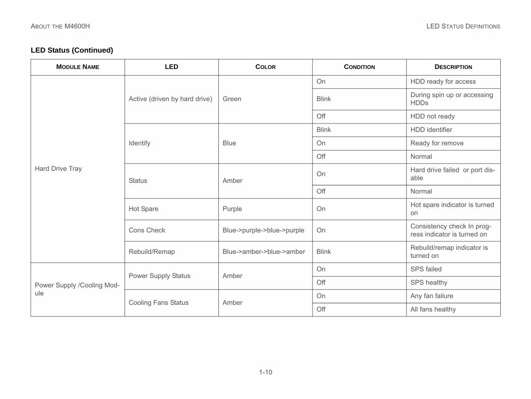
rd Drive Tray
Active (driven by hard drive) Green
On
Blink
Off
Identify Blue
Blink
On
Off
Status AmberOn
Off
Hot Spare Purple On
Cons Check Blue->purple->blue->purple On
Rebuild/Remap Blue->amber->blue->amber Blink
wer Supply /Cooling Mod-Power Supply Status Amber
On
Off
Cooling Fans Status AmberOn
Off
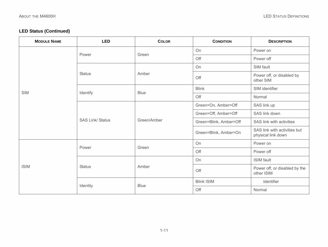
Status (Continued)
MODULE NAME LED COLOR COND
ABO LED STATUS DEFINITIONS
SIM
Power on
Power off
SIM fault
Power off, or disabled by other SIM
SIM identifier
Normal
ber=Off SAS link up
ber=Off SAS link down
mber=Off SAS link with activities
mber=On SAS link with activities but physical link down
ISI
Power on
Power off
ISIM fault
Power off, or disabled by the other ISIM
identifier
Normal
LED
ITION DESCRIPTION
UT THE M4600H
1-11
Power GreenOn
Off
Status AmberOn
Off
Identify BlueBlink
Off
SAS Link/ Status Green/Amber
Green=On, Am
Green=Off, Am
Green=Blink, A
Green=Blink, A
M
Power GreenOn
Off
Status AmberOn
Off
Identity BlueBlink ISIM
Off
Status (Continued)
MODULE NAME LED COLOR COND
ABO LED STATUS DEFINITIONS
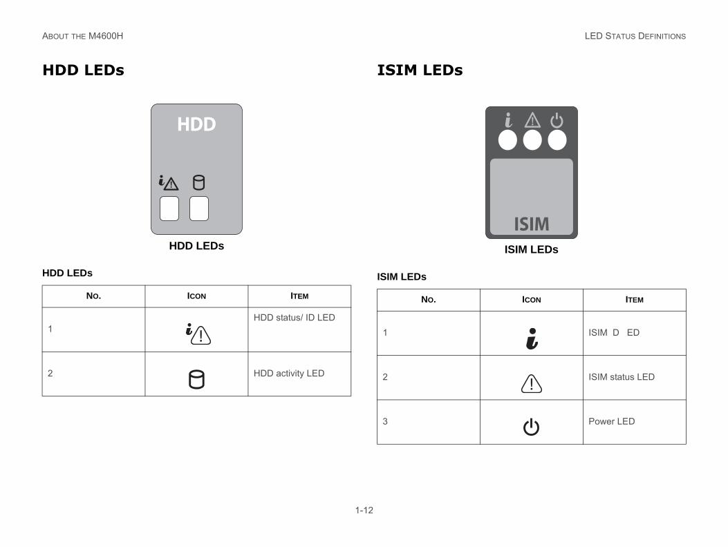
HD
ISIM LEDs
HDD
1
2
ICON ITEM
ISIM ID LED
ISIM status LED
Power LED
ISIM
UT THE M4600H
1-12
D LEDs
HDD LEDs
ISIM LEDs
LEDs
NO. ICON ITEM
HDD status/ ID LED
HDD activity LED
HDD
ISIM LEDs
NO.
1
2
3

Safety Information
Chapter 2
SAF SERVER SAFETY INFORMATION
2
To requingsing
In tmesitepre
Youcall
Youbly comUseguiding resreg
ings and Cautions
or property damage, before you begin ad, observe, and adhere to all of the fol-s and information. The following safety roughout the documentation and may ct and / or the product packaging.
ates the presence of a hazard that may cause r personal injury or property damage if the TION is ignored.
ates the presence of a hazard that may result rious personal injury if the WARNING is ed.
ates potential hazard if indicated information is ed.
ates shock hazards that result in serious injury ath if safety instructions are not followed.
ates hot components or surfaces.
ETY INFORMATION
2-1
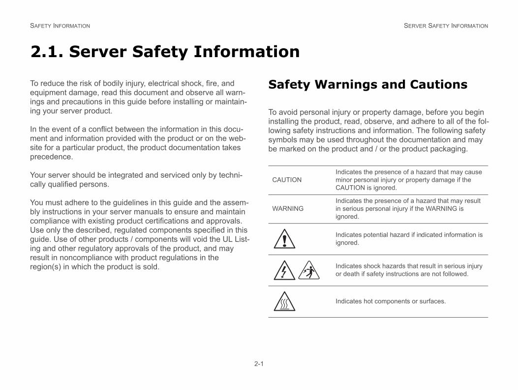
.1. Server Safety Information
educe the risk of bodily injury, electrical shock, fire, and ipment damage, read this document and observe all warn- and precautions in this guide before installing or maintain-your server product.
he event of a conflict between the information in this docu-nt and information provided with the product or on the web- for a particular product, the product documentation takes cedence.
r server should be integrated and serviced only by techni-y qualified persons.
must adhere to the guidelines in this guide and the assem-instructions in your server manuals to ensure and maintain pliance with existing product certifications and approvals. only the described, regulated components specified in this e. Use of other products / components will void the UL List-and other regulatory approvals of the product, and may ult in noncompliance with product regulations in the ion(s) in which the product is sold.
Safety Warn
To avoid personal injuryinstalling the product, relowing safety instructionsymbols may be used thbe marked on the produ
CAUTIONIndicminoCAU
WARNINGIndicin seignor
Indicignor
Indicor de
Indic
SAF INTENDED APPLICATION USES
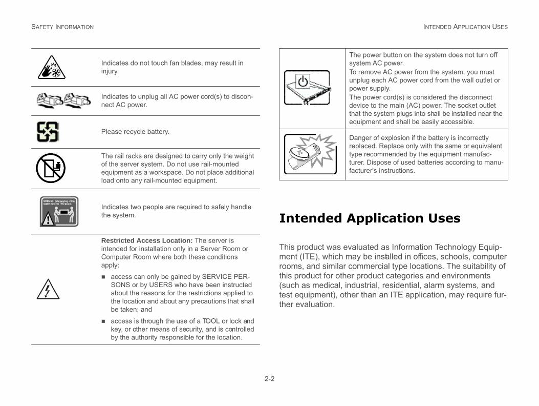
plication Uses
ted as Information Technology Equip-e installed in offices, schools, computer
mercial type locations. The suitability of duct categories and environments
trial, residential, alarm systems, and an an ITE application, may require fur-
ower button on the system does not turn off m AC power.move AC power from the system, you must g each AC power cord from the wall outlet or r supply.ower cord(s) is considered the disconnect e to the main (AC) power. The socket outlet he system plugs into shall be installed near the ment and shall be easily accessible.
er of explosion if the battery is incorrectly ced. Replace only with the same or equivalent recommended by the equipment manufac- Dispose of used batteries according to manu-rer's instructions.
ETY INFORMATION
2-2
Intended Ap
This product was evaluament (ITE), which may brooms, and similar comthis product for other pro(such as medical, industest equipment), other thther evaluation.
Indicates do not touch fan blades, may result in injury.
Indicates to unplug all AC power cord(s) to discon-nect AC power.
Please recycle battery.
The rail racks are designed to carry only the weight of the server system. Do not use rail-mounted equipment as a workspace. Do not place additional load onto any rail-mounted equipment.
Indicates two people are required to safely handle the system.
Restricted Access Location: The server is intended for installation only in a Server Room or Computer Room where both these conditions apply:
access can only be gained by SERVICE PER-SONS or by USERS who have been instructed about the reasons for the restrictions applied to the location and about any precautions that shall be taken; and
access is through the use of a TOOL or lock and key, or other means of security, and is controlled by the authority responsible for the location.
The psysteTo reunplupoweThe pdevicthat tequip
Dangreplatype turer.factu
SAF SITE SELECTION
Si
Theme
andling Practices
nal injury or equipment damage:
ccupational health and safety require-g and lifting equipment.
sistance or other suitable assistance lifting equipment.
ht for easier handling, remove any eas-ponents.
ETY INFORMATION
2-3
te Selection
system is designed to operate in a typical office environ-nt. Choose a site that is:
Clean, dry, and free of airborne particles (other than nor-mal room dust).
Well-ventilated and away from sources of heat including direct sunlight and radiators.
Away from sources of vibration or physical shock.
Isolated from strong electromagnetic fields produced by electrical devices.
In regions that are susceptible to electrical storms, we rec-ommend you plug your system into a surge suppressor and disconnect telecommunication lines to your modem during an electrical storm.
Provided with a properly grounded wall outlet.
Provided with sufficient space to access the power supply cord(s), because they serve as the product's main power disconnect.
Provided with either two independent AC power sources or two independent phases from a s single source.
Equipment H
Reduce the risk of perso
Conform to local oments when movin
Use mechanical aswhen moving and
To reduce the weigily detachable com
SAF POWER AND ELECTRICAL WARNINGS
Po
arnings
s not provided with your product, pur-ved for use in your country.
A HOT-PLUG POWER SUPPLY, UNPLUG THE HE POWER SUPPLY BEING REPLACED BEFORE THE SERVER.
AL SHOCK OR FIRE, CHECK THE POWER CORD(S) D WITH THE PRODUCT AS FOLLOWS:
t to modify or use the AC power cord(s) if they act type required to fit into the grounded elec-
rd(s) must meet the following criteria: The st have an electrical rating that is greater than
ctrical current rating marked on the product.
MUST HAVE SAFETY GROUND PIN OR CONTACT FOR THE ELECTRICAL OUTLET.
LY CORD(S) IS / ARE THE MAIN DISCONNECT ER. THE SOCKET OUTLET(S) MUST BE NEAR THE
EADILY ACCESSIBLE FOR DISCONNECTION.
ETY INFORMATION
2-4
wer and Electrical Warnings
Power Cord W
If an AC power cord wachase one that is appro
CAUTION!THE POWER BUTTON, INDICATED BY THE STAND-BY POWER MARK-ING, DOES NOT COMPLETELY TURN OFF THE SYSTEM AC POWER, 5V STANDBY POWER IS ACTIVE WHENEVER THE SYSTEM IS PLUGGED IN. TO REMOVE POWER FROM SYSTEM, YOU MUST UNPLUG THE AC POWER CORD FROM THE WALL OUTLET. YOUR SYSTEM MAY USE MORE THAN ONE AC POWER CORD. MAKE SURE ALL AC POWER CORDS ARE UNPLUGGED. MAKE SURE THE AC POWER CORD(S) IS / ARE UNPLUGGED BEFORE YOU OPEN THE CHASSIS, OR ADD OR REMOVE ANY NON HOT-PLUG COMPONENTS.
CAUTION!DO NOT ATTEMPT TO MODIFY OR USE AN AC POWER CORD IF IT IS NOT THE EXACT TYPE REQUIRED. A SEPARATE AC CORD IS REQUIRED FOR EACH SYSTEM POWER SUPPLY.
CAUTION!THE POWER SUPPLY IN THIS PRODUCT CONTAINS NO USER-SER-VICEABLE PARTS. DO NOT OPEN THE POWER SUPPLY. HAZARDOUS VOLTAGE, CURRENT AND ENERGY LEVELS ARE PRESENT INSIDE THE POWER SUPPLY. RETURN TO MANUFACTURER FOR SERVICING.
CAUTION!WHEN REPLACING A HOT-PLUG POWER SUPPLY, UNPLUG THE POWER CORD TO THE POWER SUPPLY BEING REPLACED BEFORE REMOVING IT FROM THE SERVER.
!
!
!
!
CAUTION!WHEN REPLACINGPOWER CORD TO TREMOVING IT FROM
CAUTION!TO AVOID ELECTRICTHAT WILL BE USE
Do not attempare not the extrical outlets.
The power copower cord muthat of the ele
CAUTION!THE POWER CORDTHAT IS SUITABLE
CAUTION!THE POWER SUPPDEVICE TO AC POWEQUIPMENT AND R
!
!
!
!
SAF SYSTEM ACCESS WARNINGS
ss Warnings
AL INJURY OR PROPERTY DAMAGE, THE FOLLOW-UCTIONS APPLY WHENEVER ACCESSING THE
DUCT:
ripheral devices connected to this product.
stem by pressing the power button to off.
e AC power by unplugging all AC power cords m or wall outlet.
cables and telecommunication lines that are he system.
ws or other fasteners when removing access completion of accessing inside the product, s cover with original screws or fasteners.
the inside of the power supply. There are no rts in the power supply. Return to manufac-ing.
he server and disconnect all power cords or replacing any non hot-plug component.
g a hot-plug power supply, unplug the power wer supply being replaced before removing ply from the server.
ETY INFORMATION
2-5
System AcceCAUTION!THE POWER SUPPLY CORD(S) MUST BE PLUGGED INTO SOCKET-OUTLET(S) THAT IS /ARE PROVIDED WITH A SUITABLE EARTH GROUND.
!CAUTION!TO AVOID PERSONING SAFETY INSTRINSIDE OF THE PRO
Turn off all pe
Turn off the sy
Disconnect thfrom the syste
Disconnect allconnected to t
Retain all screcover(s). Uponrefasten acces
Do not accessserviceable paturer for servic
Power down tbefore adding
When replacincord to the pothe power sup
!
SAF RACK MOUNT WARNINGS
Ra
Themaa ra
Thepormeacc
Instest
Ext
installing a main power disconnect for main disconnect must be readily
be labeled as controlling power to the e server(s).
l electric shock, a proper safety ground r the rack and each piece of equipment
bient - If installed in a closed or multi-operating ambient temperature of the e greater than room ambient. There-ld be given to installing the equipment atible with the maximum ambient tem-
d by the manufacturer.
allation of the equipment in a rack amount of air flow required for safe ent is not compromised.
ounting of the equipment in the rack azardous condition is not achieved due ading.
nsideration should be given to the con-t to the supply circuit and the effect that its might have on overcurrent protection opriate consideration of equipment ld be used when addressing this con-
ETY INFORMATION
2-6
ck Mount Warnings
following installation guidelines are required by UL for intaining safety compliance when installing your system into ck.
equipment rack must be anchored to an unmovable sup-t to prevent it from tipping when a server or piece of equip-nt is extended from it. The equipment rack must be installed ording to the rack manufacturer's instructions.
all equipment in the rack from the bottom up, with the heavi-equipment at the bottom of the rack.
end only one piece of equipment from the rack at a time.
You are responsible for the entire rack unit. Thisaccessible, and it must entire unit, not just to th
To avoid risk of potentiamust be implemented foinstalled in it.
Elevated Operating Amunit rack assembly, the rack environment may bfore, consideration shouin an environment compperature (Tma) specifie
Reduced Air Flow - Instshould be such that theoperation of the equipm
Mechanical Loading - Mshould be such that a hto uneven mechanical lo
Circuit Overloading - Conection of the equipmenoverloading of the circuand supply wiring. Apprnameplate ratings shoucern.
CAUTION!UNLESS YOU ARE ADDING OR REMOVING A HOT-PLUG COMPONENT, ALLOW THE SYSTEM TO COOL BEFORE OPENING THE COVERS. TO AVOID THE POSSIBILITY OF COMING INTO CONTACT WITH HOT COM-PONENT(S) DURING A HOT-PLUG INSTALLATION, BE CAREFUL WHEN REMOVING OR INSTALLING THE HOT-PLUG COMPONENT(S).
CAUTION!TO AVOID INJURY DO NOT CONTACT MOVING FAN BLADES. IF YOUR SYSTEM IS SUPPLIED WITH A GUARD OVER THE FAN, DO NOT OPER-ATE THE SYSTEM WITHOUT THE FAN GUARD IN PLACE.
!
!
SAF ELECTROSTATIC DISCHARGE (ESD)
Relme
Parthastrip
El
AlwtiveboaboaUseper
s
ement
GER OF EXPLOSION IF THE BATTERY IS INCOR-. WHEN REPLACING THE BATTERY, USE ONLY THE ENDED BY THE EQUIPMENT MANUFACTURER.
RIES ACCORDING TO LOCAL ORDINANCES AND
TO RECHARGE A BATTERY.
TO DISASSEMBLE, PUNCTURE, OR OTHERWISE Y.
ETY INFORMATION
2-7
iable Earthing - Reliable earthing of rack-mounted equip-nt should be maintained.
ticular attention should be given to supply connections other n direct connections to the branch circuit (e.g. use of power s).
ectrostatic Discharge (ESD)
ays handle boards carefully. They can be extremely sensi- to ESD. Hold boards only by their edges. After removing a rd from its protective wrapper or from the server, place the rd component side up on a grounded, static free surface. a conductive foam pad if available but not the board wrap-
. Do not slide board over any surface.
Other Hazard
Battery Replac
CAUTION!ESD CAN DAMAGE DRIVES, BOARDS, AND OTHER PARTS. WE REC-OMMEND THAT YOU PERFORM ALL PROCEDURES AT AN ESD WORK-STATION. IF ONE IS NOT AVAILABLE, PROVIDE SOME ESD PROTECTION BY WEARING AN ANTISTATIC WRIST STRAP ATTACHED TO CHASSIS GROUND -- ANY UNPAINTED METAL SURFACE -- ON YOUR SERVER WHEN HANDLING PARTS.
!
CAUTION!THERE IS THE DANRECTLY REPLACEDBATTERY RECOMM
CAUTION!DISPOSE OF BATTEREGULATIONS.
CAUTION!DO NOT ATTEMPT
CAUTION!DO NOT ATTEMPT DAMAGE A BATTER
!
!
!
!
SAF OTHER HAZARDS
Co
ETY INFORMATION
2-8
oling and Airflow
CAUTION!CAREFULLY ROUTE CABLES AS DIRECTED TO MINIMIZE AIRFLOW BLOCKAGE AND COOLING PROBLEMS. FOR PROPER COOLING AND AIRFLOW, OPERATE THE SYSTEM ONLY WITH THE CHASSIS COVERS INSTALLED. OPERATING THE SYSTEM WITHOUT THE COVERS IN PLACE CAN DAMAGE SYSTEM PARTS. TO INSTALL THE COVERS:
Check first to make sure you have not left loose tools or parts inside the system.
Check that cables, add-in cards, and other components are properly installed.
Attach the covers to the chassis according to the product instructions.
!
Regulatory and Compliance Infor-mation
Chapter 3
REGULATORY AND COMPLIANCE INFORMATION PRODUCT REGULATORY COMPLIANCE MARKINGS
3-1
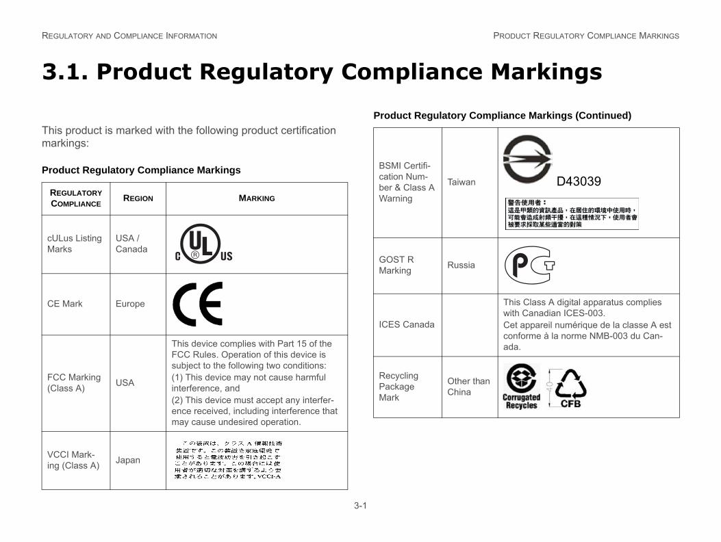
3.1. Product Regulatory Compliance Markings
This product is marked with the following product certification markings:
Product Regulatory Compliance Markings
REGULATORY COMPLIANCE
REGION MARKING
cULus Listing Marks
USA / Canada
CE Mark Europe
FCC Marking (Class A) USA
This device complies with Part 15 of the FCC Rules. Operation of this device is subject to the following two conditions:(1) This device may not cause harmful interference, and(2) This device must accept any interfer-ence received, including interference that may cause undesired operation.
VCCI Mark-ing (Class A) Japan
BSMI Certifi-cation Num-ber & Class A Warning
Taiwan D43039
GOST R Marking Russia
ICES Canada
This Class A digital apparatus complies with Canadian ICES-003.Cet appareil numérique de la classe A est conforme à la norme NMB-003 du Can-ada.
Recycling Package Mark
Other than China
Product Regulatory Compliance Markings (Continued)
REG ELECTROMAGNETIC COMPATIBILITY NOTICES
3 otices
FC(U
Thiis snotanycau
ThilimiFCCprotionquethemuwillcauwhitheor m
ment to an outlet on a circuit other than e receiver is connected.
or an experienced radio/TV technician
ations not expressly approved by the uld void the user's authority to operate
tomer is responsible for ensuring com-roduct.
uter input/output devices, terminals, ly with FCC Class A or B limits may be r product. Operation with noncompliant sult in interference to radio and TV
ct to peripherals must be shielded and th cables, connected to peripherals, that unded may result in interference to
ULATORY AND COMPLIANCE INFORMATION
3-2
.2. Electromagnetic Compatibility N
C Verification Statement SA)
s device complies with Part 15 of the FCC Rules. Operation ubject to the following two conditions: (1) this device may cause harmful interference, and (2) this device must accept interference received, including interference that may se undesired operation.
s equipment has been tested and found to comply with the ts for a Class A digital device, pursuant to Part 15 of the
Rules. These limits are designed to provide reasonable tection against harmful interference in a residential installa-. This equipment generates, uses, and can radiate radio fre-ncy energy and, if not installed and used in accordance with instructions, may cause harmful interference to radio com-nications. However, there is no guarantee that interference not occur in a particular installation. If this equipment does se harmful interference to radio or television reception, ch can be determined by turning the equipment off and on, user is encouraged to try to correct the interference by one
ore of the following measures:
Reorient or relocate the receiving antenna.
Increase the separation between the equipment and the receiver
Connect the equipthe one to which th
Consult the dealerfor help.
Any changes or modificgrantee of this device cothe equipment. The cuspliance of the modified p
Only peripherals (compprinters, etc.) that compattached to this computeperipherals is likely to rereception.
All cables used to connegrounded. Operation wiare not shielded and groradio and TV reception.
REG EUROPE (CE DECLARATION OF CONFORMITY)
Eufo
Thiwith(89to il
VC
Eng
ThitaryTecrecencma
n)
arking and EMC warning is located on the product
ecified Components
g and compliance to other regulatory larations, the following regulated com-nd conditions adhered to. Interchanging nt will void the UL listing and other
d approvals.
ation for configurations can be found on URL: http://www.QuantaQCT.com
ss to the Web address, please contact .
t have a printed wiring board flammabil-m UL94V-1. Add-in cards containing nectors and/or lithium batteries must
or UL listed. Any add-in card containing
ULATORY AND COMPLIANCE INFORMATION
3-3
rope (CE Declaration of Con-rmity)
s product has been tested in accordance too, and complies the Low Voltage Directive (73/23/EEC) and EMC Directive
/336/EEC). The product has been marked with the CE Mark lustrate its compliance.
CI (Japan)
lish translation of the notice above:
s is a Class A product based on the standard of the Volun- Control Council for Interference (VCCI) from Information hnology Equipment. If this is used near a radio or television eiver in a domestic environment, it may cause radio interfer-e. Install and use the equipment according to the instruction nual.
BSMI (Taiwa
The BSMI Certification Mthe outside rear area of
Regulated Sp
To maintain the UL listincertifications and/or decponents must be used aor use of other componeproduct certifications an
Updated product informthe site at the following
If you do not have acceyour local representative
Add-in cards: musity rating of minimuexternal power conbe UL recognized
REG F HAZARDOUS SUBSTANCES (ROHS) COMPLIANCE
Rest
Quaof btivemaappexe
RoHcha
Thr
omium
Biphenyls Diphenyl Ethers (PBDE)
01% by mass (100 PPM) for:
Product Recycling
nd-of-life take-back systems and untry. Contact the retailer or distributor ation about product recycling and / or
ULATORY AND COMPLIANCE INFORMATION RESTRICTION O
3-4
modem telecommunication circuitry must be UL listed. In addition, the modem must have the appropriate telecom-munications, safety, and EMC approvals for the region in which it is sold.
Peripheral Storage Devices: must be UL recognized or UL listed accessory and TUV or VDE licensed. Maximum power rating of any one device is 19 watts. Total server configuration is not to exceed the maximum loading condi-tions of the power supply.
striction of Hazardous Sub-ances (RoHS) Compliance
nta® Computer Inc. has a system in place to restrict the use anned substances in accordance with the European Direc- 2002/95/EC. Compliance is based on declaration that terials banned in the RoHS Directive are either (1) below all licable threshold limits or (2) an approved / pending RoHS mption applies.
S implementation details are not fully defined and may nge.
eshold limits and banned substances are noted below:
Quantity limit of 0.1% by mass (1000 PPM) for:
Lead
Mercury
Hexavalent Chr
Polybrominated
Quantity limit of 0.
Cadmium
End of Life /
Product recycling and erequirements vary by coof this product for informtake-back.