met 330: fluid mechanics 0. ayala spring 2017 … · applied fluid mechanics 7 th edition by robert...
TRANSCRIPT

Team 7 Continental AG proposal
MET 330: Fluid Mechanics
0. Ayala
Spring 2017 Project
Tasks 1-9 submission
Team 7
Eric Stone
Sylvia Homes-Caldwell
Nathan Williamson
links
Task l
Purpose: According to the problem description we are required to have three different tanks; an operating tank, a storage tank, and a dirty fluid tank.
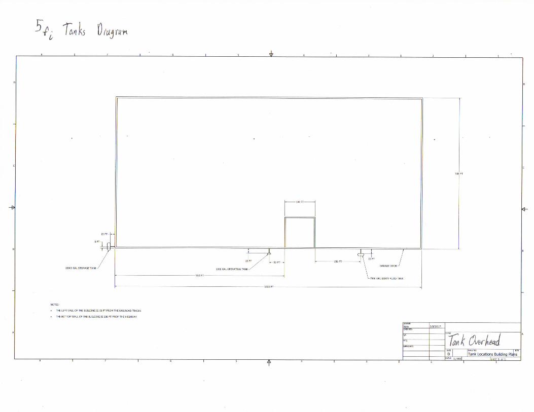
Diagrams: See following overhead tank view.
Sources: Mott, R. Untener, J.A., "Applied Fluid Mechanics", 7 t h ed. Pearson Education, Inc, (2015).
http://www.engineeringtoolboxxoni/fuel-oil"Storage-tanks~dimensioiis-d 1585 .html
Design Considerations: Since we are designing this system to work in the real world, we decided to try and find a supplier for most of our parts. We found our tank dimensions from the referenced website.
After finding this website we agreed to make each tank a cylindrical shaped tank.
Data/variables:
1,000 gal. operating tank: Diameter = 48in Length = 10ft lOin
15,000 gal. holding tank: Diameter = 120in Length = 25ft 6in
7,500 gal. dirty fluid tank: Diameter = 96in Length = 19ft 8in
Procedure: With placing each tank we thought it would be best to locate them where they will be put to use. The storage tank was placed by the railroad tracks, the operating tank was placed close to the machining area, and the dirty fluid tank was placed close to the driveway.
Calculations: The dimensions for the given size tanks are supplied from the manufacturer
Summary: The listed tanks have been chosen as the minimum sizes necessary for operation of the system.
Materials: 1,000 gal. operating tank, 15,000 gal. holding tank, 7,500 gal. dirty fluid tank
Analysis: Since we were allowed some freedom with the building plans, we moved the driveway towards the right side of the building where it was originally placed in figure 1 of our project packet. We then assumed a building size of 500 ft x 1,000 ft.
Group Project
Task 2
Purpose
One of the first steps to designing a good pipe system is selecting the tank material and specify
the wall thickness of the storage tanks.
Sources
Applied Fluid Mechanics 7 t h edition by Robert L . Mott and Joseph A. Untener
Design Considerations
The locations of the tanks and how they are place around the building. While also taking in to
account how far apart each is and if they are grouped together. These design considerations were
determined in task one.
Data and Variables
Tank Size Dimensions
Cylindrical lOOOgal operating tank:
Diameter = 48in Length = 1 Oft 1 Oin
Cylindrical 7500gal dirty fluid tank:
Diameter = 96in Length = 19ft 8in
Cylindrical 15000gal storage tank:
Diameter = 120in Length = 25ft 6inariables
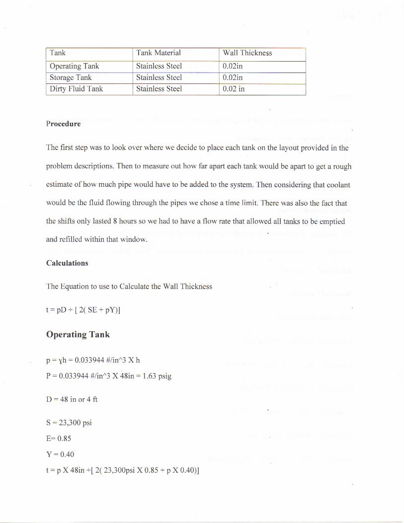
Tank Tank Material Wall Thickness
Operating Tank Stainless Steel 0.02in Storage Tank Stainless Steel 0.02in Dirty Fluid Tank Stainless Steel 0.02 in
Procedure
The first step was to look over where we decide to place each tank on the layout provided in the
problem descriptions. Then to measure out how far apart each tank would be apart to get a rough
estimate of how much pipe would have to be added to the system. Then considering that coolant
would be the fluid flowing through the pipes we chose a time limit. There was also the fact that
the shifts only lasted 8 hours so we had to have a flow rate that allowed all tanks to be emptied
and refilled within that window.
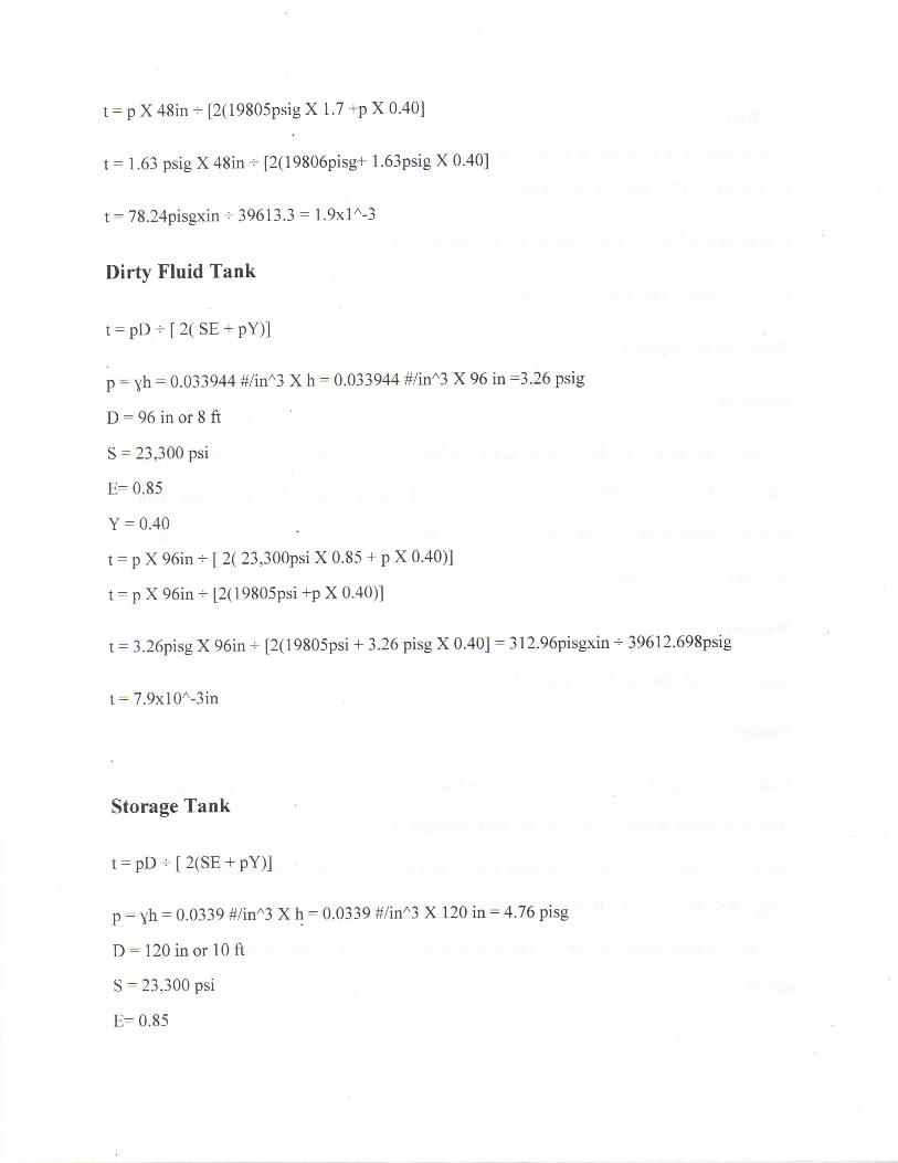
Calculations
The Equation to use to Calculate the Wall Thickness
t = pD - [ 2( SE + pY)]
Operating Tank
p = yh = 0.033944 #/inA3 X h
P = 0.033944 #/inA3 X 48in = 1.63 psig
D = 48 in or 4 ft
S = 23,300 psi
E= 0.85
Y = 0.40
t = p X 48in - [ 2( 23,300psi X 0.85 + p X 0.40)]
t = p X 48in - [2(19805psig X 1.7 +p X 0.40]
t = 1.63 psig X 48in - [2(19806pisg+ 1.63psig X 0.40]
t = 78.24pisgxin- 39613.3 = 1.9xlA-3
Dirty Fluid Tank
t = pD + [ 2( SE + P Y ) ]
p = yh = 0.033944 #/inA3 X h = 0.033944 #/inA3 X 96 in =3.26 psig
D = 96 in or 8 ft
S = 23,300 psi
E=0.85
Y = 0.40
t = p X 96in + [ 2( 23,300psi X 0.85 + p X 0.40)]
t = p X 96in -s- [2(19805psi +p X 0.40)]
t = 3.26pisg X 96in + [2(19805psi + 3.26 pisg X 0.40] = 312.96pisgxin •*• 39612.698psig
t = 7.9xlOA-3in
Storage Tank
t = pD + [ 2(SE + pY)]
p = yh = 0.0339 #/inA3 X h = 0.0339 #/inA3 X 120 in = 4.76 pisg
D = 120 in or 10 ft
S = 23,300 psi
E= 0.85

Y = 0.40
t = p X 96in - [ 2( 23,300psi X 0.85 + p X 0.40)]
t = p X 96in - [2( 19805psi +p X 0.40]
t= 4.76 pisg X 120 in * [ 2(19805psi + 4.76 pisg X 0.40]
t=571.2pisg.in + 39613.8pisg = 0.014in
Drawings & Diagrams
Summary
To calculated the wall thickness of the tanks you have consider pressure, dimensions and use
references for the allowable tension, longitudinal joint quality factor and the correction factor.
With this information, you can determine the wall thickness which will have a major impact on
the longevity of your tank.
Materials
Operating Tank, Storage Tank, Dirty Fluid Tank
Analysis
Tanks do not require thick walls like homes in buildings because steel is a very strong and
durable material. When determining the wall thickness is it important not to waste material or
space in the tank for the fluid being held. That is way wall thickness is very small. We will be
using a wall thickness of 0.02in for our project instead of the wall thickness calculated. That's
why we will have uniformity and all the tanks will have the required thickness to remain in
service.

Team 7 Continental AG proposal
Task 3
Purpose: To calculate the required thickness of the 24 in. nominal diameter blind flange for the physical access port to the 7,500 gal. dirty coolant holding tank.
24 inch NPS 1 1/4 in x 20
26 inches
Diagrams:
Sources: Mott, R. Untener, J.A., "Applied Fluid Mechanics", 7 t h ed. Pearson Education, Inc, (2015).
Academia.edu, https://www.academia.edu/6520039/Blind Flange Thickness calculation .
Standard of New England, LLC, "Number and Size of bolts for flanged joints - ASME B16.5", http://www.standardne.com/STD%20NE%20BOLT%20CHART.pdf
Design Considerations:
• Incompressible fluids • Constant properties • Temperature range from -20 F — 105 F • Inner Diameter measurements, Dg, from appropriate inner diameter of schedule 40, 24 in NPS. • Academia.edu resource references ASME-B-31.3, from the clause 304.5.3. I believe these are
boiler code calculations. General enough for my purposes, but due to such low pressures this system is working with, required thickness is expected to be low.
• I will assume a quality factor, E, and weld joint strength, W, to be one. The materials for this project will be of the highest quality.
• Sum of allowances variable, C, will be taken as 3 mm for corrosion allowances. • Design pressure, P, and stress value of material need not be completely converted to SI units, as
these terms' units cancel in the equation to be used, thus the ratio remains the same. • Material: ASTM A 105 - low carbon steel for piping applications. • The referenced table from Standard of New England, LLC denotes use of (20) 1 % in. diameter
bolts as standard for this blind.
tm= + C
1 6 S E W
[Equation]:
Team 7 Continental AG proposal
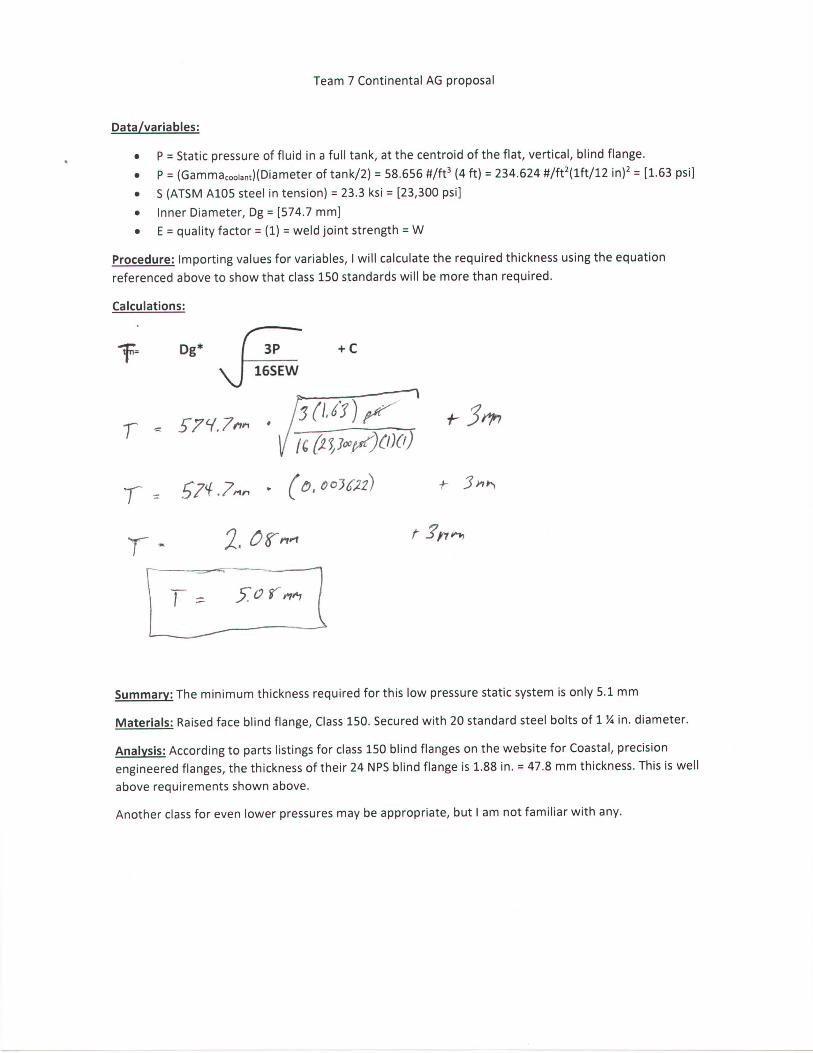
Data/variables:
• P = Static pressure of fluid in a full tank, at the centroid of the flat, vertical, blind flange. • P = (GammaCooiant)(Diameter of tank/2) = 58.656 #/ft3 (4 ft) = 234.624 #/ft 2(lft/12 in) 2 = [1.63 psi] • S (ATSM A105 steel in tension) = 23.3 ksi = [23,300 psi] • Inner Diameter, Dg = [574.7 mm] • E = quality factor = (1) = weld joint strength = W
Procedure: Importing values for variables, I will calculate the required thickness using the equation referenced above to show that class 150 standards will be more than required.
Calculations:
Summary: The minimum thickness required for this low pressure static system is only 5.1 mm
Materials: Raised face blind flange, Class 150. Secured with 20 standard steel bolts of 1 % in. diameter.
Analysis: According to parts listings for class 150 blind flanges on the website for Coastal, precision engineered flanges, the thickness of their 24 NPS blind flange is 1.88 in. = 47.8 mm thickness. This is well above requirements shown above.
Another class for even lower pressures may be appropriate, but I am not familiar with any.
t)l\ U5
NOTES:
. THE LEFT WALL OF THE BUILDING IS SO FT FROM THE RAILROAD TRACKS
• THE BOTTOM WALL OF THE BUILDING IS 200 FT FROM THE HIGHWAY
15000 GAL STORAGE TANK • •
IS FT 1000 GAL OPERATING TANK
T
50C FT
7500 GAL DIRTY FLUID TANK
DRAWN Nate CHECKED
2/9/2017
QA
MFC lank Qwjtfnh. SEE [ IDWGNO 1 REV
D [ |Tank Locations Building Plajns
APPROVED lank Qwjtfnh.
SEE [ IDWGNO 1 REV
D [ |Tank Locations Building Plajns l/60o| [SHEET 1 OFl
Group Project
Task 4
Purpose
To determine the time required to fill and empty each tank in the system while considering how many
gallons of fluid the tank would have to hold. Once the time limit is chosen we use that number to
calculate the desired flow rate to fill and empty all tanks.
Sources
Applied Fluid Mechanics 7 t h edition by Robert L . Mott and Joseph A. Untener
Design Considerations
We must take make sure the time it takes to empty and fill all the takes falls within the 8-hour window of
the workers have to complete the job. The sizes of the three tanks must be reviewed as well as the length
of the pipe which can have a major impact on the flow rate.
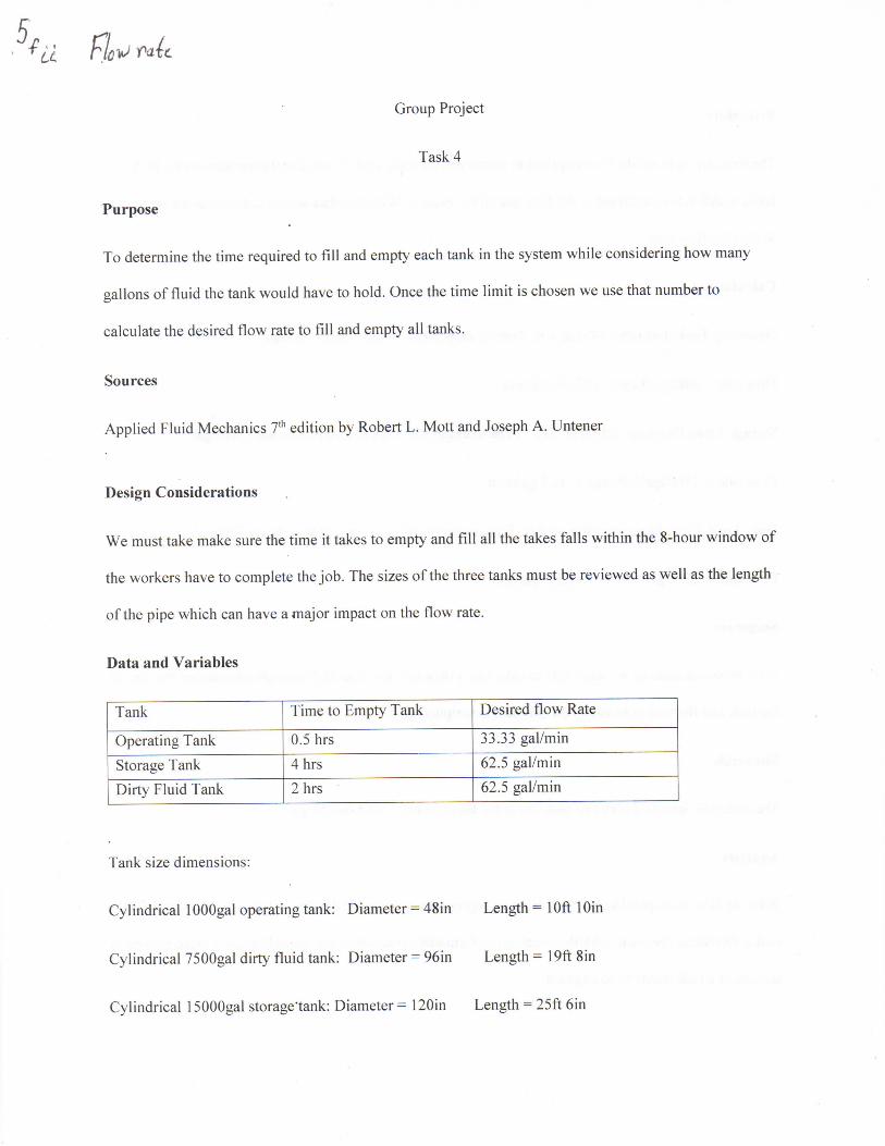
Data and Variables
Tank Time to Empty Tank Desired flow Rate
Operating Tank 0.5 hrs 33.33 gal/min Storage Tank 4 hrs 62.5 gal/min
Dirty Fluid Tank 2 hrs 62.5 gal/min
Tank size dimensions:
Cylindrical 1 OOOgal operating tank: Diameter = 48in Length = 1 Oft 1 Oin
Cylindrical 7500gal dirty fluid tank: Diameter = 96in Length = 19ft 8in
Cylindrical 15000gal storage'tank: Diameter = 120in Length = 25ft 6in
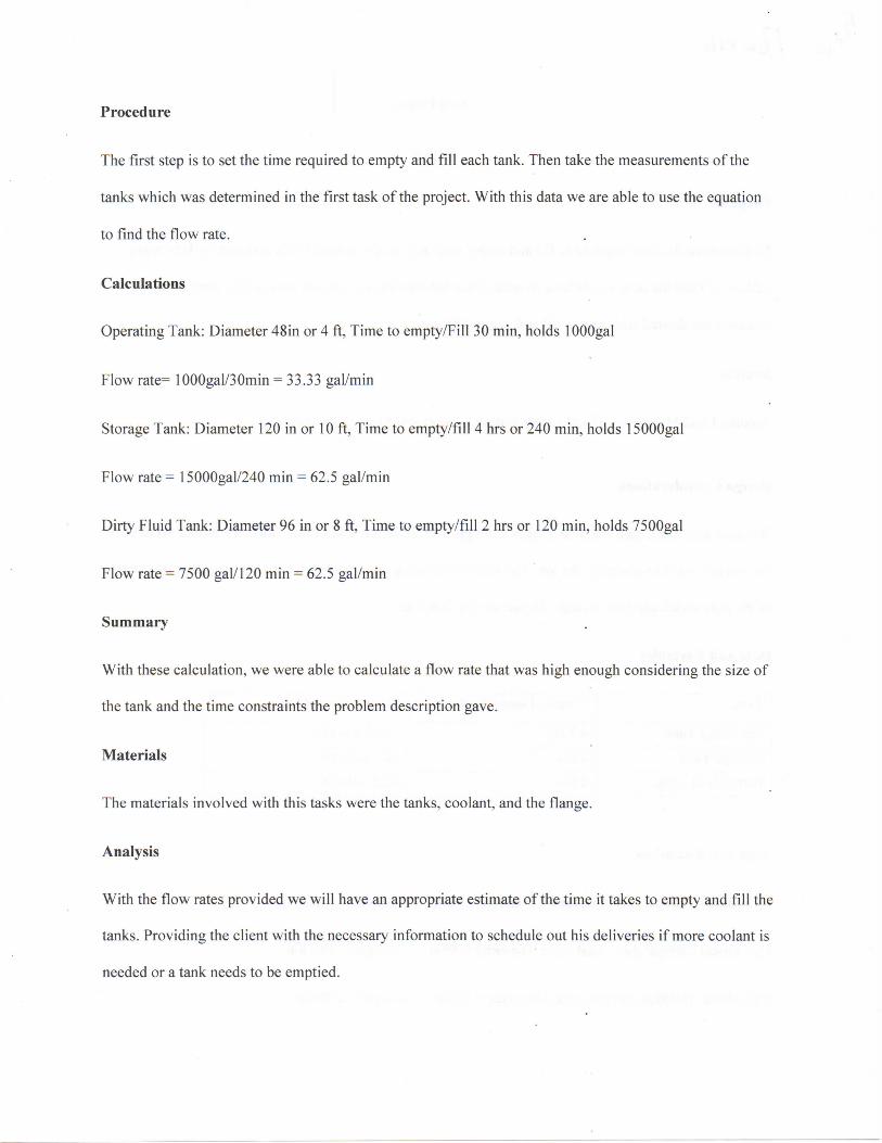
Procedure
The first step is to set the time required to empty and fill each tank. Then take the measurements of the
tanks which was determined in the first task of the project. With this data we are able to use the equation
to find the flow rate.
Calculations
Operating Tank: Diameter 48in or 4 ft, Time to empty/Fill 30 min, holds lOOOgal
Flow rate= 1000gal/30min = 33.33 gal/min
Storage Tank: Diameter 120 in or 10 ft, Time to empty/fill 4 hrs or 240 min, holds 15000gal
Flow rate = 15000gal/240 min = 62.5 gal/min
Dirty Fluid Tank: Diameter 96 in or 8 ft, Time to empty/fill 2 hrs or 120 min, holds 7500gal
Flow rate = 7500 gal/120 min = 62.5 gal/min
Summary
With these calculation, we were able to calculate a flow rate that was high enough considering the size of
the tank and the time constraints the problem description gave.
Materials
The materials involved with this tasks were the tanks, coolant, and the flange.
Analysis
With the flow rates provided we will have an appropriate estimate of the time it takes to empty and fill the
tanks. Providing the client with the necessary information to schedule out his deliveries if more coolant is
needed or a tank needs to be emptied.

Vtpt
Task 5
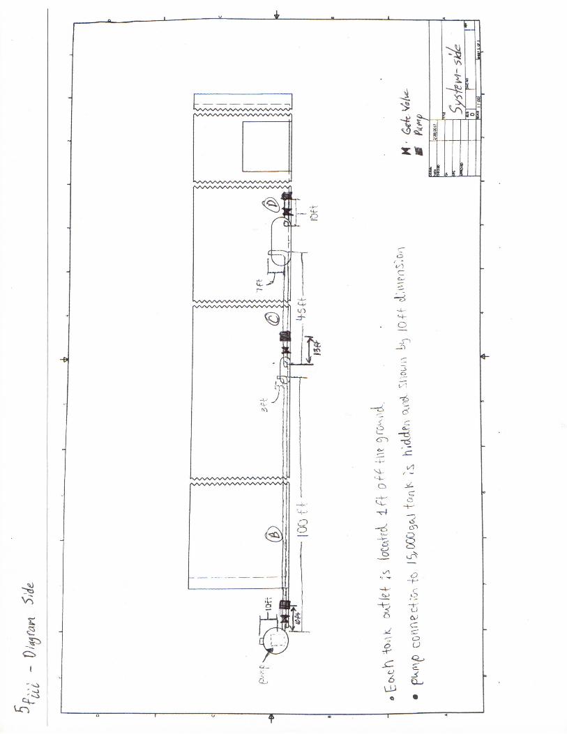
Purpose: To determine the pipe layout and sizes.
Diagrams: See following pipe layout views, overhead and side.
Sources: Mott, R. Untener, J.A., "Applied Fluid Mechanics", 7 t h ed. Pearson Education, Inc, (2015).
Design Considerations: We thought we should run most of the piping along the side of the building in the thought of attaching the supports needed to the wall.
We assumed the inlets to each tank were at the tops of each tank and the outlets located on the back sides towards the ground.
From class, we noticed a trend in the use of schedule 40 steel pipes so we decided to go with what we have seen work the most.
Data/variables: Volumetric flow-rate (Q-high) = 62.5 gal/min = 0.1392 ftA3/s
Volumetric flow rate (Q-low) = 33.3 gal/min = 0.0743 ftA3/s
Critical velocity = 3 m/s = 9.843 ft/s
Procedure: Using the critical velocity we can solve for the approximate required flow area, comparing it to Appendix F (properties of schedule 40 steel pipe).
Calculations: Area (high rate) = Q-high/critical velocity = 0.01414 => 1.5" pipe.
Area (low rate) = Q-low/critical velocity = 0.007545 => 1.25" pipe.
Summary: The beginning section of pipe going into the storage tank and the ending section of pipe going out of the dirty fluid tank we decided to make with a 1V2 in diameter. Every other section of the system, from the outlet of the storage tank to the inlet of the dirty fluid tank, we decided to make 1 % in diameter.
Materials: 30 ft - 1.5" sch. 40 steel pipe, 208 ft - 1.25" sch 40 steel pipe.
Analysis: In total, we will need 238 ft of piping to complete our system, along with a 50 ft length of smooth plastic flexible engaging lock hose to attach to the train and reclamation truck.

Group Project
Task 6
Purpose
To provide information on the number of valves, elbows and fitting that will be in our pipe system as well
as the type of valve, material and size it will be. This is not a system driven by gravity so it will not be a
pumped system.
Drawings and Diagrams
See following pipe and valve layout, overhead and side views
Sources
Applied Fluid Mechanics 7 t h edition by Robert L . Mott and Joseph A. Untener
Design Considerations
The number of valves and their specific sizes was determined from the calculations and design choses
made in task one through five. We also researched the safety codes and procedures to follow when
choosing the material to use for our system. Al l the elbows in our project will be long radius elbows Data and Variables
Type of Valve Size Material
Connect flanges (x2) 1.5 in Steel
Gate Valves (x2) 1.5 in Brass
90 Degree elbows (x3) 1.5 in Schedule 40 Steel
Gate Valves (x2) 1.25 Brass
90 Degree elbows (x7) 1.25 Schedule 40 Steel
III Pfe-
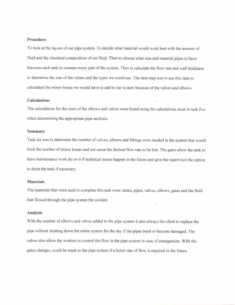
Procedure
To look at the layout of our pipe system. To decide what material would work best with the amount of
fluid and the chemical composition of our fluid. Then to choose what size and material pipes to have
between each tank to connect every part of the system. Then to calculate the flow rate and wall thickness
to determine the size of the values and the types we could use. The next step was to use this data to
calculated the minor losses we would have to add to our system because of the valves and elbows.
Calculations
The calculations for the sizes of the elbows and valves were found using the calculations done in task five
when determining the appropriate pipe sections.
Summary
Task six was to determine the number of valves, elbows and fittings were needed in the system that would
limit the number of minor losses and not cause the desired flow rate to be lost. The gates allow the tank to
have maintenance work do on it if technical issues happen in the future and give the supervisor the option
to drain the tank if necessary.
Materials
The materials that were used to complete this task were: tanks, pipes, valves, elbows, gates and the fluid
that flowed through the pipe system the coolant.
Analysis
With the number of elbows and valves added to the pipe system it also always the client to replace the
pipe without shutting down the entire system for the day if the pipes burst or become damaged. The
valves also allow the workers to control the flow in the pipe system in case of emergencies. With the
gates changes, could be made to the pipe system if a better rate of flow is required in the future.
Hi V Team 7 Continental AG proposal
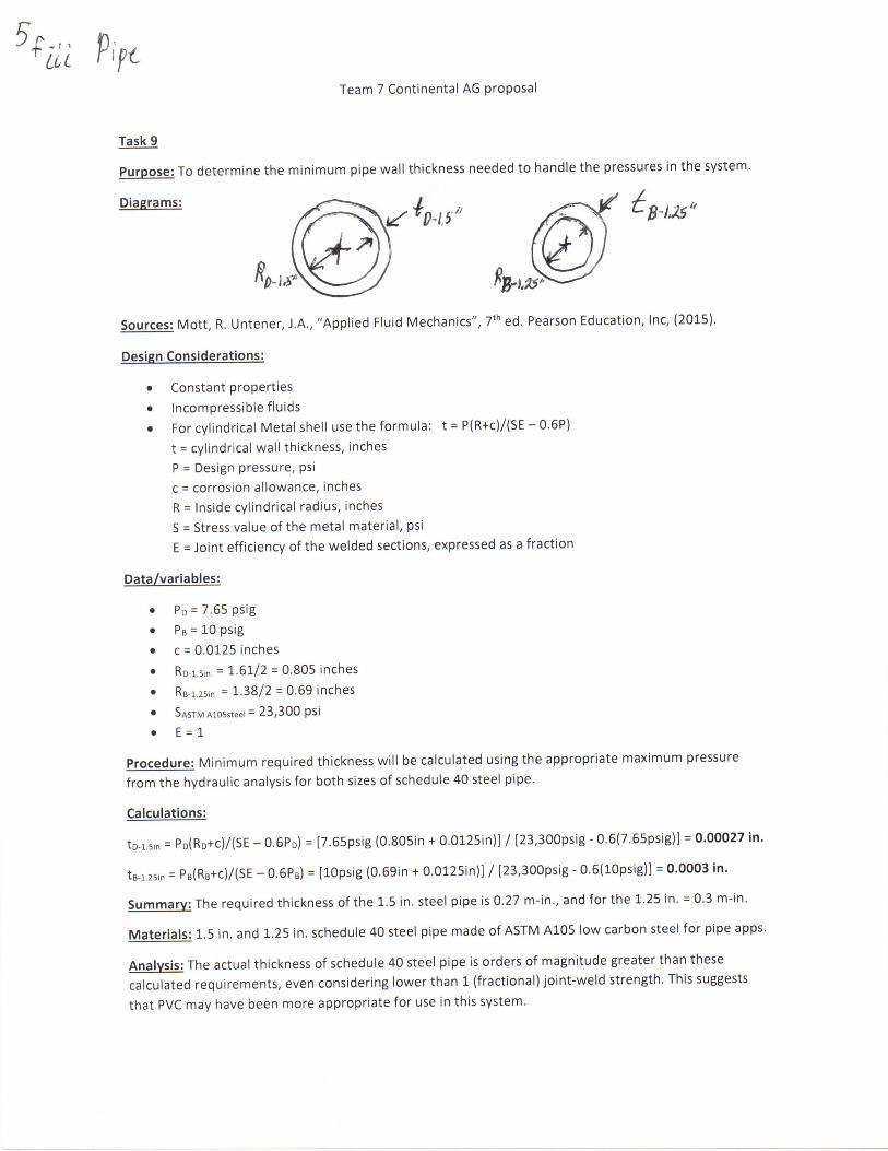
Task 9
Purpose: To determine the minimum pipe wall thickness needed to handle the pressures in the system.
Diagrams:
Sources: Mott, R . Untener, J.A., "Applied Fluid Mechanics", 7 t h ed. Pearson Education, Inc, (2015).
Design Considerations:
• Constant properties
• Incompressible fluids • For cylindrical Metal shell use the formula: t = P(R+c)/(SE - 0.6P)
t = cylindrical wall thickness, inches P = Design pressure, psi c = corrosion allowance, inches R = Inside cylindrical radius, inches S = Stress value of the metal material, psi
E = Joint efficiency of the welded sections, expressed as a fraction
Data/variables:
• P D = 7.65 psig
• PB = 10psig • c = 0.0125 inches • RD-I sin = 1.61/2 = 0.805 inches • RB-i.2Sin = 1.38/2 = 0.69 inches • SASTM A105steel = 23,300 psi • E = 1
Procedure: Minimum required thickness will be calculated using the appropriate maximum pressure from the hydraulic analysis for both sizes of schedule 40 steel pipe.
Calculations:
t D-i.5,n = P D ( R D + C ) / ( S E - 0.6PD) = [7.65psig (0.805in + 0.0125in)] / [23,300psig - 0.6(7.65psig)] = 0.00027 in.
t B - i . 2 5in = P B ( R B + C ) / ( S E - 0.6PB) = [lOpsig (0.69in + 0.0125in)] / [23,300psig - 0.6(10psig)] = 0.0003 in.
Summary: The required thickness of the 1.5 in. steel pipe is 0.27 m-in., and for the 1.25 in. = 0.3 m-in.
Materials: 1.5 in. and 1.25 in. schedule 40 steel pipe made of ASTM A105 low carbon steel for pipe apps.
Analysis: The actual thickness of schedule 40 steel pipe is orders of magnitude greater than these calculated requirements, even considering lower than 1 (fractional) joint-weld strength. This suggests that PVC may have been more appropriate for use in this system.

A.
F 3
n o
% o
C?
\J~1
i n P
R ^ 1
m
9 7*"
o o
"St— ? - 4 -p 3 O ~ *
K —) —)
-o o ~ ; ,5" p
9 -i 1
O
OS"
2
T

V
Team 7 Continental AG proposal
Task 7
Purpose: To develop the hydraulic analysis of all portions of the Team 7 system.
Diagrams: All section diagrams have been flattened into equivalent systems, for ease of view.
Train Car -> Sec. A -> 15,000 gal -> Sec. B -> 1,000 gal -> Sec. C -> 7,500 gal -> Sec. D -> Truck
Section diagrams will appear at the top of appropriate calculations page.
Sources: Mott, R. Untener, J.A., "Applied Fluid Mechanics", 7 t h ed. Pearson Education, Inc, (2015).
Design Considerations:
• Incompressible fluids • Constant properties • Temperature range from-20 F — 105 F • Pipe sizes are fixed, using critical velocity of 9.84 ft/s (3 m/s) • Sections A and D use 1.5 in. schedule 40 steel pipe and fittings, coupled with a 1.5 in. plastic roll-
up quick connect hose for industrial applications. • Sections B and C use 1.25 in. schedule 40 steel pipe and fittings. • This analysis uses only two volumetric flow rates. Sections A,D, using Qhigh and B,C, using Oj o w . • Vhigh and V|0W have been calculate from the appropriate Q value. • Two Reynolds numbers will be computed for the appropriate section, using 5 degrees F. • Since the kinematic viscosity value rises as temperature lowers, the Reynolds number will also
lower. Thus, the most energy losses due to friction will occur at lowest temperature values. • This value will be taken as 5 degrees F since appropriate insulation will prevent the freezing of
coolant at extreme temperature lows. • Inlets to the respective pipe section from tank will be taken as squared edge inlet, K = 0.5
Data/variables:
• Di25= 0.1150 ft • ReHi8h(5F) = Vhigh D L S = (9.84 ft/s)(0.1342 ft) = 4.7 x 10 4
• ReLow(5F) = Vio„ Di.25 = (7.15 ft/s)(0.1150 ft) = 3 x 10 4
Procedure: Using given values and properties of known materials I can obtain relevant f-values from the Moody chart and values of fT for new, clean schedule 40 steel of the appropriate size.
• Computing all energy losses within each section is a straightforward calculation. • Using Bernoulli's equation to solve for the energy contributed to the fluid by the pump, h A . • Using a point at the outlet for the relevant section's pump, I will use Bernoulli's equation again
to determine the maximum pressure in the line for each section.
Qh,gh =62.5 gal/min Ojow =33.3 gal/min Di.5 = 0.1342 ft
0.1392 ft 3/s 0.0743 ft3/s

Team 7 Continental AG proposal
Sec hon A
- ~ IRl
is'u&^tfe Y :
r 5 f f
Otit* fife' 1.5" *A HO $4e* (
Calculations, section A: Car lioll^a hnlc. /\/\^ <ru\
J i ^ L - cj?!L ' - <t sop* k , - K¥ = OS(1.5*35fi) = 0 . * < t ~7Z7
5?
/, r \6ois.4H- & o< #
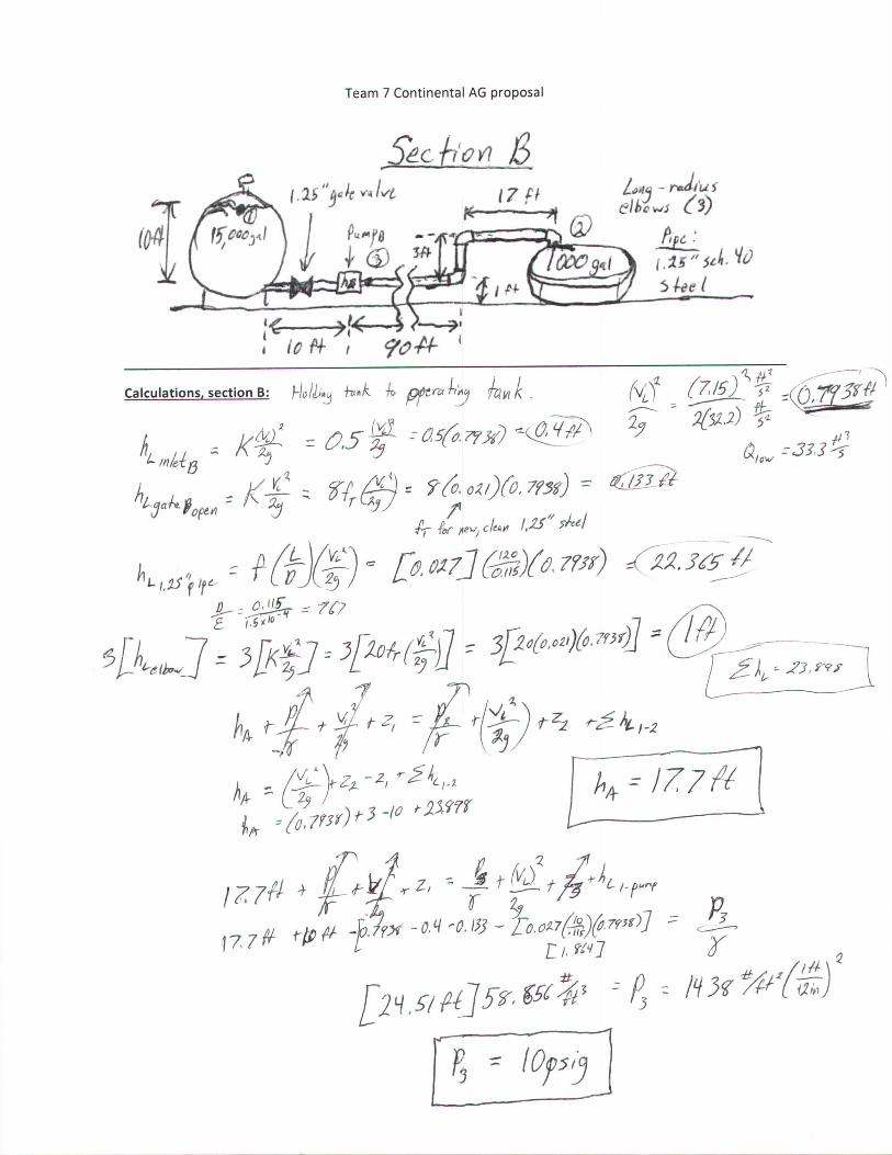
Team 7 Continental AG proposal
" j ^ r m/vfc ^ 7 ^ Lm -rmdhii
l>pc •'
Calculations, section B: f-/o//̂ T^H/C 71* ^£r# «L ^ £ ^775J - 5 ? CO^f^Jl
, 7 7 # W -fir* - o M % ~ ro.^sx^J * <JL
r , - 10f si J
Team 7 Continental AG proposal
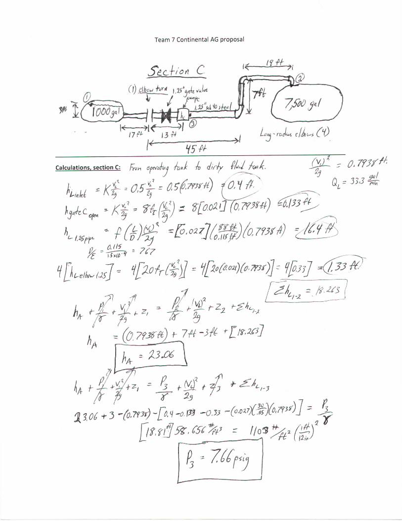
Sech'on C
k — n < — M ®
H5&
Calculations, section C: foh Ofenkj A, J A dirty f/u.J J ^ L ~ 0> 7?3f^
P3 5 *7J£f<y
Team 7 Continental AG proposal
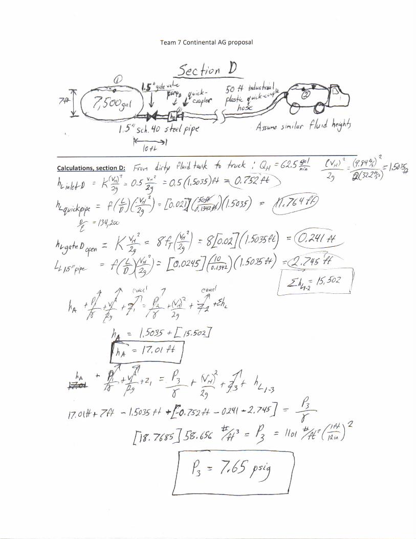
1.5" StL Ho 5 he I f>if><
(Cti-
C a l c u l a , i o n , section D: ff,, Uy M U T4 Uck .^-MSg J^ll ,<^lc
faict •J coiled
* 7
7-7 ' ^
P3 - 7'65 psij
Team 7 Continental AG proposal
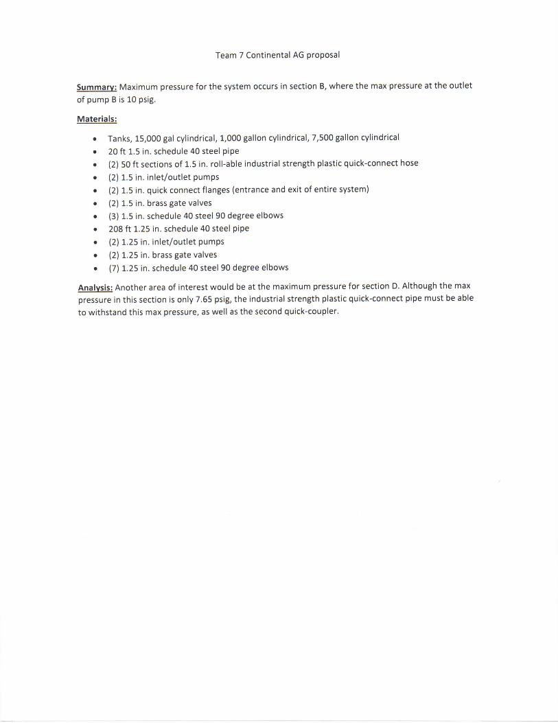
Summary: Maximum pressure for the system occurs in section B, where the max pressure at the outlet of pump B is 10 psig.
Materials:
• Tanks, 15,000 gal cylindrical, 1,000 gallon cylindrical, 7,500 gallon cylindrical • 20 ft 1.5 in. schedule 40 steel pipe • (2) 50 ft sections of 1.5 in. roll-able industrial strength plastic quick-connect hose • (2) 1.5 in. inlet/outlet pumps • (2) 1.5 in. quick connect flanges (entrance and exit of entire system) • (2) 1.5 in. brass gate valves • (3) 1.5 in. schedule 40 steel 90 degree elbows • 208 ft 1.25 in. schedule 40 steel pipe • (2) 1.25 in. inlet/outlet pumps • (2) 1.25 in. brass gate valves • (7) 1.25 in. schedule 40 steel 90 degree elbows
Analysis: Another area of interest would be at the maximum pressure for section D. Although the max pressure in this section is only 7.65 psig, the industrial strength plastic quick-connect pipe must be able to withstand this max pressure, as well as the second quick-coupler.
Team 7 Continental AG proposal
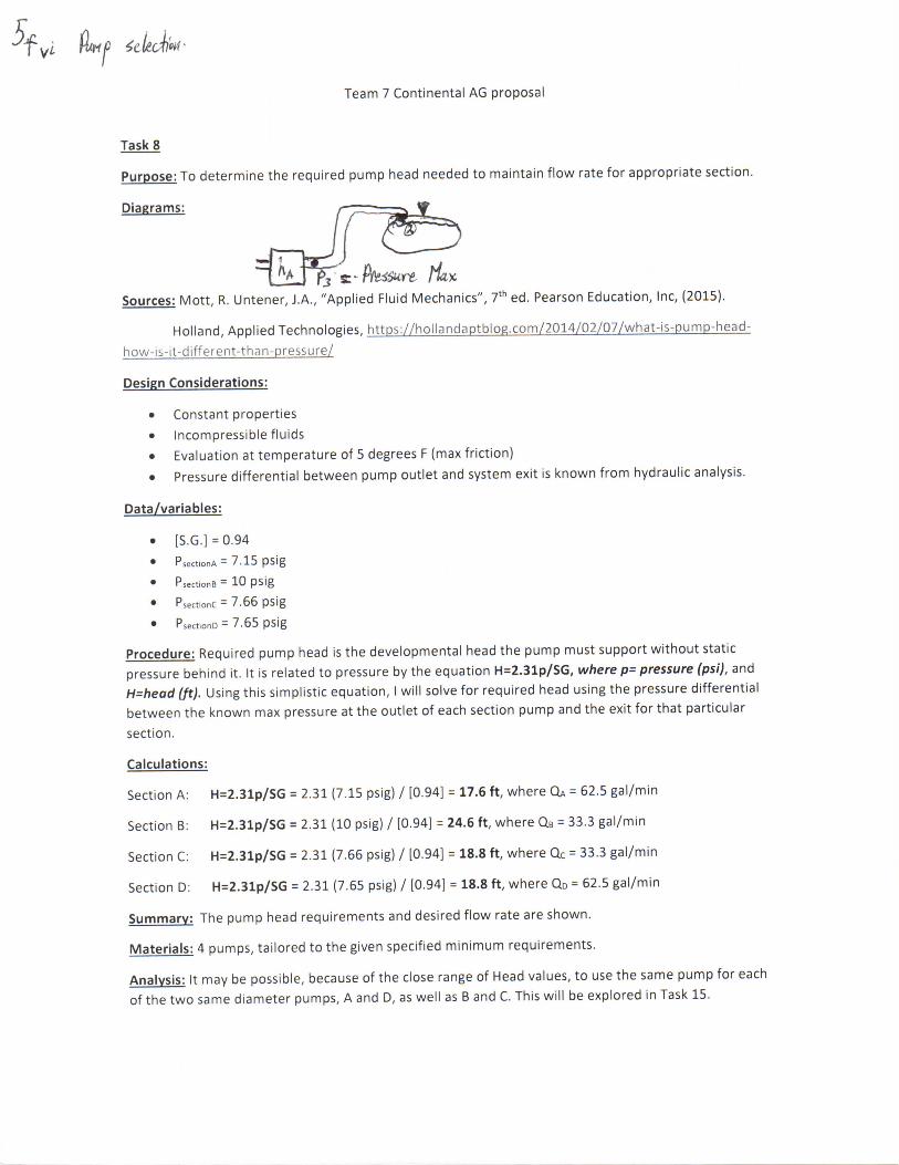
Task 8
Purpose: To determine the required pump head needed to maintain flow rate for appropriate section.
Diagrams: /- — ~ —̂ W
Sources: Mott, R. Untener, J.A., "Applied Fluid Mechanics", 7 t h ed. Pearson Education, Inc, (2015).
Holland, Applied Technologies, https://hollandaptblog.com/2014/02/07/what-is-pump-head-
how-is-it-different-than-pressure/
Design Considerations:
• Constant properties • Incompressible fluids • Evaluation at temperature of 5 degrees F (max friction)
• Pressure differential between pump outlet and system exit is known from hydraulic analysis.
Data/variables:
• [S.G.] = 0.94
• Psect.onA = 7.15 psig • PsectionB = 10 psig • PsectionC = 7.66 psig • PsectlonD = 7.65 p S i g
Procedure: Required pump head is the developmental head the pump must support without static pressure behind it. It is related to pressure by the equation H=2.31p/SG, where p= pressure (psi), and H=head (ft). Using this simplistic equation, I will solve for required head using the pressure differential between the known max pressure at the outlet of each section pump and the exit for that particular section.
Calculations:
Section A: H=2.31p/SG = 2.31 (7.15 psig) / [0.94] = 17.6 ft, where QA = 62.5 gal/min
Section B: H=2.31p/SG = 2.31 (10 psig) / [0.94] = 24.6 ft, where QB = 33.3 gal/min
Section C: H=2.31p/SG = 2.31 (7.66 psig) / [0.94] = 18.8 ft, where QC = 33.3 gal/min
Section D: H=2.31p/SG = 2.31 (7.65 psig) / [0.94] = 18.8 ft, where QD = 62.5 gal/min
Summary: The pump head requirements and desired flow rate are shown.
Materials: 4 pumps, tailored to the given specified minimum requirements.
Analysis: It may be possible, because of the close range of Head values, to use the same pump for each of the two same diameter pumps, A and D, as well as B and C. This will be explored in Task 15.