met-pro lobal pump s d pump seriesph/php · a met-pro fluid handling technologies business ......
TRANSCRIPT

Horizontal Process Pumps
Instruction Manual MC 1.2.35
MET-PROA Met-Pro Fluid Handling Technologies Business
Combining the Resources of Dean Pump, Fybroc & Sethco
Global Pump Solutions
DO NOT INSTALL, OPERATE, OR SERVICE THIS PUMP BEFORE READING THE ENTIRE MANUAL
DEAN PUMP® SERIES PH/PHP

INDEX
Mechanical Design Specifications . . . . . . . . . . . . . . . . . . . . . . . . . . . . . . . . . . . .1Standard Materials of Construction . . . . . . . . . . . . . . . . . . . . . . . . . . . . . . . . . . . .1Allowable Pump Suction Pressure . . . . . . . . . . . . . . . . . . . . . . . . . . . . . . . . . . . . .1Working Pressure vs. Pumping Temperature . . . . . . . . . . . . . . . . . . . . . . . . . . . . . .2Product Inspection and Test . . . . . . . . . . . . . . . . . . . . . . . . . . . . . . . . . . . . . . . . .3Product Warranty . . . . . . . . . . . . . . . . . . . . . . . . . . . . . . . . . . . . . . . . . . . . . . . .3Receiving Pump . . . . . . . . . . . . . . . . . . . . . . . . . . . . . . . . . . . . . . . . . . . . . . . . .3Storage . . . . . . . . . . . . . . . . . . . . . . . . . . . . . . . . . . . . . . . . . . . . . . . . . . . . . . .3Installation . . . . . . . . . . . . . . . . . . . . . . . . . . . . . . . . . . . . . . . . . . . . . . . . . . . . .4
Application and Reapplication . . . . . . . . . . . . . . . . . . . . . . . . . . . . . . . . . . .4Pump Foundation . . . . . . . . . . . . . . . . . . . . . . . . . . . . . . . . . . . . . . . . . . . .4Baseplate Mounting and Alignment . . . . . . . . . . . . . . . . . . . . . . . . . . . . . . .4Suction and Discharge Piping . . . . . . . . . . . . . . . . . . . . . . . . . . . . . . . . . . .5Pump and Driver Alignment . . . . . . . . . . . . . . . . . . . . . . . . . . . . . . . . . . . . .5
Allowable Nozzle Loads . . . . . . . . . . . . . . . . . . . . . . . . . . . . . . . . . . . . . . . . . . .6Instructions for Use of Allowable Loads . . . . . . . . . . . . . . . . . . . . . . . . . . . . .7
Pump Cooling Requirements . . . . . . . . . . . . . . . . . . . . . . . . . . . . . . . . . . . . . . . .10Seal Chamber Cooling . . . . . . . . . . . . . . . . . . . . . . . . . . . . . . . . . . . . . . .10Mechanical Seal Gland Cooling . . . . . . . . . . . . . . . . . . . . . . . . . . . . . . . .10Bearing Housing Cooling . . . . . . . . . . . . . . . . . . . . . . . . . . . . . . . . . . . . .10Cooling Water Piping . . . . . . . . . . . . . . . . . . . . . . . . . . . . . . . . . . . . . . . .10Cooling Water Flow Rates . . . . . . . . . . . . . . . . . . . . . . . . . . . . . . . . . . . . .10
Pump Heating Requirements . . . . . . . . . . . . . . . . . . . . . . . . . . . . . . . . . . . . . . . .11Pump Lubrication . . . . . . . . . . . . . . . . . . . . . . . . . . . . . . . . . . . . . . . . . . . . . . .11Starting the Pump . . . . . . . . . . . . . . . . . . . . . . . . . . . . . . . . . . . . . . . . . . . . . . .11Pump Start Up Check List . . . . . . . . . . . . . . . . . . . . . . . . . . . . . . . . . . . . . . . . . .12Spare Parts . . . . . . . . . . . . . . . . . . . . . . . . . . . . . . . . . . . . . . . . . . . . . . . . . . .12
Ordering Spare Parts . . . . . . . . . . . . . . . . . . . . . . . . . . . . . . . . . . . . . . . .12Pump Designation Code for pH2110 . . . . . . . . . . . . . . . . . . . . . . . . . . . . . . . . .13
pH2110 Pump Section View . . . . . . . . . . . . . . . . . . . . . . . . . . . . . . . . . . .13pH2110 Parts List . . . . . . . . . . . . . . . . . . . . . . . . . . . . . . . . . . . . . . . . . . .13
Pump Designation Code for pH2140 . . . . . . . . . . . . . . . . . . . . . . . . . . . . . . . . .14pH2140 Pump Sectional View . . . . . . . . . . . . . . . . . . . . . . . . . . . . . . . . . .14pH2140 Parts List . . . . . . . . . . . . . . . . . . . . . . . . . . . . . . . . . . . . . . . . . . .14
Pump Designation Code for pH2170/pH3170 . . . . . . . . . . . . . . . . . . . . . . . . . .15pH2170/pH3170 Pump Sectional Views . . . . . . . . . . . . . . . . . . . . . . . . . .15pH2170/pH3170 Parts Lists . . . . . . . . . . . . . . . . . . . . . . . . . . . . . . . . . . .15
Pump Designation Code for pH2180 . . . . . . . . . . . . . . . . . . . . . . . . . . . . . . . . .16pH2180 Pump Sectional View . . . . . . . . . . . . . . . . . . . . . . . . . . . . . . . . . .16pH2180 Parts List . . . . . . . . . . . . . . . . . . . . . . . . . . . . . . . . . . . . . . . . . . .16
Disassembly and Assembly Procedures . . . . . . . . . . . . . . . . . . . . . . . . . . . . . . . .17Installation and Maintenance of Seal Chamber Packing . . . . . . . . . . . . . . . . . . . .23
Purpose of Lantern Ring . . . . . . . . . . . . . . . . . . . . . . . . . . . . . . . . . . . . . . .23Internal Seal Connection to the Lantern Ring . . . . . . . . . . . . . . . . . . . . . . . .23External Seal Connection to the Lantern Ring . . . . . . . . . . . . . . . . . . . . . . . .23Lantern Ring Not Used . . . . . . . . . . . . . . . . . . . . . . . . . . . . . . . . . . . . . . .23Packing Installation . . . . . . . . . . . . . . . . . . . . . . . . . . . . . . . . . . . . . . . . . .23Usual Causes of Packing Failure and
Excessive Seal Chamber Leakage . . . . . . . . . . . . . . . . . . . . . . . . . . . . . . .24Installation of Standard Mechanical Seals . . . . . . . . . . . . . . . . . . . . . . . . . . . . . .24
Single Inside Seals . . . . . . . . . . . . . . . . . . . . . . . . . . . . . . . . . . . . . . . . . .24Single Outside Unbalanced Seals . . . . . . . . . . . . . . . . . . . . . . . . . . . . . . . .25Double Inside Unbalanced Seals . . . . . . . . . . . . . . . . . . . . . . . . . . . . . . . .25
Spare Parts . . . . . . . . . . . . . . . . . . . . . . . . . . . . . . . . . . . . . . . . . . . . . . . . . . .26Ordering Spare Parts . . . . . . . . . . . . . . . . . . . . . . . . . . . . . . . . . . . . . . . .26
Installation, Operation and Maintenance pHP Self Priming Pumps . . . . . . . . . . . . .26Installation . . . . . . . . . . . . . . . . . . . . . . . . . . . . . . . . . . . . . . . . . . . . . . . .26Operation . . . . . . . . . . . . . . . . . . . . . . . . . . . . . . . . . . . . . . . . . . . . . . . .26Maintenance . . . . . . . . . . . . . . . . . . . . . . . . . . . . . . . . . . . . . . . . . . . . . .26pHP2110/pHP2140 Pump Sectional Views . . . . . . . . . . . . . . . . . . . . . . . .27
Customer’s Plant Maintenance Record . . . . . . . . . . . . . . . . . . . . . . . . . . . . . . . . .27

1
SERIES PHHORIZONTAL PROCESS PUMPS
pH2110 Series: Types pH2111, 2112, 2114, 2116, 2117, 2118 • pH2140 Series: Types pH2141, 2142, 2144, 2146, 2147, 2148pH2170 Series: Types pH2171, 2172, 2174, 2176, 2177, 2178 • pH3170 Series: Types pH3171, 3172, 3174, 3176, 3177, 3178pH2180 Series: Types pH2181, 2182, 2184, 2186, 2187, 2188
Part No. Part Name Class 22 Class 50 Class 60 CD4MCu Hast. Titanium3 Impeller C.I. (1) 316 (12) Alloy20 (2) CD4MCu Hast. Titanium
5 Casing D.I. (10) 316 (12) Alloy20 (2) CD4MCu Hast. Titanium
5A Casing Drain Plug 1020 Steel 316 S/S Alloy20 316 S/S Hast. Titanium
5C Casing Stud Nut ± Steel (4)
5D Casing Capscrew ≠s‡ Steel (11)Casing Stud ± Steel (6)
7 Cradle Spacer ¨6‡ D.I. (13)
7G Spacer to Brg. Hsg. Capscr. ¨=6‡ 1020 Steel
9 Bearing Housing Foot ¨ C.I. (1)
10 Shaft Sleeve s=6‡ 316 S/S Alloy 20 316 S/S Hast. Titanium
10K Sleeve Key s=6‡ 304 S/S
13 Seal Chamber Gland 316 S/S Alloy 20 316 S/S Hast. Titanium
14 Gland Stud 304 S/S Alloy 20 304 S/S Hast. Titanium
15 Gland Nut 304 S/S Alloy 20 304 S/S Hast. Titanium17 Lantern Ring ≤s= Teflon n
Lantern Ring Ø6‡ C.I. (1) 316 S/S Alloy 2022 Casing Back Cover 6‡ D.I. (10) 316 (12) Alloy 20 (2) CD4MCu Hast. Titanium
22A Back Cover to Cradle Capscrew s=6‡ 1020 Steel
25 Radial Bearing s=6‡ — — — — — —
25A Thrust Bearing s=6‡ — — — — — —
26 Bearing Housing =6‡ D.I. (13) for pH2110 & pHP2110, C.I. (1) for all others
27 Seal Ring ¨=6‡ C.I. (1)
28 Bearing End Cover s=6‡ C.I. (1)
28A Bearing End Cover Capscrew s=6‡ 1020 Steel
28B End Cover Adjusting Screw s=6‡ 1020 Steel
28C Adjusting Screw Locking Nut s=6‡ 1020 Steel
29 Pump Shaft s=6‡ Steel (5)
31 Thrust Bearing Lock Nut ¨=6‡ 1020 Steel
31A Thrust Bearing Lock Washer ¨=6‡ 1020 Steel
56 Casing Foot ∞ C.I. (1)
56A Casing Foot Capscrew ∞= 1020 Steel
56B Casing Foot Dowel ∞= 1020 Steel
75A Tapered Retaining Ring Æs Steel
75B Large Retaining Ring ≤s= Steel
76 Labyrinth Seal – Front s=6‡ Bronze & Viton n
76A Labyrinth Seal – Rear s=6‡ Bronze & Viton n
77 Casing Gasket 6‡ Teflon n
77A Impeller Gasket s=6‡ Teflon n
77B End Cover Gasket s=6‡ Buna (7)
80 Vent s=6‡ —
83 Motor Support (C Face) ≤s= C.I. (1)
95A Mechanical Seal Stationary s=6‡95B Mechanical Seal Rotary s=6‡109 Oil Cooler s=6‡ S/S Tubing with Steel Fins and Steel Fittings
231 Bearing Lock Ring Ø6‡ 1020 Steel
231A Bearing Lock Ring Screw Ø6‡ 1020 Steel
231B Bearing Lock Ring Washer Ø6‡ 1020 Steel
pH2110 pH2140PUMP TYPE pHP2110 pHP2140 pH2170 pH3170 pH2180Direction of Rotation
(Viewed from Coupling End) CW CW CW CW CWHorsepower Rating
@ 3500 rpm 35 HP 100 HP — 200 HP —@ 1750 rpm 15 HP 40 HP 100 HP 100 HP 125 HP@ 1150 rpm 10 HP 30 HP 60 HP — 75 HP
Hydrostatic Test Pressure 430 psig 430 psig 430 psig 565 psig 450 psigCorrosion Allowance 1/8" 1/8" 1/8" 1/8" 1/8"Impeller Balance Single Plane Dynamic BalanceFlanges ANSI Class 150 150 150 300 300Facing – standard F.F. F.F. F.F. F.F. F.F.
– optional R.F. R.F. R.F. R.F. R.F.Finish 125 Ra 125 Ra 125 Ra 125 Ra 125 RaStuffing box jacket pressure maximum 125 psig 125 psig 125 psig 125 psig 125 psigBearing housing cooler pressure maximum 125 psig 125 psig 125 psig 125 psig 125 psigMaximum Suction Pressure 275 psig 275 psig 275 psig 375 psig 300 psigBearings:
Thrust Bearing 5306 5309 7311 BG 7311 BG 5312Radial Bearing 6207 6309 6311 6311 6312Lubrication Oil Oil Oil Oil Oil
Approximate oil capacity of bearing housing 26 oz 42 oz 36 oz 36 oz 64 ozSeal Chamber Dimensions:
Tapered Seal ChamberLength (Depth) 23/8" 31/16" 31/16" 31/16" 45/8"Inside Diameter (Bore) 27/8" 31/2" 37/8" 37/8" 41/4"Shaft Sleeve Diameter 13/8" 13/4" 21/8" 21/8" 21/4"
Cylindrical Seal ChamberLength (Depth) 17/8" 21/4" 23/16" 23/16" 35/16"Inside Diameter (Bore) 27/8" 31/2" 37/8" 37/8" 41/4"Shaft Sleeve Diameter 13/8" 13/4" 21/8" 21/8" 21/4"
Stuffing Box Dimensions:Length (Depth) 21/8" 23/4" 23/4" 23/4" 37/8"Inside Diameter (Bore) 2" 21/2" 27/8" 27/8" 31/4"Shaft Sleeve Diameter 13/8" 13/4" 21/8" 21/8" 21/4"Lantern Gland Width 7/16" 5/8" 5/8" 5/8" 3/4"
Packing Size – Square 5/16" 3/8" 3/8" 3/8" 1/2"Number of Rings with Lantern Ring 5 5 5 5 6Number of Rings without Lantern Ring 6 7 7 7 7Spacing with Lantern Ring 2-G-3 2-G-3 2-G-3 2-G-3 3-G-3Pump Shaft Dimensions:
Span Between Bearings 315/16" 63/8" 515/16" 515/16" 87/16"Span Between Radial Bearing and Impeller 513/16" 77/8" 83/16" 83/16" 103/4"Diameter Under the Sleeve 11/8" 11/2" 17/8" 17/8" 2"Diameter with No Sleeve 13/8" 13/4" 21/8" 21/8" 21/4"Diameter at Coupling 7/8" 11/8" 15/8" 15/8" 15/8"Diameter Between Bearings 11/2" 21/8" 25/8" 25/8" 23/4"Diameter at Impeller 3/4" 11/4" 11/4" 11/4" 15/8"
L3/D4 RatioSleeved Shaft 123 96 44 44 78Solid Shaft (No Sleeve) 55 52 27 27 48
STANDARD MATERIALS OF CONSTRUCTION
¨ pH2140, pH2170, pH3170, pH2180 and pHP2140 only≠ pH2110, pH2140, pH2170, pH2180, pHP2110 and pHP2140 onlyÆ pH2110, and pHP2110 onlyØ pH2170, pH3170, and pH2180 only∞ pH2140 and pHP2140 only± pH3170 only≤ pH2110, pH2140, pHP2110, and pHP2140 onlys Denoted parts are interchangeable in all pH2110 and pHP2110 pumps= Denoted parts are interchangeable in all pH2140 and pHP2140 pumps6 Denoted parts are interchangeable in all pH2170 and pH3170 pumps‡ Denoted parts are interchangeable in all pH2180 pumpsn Registered Trademark of the E.I. DuPont Company
MATERIAL SPECIFICATIONS (REFER TO NUMBERS IN PARENTHESES)
(1) Cast Iron (8) Fibre Sheet — Non-Asbestos Fibre(2) Alloy 20 S/S: ASTM #A744, Grade CN-7M (9) Manila Paper(3) Cast Steel: ASTM #A216, Grade WCB (10) Ductile Iron: ASTM A395(4) Steel: ASTM #A194, Grade 2 (11) Steel: ASTM #A449(5) Alloy Steel: 125,000 TS, 100,000 YP (12) 316 S/S: ASTM #A744 Grade CF-8M(6) Steel: ASTM #A193, Grade B7 (13) Ductile Iron: ASTM A536(7) Buna “N” Rubber
STANDARD, HORIZONTAL, SINGLE STAGE, END SUCTION, OPEN IMPELLER, CENTRIFUGAL PROCESS PUMPS
PUMP SIZEWith Without
Values of FnBalance Holes Balance Holes
pH/pHP3500 1750 1150 3500 1750 1150 3500 1750 1150RPM RPM RPM RPM RPM RPM RPM RPM RPM
psi psi psi1 x 11/2 x 6 pH2110 maximum allowable 18 4.5 2.011/2 x 3 x 6 suction pressure = 18 4.5 2.02 x 3 x 6 maximum allowable 18 4.5 2.01 x 11/2 x 8 discharge pressure 22 5.5 3.511/2 x 3 x 8/ 11/2 x 11/2 x 8 less developed head 18 4.5 2.01 x 2 x 81/2 pH2140 110 185 200 180 200 205 25.2 6.3 2.711/2 x 3 x 81/2 115 185 200 190 195 205 25.2 6.3 2.72 x 3 x 81/2 115 185 200 190 195 205 25.2 6.3 2.73 x 4 x 81/2 #1 110 180 200 210 200 205 39.0 9.7 4.23 x 4 x 81/2 #2 175 200 230 220 9.7 4.21 x 2 x 10 110 180 200 185 195 205 25.2 6.3 2.711/2 x 3 x 10/ 2 x 2 10 110 180 200 185 195 205 25.2 6.3 2.72 x 3 x 10/ 3 x 3 x 10 110 180 200 190 185 205 25.5 6.3 2.73 x 4 x 10 #1/ 4 x 4 x 10 110 180 200 210 205 210 25.2 6.3 2.73 x 4 x 10 #2 180 200 200 205 9.7 4.211/2 x 3 x 111/2 105 180 180 200 25.2 6.3 2.72 x 3 x 111/2 105 180 180 200 25.2 6.3 2.73 x 4 x 111/2 170 200 190 200 14.0 6.04 x 6 x 111/2 150 180 200 205 14.0 6.011/2 x 3 x 131/2 165 195 185 200 6.3 2.72 x 3 x 131/2 165 195 185 200 6.3 2.73 x 4 131/2/ 4 x 4 131/2 165 195 185 200 6.3 2.74 x 6 x 131/2 pH2170 240 260 240 260 23 10.011/2 x 3 x 131/2 pH3170 300 25.22 x 3 x 131/2 300 25.23 x 4 x 131/2 285 25.24 x 6 x 131/2 pH2180 225 275 275 275 22.0 10.06 x 8 x 131/2 225 275 275 275 15.0 6.7
MAX. ALLOWABLE PUMP SUCTION PRESSURE (psi)WITH 2 YR. MIN. THRUST BEARING LIFE
MECHANICAL DESIGN SPECIFICATIONS
Seal Chamber Pressure:With Balance Holes: seal chamber pressure = suction pressureWithout Balance Holes: Pumps are normally furnished without balance holes. seal chamber pressure = (suction pressure) + (Fn x sp. gr.)

2
SERIES PHHORIZONTAL PROCESS PUMPS
WORKING PRESSURE/PUMPING TEMPERATURE
PH2110, PH2140, PH2170, PHP2110, PHP2140
MAXIMUM ALLOWABLE WORKING PRESSURE CURVES
PH3170
PH2180

3
HAZARDOUS SITUATIONS MAY OCCUR UNLESS THIS EQUIPMENT IS APPLIED, INSTALLED, OPERATED, AND MAINTAINED BY THOR-OUGHLY QUALIFIED PERSONNEL IN STRICT ACCORDANCE WITH THE INSTRUCTION MANUAL AND ALL APPLICABLE DRAWINGSAND CODES.
PRODUCT INSPECTION AND TESTThe Products of Dean Pump Division are subject to thorough and rig-orous quality control and inspection procedures through out thewhole of the manufacturing process to assure proper operation in fullconformity with established performance stand ards. On completionof inspection, each unit is oiled, sealed against the entrance of dirt,
and tagged with a signed certificate of inspection prior to shipment.Each pump when shipped is ready to perform the service for whichit was designed with minimum maintenance and expense if properlyinstalled and operated in accordance with the instructions furnished.
DEAN PRODUCT WARRANTYWe warrant to the purchaser from us of Dean Pump products andparts of our own manufacture (Dean Products) that the DeanProducts are free under rated use and service from defects in design,material and workmanship for a period of one (1) year from thedate of installation, but not to exceed eighteen (18) months from thedate of shipment by us. This warranty does not cover (I) any loss ordamage resulting from wear, corrosion, abrasion or deteriorationdue to normal use in rated service; (II) replacement of service itemssuch as shaft packings and mechanical seals; (III) products or partsmanufactured by others but furnished by us which, if defective, shallbe repaired or replaced only to the extent of the original manufactur-er’s warranty; (IV) any loss or damage to or defects in any DeanProducts resulting from the misuse or improper storage, installa tion,or operation thereof; or (V) any loss or damages to or defects in anyDean Products resulting from any alteration or modification thereofnot expressly authorized and approved by us in writing. We shallnot be liable, directly or indirectly, under any circumstances for con-
sequential or incidental damages, including, but not limited, to: (I)any loss of business or profits; and (II) labor, material or othercharges, claims, losses or damages incurred or suffered from, in con-nection with or in consequence of the working upon, alteration, orrepair of any defective Dean Products by persons or firms other thanus. Our liability for breach of warranty hereunder is limited solely tothe repair in our factory or the replacement F.O.B. our factory, asthe case may be, or any Dean Products which shall have been deter-mined by us, after notice to us and inspection by us within the war-ranty period, to be so defective when shipped by us.
THIS WARRANTY AND THE LIABILITY SET FORTH HEREIN ARE EXCLUSIVE AND IN LIEU OF ALL OTHER LIABILITIES ANDWARRANTIES, EXPRESSED OR IMPLIED, INCLUDING IMPLIEDWARRANTIES OF MERCHANTABILITY AND FIT NESS FOR PARTIC-ULAR PURPOSE.
WARNING
Read the instruction manual completely before installing, filling, oper-ating, or maintaining this equipment.
Obtain, read and heed the MSDS (Material Safety Data Sheet) forthe fluids being handled before attempting to fill, operate or main-tain this equipment. Obtain instructions from the Safety Engineerresponsible for your facility before performing any work on thepumping equipment and systems.
Proper storage while not in use and proper installation and startupare essential for successful pump operation. Misuse or improper stor-age, installation or operation of pumps may result in serious loss ordamage. Dean Pump Division is not responsi ble for any loss or dam-age resulting from causes beyond its control, and is not liable forcharges for work performed or materials furnished to repair suchloss or damage.
All installation, operation, and maintenance must be done by thor-oughly qualified personnel in strict accordance with this manual andmust comply with all local, state and Federal codes. Only Deanauthorized service parts must be used in the repair of these pumps.
RECEIVING PUMPWhen the pump is received from the transportation company itshould be promptly inspected for damage and such damage noted
on the bill of lading before it is signed. Claims for shipping damagemust be filed against the carrier.
Care should be exercised in unloading and handling the pump.
STORAGEPumps must be properly covered and protected against mois ture,dirt, and physical damage during storage prior to installa tion. If pro-longed storage is anticipated, a heavy protective coating should beapplied to bearings and all exposed machined surfaces. A rust pre-ventative must be used to protect all steel or cast iron parts.Compression packing or mechanical seals should be removed andstored as well as protected separately.
Pumps must also be protected from moisture, dirt, and physical dam-age during and after installation while the system is being complet-ed. Pumps “stored” on their foundations must be com pletely checkedfor proper installation prior to start-up.
Care in storage and installation will preserve the built in quality ofeach Dean Product.
4
INSTALLATIONAlways wear the appropriate protective apparel when working onor around the pumping equipment. Safety glasses with side shields,heavy work gloves (use insulated work gloves when handling hotitems), steel-toed shoes, hard hat, and any other protective gear asneeded for protection. One example of other gear would be breath-ing apparatus when working near toxic materials. Use liftingdevices, manufactured expressly for the purpose of lifting, to movethe pumping machinery. Do not attempt to lift the assembly or itscomponents manually. Use only devices with lifting capabilities inexcess of the weight of the unit being lifted. Inspect straps, chains,hooks, etc. for damage and lifting capability before use. Lift only atthe center of gravity.
Personal injury, death, and/or equipment damage could occur ifgood lifting practices are not used.
APPLICATION AND REAPPLICATIONAt the time of installation, the equipment received should havealready been selected for the service required. You must read thepaperwork for the installation and check the serial number of thepump to assure that you are installing the correct pump into the ser-vice for which it was selected.
Many pumps look identical from the outside but can be made of dif-ferent materials and/or be constructed differently inside. Personalinjury, death, equipment damage, product (pumpage) damage,and/or product loss could occur if the incorrect pump is installed.
Do not transfer an existing pump to any other service conditions untilyou have thoroughly reviewed the pump construction, materials, sizing, sealing, pressure containing capability, head/capacity capa-bility, and temperature capability with respect to the required service. Consult your Dean Pump sales engineer with all the servicerequirements and a full description of the existing pump (includingthe serial number), seal, and sub-systems so that we can assist you ina successful reapplication.
PUMP FOUNDATIONThe pump foundation provides rigid support to the baseplate andmaintains the exact alignment of the pumping unit. Baseplates aredesigned to rigidly support the pump and driver without vibration ordistortion only when they are properly set, leveled, and secured tothe foundation.
The purchaser may elect to mount the pump without grouting thebaseplate. In any case the baseplate must be fully supported by thecustomer’s mounting means to prevent vibration and distortion.NOTE: Refer to MC 1.2.34 FBP when Dean FRP baseplates are used.
BASEPLATE MOUNTING AND ALIGNMENTThe sequence of mounting which must be observed for proper base-plate and pump mounting is:
1) Place baseplate, with pump and driver mounted thereon, on thepump foundation.
2) Use wedges under the baseplate edges, at each foundationbolt, to properly support and level the unit. Check this with aspirit level. Pull down the baseplate mounting bolt nuts tightlyand recheck for level. Correct if necessary.
3) Align the driver to the pump. See “Pump and DriverAlignment’’ on page 5.
4) Grout the baseplate. Do not grout the baseplate to the founda-tion until the pump and driver are correctly aligned. Channeltype baseplates are made with open ends to allow easy grout-ing and do not require grouting holes in the baseplate.Fabricated structural steel baseplates are provided with grout-ing holes. Fill the entire void under the baseplate with grout andfirmly embed the baseplate edges.
5) Connect the suction and discharge piping without forcing thepiping into position. See “Suction and Discharge Piping’’ onpage 5. The pipe flanges must line up with the pump flanges “ freely”.
Install a “new” bolt, of the correct size per ASME/ANSIB16.5 and the correct material per ASME/ANSI B16.5, inevery bolt hole. Tighten all bolts evenly. Use only new uncorroded fasteners.
WARNING:Strain caused by “forcing”, improper flange bolting, and/or misalignment may cause failure of the pumping unit, flanges, pipingand/or fluid (pumpage) release which could cause personal injury,death, and/or damage to this and/or other equipment.
6) Recheck pump and driver alignment to ensure that no distortionof the pump unit has been caused by piping strain. Correct piping if misalignment has occurred and again align pump anddriver.
7) Connect all other (auxiliary) piping necessary for safe and successful operation of the equipment in the specific serviceconditions of the application. See “Pump CoolingRequirements” on page 10.
WARNING:Make sure that all piping is installed into its correct connection.Installation of a pipe into an incorrect location could result in anexplosion and personal injury or death as well as damage to thisand/or other equipment.
Install pressure relief valves in any cavities that could be subjected topressures in excess of the allowable working pressure. Explosion,personal injury, death, and/or damage to this and/or other equip-ment may occur if pressure exceeds allowable.
One example of the above would be the cooling jacket around theseal chamber. If this chamber were full of water and someonewould close both the inlet and outlet valves and then operate thepump at 500 degrees fahrenheit, the vapor pressure of the water,665 PSIG, would far exceed the capacity of the jacket and possiblyother parts. In this example, a relief valve must be installed betweenthe pump and the outlet valve.
8) Recheck the alignment between the driver (motor, turbine, or engine) and pump shafts. Installation of pipingmay have forced the pump out of alignment. If so, correct the
TYPICAL FOUNDATION LAYOUT
5
piping to remove the distorting load, and realign the pumpand driver.
9) The pump and driver alignment must again be checked at theoperating temperature and alignment corrected under the hotcondition.
10) After about two weeks of normal pump operation the pumpand driver alignment should again be checked under the hotcondition. If alignment is still correct, the driver feet may bedoweled to the baseplate. If the alignment has changed,realign the unit and recheck after two weeks. NOTE: Refer toMC 1.2.34 FBP when Dean FRP baseplates are used.
SUCTION AND DISCHARGE PIPINGSuction and discharge nozzle sizes of Dean pumps are selectedfor proper performance of the pumping unit and are not intendedto determine the suction and discharge pipe sizes. Pipe sizes mustbe determined by the user based on the system requirements.
Suction piping should have a minimum friction loss and thusshould be as short and straight as possible with a pipe diameteras large as economically feasible for the flow rate handled.Suction piping should never be smaller in diameter than the suc-tion nozzle size. When the suction piping is larger than the suctionnozzle size an eccentric reducer is required at the suction flangeand must be installed with the taper located on the underside toeliminate air or vapor pockets. The section of piping attached tothe suction flange of the pump should be straight for a length ofeight pipe diameters or more.
Discharge piping may be the same size as, larger, or smaller thanthe discharge nozzle as the system flow may demand.
In new installations or rebuilt systems, dirt, pipe scale, weldingslag, and general construction debris may get into the piping. It isimportant to prevent this material from entering the pump anddamaging pump parts, mechanical seal faces, or seal chamberpacking. Mechanical seal parts are especially subject to damageeven by very small particles. To prevent damage, a strainer or fil-ter installed in the suction line is recommended. Commercially
able to the pump and should be considered at the time the systemis designed.
NOTE: See page 26 for Installation of pHP self-priming pumps.
PUMP AND DRIVER ALIGNMENTProper running life of a pump and driver unit depends on the accu-racy with which the axis of the driver shaft coincides with the axisof the pump shaft when the unit is running. Although pumps anddrivers are check aligned at the factory, this is only to confirm thatthe unit can be aligned in the field and handling during shipmentand installation will cause the alignment to change.The pump anddriver alignment must always be checked and corrected before thebaseplate is grouted to the foundation and again before the pumpis first started. If the baseplate mounting instructions have beencarefully fol lowed, no difficulties in making the alignment shouldbe experi enced. Failure to properly align the unit will result invibra tion, short bearing life, and reduced mechanical seal or shaftpacking life.
Pumps are not constructed to be used as pipe anchors. Both suc-tion and discharge piping must be supported independently of thepumping unit and thermal expansion joints provided to guardagainst expansion loads on the pump. Pipes should be anchoredbetween the expansion joint and the pump and as closely to thepump as possible. Failure to provide proper piping support andexpansion joints may impose strains on the pump ing unit whichwill result in serious misalignment. Any and all loads upon thepump must be with-in the maximum allowable values given in thesection titled “Allowable Nozzle Loads” on page 6.
No allowance for thermal expansion is made for motor drivenunits in mounting the driver. Allowance for turbine mountingshould be in accordance with the turbine manufacturer’s recom-mendations. Final alignment must always be checked and correct-ed at the operating temperatures of the pump and driver.
Misalignment of the two shafts is of two kinds. The first of these isangular misalignment where the axis of one shaft is at an anglefrom the other. The other is offset alignment where the center ofone shaft is offset from the center of the other shaft. These effectsusually occur together so that both angular and offset misalignmentare present.
Coincident alignment of the driver and pump shaft is measured atthe faces of the coupling hubs. Because of the variety of couplingtypes furnished at customer’s request, the procedure here given isgeneral in nature but may be applied by simple adaption to mostcoupling types.
The first step is to remove the spacer from the coupling. To one ofthe remaining coupling hubs, firmly seated on the shaft, attach adial indicator. Let the indicator button ride on the face of the othercoupling hub and near the outside diameter. Rotate the shaft onwhich the dial indicator is mounted, allowing the indicator buttonto move on the stationary coupling hub. The indicator dial move-ment will show the difference in distance between the two hubs.This indicates the amount of angular misalignment between thehubs and therefore the shaft axes. Good practice suggests align-ment to within 0.002" T.l.R.
available strainers or filters as recommended by their manufactur-ers can do an excellent job. In addition, special filtering andmechanical seal flushing may be required. Consult your Dean rep-resentative. Suction line screens or strainers may usually beremoved when, after several days of use, no dirt has been collect-ed and the system is clean.
Remember that screens and filters in the suction line are restrictivedevices which reduce the net positive suction head (NPSH) avail-
TYPICAL PUMP PIPING
6
To check the offset alignment, mount the dial indicator as aboveexcept with the indicator button on an outside diameter of the sta-tionary coupling hub. Rotate the shaft on which the dial indicatoris mounted, allowing the indicator button to ride on the outsidediameter of the stationary hub. The indicator dial move ment willshow the difference in the center locations of the two shafts. Goodpractice suggests alignment to within 0.002" T.I.R.
Angular and offset alignment is adjusted by placing thin metalshims under the driver mounting feet to bring the drive intoexact alignment with the bolted down pump. If misalignment isof major proportions, the baseplate has been improperly installedon the foundation and must be releveled before proceeding withalignment.
After each change, it is necessary to recheck both angular andoffset alignment of the coupling. After driver is aligned to thepump, tighten all hold-down bolts and then recheck alignment.
Allowable error of shaft alignment is somewhat dependent onthe coupling type. However, the closer the running alignment,the better the running life will be.
INDICATOR SETUP TO READ OFFSET MISALIGNMENTINDICATOR SETUP TO READ ANGULAR MISALIGNMENT
ALLOWABLE NOZZLE LOADSThe allowable loads given below and the procedure for application are as specified by the “American National Standard for Centrifugaland Vertical Pumps for Allowable Nozzle Loads”, ANSI/HI 9.6.2-2001. For additional information and application, including examples,refer to this standard.
SYMBOLSFxs = applied force on x-axis on suction nozzleFys = applied force on y-axis on suction nozzleFzs = applied force on z-axis on suction nozzle
Mxs = applied moment about x-axis on suction nozzleMys = applied moment about y-axis on suction nozzleMzs = applied moment about z-axis on suction nozzle
Fxd = applied force on x-axis on discharge nozzleFyd = applied force on y-axis on discharge nozzleFzd = applied force on z-axis on discharge nozzle
Mxd = applied moment about x-axis on discharge nozzleMyd = applied moment about y-axis on discharge nozzleMzd = applied moment about z-axis on discharge nozzle
Fxs max = allowable force on x-axis on suction nozzleFys max = allowable force on y-axis on suction nozzleFzs max = allowable force on z-axis on suction nozzle
Mxs max = allowable moment about x-axis on suction nozzleMys max = allowable moment about y-axis on suction nozzleMzs max = allowable moment about z-axis on suction nozzle
Fxd max = allowable force on x-axis on discharge nozzleFyd max = allowable force on y-axis on discharge nozzleFzd max = allowable force on z-axis on discharge nozzle
Mxd max = allowable moment about x-axis on discharge nozzleMyd max = allowable moment about y-axis on discharge nozzleMzd max = allowable moment about z-axis on discharge nozzle

7
6) If the base plate is un-grouted, nonmetallic, and is anchoreddown, multiply the original values of Table 2 by 70%.Compare these values with the Table 2 corrected values ofStep 2 above. Use the lesser of the two corrected values as theTable 2 corrected values. Multiply the values of Tables 1, 3,and 4 by 70%. If any of the values of the de-rated Table 2 arelower than the corresponding values in the de-rated Table 1,substitute the lower of the values into Table 1.
7) Solve the equation of Equation Set #1 using the correctedallowable values of Table 1. The result for each of the twelveequations must be less than 1.00 for an acceptable applica-tion.
8) Solve the equation of Equation Set #2 using the correctedallowable values of Table 2. The result must be less than 1.0 tobe acceptable.
9) Solve the equation of Equation Set #3 using the allowable (orcorrected values if the base plate is either non-metal or un-grouted) values from Table 3. The result must be between –1.0and +1.0 to be acceptable.
10) Solve the equation of Equation Set #4 using the allowable (orcorrected values if the base plate is either non-metal or un-grouted) values from Table 4. The result must be between –1.0and +1.0 to be acceptable.
11) Use the solution of equation 3(a) and the solution of equation4(b) to solve equation #5. The result must be less than 1.0.
12) If all the solutions of all the equation sets result in acceptablevalues, the loads are within acceptable limits.
EQUATION SETS
Fxs≤ 1.0,
Fys≤ 1.0,
Fzs≤ 1.0,
Mxs≤ 1.0,
Mys≤ 1.0,
Mzs≤ 1.0,
Table 1 Individual Loading1 Fxs max Fys max Fzs max Mxs max Mys max Mzs max
Fxd ≤ 1.0, Fyd ≤ 1.0, Fzd ≤ 1.0, Mxd ≤ 1.0, Myd ≤ 1.0, Mzd ≤ 1.0Fxd max Fyd max Fzd max Mxd max Myd max Mzd max
SET EQUATIONS REFERENCE REMARKS
Fxs+
Fys+
Fzs+
Mxs+
Mys+
Mzs+
Table 2 Nozzle Stress, 2 Fxs max Fys max Fzs max Mxs max Mys max Mzs max
≤ 1.0Hold-Down Bolt
Stress, Pump SlippageFxd + Fyd + Fzd + Mxd + Myd + Mzd
Fxd max Fyd max Fzd max Mxd max Myd max Mzd max
1/2 x
Fys+
Mxs+
Mys+
Mzs+
Table 3 y-Axis Movement3
-1.0 ≤ a =Fys max Mxs max Mys max Mzs max
≤ 1.0Fyd + Mxd + Myd + Mzd
Fyd max Mxd max Myd max Mzd max
Fxs+
Fzs+
Mxs+
Mys+
Mzs+
Table 4 z-Axis Movement4 Fxs max Fzs max Mxs max Mys max Mzs max
≤ 1.0Fxd + Fyd + Fzd + Mxd + Myd + Mzd
Fxd max Fyd max Fzd max Mxd max Myd max Mzd max
-1.0 ≤ b =
5 √ a2 + b2 ≤ 1.0 Combined Axis Movement
Notes:1) The loads shown in Tables 1 through 4 are for a pump
mounted upon a fully grouted metal base plate with anchorbolts.
2) The loads given in Tables 1 through 4 are for pumps con-structed of 316 Stainless Steel when operated between–20°F. and 100°F.
3) The temperature for a corresponding allowable nozzle loadis the temperature of the pumped liquid.
4) For an individual(single) load, the value of the applied loadmust not exceed the maximum allowable value, for thatlocation, given in Table 1. i.e. The applied load divided bythe allowable load must be less than or equal to 1.0.
5) For a combination of more than one force and/or moment,the applied loads must not exceed any limit of any Equation(Sets 2 through 5) or any table (2 through 4).
6) When combining loads, the absolute value of any individualload must not exceed the value given in Table 1.
7) The loads in the tables must be multiplied by adjustmentfactors when applicable. The lowest correction factor mustbe applied when more than one adjustment factor isinvolved. There are cases where one adjustment factor isapplied in Table 2 and another adjustment factor is appliedto Tables 3 and 4.
Adjustment of allowable loads is required for:Pump constructed of a material other than 316 S/S.Pumping Liquid at temperatures above 100°F.The base plate is not grouted.The base plate is nonmetallic.
INSTRUCTIONS FOR USE OF ALLOWABLE LOADS1) Determine the applied nozzle loads from the suction and dis-
charge piping systems.
2) Use the correction factor from Table 5 for the pump materialand operating temperature. For intermediate temperatures notshown in Table 5 linear interpolation is permitted. Multiply thevalues in Table 2 (For the applicable pump size) by the correc-tion factor to obtain the allowable values.
3) If the base plate is metal, fully grouted, and anchored, evaluatethe values of the de-rated Table 2 to see if any value is lowerthan the corresponding value in Table 1. If so, substitute thelower of the values into Table 1. No corrections are needed toTables 3 and 4. Go to step 7.
4) If the base plate is un-grouted metal that is anchored down, usethe corrected values of Table 2 from Step 2 above and 80% ofthe values in Tables 3 and 4. After adjusting the values inTables 3 and 4, if the absolute values of any of them or theadjusted values of Table 2 (from Step 2 above) are lower thanthe corresponding values in Table 1, substitute the lower of thevalues into Table 1. Go to step 7.
5) If the base plate is grouted, anchored, and non-metallic, multi-ply the original values of Table 2 by 80%. Compare these cor-rected values with the Table 2 corrected values of Step 2above. Use the lesser of the two corrected values as the Table 2corrected values. Multiply the values of Tables 1, 3, and 4 by80%. If any of the values of the de-rated table 2 are lower thanthe corresponding values in the de-rated Table 1, substitute thelower of the values into Table 1. Go to step 7.
8
TABLE 1 – ALLOWABLE INDIVIDUAL NOZZLE LOADS
Suction DischargeANSI Pump Size Forces (lb) Moments (ft-lb) Forces (lb) Moments (ft-lb)Size Fxs Fys Fzs Mxs Mys Mzs Fxd Fyd Fzd Mxd Myd Mzd
max max max max max max max max max max max maxPH2110
AA 1x11/2x6 1050 750 750 720 170 170 800 1350 3000 410 410 410AB 11/2x3x6 1050 1240 1250 900 490 490 800 1350 3000 500 550 510AC 2x3x6 1050 1240 1250 900 490 490 800 1350 3000 500 550 510AA 1x11/2x8 1050 1210 1210 720 190 190 800 1350 3000 360 360 360AB 11/2x3x8 1050 1240 1250 900 490 490 800 1350 3000 440 440 440
PH2140A05 1x2x81/2 2340 960 960 1270 200 200 1400 1350 3250 660 660 660A50 11/2x3x81/2 2700 1350 1500 1300 370 370 1400 1350 3250 460 460 460A60 2x3x81/2 2700 1350 1500 1300 600 600 1400 1350 3250 660 660 660A70 3x4x81/2 #1 2700 1350 1500 1300 350 350 1400 1350 3250 1200 1460 690
3x4x81/2 #2 2700 1350 1500 1300 350 350 1400 1350 3250 1200 1460 690A05 1x2x10 2340 960 960 1270 220 220 1400 1350 3250 660 660 660A50 11/2x3x10 2700 1350 1500 1300 420 420 1400 1350 3250 370 370 370A60 2x3x10 2700 1350 1480 1300 310 310 1400 1350 3250 560 560 560A70 3x4x10 #1 2300 1350 1500 1300 310 310 1400 1350 3250 1200 1460 690
3x4x10 #2 2300 1350 1500 1300 310 310 1400 1350 3250 1200 1460 690A20 11/2x3x111/2 2700 1350 1500 1300 670 670 1400 1350 3250 530 530 530A30 2x3x111/2 1920 1230 1230 1300 350 350 1400 1350 3250 1200 1270 690A40 3x4x111/2 2700 1350 1500 1300 400 400 1400 1350 3250 1200 1500 690A80 4x6x111/2 2700 1350 1500 1300 1100 1100 1400 1350 3250 1200 1500 690A20 11/2x3x131/2 2700 1350 1500 1300 670 670 1400 1350 3250 530 530 530A30 2x3x131/2 1920 1230 1230 1300 350 350 1400 1350 3250 1200 1270 690A40 3x4x131/2 2700 1350 1500 1300 400 400 1400 1350 3250 1200 1500 690
PH2170A80 4x6x131/2 2700 1350 1500 1300 1300 1100 1400 1350 3250 1200 1500 690
PH3170A20 11/2x3x131/2 2700 1350 1500 1300 670 670 1400 1350 3250 530 530 530A30 2x3x131/2 1920 1230 1230 1300 350 350 1400 1350 3250 1200 1270 690A40 3x4x131/2 2700 1350 1500 1300 400 400 1400 1350 3250 1200 1500 690
PH21804x6x131/2 2700 1350 1500 1300 1170 1100 1400 1350 3250 1200 1500 6906x8x131/2 3500 3180 2000 1500 1170 1170 1500 3000 3500 1250 2840 2840
PH2110AA 1x11/2x6 2020 750 750 1830 170 170 2020 1350 6240 410 410 410AB 11/2x3x6 2020 1240 2110 2290 490 490 2020 1350 6240 550 550 510AC 2x3x6 2020 1240 2110 2290 490 490 2020 1350 6240 550 550 510AA 1x11/2x8 2020 1210 1210 1830 190 190 2020 1350 6240 360 360 360AB 11/2x3x8 2020 1240 1640 2290 490 490 2020 1350 6240 440 440 440
PH2140A05 1x2x81/2 2340 960 910 3640 200 200 2020 1350 6240 660 660 660A50 11/2x3x81/2 2700 1350 1820 3730 370 370 2020 1350 6240 460 460 460A60 2x3x81/2 2700 1350 2490 3730 600 600 1970 1350 6240 660 660 660A70 3x4x81/2 #1 2700 1350 1840 3730 350 350 2020 1350 6240 1460 1460 690
3x4x81/2 #2 2700 1350 1840 3730 350 350 2020 1350 6240 1460 1460 690A05 1x2x10 2340 960 960 3640 220 220 2020 1350 6240 660 660 660A50 11/2x3x10 2700 1350 1910 3730 420 420 1940 1350 6240 370 370 370A60 2x3x10 2700 1350 1480 3730 310 310 2020 1350 6240 560 560 560A70 3x4x10 #1 2300 1350 1640 3730 310 310 2020 1350 6240 1460 1460 690
3x4x10 #2 2300 1350 1640 3730 310 310 2020 1350 6240 1460 1460 690A20 11/2x3x111/2 2700 1350 3060 3730 670 670 2020 1350 6240 530 530 530A30 2x3x111/2 1920 1230 1230 3730 350 350 2020 1350 6240 1460 1460 690A40 3x4x111/2 2700 1350 2390 3730 400 400 2020 1350 6240 1730 1730 690A80 4x6x111/2 2700 1350 6240 3730 1100 1100 2020 1350 6240 2150 2150 690
TABLE 2 – ALLOWABLE COMBINATION NOZZLE LOADS FOR NOZZLE STRESS, HOLD-DOWN BOLT STRESS, AND PUMP SLIPPAGE ON BASEPLATE

9
TABLE 2 – ALLOWABLE COMBINATION NOZZLE LOADS FOR NOZZLE STRESS, HOLD-DOWN BOLT STRESS, AND PUMP SLIPPAGE ON BASEPLATE (CON’T)
Suction DischargeANSI Pump Size Forces (lb) Moments (ft-lb) Forces (lb) Moments (ft-lb)Size Fxs Fys Fzs Mxs Mys Mzs Fxd Fyd Fzd Mxd Myd Mzd
max max max max max max max max max max max maxPH2140 (con’t)A20 11/2x3x131/2 2700 1350 3060 3730 670 670 2020 1350 6240 530 530 530A30 2x3x131/2 1920 1230 1230 3730 350 350 2020 1350 6240 1460 1460 690A40 3x4x131/2 2700 1350 2390 3730 400 400 2020 1350 6240 1730 1730 690
PH2170A80 4x6x131/2 2700 1350 6240 3730 4980 1100 2020 1350 6240 2150 2150 690
PH3170A20 11/2x3x131/2 2700 1350 3060 3730 670 670 2020 1350 6240 530 530 530A30 2x3x131/2 1920 1230 1230 3730 350 350 2020 1350 6240 1460 1460 690A40 3x4x131/2 2700 1350 2390 3730 400 400 2020 1350 6240 1730 1730 690
PH21804x6x131/2 2700 1350 5080 3730 1170 1100 2020 1350 6240 2150 2150 6906x8x131/2 6360 3180 5080 8970 1170 1170 6360 3180 13460 6780 3850 3840
TABLE 3 – ALLOWABLE COMBINATION NOZZLE LOADS FOR Y-AXIS MOVEMENT
Suction DischargePump Size Forces (lb) Moments (ft-lb) Forces (lb) Moments (ft-lb)
Fys Mxs Mys Mzs Fyd Mxd Myd Mzdmax max max max max max max max
PH2110 -2000 900 1200 1250 1500 -500 1500 1250PH2140/2170/3170 -3500 1300 1300 3000 2500 -1200 1500 3000PH2180 -5000 1500 2000 4000 3000 -1250 5000 4000
TABLE 4 – ALLOWABLE COMBINATION NOZZLE LOADS FOR Z-AXIS MOVEMENT
Suction DischargePump Size Forces (lb) Moments (ft-lb) Forces (lb) Moments (ft-lb)
Fxs Fzs Mxs Mys Mzs Fxd Fyd Fzd Mxd Myd Mzdmax max max max max max max max max max max
PH2110 1050 -1250 1500 1200 -2500 800 2000 -3000 -1500 1000 -2500PH2140/2170/3170 3500 -1500 1500 1300 -3500 1400 2500 -3250 -1500 2150 -3500PH2180 3500 -2000 1500 4100 -4000 1500 4000 -3500 -1500 5000 -4000
TABLE 5 – PUMP TEMPERATURE AND MATERIAL ADJUSTMENT VALUES TO BE USED ON TABLE 2 VALUES
Temperature - °FMaterial -20 to 100 150 200 250 300 350 400 450 500Ductile Iron (Class 22) 0.89 0.86 0.83 0.80 0.78 0.75 0.73 0.71 0.69ASTM-A395Type 316 S/S (Class 50) 1.00 0.93 0.86 0.82 0.78 0.75 0.72 0.69 0.67ASTM-A744 Grade CF-8MType Alloy 20 S/S (Class 60) 0.83 0.80 0.77 0.75 0.73 0.70 0.67 0.66 0.65ASTM-A744 Grade CN-7MType CD4MCu S/S 1.00 1.00 1.00 1.00 1.00 0.99 0.98 0.95 0.92ASTM-A351 Grade CD4MCuHastelloy – C 1.00 1.00 1.00 1.00 1.00 0.99 0.98 0.95 0.92ASTM-A494 Grade CW-12MW

PUMP COOLING REQUIREMENTS
10
Pumps are furnished with optional seal chamber jacket, jacketedcasing, jacketed mechanical seal gland, and bearing housing cool-ing coil according to the pump service.
SEAL CHAMBER COOLINGCooling is recommended under these conditions:
1) With a mechanical seal when the pumping temperature isabove 350°F. Individual plant specifications may require cool-ing above 250°F. Specific applications or liquids may requirecooling at lower temperatures.
2) With a mechanical seal when pumping liquids of 0.75 specificgravity, or less, when the pumping temperature permits furthercooling.
3) With packing at temperatures above 250°F.
MECHANICAL SEAL GLAND COOLINGMechanical seal gland cooling is generally applied under the sameconditions as those for seal chamber cooling. For pumping tempera-tures only slightly above those requiring seal chamber cooling,gland cooling may not be required on a specific application.
BEARING HOUSING COOLINGCooling of the bearing housing is applied to cool the lubricating oiland bearings. At pumping temperatures below 500°F. Such coolingis rarely necessary. Excessive cooling of the bearing housing maylead to early bearing failure from moisture condensation contamina-tion of the oil.
JACKETED SEAL CHAMBER CONNECTIONSPH 2110 SERIES PUMPS
JACKETED SEAL CHAMBER CONNECTIONSPH 2140/2170/3170 & 2180 SERIES PUMPS
INSTALLATION OF COOLING AND/OR SEAL CONNECTION PIPING TO THE PROPER CONNECTIONS IN MANDATORY. PUMP JACKET COOL-ING WATER INSTALLED TO THE SEAL CONNECTIONS WILL RESULT IN INJECTION OF WATER INTO THE PUMPAGE WHICH MAY CAUSE SERI-OUS CONTAMINATION OF THE PRODUCT AND HEAVY CORROSION. DEPENDING ON TEMPERATURE, IT MAY ALSO CAUSE A VIOLENTSTEAM EXPLOSION IN THE PUMP OR ASSOCIATED PIPING OR EQUIPMENT WITH EXTREME HAZARD TO PERSONNEL.
IMPORTANT WARNING
COOLING WATER PIPINGThe cooling water piping depends on what cooling coil or jacketsare furnished and used. Jackets to be piped in series are SealChamber Cooling, and Bearing Housing Cooling Coil, with thecooling water to flow in that sequence. Not all of these jackets willnecessarily be used. All other jackets or cooling coil should be pipedin parallel with separate flow to each. The customer must providepiping and a shut-off valve on each cooling inlet. The customer mustalso provide the outlet piping from each jacket or cooling coil, fittedwith a pressure relief valve set at a maximum of 150 psig. and thena flow control valve.
The relief valve is installed between the jacket and the flow controlvalve to relieve any dangerous pressure that could develop in thejacket. Pipe each outlet from the flow control valve to an open sightdrain or through a suitable flow indicating device into the plant cool-ing water return system.
In no case should the outlet be piped into the municipal water system.
Cooling jacket piping should be run to provide inlet water at the low-est jacket connection and outlet from the highest connection.
COOLING WATER FLOW RATESSeal chamber jacket cooling water flow rates are related to pumpingtemperature. A rate of 2 to 5 GPM is advisable, the higher rate at apumping temperature of 500°F.
Mechanical seal gland cooling flow should be adjusted to about 1/2GPM.
Bearing housing cooling coil water flow rate should be adjusted to1/2 GPM. This will maintain the bearing housing temperature in the120°F to 200°F range. The pump may be operated without bearinghousing cooling if experience in the particular installation shows thatbearing housing temperatures do not rise above 200°F.
3/8” NPT Seal Connection
1/2” NPT Cooling Inlet,Heating Outlet
1/2” NPT Cooling Outlet,Heating Intlet
WARNING: SEEIMPORTANTWARNING BELOW.
WARNING: SEEIMPORTANTWARNING BELOW.
Cooling Outlet,Heating Inlet
Cooling Inlet,Heating Outlet
Seal Connection180° Apart
Disc
harg
e Fl
ange
11
The optional seal chamber, mechanical seal gland, and pumpcasing jackets may be used to provide pump heating. The jack-ets are good for pressure to 125 psig and may be used withsteam or heat transfer liquids. Series or parallel piping of theseal chamber and pump casing jackets may be used. Themechanical seal gland jacket piping should be run indepen-dently so as not to be a flow restriction.
When steam is used as the heating medium, inlet piping should berun to the highest jacket connection and outlet should be from thelowest connection to allow condensate to drain.
The casing and backhead may be lagged to minimize heat loss.
Remember that seal chamber temperatures above 350°F maycause early failure of mechanical seal parts.
PUMP HEATING REQUIREMENTS
Lubrication of the ball type bearings in Dean pumps is by oilcontained in the sump of the bearing housing (26). The oil mustbe a good grade of rust and oxidation inhibited, non-foaming,industrial oil with a viscosity of approximately 500 SSU at100°F. This will be an ISO 100 oil.
Failure to level the pump assembly when the entire unit isinstalled may adversely affect the oil level and reduce bearinglife. Proper care should be taken to avoid this condition.
The pump is fitted with a “Bull’s Eye” type oil level indicator, and fillopenings on both sides of the bearing housing. If it would be easierto see, the “Bull’s Eye” can be removed and repositioned on theopposite side of the bearing housing. Fill the sump through one ofthe NPT fill openings on the side of the bearing housing until the oil
level reaches the center of the “Bull’s Eye” level indicator. The oilmust be maintained at this level during operation.
If the optional automatic oiler was supplied, it was packed sepa-rately for pump shipment to avoid damage. Install the oiler into the1” NPT tapped hole on either side of the bearing housing. Screwthe oiler reservoir from the top of the “Bull‘s Eye” housing, invert it,fill it with oil, and reinstall it into the housing.
The oil should be drained and replaced at regular intervals, theintervals depending on the atmospheric conditions (dust, soot, cor-rosive vapors, humidity, temperature variations, etc.) prevailing atthe pump installation site. The bearing housing should be flushedwith a good solvent before the oil is replaced.
Pumps are shipped from the factory without oil in the bearing housing.
It is important that a pump should never be subjected to thermal orpressure shock. The liquid should therefore be allowed to flow intothe casing slowly. A centrifugal pump should never be started untilall the parts are up to the temperature of the liquid to be pumped.
If the pump is equipped with cooling water piping this should beturned on before filling the pump.
FILLING
WARNING: Before filling the pump with liquid, check to see that all possible leaklocations are sealed. See that the point where the pump shaft entersthe pressure containing cavity is sealed. Normally this sealing isaccomplished with shaft packing or a mechanical face seal. See thatall of the connections into the pressure containing cavity are sealedor connected to a related piping system that also has all possibleleak paths sealed. Do not plug unused jacket cavities, as this coulddevelop dangerous pressure build-up. Use a wrench on all boltedjoints to apply torque to assure that all gaskets are sealed in a tightjoint. Check to see that all threaded pipe connections are also tightenough to seal the Liquid pressure that will be applied when the sys-tem is started.
When the source of liquid supplied to the pump is below atmospher-ic pressure or located below the pump, the pump must be primedprior to start up. The priming may be ac complished in any of severalways, three of which are listed.
1) An exhauster may be connected to the discharge pipingbetween the pump and the discharge shut-off valve. With thedischarge shut-off valve closed and the suction valve open, theair can be exhausted from the pump and piping.
2) With a foot valve installed in the suction piping, the pump maybe filled with liquid introduced somewhere above the pump inthe discharge line. The seal chamber should be vented to allow
complete filling. A foot valve may create extensive losses andshould be taken into consideration in calculating the availableNPSH.
3) A vacuum pump (preferably a wet vacuum pump) may be usedfor evacuating air from the pump and piping. The vacuum pumpshould be connected as is the exhauster covered in No. 1.
When the source of liquid supplied to the pump is above atmospher-ic pressure or above the pump centerline, the pump may be filled byventing through a bleed off line to atmosphere or back to the pumpsuction source.
It is most important to check the direction of rotation of the pumpbefore allowing the pump to come up to speed. To check rotationdirection, push the starting button and instantly push the stop button.This will allow the motor to turn over a few revolutions and the direc-tion of rotation to be observed. If the pump is fitted with the optional“C” face motor support (83), the shaft coupling will be installed,causing the pump shaft to rotate with the motor shaft. Be careful thatyou push the start and stop buttons essentially at the same time sothat the unit does not come up to speed. The impeller is threaded onto the pump shaft, and will unscrew causing damage if operated inreverse direction. A direction of rotation arrow is shown on the frontof the pump casing. If rotation is incorrect, change the wiring con-nections and recheck rotation. Operating the pump in reverse rota-tion may cause extensive damage.
WARNING: Lock-out the power to the driver (motor, turbine, engine, etc.)
Install the shaft coupling spacer. Be sure that you install all theretaining devices and bolts and that they are tight. Read and complywith the coupling manufacturers instructions. Personal injury, death,and/or equipment damage could occur if the coupling spacer is notproperly installed. Remove all debris and tools from the area nearthe shafts and the shaft coupling. Do this to assure that nothing is
STARTING THE PUMP
PUMP LUBRICATION

12
caught and thrown by the rotating parts when the pump is started.Bolt the coupling guard securely into place, checking to assure that itis not contacting any parts that will rotate when the pump is started.
OPERATING
WARNING:Before starting the unit, see that all personnel are a safe distanceaway from all possible hazards, that all sub-systems are connectedand operating, that all debris has been removed, that the shaft cou-pling guard is securely in place, and that the pump is full of liquid.
Do not operate this pump at shut-off (no flow) as an explosion mayresult. This can occur with any liquid, even “cold water”. Personalinjury, death, equipment damage, and/or loss of product(pumpage) is likely to occur. If your system is operated where it ispossible for all outlets of the discharge from the pump to be closedwhile the pump is still operating, a modification of the system needsto be made to assure a continual flow of pumpage through thepump. NOTE: Some people have a belief that a bypass line from thedischarge side of the pump to the suction side of the pump willrelieve this problem, this is “NOT TRUE”; DO NOT ATTEMPT THIS.
WARNING:Do not operate a pump at a low flow condition, unless provision hasbeen made to prevent dangerous heat build up within the pumpcasing. The liquid in the pump will heat up and this may result inhigh pressure in the pump in a short time. Such pressure may resultin a rupture of the pressure-containing parts and cause severe haz-ard to personnel and/or damage to the system.
A centrifugal pump should never be run without liquid In the casing.Extensive damage may result, particularly to the mechanical seal orcompression packing. When the pump is equipped with a mechani-cal seal, vent the pump seal chamber through the seal connection toprovide lubrica tion to the mechanical seal faces.
A centrifugal pump should be started with the suction valve openand the discharge valve opened a slight amount.
As soon as the pump is up to speed, the discharge valve must beopened slowly. A centrifugal pump cannot be operated with dis-charge valve closed without heating up dangerously. During the firstseveral minutes of operating watch the pump carefully for overheat-ing, vibration, and other abnormal conditions. If trouble develops,stop pump at once and correct the problem.
These points must be checked after pump installation and beforestarting up the pump.
1) Read instruction manual thoroughly and understand it.
2) Review pump order head sheet for the service rating of thepump and any special features.
3) Check all piping connections making certain that they are bothtight and in the proper places. All piping includes seal, cooling,or heating piping.
4) Make sure that the baseplate has been properly installed.
5) Check the electrical or steam line connections to the driver.
6) Break the coupling by removing the coupling spacer and bumpthe motor starting button to check motor rotation. Operating thepump in reverse rotation may cause extensive damage. If driver
rotation is correct, replace the coupling spacer. If not, connectthe wiring for proper rotation and recheck.
7) Check coupling for proper alignment. Realign if neces sary.
8) If pump seal chamber is packed, check to be sure that glandstud nuts are pulled up only finger tight and that the gland is notcocked.
9) Rotate the pump shaft by hand to be sure there is no binding or rubbing within the pump or driver. Correct any diffi-culties at once.
10) Check to see that the pump is properly lubricated.
11) Remove all dirt, waste, tools, and construction debris from thearea.
12) Check to see that the coupling guard is securely in place.
PUMP START UP CHECK LIST
To avoid prolonged down time and facilitate rapid repair of dam-aged pump parts, Dean recommends that the pump user maintain aminimum stock of spare parts. If the pump service is critical or thepump parts are of special materials, spare parts stock is even moreimportant to the user. Such spares inventory may extend from aspare mechanical seal or seal parts through complete casing backcover-impeller-bear ing housing assemblies prepared for immediateinsertion in the pump casing. Consult your Dean representative whowill assist you in selecting your spares stock.
ORDERING SPARE PARTSSpare part orders will be handled with a minimum delay if the fol-lowing information is furnished by the customer with the order:
1) Give the pump serial number and size. These may be found on thepump name plate. The serial number is also stamped on the suc-tion flange or the top edge of the bearing housing front flange.
2) Give the part name, part number, and material of part. Theseshould agree with the standard parts list.
3) Give the quantity of each part required.
4) Give complete shipping instructions.
SPARE PARTS

13
PUMP WITH STANDARD SEAL CHAMBER PH2111
Part # Part Name
3 Impeller
5 Casing
5A Casing Drain Plug
5D Casing Capscrew*
10 Shaft Sleeve*
10K Sleeve Key
13 Seal Chamber Gland
14 Gland Stud
15 Gland Nut
17 Lantern Ring*
22 Casing Back Cover
22A Back Cover to BearingHousing Capscrew*
25 Radial Bearing*
25A Thrust Bearing*
26 Bearing Housing
28 Bearing End Cover*
28A Bearing End Cover Capscrew*
28B End Cover Adjusting Screw*
28C Adjusting Screw Locking Nut*
29 Pump Shaft
75A Tapered Retaining Ring*
75B Large Tapered Retaining Ring*
76 Labyrinth Seal – Front*
76A Labyrinth Seal – Back*
77 Casing Gasket
77A Impeller Gasket*
77B End Cover Gasket*
80 Vent*
83 Motor Support (C Face)
95A Mechanical Seal Stationary
95B Mechanical Seal Rotary
109 Bearing Housing Oil Cooler
Section Drawing#01950H
PUMP WITH STANDARD SEAL CHAMBER PH2111 AND OPTIONAL “C” FACE MOTOR SUPPORT
Section Drawing#01950J
* Denotes parts that are interchangeable in all pH2110 series pumps.
pH2111 Pump with Standard Seal Chamber (no jacketing)
pH2112 Pump with Jacketed Seal Chamber
pH2114 Pump with Jacketed Seal Chamber and Bearing Housing Oil Cooler
pH2116 Pump with Large Bore Seal Chamber
pH2117 Pump with Jacketed Seal Chamber and Jacketed Casing
pH2118 Pump with Jacketed Seal Chamber, Jacketed Casing, and Bearing Housing Oil Cooler
PARTS LIST
PUMP DESIGNATION CODE FOR PH2110

14
PUMP WITH STANDARD SEAL CHAMBER PH2141
Part # Part Name
3 Impeller
5 Casing
5A Casing Drain Plug
5D Casing Capscrew*
7 Cradle Spacer
9 Bearing Housing Foot
10 Shaft Sleeve*
10K Sleeve Key
13 Seal Chamber Gland
14 Gland Stud
15 Gland Nut
17 Lantern Ring*
22 Casing Back Cover
22A Back Cover to Cradle Capscrew*
25 Radial Bearing*
25A Thrust Bearing*
26 Bearing Housing
27 Seal Ring*
28 Bearing End Cover*
28A Bearing End Cover Capscrew*
28B End Cover Adjusting Screw*
28C Adjusting Screw Locking Nut*
29 Pump Shaft
31 Bearing Lock Nut*
31A Bearing Lock Washer*
56† Casing Foot
75B Large Tapered Retaining Ring*
76 Labyrinth Seal – Front*
76A Labyrinth Seal – Rear*
77 Casing Gasket
77A Impeller Gasket*
77B End Cover Gasket*
80 Vent*
83 Motor Support (C Face)
95A Mechanical Seal Stationary
95B Mechanical Seal Rotary
109 Bearing Housing Oil Cooler
PUMP WITH STANDARD SEAL CHAMBER PH2141 AND OPTIONAL “C” FACE MOTOR SUPPORT
Section Drawing#01916AB
* Denotes parts that are interchangeable in all pH2140 series pumps.
† Feet are cast integral with the casing in certain pump sizes and materials.
pH2141 Pump with Standard Seal Chamber (no jacketing)
pH2142 Pump with Jacketed Seal Chamber
pH2144 Pump with Jacketed Seal Chamber and Bearing Housing Oil Cooler
pH2146 Pump with Large Bore Seal Chamber
pH2147 Pump with Jacketed Seal Chamber and Jacketed Casing
pH2148 Pump with Jacketed Seal Chamber, Jacketed Casing, and Bearing Housing Oil Cooler
PARTS LIST
PUMP DESIGNATION CODE FOR PH2140
Section Drawing#01916AA

15
PARTS LIST
PUMP WITH STANDARD SEAL CHAMBER PH2171/PH3171
SECTION NO.01946F
Part # Part Name
22 Casing Back Cover
22A Back Cover to BearingHousing Capscrew*
25 Radial Bearing*
25A Thrust Bearing*
26 Bearing Housing
27 Seal Ring*
28 Bearing End Cover*
28A Bearing End Cover Capscrew*
28B End Cover Adjusting Screw*
28C Adjusting Screw Locking Nut*
29 Pump Shaft
31 Bearing Lock Nut*
31A Bearing Lock Washer*
56† Casing Foot
Part # Part Name
3 Impeller
5 Casing
5A Casing Drain Plug
5C Casing Nut (pH3170 only)
5D Casing Capscrew – pH2170Casing Stud – pH3170
7 Cradle Spacer
7G Spacer to Brg. Hsg. Capscrew
9 Bearing Housing Foot
10 Shaft Sleeve*
10K Sleeve Key
13 Seal Chamber Gland
14 Gland Stud
15 Gland Nut
17 Lantern Ring*
* Denotes parts that are interchangeable in all pH2170/pH3170 series pumps.† Feet are cast integral with the casing in certain pump sizes and materials.
pH2171/pH3171 Pump with Standard Seal Chamber (no jacketing)
pH2172/pH3172 Pump with Jacketed Seal Chamber
pH2174/pH3174 Pump with Jacketed Seal Chamber and Bearing Housing Oil Cooler
PUMP DESIGNATION CODE FOR PH2170/pH3170
Part # Part Name
56A Casing Foot Capscrew
56B Casing Foot Dowel
76 Labyrinth Seal – Front*
76A Labyrinth Seal – Rear*
77 Casing Gasket
77A Impeller Gasket*
77B End Cover Gasket*
80 Vent*
95A Mechanical Seal Stationary
95B Mechanical Seal Rotary
109 Bearing Housing Oil Cooler
231 Bearing Lock Ring*
231A Bearing Lock Ring Screw*
231B Bearing Lock Ring Washer*
pH2176/pH3176 Pump with Large Bore Seal Chamber
pH2177/pH3177 Pump with Jacketed Seal Chamber and Jacketed Casing
pH2178/pH3178 Pump with Jacketed Seal Chamber, Jacketed Casing,and Bearing Housing Oil Cooler

16
PARTS LIST
PUMP WITH STANDARD SEAL CHAMBER PH2181
SECTION NO.01938F
Part # Part Name
22 Casing Back Cover
22A Back Cover to to Brg. Hsg. Capscrew*
25 Radial Bearing*
25A Thrust Bearing*
26 Bearing Housing*
27 Seal Ring*
28 Bearing End Cover*
28A Bearing End Cover Capscrew*
28B End Cover Adjusting Screw*
28C Adjusting Screw Locking Nut*
29 Pump Shaft
31 Bearing Lock Nut*
Part # Part Name
3 Impeller
5 Casing
5A Casing Drain Plug
5C Casing Nut (pH3170 only)
5D Casing Capscrew (pH2170)*
7 Cradle Spacer*
7G Spacer to Brg. Hsg Capscrew
9 Bearing Housing Foot
10 Shaft Sleeve*
10K Sleeve Key*
13 Seal Chamber Gland
14 Gland Stud
15 Gland Nut
17 Lantern Ring* * Denotes parts that are interchangeable in all pH2180 series pumps.
pH2181 Pump with Standard Seal Chamber (no jacketing)
pH2182 Pump with Jacketed Seal Chamber
pH2184 Pump with Jacketed Seal Chamber and Bearing Housing Oil Cooler
PUMP DESIGNATION CODE FOR PH2180
Part # Part Name
31A Bearing Lock Washer*
76 Labyrinth Seal - Front*
76A Labyrinth Seal - Rear*
77 Casing Gasket*
77A Impeller Gasket*
77B End Cover Gasket*
80 Vent*
95A Mechanical Seal Stationary
95B Mechanical Seal Rotary
109 Brg. Hsg. Oil Cooler*
231 Bearing Lock Ring*
231A Bearing Lock Ring Screw*
231B Bearing Lock Ring Washer*
pH2186 Pump with Large Bore Seal Chamber
pH2187 Pump with Jacketed Seal Chamber and Jacketed Casing
pH2188 Pump with Jacketed Seal Chamber, Jacketed Casing,and Bearing Housing Oil Cooler

17
DISASSEMBLY AND RE-ASSEMBLY PROCEDURESWARNING:Work must be performed only by thoroughly trained and qualifiedpersonnel to assure quality repair and to reduce the possibilities ofinjury to personnel and/or damage to equipment. If you do nothave personnel who are capable of safe quality repair of this equip-ment, we advise you to return the equipment to DEAN PUMP to berepaired.
When it is necessary to open the pump and/or the pumping systemthe fluid will be exposed to the atmosphere and personnel in thearea. For the safety of all involved, the risk of exposure of personnelto the hazards of the pumpage can be reduced by flushing the entiresystem with a compatible, nontoxic, non-hazardous, stable liquidbefore opening the pump or the system. In all cases, where the sys-tem is flushed or not, use the utmost care around the pumpage andthe pumping system.
Always wear the appropriate protective apparel when working onor around the pumping equipment. Safety glasses with side shields,heavy work gloves (use insulated work gloves when handling hotitems), steel-toed shoes, hard hat, and any other protective gear asneeded for protection. One example of other gear would be breath-ing apparatus when working near toxic materials.
Use only top quality tools.
a) Stop the pump. Turn off the power supply (electricity, steam,etc.) to the pump driver (motor, turbine, engine, etc.) and lockthe switching device so that it can not be restarted. Tag theswitching device so that no one will attempt to restart the unit.
b) Close the suction and discharge valves completely to isolate thepump from the system. Lock the valves in the closed positionand tag them so that no one will attempt to open them.
c) Turn off, lock out, and tag all sub-systems and auxiliary equip-ment and auxiliary supply lines to isolate the pumping unit fromany and all power, energy, and/or fluids.
WARNING:Do not attempt to perform any work on the unit until you are confi-dent that the pump and its contents have been stabilized at ambienttemperature, and atmospheric pressure.
Put on protective wear to protect human tissue from attack by thefluids contained in the pump and any sub-systems, and from anyvapors or fumes that could possibly be released from these fluids.This could mean breathing apparatus face shields, heavy long sleeverubber gloves, rubber apron, hood, and possibly more, dependent,of course, on the properties of the fluids involved and the installeddrain and vent piping arrangement. Personal injury and/or deathcan occur if adequate precautions are not taken with regard to thefluid, the installation and the possibilities of the release of fluid,vapors, and/or fumes.
d) Remove the coupling guard(s).
e) If the pump and driver are independently mounted to a common baseplate (not connected to each other with a motorsupport (83)), remove the spacer section of the coupling.Remove the two bolts that secure the bearing housing foot (9) tothe baseplate. Go to step (j).
f) If the pump and driver (motor or turbine) are connected togeth-er by a “C” faced motor support (83), disconnect the powersupply from the driver. Remove any conduit and/or piping fromthe driver. Place wood blocks and wedges, under the rear feetof motors sizes 143TC through 215TC, or under the motor sup-port (83) of motors sizes 254TC thru 365TC. These blocks areto be positioned so as to support the weight of the motor and
the motor support (83) when they are separated from thepump. Hook a lifting hoist to the lifting eye(s) of the motor andtake the slack out of the cable or chain. Make sure that all ofthe components of the lifting apparatus are capable of liftingthe weight.
g) For units with motor sizes 143TC through 215TC, remove thetwo bolts that fasten the motor support (83) to the baseplate.For units with motor sizes 254TC trough 365TC, remove thetwo bolts that fasten the rear feet of the motor to the baseplate.
h) Remove the four bolts that fasten the motor support (83) to theback of the pump. Be careful to support the weight of the motorand motor support (83) as you are removing these bolts.Carefully move the motor and motor support (83) assembly hor-izontally and axially away from the pump, guiding the assem-bly to clear the pump coupling hub.
i) Remove the coupling elastomer, from the coupling hub. Theelastomer may be in either the pump hub or the motor hub.
j) Drain all the fluids from all the auxiliary sub-systems (lubrication,cooling, heating, seal barrier, etc.) that are connected to thepump. Drain each fluid into a separate container. Use cautionrequired for each fluid after reading the MSDS (Material SafetyData Sheet) for each.
k) Flush each sub-system with a compatible, non-toxic, non-haz-ardous, stable liquid. Drain into individual containers for eachfluid. Disconnect and remove all auxiliary piping.
l) Carefully bleed off any pressure remaining in the pump.Pressure remaining in the pump will be dependent upon thepressure in the system when the pump was stopped; the quality,type, and condition of the isolation valves; the thermal expan-sion values of the fluid and the pump material; and the changein the vapor pressure of the fluid between the temperature at thetime the isolation valves were closed and the ambient tempera-ture. Bleeding must be through a valved drain line piped to aclosed container mounted lower than the pump. The containermust be arranged with a relief passage to some point wherepressure and fumes will not be harmful to personnel. The con-tainer must also have a level device so that determination canbe made that sufficient fluid has been drained to empty thepump cavity and the volume of fluid that was contained in therun of suction and discharge pipe between the isolation valvesand the pump. After the initial rush of fluid from the pumprelieves the pressure, the drain valve can be opened further tospeed the draining operation. When fluid quits running into thedrain tank, gage the volume to see if it is sufficient to have fullydrained the contents of the pump and the suction and dis-charge pipes between the isolation valves.
If the system was constructed without any drain connections, itwill be necessary to consult the designers of the system for safedraining procedures.
m) Now drain any small piping, that contains the fluid pumped,from all low points into the same container used to drain thepump. Do not drain any other fluids (different than thepumpage) into this container as they may not be compatible.Personal injury, death, and/or equipment damage could occur.
WARNING:Even though it might appear that the cavity being drained has com-pletely drained, be extremely careful about opening the systemand/or opening the pump. If something solid in the pumpage movesto the vicinity of the drain connection, it could seal-off the drain andmaintain pressure in the cavity thought to have been drained. It is
18
also possible that the isolation valves are not sealing and thereforeallowing liquid to flow from the system into the pump. Personalinjury, death and/or equipment damage may occur if great cautionis not exercised.
n) Hook a lifting hoist to the lifting eye in the top of the bearinghousing (26) and take the slack out of the cable or chain. Makesure that all of the components of the lifting apparatus are capa-ble of lifting the weight. Because of the above possibility, whenyou loosen the gasketed joint at the back of the casing (5),loosen the casing capscrews (5D) or the casing stud nuts (5C)(pH3170) only one full turn. Use jack screws in the holes pro-vided in the flange of the cradle spacer (7), or the bearinghousing (26) of the pH2110, to break the gasket seal. If fluidand/or pressure remains in the pump, it will spray out now.Use extreme caution, wearing protective gear, to avoid injury.Do not proceed with disassembly until leakage ceases com-pletely. If leakage does not cease, the isolation valves may notbe sealing. Note that if the pump was purchased without adrain, the pump will contain fluid which will flow out at the timethe bolts (or nuts) are loosened and the gasket seal is broken.
WARNING:When you open the pump, the fluid will be exposed to the atmos-phere and personnel in the area. For the safety of all involved, therisk of exposure can be reduced by flushing the cavity that was justdrained with a compatible, non-toxic, non-hazardous, stable liquid,before disassembling the pump.
o) Remove the casing capscrews (5D) or the casing stud nuts (5C)(pH3170) and using a mechanical lifting apparatus to supportthe weight, pull the rotating unit from the casing (5).
p) Flush the wetted parts, now exposed, with a compatible, non-toxic, non-hazardous, stable liquid.
q) Remove the gasket from the face of the casing (5) or the casingback cover (22) dependent on which one the gasket may haveadhered to. The type of gasket and material of construction willvary with service requirements. Attack by prying and then, ifnecessary, layering off the old gasket with a sharp scraper,attempting to remove it in the largest possible pieces. Wearheavy leather, long sleeve work gloves when using the scraper.Wet the gasket before and during the scraping operation toreduce the possibility of fibers becoming airborne. Wear a res-pirator during this operation and until all debris has been dis-posed of in a plastic bag. Remove all of the gasket materialdown to clean metal surfaces on both parts that contacted thegasket. Place all of the gasket residue in a plastic bag, seal thebag and dispose.
r) The rotating assembly of the pump can now be moved to amore convenient location for further disassembly. Use mechani-cal lifting equipment to move assemblies and components.
DISASSEMBLY PROCEDURETo further dismantle the pump, perform the following steps in thesequence shown:
WARNING:Use only high quality tools.
Flush parts as disassembled to remove hazardous residue from thepumpage and/or sub-system fluids.
Wear protective equipment as advised at the beginning of this section.
Use mechanical lifting equipment to lift assemblies and components.
Do not apply heat to parts to assist in disassembly. Explosion couldoccur causing personal injury, death, and/or damage to equipment.
Do not attempt to drill, saw or otherwise cut parts to remove them.Explosion and/or fuming could occur causing personal injury, death,and/or equipment damage.
Do not hammer on any parts. Personal injury and/or damage toequipment may occur.
a) Remove gland stud nuts (15) and slide gland (13) away fromseal chamber.
b) Remove packing from stuffing box if pump is packed. Use packing extractor.
c) Remove the impeller (3) using a wrench on the flats of the pumpcoupling hub to rotate the pump shaft (29) while holding theimpeller against turning. The impeller has a hex boss to aidremoval. The impeller thread is right hand.
d) Remove the two capscrews that secure the casing back cover(22), to the bearing housing (26) of the pH2110 andpHP2110 series pumps, or to the cradle spacer (7) of all otherseries pumps. Carefully remove the casing back cover (22) axi-ally, so as to not damage the pump shaft (29), shaft sleeve(10), or mechanical seal rotary (95B).
e) If the pump is equipped with a mechanical seal, loosen the setscrews that retain the seal and remove the mechanical sealrotary (95B). Remove the mechanical seal stationary (95A) andgland (13). Remove the mechanical seal stationary (95A) fromthe gland (13).
f) Remove the impeller gasket (77A) from the end of the pumpshaft (29) or from the impeller (3) depending on where the gasket remained when the impeller (3) was removed.
g) Remove the shaft sleeve (10) and the sleeve key (10K) from thepump shaft (29).
h) If the pump is of the pH2140, pHP2140, pH 2170, pH 3170,or pH2180 series, and if you desire to do so, you can removethe spacer cradle (7) from the bearing housing (26) by remov-ing the four capscrews that hold these two pieces together.Normally there is no reason to remove the spacer cradle (7).
i) Remove the pump coupling hub from the pump shaft (29).
j) If the pump is fitted with an optional oil cooler (109), remove itat this time. Remove the “1/2" tube X 1/2" male pipe thread” fit-ting from one end of the oil cooler (109). Remove the tubing nutand tubing ferrule from the “1/2" tube X 1" male pipe thread”fitting that is in the bearing housing (26) on the same side thatyou removed the first fitting. Unscrew the “1/2" tube X 1" malepipe thread” fitting, that is in the opposite side of the bearinghousing (26), from the bearing housing and pull the oil cooler(109) out through the 1" NPT opening.
k) Remove the bearing end cover capscrews (28A). Pull the pumpshaft (29), bearings (25 & 25A), and bearing end cover (28)as an assembly, axially, from the bearing housing (26).
19
l) Place the shaft assembly in a hydraulic press and remove theradial bearing (25) by pressing it off of the pump shaft (29). Donot hammer on the bearings in any way as it may result in seri-ous damage to the bearings or the pump shaft (29).
m) If the pump is of the pH2110, pHP2110, pH2140, or pHP2140 series, use snap ring pliers to remove the large taperedretaining ring (75B) from the bearing end cover (28). If thepump is of the pH2170, pH3170, or pHP2180 series, use anAllen wrench to loosen the bearing lock ring screws (231A).Remove the bearing lock ring screws (231A), the lock ringwashers (231B), and the bearing lock ring (231). Slide thebearing end cover (28) and the rear labyrinth seal (76A) as anassembly, axially, off the thrust bearing (25A) and the end ofthe pump shaft (29).
n) If the pump is of the pH2110 or pHP2110 series, use snap ringpliers to remove the tapered retaining ring (75A) from thepump shaft (29). If the pump is of the pH2140, pHP2140,pH2170, pH3170, or pH2180 series, bend the tab of thebearing lock washer (31A) out of the slot in the bearing locknut (31). Remove the bearing lock nut (31) and bearing lockwasher (31A) from the pump shaft (29).
o) Press the thrust bearing(s) (25A) from the pump shaft (29). Donot hammer on the bearings in any way as it may result in seri-ous damage to the pump shaft (29).
p) If the pump is of the pH2110 or pHP2110 series, press thefront labyrinth seal (76) from the front of the bearing housing(26).
q) If the pump is of the pH2140, pHP2140, pH2170, pH3170,or pH2180 series, press the seal ring (27) and the frontlabyrinth seal (76), as an assembly, from the front of the bear-ing housing (26). Press the front labyrinth seal (76) from theseal ring (27).
r) Press the rear labyrinth seal (76A) from the bearing end cover(28).
s) Remove the o-rings from the O.D. and the I.D. of both thelabyrinth seals (76 & 76A).
t) Remove the end cover gasket (77B), which is an o-ring, fromthe bearing end cover (28).
u) Remove the bearing housing vent (80) and the bull’s eye sightglass from the bearing housing (26).
v) If so desired, the bearing housing foot (9), of the pH2140,pHP2140, pH2170, pH3170, and pH2180 series, pumps,can be removed from the bottom of the bearing housing (26).
w) Clean and inspect all parts. Discard and replace any damagedor worn parts.
REASSEMBLY PROCEDUREWARNING:Use only high quality tools.Wear protective equipment as advised at the beginning of thissection.Use mechanical lifting equipment to lift assemblies and components.Do not hammer on any parts. Personal injury and/or damage to
equipment may occur.Do not attempt to manufacture parts or modify Dean Pump parts inany manner. Death, personal injury, and/or damage to equipmentmay occur. One example of the above would be overboring thestuffing box or the seal chamber, which removes metal that isrequired to contain fluids. Removal of this metal reduces the pres-sure containing capability of the part and may create a leak paththrough the part. If the part separates two different fluids, mixing ofthe fluids could cause an explosion. Water leakage into a heattransfer liquid is one example of an explosive possibility.Replace all gaskets, seals, bearings, and lubricants. Replace all partsthat have worn, corroded, eroded, or otherwise deteriorated. Use only Dean Pump Division of Met-Pro Corporation parts.To reassemble the pump, perform the following steps: a) Clean all parts thoroughly.
b) If the pump is of the pH2140, pHP2140, pH2170, pH3170,or pH2180 series, and if the bearing housing foot (9) wasremoved, bolt it back to the bearing housing (26). Be sure thatthe dowel pins are in place between the foot (9) and the hous-ing (26). Tighten the capscrews to 50 ft. lb for series pH2140,pHP2140, pH2170, pH3170 pumps. Tighten the capscrews to80 ft. lb for series pH2180 pumps.
c) Apply pipe sealant to the threads of the bull’s eye sight glassand tighten it into the side of the bearing housing (26). Torqueto 50 ft. lb.
d) Install the vent (80), without thread sealant, into the top of thebearing housing (26). Tighten to 20 ft. lb.
e) Install new o-rings onto the O.D. and into the I.D. of both thelabyrinth seals (76 & 76A). Lubricate the o-rings on the O.D. ofboth labyrinths.
f) If the pump is of the pH2110 or the pHP2110 series, press thefront labyrinth seal (76) into the front of the bearing housing(26). The “expulsion port” (the slot in the O.D.) of the labyrinth(76) must be positioned so that it is towards the bottom of thebearing housing (26).
g) If the pump is of the pH2140, pHP2140, pH2170, pH3170,or pH2180 series, press the front labyrinth seal (76) into theseal ring (27). Press the seal ring (27), labyrinth seal (76)assembly into the front of the bearing housing (26). The “expul-sion port” (the slot in the O.D.) of the labyrinth (76) must bepositioned so that it is towards the bottom of the bearing hous-ing (26).
h) Press the rear labyrinth seal (76A) into the bearing end cover(28). The “expulsion port” (the slot in the O.D.) of the labyrinth(76A) must be positioned inline with the “oil return” (slot in thebore) of the end cover (28).
i) Press a new thrust bearing(s) (25A) onto the pump shaft (29)and against the shaft shoulder. Do not hammer on the bearingsin any way as it will result in serious damage to the bearings orthe pump shaft. Press on the inner race of the bearing only, donot press on the outer race of the bearing. The thrust bearing inthe pH2170 and pH3170 series pumps is made up of amatched pair of angular contact bearings that must be installed“back-to-back”. See the cross sectional drawing for thepH2170/pH3170 pumps.

20
j) If the pump is of the pH2110 or pHP2110 series, install thetapered retaining ring (75A) into the groove in the pump shaft(29) with the tapered side away from the bearing.
k) If the pump is of the pH2140, pHP2140, pH2170, pH3170,or pH2180 series, place a new bearing lock washer (31A)onto the pump shaft. Tighten the bearing lock nut (31) againstthe lock washer (31A), while holding the shaft (29) against rota-tion with a hook spanner in the keyway. Another way to keepthe shaft from turning is to place the coupling hub onto the shaftand hold it with a wrench. Tighten the nut to the torque valuebelow:
75 ft. lb. on the pH2140 & pHP2140 series90 ft. lb. on the pH2170 & pH3170 series100 ft. lb. on the pH2180 series
Bend one of the tabs of the bearing lock washer (31A) into thecorresponding slot in the bearing lock nut (31).
l) Lubricate the O.D. of the thrust bearing (25A), the bore of theend cover (28), the I.D. of the rear labyrinth seal (76A), and thearea of the pump shaft (29) on which the labyrinth will bemounted. Slide the bearing end cover (28), labyrinth seal (76A)assembly carefully over the end of the pump shaft (29), andfully onto the thrust bearing (25A). Be careful that the o-ring inthe I.D. of the labyrinth seal (76A) does not contact the keywayof the shaft (29) and be damaged. Placing a piece of plasticelectrical tape over the keyway, before this assembly operation,will give a measure of protection. The fit between the bearing(25A) and the bearing end cover (28) may be tight enough thatyou may need to tap the end of the pump shaft (29) lightly witha soft faced hammer to slide the bearing (25A) into the bearingend cover (28).
m) If the pump is of the pH2110, pHP2110, pH2140, orpHP2140 series, install the large tapered retaining ring (75B),with the tapered side away from the bearing (25A), into thebearing end cover (28) and against the face of the thrust bear-ing (25A). Position the gap between the ends of the retainingring (75B) so that it is centered over the oil return slot in the boreof the end cover (28). If the pump is of the pH2170, pHP3170,or pH2180 series, install the bearing lock ring (231) into thebearing end cover (28) and against the face of the thrust bear-ing. Place the bearing lock ring washers (231B) onto the bear-ing lock ring screws (231A) and snug them evenly against thebearing lock ring (231). Tighten the bearing lock screws(231A) evenly to 8 ft. lb.
n) Press a new radial bearing (25) onto the pump shaft (29) andagainst the shaft shoulder. Press on the inner race, of the bear-ing, only, do not press on the outer race of the bearing. Pressagainst the coupling end of the pump shaft (29), do not pressagainst the end cover (28).
o) Lubricate and install a new end cover gasket (77B), which is ano-ring, into the groove in the O.D. of the bearing end cover(28).
p) Lubricate the I.D. of the front labyrinth seal (76), both of thebores in the bearing housing (26), the O.D. of the radial bear-ing (25), the O.D. of the bearing end cover (28), and the areaof the pump shaft (29) onto which the front labyrinth seal (76)will be located.
q) Carefully slide the shaft (29) and bearing (25 & 25A) assem-bly, impeller end of shaft first, into the bearing housing (26),from the back end of the bearing housing. Rotate the bearing
end cover (28) so that the “expulsion port” of the rear labyrinthseal (76A) is towards the bottom of the bearing housing (26).At this point the drilled holes in the bearing end cover (28) will line up with the tapped holes in the bearing housing (26). Be careful to hold the axis of the shaft (29) inlinewith the axis of the bearing housing (26), and not damage theo-ring in the bore of the front labyrinth seal (76).
r) Back-off the end cover adjusting screws (28B) until they are notprotruding through the opposite side of the flange of the bear-ing end cover (28). Install the bearing end cover capscrews(28A) and lightly snug them down, about 5 ft. lbs.
s) If the pump was purchased with the optional bearing housingoil cooler (109), re-install it into the bearing housing (26). Installthe oil cooler (109) into the open 1” NPT connection and care-fully guide the end of the tubing through the tubing connectoron the opposite side of the bearing housing (26). Apply pipesealant to the 1” male pipe threads, and tighten the 1” tubeconnector into the bearing housing (26) with a torque of 50 ft.lb. The ferrules used in these tube connectors are plastic, toenable dis-assembly and re-assembly without damaging thecooling tube. When tightening these connectors, tighten only to5 ft. lb.
t) If the pump is of the pH2140, pHP2140, pH2170, pH3170,or pH2180 series, and if the cradle (7) was removed, replaceit. Center the four tapped holes in the cradle (7) in the holes inthe bearing housing (26). Install the capscrews and tightenthem to:
50 ft. lb. for series pH2140, pHP2140, pH2170, and pH3170 65 ft. lb. for series pH2180 series
u) Replace the shaft sleeve key (10K) and install a new shaftsleeve (10) onto the pump shaft (29).
v) Replace the coupling key into the keyway at the coupling endof the pump shaft (29).
w) If the pump and driver are independently mounted to a com-mon baseplate, place the pump coupling hub (including thefour axial bolts) onto the pump shaft (29), flush with the end ofthe pump shaft, and tighten the set screws. Go to step (y).
x) If the pump and driver are connected together by a “C” facedmotor support (83), place the pump coupling hub onto thepump shaft (29) to the location noted below, and tighten the setscrews.
For use with motor sizes 143TC and 145TC, place pump hub to overhang the pump shaft by 1/16”.
For use with motor sizes 182TC and 184TC, place pump hub so that the pump shaft protrudes 3/16”.
For use with motor sizes 213TC and 215TC, place pump hub to overhang the pump shaft 5/16”.
For use with motor sizes 254TC and 256TC, place the pump hub flush with the end of the pump shaft.
For use with motor sizes 284TSC and 286TSC, place pump hub to overhang the pump shaft by 3/16”.
For use with the motor sizes 324TSC, 326TSC,364TSC and 365TSC, place the pump hub flush with the end of the pump shaft.

21
y) If the pump is to be sealed with packing, slide the packinggland (13) over the pump shaft (29) and up against the frontlabyrinth seal (76).
z) Install the casing back cover (22) to the bearing housing (26) ofthe pH2110 and the pHP2110 series pumps, or to the cradlespacer of the pH2140, pHP2140, pH2170, pH3170, andpH2180 series pumps. Install the two capscrews (22A) thathold the casing back cover (22) into place. Tighten the cap-screws (22A) to 20 ft. lb.. Do not overtighten.
aa) Place a new impeller gasket (77A) over the end of the pumpshaft (29) and against the shaft sleeve (10). Screw the impeller(3) on to the end of the pump shaft (29) and tighten it to thetorque value below:
40 ft. lb. for pH2110 and pHP2110 series 90 ft. lb. for pH2140 and pHP2140 series 120 ft. lb. for pH2180 series
ab) Screw the end cover adjusting screws (28B) into the bearingend cover (28) by hand until they firmly contact the bearinghousing (26). Loosen the bearing end cover capscrews (28A)and back them off until there is about 1/4” between the under-side of the screw heads and the face of the bearing end cover(28). Carefully tighten the end cover adjusting screws (28B)evenly (turn each screw the same number of revolutions) untilthe clearance between the back of the impeller (3) and the cas-ing back cover (22) is 0.008” to 0.012”. Measure this clear-ance with a feeler gauge. Tighten the bearing end cover cap-screws (28A), to 20 ft. lb. if the pump is of the pH2110 orpHP2110 series, and 50 ft. lb. if the pump is of the pH2140,pHP2140, pH2170, pH3170, or pH2180 series. Recheck theclearance, if it is still correct, tighten the adjusting screw locknuts to 20 ft. lb. if the pump is of the pH2110 or pHP2110series, and 50 ft. lb. if the pump is of the pH2140, pHP2140,pH2170, pH3170, or pH2180 series.
ac) If the pump is to be sealed with packing, do so now. See the“Installation and Maintenance of Seal Chamber Packing” section of this manual. Go to step (ai).
ad) If the mechanical seal, to be installed, is not of the cartridgetype, scribe a line on the shaft sleeve (10) exactly in line withthe face of the seal chamber as described in the section“Installation of Mechanical Seals”.
ae) Remove the impeller (3). Remove the casing back cover (22).
af) Install the mechanical seal components onto the shaft sleeve(10). See the “Installation of Standard Mechanical Seals” section of this manual, and the seal drawing supplied with thenew mechanical seal.
ag) Install the casing back cover (22), to the bearing housing (26)of the pH2110 and pHP2110 series pumps, or to the cradlespacer of the pH2140, pHP2140, pH2170, pH3170, orpH2180 series pumps. Install the two capscrews (22A) thathold the casing back cover (22) into place. Tighten the cap-screws (22A) to 20 ft. lb. Do not overtighten.
ah) Reinstall the impeller gasket (77A) and the impeller (3) onto thepump shaft (29). Tighten the impeller (3) to 40 ft. lb. forpH2110 and pHP2110 series pumps. Tighten the impeller (3)to 90 ft. lb. for pH2140 pHP2140, pH2170, and pH3170series pumps. Tighten the impeller (3) to 120 ft. lb. for thepH2180 series pumps.
ai) Rotate the pump shaft by hand to be sure there is no internalrubbing or binding.
aj) The partial assembly can now be taken to the installation site.Use proper lifting equipment and methods.
ak) Place a new casing gasket over the casing back cover (22). Un-screw the two casing jack bolts, in the flange of the bearinghousing (26) of the pH2110 and pHP2110 pumps, or the cra-dle spacer (7) of the pH2140, pHP2140, pH2170, pH3170,or pH2180 series pumps, until neither protrudes from the flangetowards the casing. Inspect the face of the casing, where thejack screws made contact during disassembly, and carefullyremove any burrs with a file.
al) Using a hoist, to lift and position, the partial pump assembly,install it into the pump casing (5). If the pump is of the pH2110,pHP2110, pH2140, pHP2140, pH2170, or pH2180 series,screw the casing capscrews (5D) by hand into the casing (5)but do not tighten them yet. If the pump is of the pH3170series, screw the casing stud nuts (5C) onto the casing studs(5D) by hand but do not tighten them yet.
am) If the pump and driver are independently mounted to a com-mon baseplate, go to step (ax).
an) If the pump and driver are connected together by a “C” facedmotor support (83), place wood blocks and wedges under thebearing housing (26) to support the pump.
ao) Place the motor coupling hub onto the motor shaft to the loca-tion noted below, and tighten the set screws.
On motor sizes 143TC and 145TC, place the motor hub flush with the end of the motor shaft.
On motor sizes 182TC and 184TC, place the motor hub so that the motor shaft protrudes 1/4”.
On motor sizes 213TC and 215TC, place the motor hub to overhang the motor shaft by 5/16”.
On motor sizes 254TC and 256TC, place the motor hub flush with the end of the motor shaft.
On motor sizes 284TSC and 286TSC, place the motor hub to overhang the motor shaft by 3/16”.
On motor sizes 324TSC, 326TSC, 364TSC and 365TSC, place the motor hub flush with the end of the motor shaft.
ap) On motor sizes 143TC, 145TC, 182TC and 184TC, bolt thespacer section of the coupling to the motor hub.
aq) Place the coupling elastomer into the pump coupling hub.
ar) Lift the motor and motor support (83) assembly, with a hoist,and position it so that the motor support pilots onto the end ofthe bearing housing (26) and so that the motor end of the cou-pling engages the coupling elastomer that is retained in thepump hub of the coupling. It may be necessary to rotate themotor shaft slightly to allow the coupling components toengage. Install the bolts that retain the motor support (83) to thebearing housing (26). Hand tighten the bolts.
22
as) Remove all blocks and wedges while maintaining support witha hoist. Gently and carefully lower the hoist enough to allowthe weight to seat the supporting feet onto the baseplate. Whenthe support feet make full contact with the base, lightly tightenthe casing capscrews (5D) and the bolts that retain the motorsupport (83) to the bearing housing (26).
at) Tighten the casing capscrews (5D) evenly to 50 ft. lb. for 1/2”bolts and 80 ft. lb. for 5/8” bolts.
au) Tighten the motor support (83) to bearing housing (26) bolts to50 ft. lb. for pH2110 or pHP2110 series pumps and 65 ft. lb.for pH2140 and pHP2140 series pumps.
av) Bolt the pump assembly to the baseplate, at the motor supportfoot (9) for motor sizes 143TC through 215TC, or at the reartwo feet of the motor for motor frames 254TC through 365TSC.
aw) Rotate the pump shaft by hand to check for rubbing or binding.Go to step (bb).
ax) Gently allow the hoist to lower the pump assembly until the
weight of the unit seats the bearing housing foot (9) firmlyagainst the baseplate. Tighten the casing bolting evenly to thetorque value below:
50 ft. lb. for 1/2” capscrews (5D)80 ft. lb. for 5/8” nuts (5C) or capscrews (5D)105 ft. lb. for 3/4” capscrews (5D)
ay) Bolt the bearing housing foot (9) to the baseplate. Tighten thecapscrews evenly to the torque value below:
50 ft. lb. for 1/2” capscrews (5D)105 ft. lb. for 3/4” capscrews (5D)
az) Rotate the pump shaft by hand to check for rubbing or binding.
ba) Align the pump and driver shafts. Reinstall the coupling spacer.
bb) Reinstall the coupling guard(s).
bc) Lubricate the pump according to the “Pump Lubrication” instruc-tions.
bd) Reinstall any auxiliary piping and drain plugs that wereremoved during disassembly.
be) Remove tools, old parts, and debris from the area around thepump.
bf) Follow “Starting the Pump” instructions, to restart the pump.
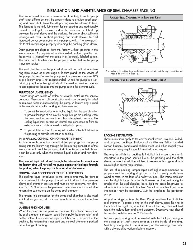
The proper installation and maintenance of packing to seal a pumpshaft is not difficult but must be properly done to provide good pack-ing and pump shaft sleeve life. All packing must be allowed to leak.This leakage is the only lubrication for the packing and additionallyprovides cooling to remove part of the frictional heat built upbetween the shaft sleeve and the packing. Failure to allow sufficientleakage will result in short packing and shaft sleeve life andincreased power consumption of the pumping unit. It is entirely possi-ble to stall a centrifugal pump by clamping the packing gland down.
Dean pumps are shipped from the factory without packing in theseal chamber. A complete set of die molded packing specified forthe service is shipped with the pump in a separately labeled carton.The pump seal chamber must be properly packed before the pumpis put into service.
The seal chamber may be packed either with or without a lanternring (also known as a seal cage or lantern gland) as the service ofthe pump dictates. When the pump section pressure is above 100psig a lantern ring is not recommended. When the pump is a self-priming type, the lantern gland should be used to provide a meansto seal against air leakage into the pump during the priming cycle.
PURPOSE OF LANTERN RINGLantern rings are made of Teflon or suitable metal as the servicedemands. They are of split construction and may be easily installedor removed without disassembling the pump. A lantern ring is usedin the seal chamber with packing for these reasons:
1) To permit the introduction of a sealing liquid into the seal chamberto prevent leakage of air into the pump through the packing whenthe pump suction pressure is less than atmospheric pressure. Thesealing liquid may be from an internal seal connection or from anexternal source. This is required on self-priming pumps.
2) To permit introduction of grease, oil or other suitable lubricant tothe packing to provide lubrication or cooling.
INTERNAL SEAL CONNECTION TO THE LANTERN RINGAn internal seal connection is used to inject pumpage from the pumpcasing into the lantern ring through the lantern ring connection of theseal chamber to seal the pump against air leakage as noted above.It can be used only when the pumped liquid is clean and non-abra-sive.
The pumped liquid introduced through the internal seal connection tothe lantern ring will not seal the pump against air leakage throughthe packing when the pump is idle or on stand-by service.
EXTERNAL SEAL CONNECTION TO THE LANTERN RINGThe sealing liquid introduced to the lantern ring may be from asource external to the pump. It must be introduced at a pressureabove seal chamber pressure and must be non-corrosive, non-abra-sive and 150°F or less in temperature. The connection is made to thelantern ring connections on the pump seal chamber.
The lantern ring connection on the pump seal chamber is also usedto introduce grease, oil, or other suitable lubricants to the lanternring.
LANTERN RING NOT USEDWhen the pump suction pressure is above atmospheric pressure orthe seal chamber is pressure sealed (no impeller balance holes) andneither internal nor external liquid or lubricant is required to thepacking, the lantern ring is not used and the seal chamber is packedfull with rings of packing.
PACKING INSTALLATIONThese instructions apply to the conventional woven, braided, folded,and wrapped packings. Packings of multifilament Teflon, braidedcarbon filament, compressed carbon sheet, and other special typesor materials may require special installation techniques.
The way in which the packing is installed in the seal chamber isimportant to the good service life of the packing and the shaftsleeve. Incorrect installation will lead to excessive leakage and maycause higher power requirements.
The use of a packing tamper (split bushing) is recommended toproperly seat the packing rings. Such a tool is easily made fromwood or metal in the form of a hollow cylinder. The inside diametermust be slightly larger than the shaft sleeve and the outside slightlysmaller than the seal chamber bore. Split the piece lengthwise toallow insertion in the seal chamber. More than one length of pack-ing tamper may be necessary. Suit the lengths to the particularpump.
All packing rings furnished by Dean Pump are die-molded to fit theseal chamber. To place a ring on the shaft sleeve, open the ring atthe split at the right angle to the plane of the ring. This will bestretain the molded form and avoid distortion. Successive rings shouldbe installed with the joints at 90° intervals.
Foil wrapped packing must be installed with the foil laps running inthe direction of shaft sleeve rotation on the inside of the ring.Metallic packing should be lubricated, on the wearing face only,with a dry graphite lubricant before insertion.
PACKED SEAL CHAMBER WITH LANTERN RING
PACKED SEAL CHAMBER WITHOUT LANTERN RING
S = When soft packing rings are furnished in a set with metallic rings, install the softrings in the locations marked “S”.
23
INSTALLATION AND MAINTENANCE OF SEAL CHAMBER PACKING

Foil wrapped packing sets are furnished with soft rings of fibrouspacking which are placed between the hard metallic rings in thelocations shown in the diagrams. These rings help to furnish lubrica-tion during the run-in period. Being soft, they are more sensitive tocompression loads and care must be taken during the adjustmentperiod.
Follow these steps:
1) With the packing gland slid back against the splash collar, place aring of packing on the shaft sleeve and enter it carefully into theseal chamber. Install a second ring, and a third ring if appropriate.Stagger all joints at 90° intervals. Follow the proper sequence ifhard and soft rings are used. Using a packing tamper in the sealchamber, slide the packing gland up on the packing gland studs,put on the gland stud nuts and tighten them evenly and firmly, seat-ing the packing rings firmly against the bottom of the seal chamber.This should make the shaft difficult to turn by hand.
2) Back off the gland stud nuts and the packing gland and remove thepacking tamper.
3) If a lantern ring is to be used, check the packing and pump specifications to determine its position and install it with the propernumber of rings of packing between it and the bottom of the sealchamber.
4) Continue to pack the pump with packing rings placed on the shaftsleeve until the seal chamber is nearly full and seat them firmly asabove. Packing ring joints should be staggered at 90° intervals.
5) Back off the gland stud nuts to finger tightness.
6) Rotate the pump shaft by hand to be sure it is not locked.
7) Final adjustment of the packing compression must be made withthe pump running. Start and stop the pump several times to begin
the running-in period. Allow sufficient leakage to assume goodlubrication during the adjustment. Pull up the gland stud nuts 1/8turn at a time. Allow a running in period between adjustments.Continue adjustment until the desired leakage control is reached.The minimum leakage rate depends on a number of things: liquidpumped, packing used, temperature, seal chamber pressure, andthe condition of the pump. In any case, some leakage is necessaryto both lubricate and cool the packing. Minimum rates may varyfrom a few drops per minute to as much as 1/2 pint per minute.
8) As the packing wears in service, the gland should be readjusted tomaintain the minimum leakage.
9) After the gland has been taken up to full travel, an additional ringof packing may be placed in the seal chamber. When the glandhas again been taken up to full travel the seal chamber should berepacked completely.
USUAL CAUSES OF PACKING FAILURE AND EXCESSIVE SEAL CHAMBER LEAKAGE1) Packing has not been installed properly.
2) Packing used is not suitable for the temperature and pressureinvolved or may be subject to attack by liquid handled.
3) Inner rings are not thoroughly seated in the seal chamber so thatouter rings are carrying all the load.
4) Dirt and foreign particles in seal chamber are causing rapid scor-ing of shaft sleeve.
5) Seal chamber cooling water not turned on.
6) Packing gland pulled up too tight.
When ordering additional packing sets, always refer to packing set num-ber and to pump serial number.
INSTALLATION OF STANDARD MECHANICAL SEALSClean, careful, and correct installation of the mechanical seal isessential to successful mechanical seal operation. Cleanliness andaccuracy of setting cannot be overemphasized.
For instructions on pump disassembly and assembly see the instruc-tion manual relating to the specific pump type.
A correct mechanical seal drawing is furnished with each pump andthe mechanical seal setting dimension is given on this drawing.
Use the setting for the specific pump type in which the installation isbeing made.
The pump is first assembled according to the applicable assemblyinstructions through the step of proper impeller adjustment.
The mechanical seal rotary unit must be properly located in relationto the face of the pump seal chamber in order to establish the properseal spring tension and resultant proper force on the seal faces. Anerror in setting of more than several thousandths of an inch may wellcause seal failure by excessive or insufficient seal face pressure.
INSTALLATION OF SINGLE INSIDE SEALSTo make the seal installation, with the pump partially assembled asnoted above, scribe a mark on the shaft sleeve (10) exactly in linewith the face of the pump seal chamber (Note 1). The impeller (3),and casing back cover (22) are now removed from the pump. If themark causes roughness on the shaft sleeve remove the burr carefully
with crocus cloth. Any roughness on the shaft sleeve may damagethe mechanical seal shaft packing when the seal is assembled.
Referring to the mechanical seal drawing, determine the proper “D”dimension for the seal and pump type. Measure carefully from themark which you have made on the shaft sleeve and make a newmark on the shaft sleeve, towards the pump end, exactly to thisdimension.
If the mechanical seal insert is of the clamped-in style, put themechanical seal gland (300) on the pump shaft and slide it backagainst the flinger. Put one mechanical seal gland insert gasket(325), the gland insert (315) and the other gland insert gasket (326)on the shaft. Make sure that the lapped face of the gland insert istowards the seal chamber.
Flexibly mounted inserts are two types, depending on the service ofthe pump. The insert may be of rectangular cross section grooved foran o-ring or it may be of L-shaped cross-section used with a Teflonmounting ring.
To position the o-ring mounted insert, lubricate the inside of themechanical seal gland. Place the o-ring in the groove of the insertand carefully slide the insert into position. Be careful not to damagethe o-ring. Make sure that the lapped face of the insert faces towardsthe pump.
24

To position the Teflon mounted insert, lubricate the inside of themechanical seal gland. Carefully slide the Teflon mounting ring intoposition in the gland and then slide the insert into place. The slot inthe stationary insert must index with the drive pin.
Put the mechanical seal gland and insert on the shaft and slide itback against the flinger. Be careful not to damage the insert or itsmounting. Put the gland gasket (324) on the shaft. Slide the sealrotary unit assembly carefully onto the shaft sleeve being particularlycareful not to damage the seal shaft packing (345). Be sure that theshaft sleeve hook is firmly against the shoulder on the shaft. Set therotary unit carefully to the setting mark you have made on the shaftsleeve and lock it tightly in place with the set crews. Recheck the set-ting. Slide the pump casing back cover carefully into place andguide the seal gland insert and gaskets together with the gland care-fully into position. Reassemble the pump. Now tighten the gland studnuts carefully and evenly to avoid cocking the gland, making surethat the gland insert and gaskets are in place.
Before starting the pump, bleed the air from the seal chamber. Theseal chamber must be full of liquid or the seal faces may be dam-aged by lack of lubrication when the pump is started.
Occasionally a seal may leak very slightly when the pump is firststarted. It the leakage continues more than a few moments the pumpshould be shut down and the seal removed to discover the cause.
Note 1—Pumps using a single inside balanced seal except Type609 (metal bellows) are furnished with a short shaft sleeve. Themark is made on the shaft because the sleeve does not extend tothis point. The second mark (setting mark) is made on the shaftsleeve and measured from the mark on the shaft.
INSTALLATION OF SINGLE OUTSIDE UNBALANCED SEALSIf the seal rotary unit is scribed with a setting mark, the shaft markingprocedure outlined below may be omitted. The setting mark can befound on the outer shell of the rotary unit running circumferentiallybetween the four round holes in the shell. Visible through each holeis the edge of the metal disc against which the seal springs bear. Toset the seal with the proper spring pressure, first assemble the pumpas noted below with the seal rotary unit slid back against the shaftsplash collar and left loose until the entire bearing housing-impellerassembly is bolted in place in the pump casing. Then slide the sealrotary unit into place against the stationary insert and compress thesprings until the metal disc visible through the holes is aligned withthe setting mark scribed on the shell. Tighten the set screws andcheck through each hole to determine that the seal rotary unit is cor-rectly compressed and not cocked.
If the seal rotary unit is not marked with a setting line, a setting markmust be made on the shaft sleeve. To make the seal installation, withthe pump partially assembled as noted above, scribe a mark on theshaft sleeve (10) exactly in line with the face of the pump seal cham-ber. The impeller (3), and casing back cover (22) are now removedfrom the pump. If the mark causes roughness on the shaft sleeveremove the burr carefully with crocus cloth. Any roughness on theshaft sleeve may damage the mechanical seal shaft packing whenthe seal is assembled.
Referring to the mechanical seal drawing, determine the proper“D” dimension for the seal and pump type. Measure carefully fromthe mark which you have made on the shaft sleeve and make anew mark on the shaft sleeve, towards the bearing housing, exactlyto this dimension. Remove the burr if necessary. This mark is theseal setting mark.
Put the mechanical seal rotary unit on the shaft and slide it backagainst the splash collar. Assemble the seal insert gasket (326), themechanical seal insert (315), and seal insert gasket (325) to the faceof the seal chamber and, placing the gland (300) in position, pulldown the gland stud nuts tightly and evenly. Make sure that thelapped face of the seal insert is towards the rotary unit. Reassemblethe pump. Now carefully slide the rotary unit against the seal insert,compress the rotary unit and set it to the mark on the shaft sleeveand lock the rotary unit tightly in place with the set screws. Be carefulnot to cock the rotary unit.
Before starting the pump, bleed the air from the seal chamber. Theseal chamber must be full of liquid or the seal faces may be dam-aged by lack of lubrication when the pump is started.
Occasionally a seal may leak very slightly when the pump is firststarted. If the leakage continues more than a few moments the pumpshould be shut down and the seal removed to discover the cause.
INSTALLATION OF DOUBLE INSIDE UNBALANCED SEALSTo make the seal installation, with the pump partially assembled asnoted above, scribe a mark on the shaft sleeve (10) exactly in linewith the face of the pump seal chamber. The impeller (3) and casingback cover (22) are now removed from the pump. If this marking orsubsequent marking causes roughness on the shaft sleeve remove theburr carefully with crocus cloth. Any roughness on the shaft sleevemay damage the mechanical seal shaft packing when the seal isassembled.
Referring to the mechanical seal drawing, determine the two “D”dimensions for the two rotary units. Be sure to determine those for theparticular pump type. Measure carefully from the mark which youhave made on the shaft sleeve and make two new marks on theshaft sleeve, towards the pump end, exactly to these dimensions.
Double seal stationary inserts are two types depending on the ser-vice conditions of the pump. The insert may be of rectangular crosssection grooved for an o-ring or the insert may be of L-shaped crosssection used with a Teflon mounting ring.
To position the o-ring mounted insert, lubricate the inside of the sealchamber and the inside of the mechanical seal gland. Place the o-rings in the grooves and carefully slide the inserts into position inthe seal chamber and seal gland. Be most careful not to damage the o-ring.
To position the Teflon mounted insert, lubricate the inside of the sealchamber and the inside of the seal gland. Carefully slide the Teflonmounting rings into position and then slide the stationary inserts intoplace. The slots in the stationary inserts must index with the drive pins.
Put the mechanical seal gland, with insert installed, on the pumpshaft sleeve and slide it back against the splash collar. Put the sealgland gasket on the sleeve and slide it back against the gland. Slideone seal rotary unit on the sleeve with the carbon face towards thebearing housing. Be careful not to damage the seal shaft packing.Be sure that the shaft sleeve hook is firmly against the shoulder on theshaft. Set the rotary unit carefully to its setting mark on the shaftsleeve and lock it tightly in place with the set screws. Slide the sec-ond rotary unit onto the shaft sleeve with the carbon face away fromthe bearing housing. Set it carefully to its setting mark and lock ittightly in place. Recheck both rotary settings and correct if necessary.Slide the pump casing back cover very carefully in place over theseals. Slide the gland gasket and seal gland into place and carefullyand evenly tighten the gland stud nuts. Do not cock the gland. Thepump may now be reassembled.
25

Double seals require a liquid in the seal chamber between the sealinserts to provide lubrication. This barrier liquid must be supplied at apressure of 10 to 15 psi above seal chamber throat pressure to activate the inboard seal. Before starting the pump, be sure that theseal chamber is full of this lubrication and that all supply lines for thisliquid are in place and in operation.
Leakage from the outboard seal can be easily spotted. Leakagethrough the inboard seal can be detected only by the loss of the bar-rier (lubricating) liquid from between the seals. If leakage occurs, thepump must be disassembled and the cause of leakage determined.
If you do not have the correct mechanical seal drawing, write to thefactory giving complete information on pump size, type, and serialnumber and the correct seal drawing will be sent.
To avoid prolonged down time and facilitate rapid repair of dam-aged pump parts, Dean recommends that the pump user maintain aminimum stock of spare parts. If the pump service is critical or thepump parts are of special materials, spare parts stock is even moreimportant to the user. Such spares inventory may extend from aspare mechanical seal or seal parts through complete casing backcover-impeller-bear ing housing assemblies prepared for immediateinsertion in the pump casing. Consult your Dean representative whowill assist you in selecting your spares stock.
Only Dean Authorized Service Parts shall be used.
ORDERING SPARE PARTSSpare part orders will be handled with a minimum delay if the fol-lowing information is furnished by the customer with the order:
1) Give the pump serial number and size. These may be found on thepump name plate. The serial number is also stamped on the suc-tion flange or the top edge of the bearing housing front flange.
2) Give the part name, part number, and material of part. Theseshould agree with the standard parts list.
3) Give the quantity of each part required.
4) Give complete shipping instructions.
SPARE PARTS
The preceding general and descriptive information for pH Seriespumps also applies to the pHP Series pumps. Special variations aredescribed below.
INSTALLATIONSuction piping to a self priming pump must be free of air leaks. If it isnot, the pump will not prime. Suction piping should be as short anddirect as possible. Long horizontal runs should be avoided. The lesssuction piping, the less chance for air leaks. Flanged joints may becoated with a rubber compound to avoid leaks at these points.
In applying a self-priming pump, consideration of the discharge pip-ing is necessary. The air from the pump casing must be expelledwithout being compressed substantially above atmospheric pressure.Although a self-priming pump will prime against a small dischargepressure, the priming time will increase and, if the pressure is highenough, it will not permit the pump to prime.
If the pump expels air into an empty discharge system, there is morethan adequate volume available to contain the discharged air. If thedischarge line contains a check valve, it should be located a dis-tance away from the pump so as to leave a volume in the dischargeline (between the pump and the check valve) equal to about half thevolume of the suction line.
If the check valve must be installed closer to the pump, install avalved line from the pump discharge system back to the suctionsource. This is left open during the priming cycle and closed whenpriming is accomplished and during pumping. The check valve mustbe installed in the pump discharge line downstream from the bypassconnection.
If the pump is fitted with a double mechanical seal a barrier liquidmust be supplied at a pressure 10-15 pounds above seal chamberpressure when the pump is pumping.
If seal chamber packing is used it must include a lantern ring.Sealing liquid compatible with the pumpage must be supplied under
pressure to the lantern ring connection in the seal chamber of thepump.
Air leaks through the mechanical seal or packing will prevent pumppriming.
OPERATIONA self priming pump requires an initial prime after installation andbefore normal operation. Be sure the end of the suction piping isproperly immersed in the liquid to be pumped. Remove the primingplug in the top of the casing. Use a liquid which is compatible withthe normal pumpage. Pour this into the pump casing until the liquidlevel stops rising. Any excess is going out of the pump through thesuction opening. Replace the priming plug and tighten it securely.Start the pump and let it prime. Stop the pump. There will now be aquantity of pumpage retained in the special casing. This will permitthe pump to reprime thereafter.
If during the initial prime or repriming, the pump runs without actual-ly priming, there are two possible causes. The first of these is an airleak in the suction piping. A very small hole is a major air leak andwill prevent priming. A leak of air into the seal chamber will likewiseprevent priming, air being constantly drawn into the pump.
MAINTENANCEThe maintenance of this pump is that described in the manual towhich this addendum is attached. Lubrication, installation, disassem-bly and assembly instructions therein apply to the pHP pump. Theonly difference is the shape of the casing.
Unlike the standard centrifugal pump casing, the pHP self primingpump casing retains liquid. Care should be taken to drain the casingthoroughly before the pump is removed from the line.
When a pump has been removed from the line and replaced, theinitial prime described above will be necessary before normal pumpoperation.
INSTALLATION, OPERATION AND MAINTENANCE PHP SELF-PRIMING PUMPS
26

Dean Pump Serial Number ServicePlant Property Number LocationCapacity ; T.D.H. ; Imp. Dia. ; Temp. ; RPMMaterials of Construction: Casing ; Impeller ; Shaft ; Shaft Sleeve
Spare Parts in Plant Stock Room
Interchangeable with Dean Serial Numbers
CUSTOMER’S PLANT MAINTENANCE RECORD
27
PHP2140
SECTION NO.01947C
PHP2110
SECTION NO.01951B

Read the instruction manual completely, before installing, filling, operating, or maintaining this equipment.Obtain, read, and heed the MSDS (Material Safety Data Sheet) for the fluids being handled before attempting tofill, operate or maintain this equipment.Obtain instructions from the Safety Engineer responsible for your facility before performing any work on the pump-ing equipment and systems.APPLICATION AND REAPPLICATION - At the time of installation, the equipment received should have alreadybeen selected for the service required. You must read the paperwork for the installation and check serial number ofthe pump to assure that you are installing the correct pump into the service for which it was selected.Many pumps look identical from the outside but can be made of different materials and/or be constructed differentlyinside. Personal injury, death, equipment damage, product (pumpage) damage, and/or product loss could occur ifthe incorrect pump is installed.Do not transfer an existing pump to any other service conditions until you have thoroughly reviewed the pump construction, materials, sizing, sealing, pressure containing capability, head/capacity capability, and temperature capability with respect to the required service. Consult your DEAN PUMP sales engineer with all theservice requirements and a full description of the existing pump (including the serial number), seal, and sub-systemsso that we can assist you in a successful reapplication.INSTALLATION - Always wear the appropriate protective apparel when working on or around the pumping equip-ment. Safety glasses with side shields, heavy work gloves (use insulated work gloves when handling hot items), steeltoed shoes, hard hat, and any other protective gear as needed for protection. One example of other gear would be breathing apparatus when working near toxic materials.Use lifting devices, manufactured expressly for the purpose of lifting, to move the pumping machinery. Do notattempt to lift the assembly or its components manually. Use only devices with lifting capabilities in excess of theweight of the unit being lifted. Inspect straps,chains, hooks, etc. for damage and lifting capability before use. Liftonly at the center of gravity.Personal injury, death, and/or equipment damage could occur if good lifting practices are not used.Install the equipment on a properly designed and built foundation. Assure that the driver (motor, turbine,or engine)shaft is properly aligned to the pump shaft.Connect the suction and discharge piping without forcing the piping into position. The pipe flanges must line upwith the pump flanges “freely”. Strain caused by “forcing” and/or misalignment may cause failure of the pumpingunit, flanges, and/or the piping resulting in fluid (pumpage) release. This could cause personal injury, deathand/or damage to this and/or other equipment.Install a “new” bolt, of the correct size per ASME/ANSI B16.5 and the correct material per ASME/ANSI B16.5,in every bolt hole. Tighten all bolts evenly. Use only new uncorroded fasteners.Improper flange bolting may cause failure of the pumping unit, flanges, piping, and/or fluid (pumpage) releasewhich could cause personal injury, death, and/or damage to this and/or other equipment.Connect all other (auxiliary) piping necessary for safe and successful operation of the equipment in the specific ser-vice conditions of the application. Make sure that all piping is installed into it’s correct connection. Installation of apipe into an incorrect location could result in an explosion and personal injury or death as well as damage to thisand/or other equipment.Install pressure relief valves in any cavities that could be subjected to pressures in excess of the allowable workingpressure of that cavity. Explosion, personal injury, death, and/or damage to this and/or other equipment mayoccur if pressure exceeds allowable.Recheck the alignment between the driver (motor, turbine, or engine) and pump shafts. Installation of piping may haveforced the pump out of alignment. If so, correct the piping to remove the distorting load.Check to be certain that the shaft coupling spacer is not installed, and then gently bump the motor starter to checkthe rotational direction of the motor. If this is not in the direction of rotation required for the pump, make the neces-sary corrections.Lock-out the power to the driver (motor, turbine, engine, etc.)Install the shaft coupling spacer. Be sure that you install all the retaining devices and bolts and that they are tight.Read and comply with the coupling manufacturer’s instructions. Personal injury, death, and/or equipment damagecould occur if the coupling spacer is not properly installed. Remove all debris and tools from the area near theshafts and the shaft coupling. Do this to assure that nothing is caught and thrown by the rotating parts when thepump is started. Bolt the coupling guard securely to the baseplate, checking to assure that it is not contacting anyparts that will rotate when the pump is started.FILLING - Before filling the pump with liquid, check to see that all possible leak locations are sealed. See that all ofthe connections into the pressure containing cavity are sealed or connected to a related piping system that also hasall possible leak paths sealed. Do not plug unused jacket cavities, as this could develop dangerous pressure build-up. Use a wrench on all bolted joints to apply torque to assure that all gaskets are sealed in a tight joint. Check tosee that all threaded pipe connections are also tight enough to seal the liquid pressure that will be applied whenthe system is started.OPERATING - Before starting the unit, see that all personnel are a safe distance away from all possible hazards,that all sub-systems are connected and operating, that all debris has been removed, that the shaft coupling guard issecurely in place, and that the pump is full of liquid.Do not operate this pump at shut-off (no flow) as an explosion may result. This can occur with any liquid, even“cold water”. Personal injury, death, equipment damage, and/or loss of product (pumpage) is likely to occur. If yoursystem is operated where it is possible for all outlets for the discharge from the pump to be closed while the pumpis still operating, a modification of the system needs to be made to assure a continual flow of pumpage through thepump. Note that some people have a belief that a bypass line from the discharge side of the pump to the suctionside of the pump will relieve this problem, this is “NOT TRUE”; DO NOT ATTEMPT THIS.MAINTENANCE, DISASSEMBLY AND REPAIR - Work must be performed only by thoroughly trained and quali-fied personnel to assure quality repair and to reduce the possibilities of injury to personnel and/or damage toequipment. If you do not have personnel who are capable of safe quality repair of this equipment, we advise youto return the equipment to DEAN PUMP to be repaired.When it is necessary to open the pump and/or the pumping system, the fluid will be exposed to the atmosphereand personnel in the area. For the safety of all involved, the risk of exposure of personnel to the hazards of thepumpage can be reduced by flushing the entire system with a compatible non-toxic, non-hazardous,stable liquidbefore opening the pump or the system. In all cases, where the system is flushed or not, use the utmost care aroundthe pumpage and the pumping system.Always wear the appropriate protective apparel when working on or around the pumping equipment. Safetyglasses with side shields, heavy work gloves (use insulated work gloves when handling hot items), steel-toed shoes,hard hat, and any other protective gear as needed for protection. One example of other gear would be breathing apparatus when working near toxic materials.Use only top quality tools.
Stop the pump. Turn off the power supply (electricity, steam, etc.) to the pump driver (motor, turbine, engine, etc.)and lock the switching device so that it cannot be restarted. Tag the switching device so that no one will attempt torestart the unit.Close the suction and discharge valves completely to isolate the pump from the system. Lock the valves in theclosed position and tag them so that no one will attempt to open them.Turn off, lock out, and tag all sub-systems and auxiliary equipment and auxiliary supply lines to isolate the pumpingunit from any and all power, energy, and/or fluids.Do not attempt to perform any work on the unit until you are confident that the pump and its contents have beenstabilized at ambient temperature, and atmospheric pressure.Put on protective wear to protect human tissue from attack by the fluids contained in the pump and any sub-systems,and from any vapors or fumes that could possibly be released from these fluids. This could mean breathing apparatus,face shields, heavy long sleeve rubber gloves, rubber apron, hood, and possibly more, dependent of course on theproperties of the fluids involved and the installed drain and vent piping arrangement. Personal injury and/or deathcan occur if adequate precautions are not taken with regard to the fluid, the installation, and the possibilities of therelease of fluid, vapors, and/or fumes.Remove the coupling guard. Remove the coupling spacer.Drain all the fluids from the auxiliary sub-systems (lubrication, cooling, heating, seal barrier, etc.) that are connect-ed to the pump. Drain each fluid into a separate container. Use caution required for each fluid after reading theMSDS (Material Safety Data Sheet) for each.Flush each sub-system with a compatible, non-toxic, non-hazardous, stable liquid. Drain into individual containersfor each fluid. Disconnect and remove all auxiliary piping.Carefully bleed off any pressure remaining in the pump. Pressure remaining in the pump will be dependent uponthe pressure in the system when the pump was stopped; the quality, type, and condition of the isolation valves; thethermal expansion valves of the fluid and the pump material; and the change in the vapor pressure of the fluidbetween the temperature at the time the isolation valves were closed and the ambient temperature. Bleeding mustbe through a valved drain line piped to a closed container mounted lower than the pump. The container must bearranged with a relief passage to some point where pressure and fumes will not be harmful to personnel. The container must also have a level device so that determination can be made that sufficient fluid has been drained toempty the pump cavity and the volume of fluid that was contained in the run of suction and discharge pipebetween the isolation valves and the pump. After the initial rush of fluid from the pump relieves the pressure, thedrain valve can be opened further to speed the draining operation. When fluid quits running into the drain tank,gauge the volume to see if it is sufficient to have fully drained the contents of the pump and the suction and dis-charge pipes between the isolation valves.If the system was constructed without any drain connections, it will be necessary to consult the designers of the systemfor safe draining procedures.Now drain any small piping, that contains the fluid pumped, from all low points, into the same container used todrain the pump. Do not drain any other fluids (different than the pumpage) into this container as they may not be compatible. Personal injury, death, and/or equipment damage could occur.Even though it might appear that, the cavity being drained has completely drained, be extremely careful about opening the system and/or opening the pump. If something solid in the pumpage moves to the vicinity of the drainconnection, it could seal-off the drain and maintain pressure in the cavity thought to have been drained. It is also possible that the isolation valves are not sealing and therefore allowing liquid to flow from the system into the pump.Personal injury, death, and/or equipment damage may occur if intense caution is not exercised.Because of the above possibility, when you loosen the gasketed joint at the back of the casing (5), loosen the bolts ornuts only one full turn, and then use jack screws to break the gasket seal. If fluid and/or pressure remains in the pump,it will spray out now. Use extreme caution, wearing protective gear, to avoid injury. Do not proceed with disassem-bly until leakage ceases completely. If leakage does not cease, the isolation valves may not be sealing. Note that ifthe pump was purchased with out a drain, the pump will contain fluid which will flow out at the time the bolts areloosened and the gasket seal is broken. When you open the pump, the fluid will be exposed to the atmosphere and personnel in the area. For the safety ofall involved, the risk of exposure can be reduced by flushing the cavity that was just drained, with a compatiblenon-toxic, non-hazardous, stable liquid, before disassembling the pump.Remove the casing bolts or nuts and using mechanical lifting apparatus to support the weight, pull the rotating unitfrom the casing.Flush the wetted parts now exposed with compatible, non-toxic, non-hazardous, stable liquid.Remove the gasket from the face of the casing (5) or the bearing housing (26) dependent on which one the gasketmay have adhered to. The type of gasket and material of construction will vary with service requirements. Attack byprying and then, if necessary, layering off the old gasket with a sharp scraper, attempting to remove it in the largestpossible pieces. Wear heavy leather, long sleeve work gloves when using the scraper. Wet the gasket before andduring the scraping operation to reduce the possibility of fibers becoming airborne. Wear a respirator during thisoperation and until all debris has been disposed of in a plastic bag. Remove all of the gasket material down to cleanmetal surfaces on both parts that contacted the gasket. Place all of the gasket residue in a plastic bag, seal the bagand dispose of it in compliance with all government requirements.The rotating assembly of the pump can now be moved to a more convenient location for further disassembly. Useonly high quality tools. Flush parts as disassembled to removed hazardous residue from the pumpage and/or sub-system fluids.Wear protective equipment as advised at the beginning of these warnings.Use mechanical lifting equipment to lift assemblies and components.Do not apply heat to parts to assist in disassembly. Explosion could occur causing personal injury, death, and/ordamage to equipment.Do not attempt to drill, saw, or otherwise cut parts to remove them. Explosion and/or fuming could occur causingpersonal injury, death, and/or equipment damage.Do not hammer on any parts. Personal injury and/or damage to equipment may occur.Do not attempt to manufacture parts or modify Dean Pump parts in any manner. Death, personal injury, and/ordamage to equipment may occur.One example of the above would be overboring the seal chamber, which removes metal that is required to con-tain fluids. Removal of this metal reduces the pressure containing capability of the part, and may create a leak paththrough the part.Replace all gaskets, seals, bearings, and lubricants. Replace all parts that have worn, corroded, eroded, or other-wise deteriorated.Use only Dean Pump Division of Met-Pro Corporation parts.
HAZARDOUS SITUATIONS MAY OCCUR UNLESS THIS EQUIPMENT IS APPLIED, INSTALLED, OPERATED, AND MAINTAINED BY THOROUGHLY QUALIFIED PERSONNEL IN STRICT ACCORDANCE WITH THE INSTRUCTION MANUAL AND ALL APPLICABLE DRAWINGS AND CODES.
READ WARNINGS
6040 Guion Road • Indianapolis, IN 46254(317) 293-2930 • FAX: (317) 297-7028E-mail: [email protected] • Web Site: www.deanpump.com
MET-PROA Met-Pro Fluid Handling Technologies Business
Combining the Resources of Dean Pump, Fybroc & Sethco
Global Pump Solutions
©COPYRIGHT 2012 MET-PRO CORPORATION, DEAN PUMP DEAN PUMP® IS A REGISTERED TRADEMARK OF MET-PRO CORPORATION. 09-5924 512