metal blind - smith and noble llc
TRANSCRIPT

INSTALLATIONINSTRUCTIONS
METAL BLIND
SHIM
BEFORE MOUNTING THE BLIND
HARDWARE INCLUDED
TOOLS NEEDED
FASTENERS FOR OTHER SURFACES
Please take a few minutes to read theseinstructions. When properly installed, yourRoulett Blind will provide many years of beauty and dependable service.
Hinged-CoverInstallation BracketsMounting ScrewsSupport Brackets(For larger blinds)Valance Clips
Optional Hardware:(If ordered)
• Extension Brackets• Spacer Blocks• Hold-down Brackets• Hidden Cam Brackets
Pencil Drill LevelScrew Driver Drill Bits
screws provided are for mounting the blindto a wood surface only. For other surfaces, use the following:
Wallboard or Plastic - Pre-drill holes forsuitable hollow wall anchors or toggle bolts.Metal Surfaces - Pre-drill holes and use shortmetal screws.For Concrete, Stone, Brick or Tile -Use a carbide drill and appropriate plugs, or anchor with screws.
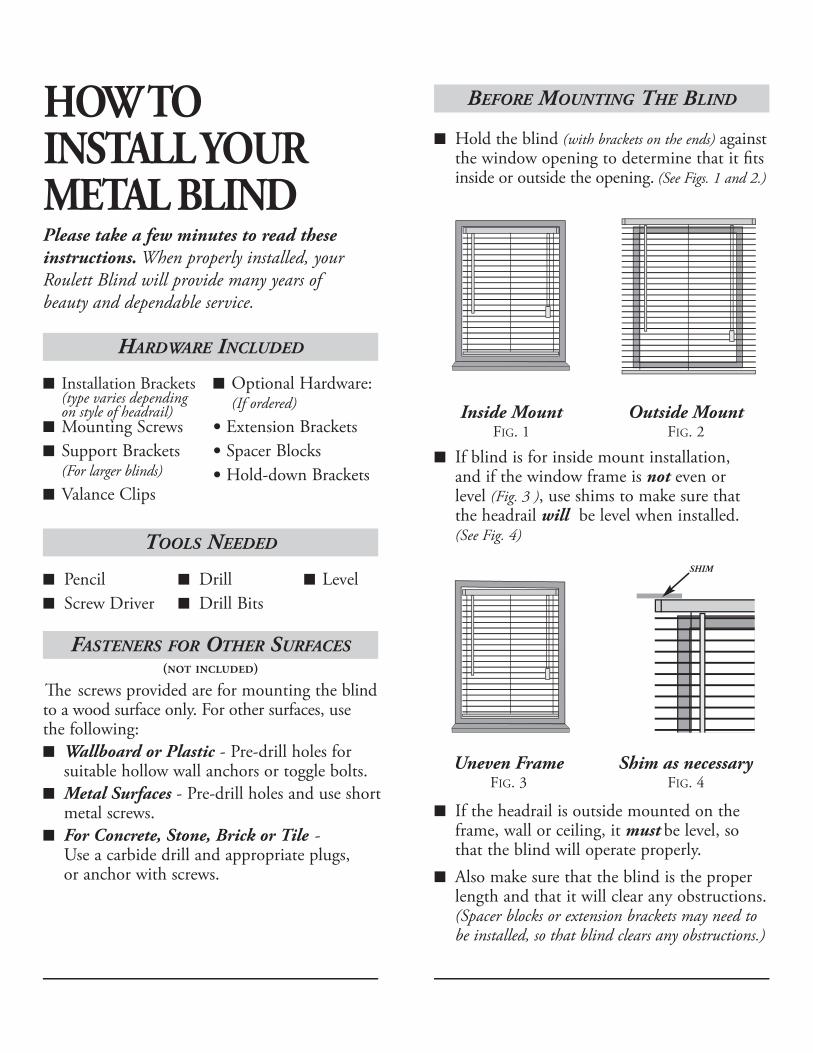
Hold the blind (with brackets on the ends) againstthe window opening to determine that it fits inside or outside the opening. (See Figs. 1 and 2.)
If blind is for inside mount installation, and if the window frame is not even or level (Fig. 3 ), use shims to make sure that the headrail will be level when installed.(See Fig. 4)
If the headrail is outside mounted on theframe, wall or ceiling, it must be level, sothat the blind will operate properly. Also make sure that the blind is the properlength and that it will clear any obstructions.(Spacer blocks or extension brackets may need tobe installed, so that blind clears any obstructions.)
Inside MountFIG. 1
Outside MountFIG. 2
Uneven FrameFIG. 3
Shim as necessaryFIG. 4
(NOT INCLUDED)
HOW TO INSTALL YOUR METAL BLIND
Installation Brackets(type varies depending on style of headrail)
�e
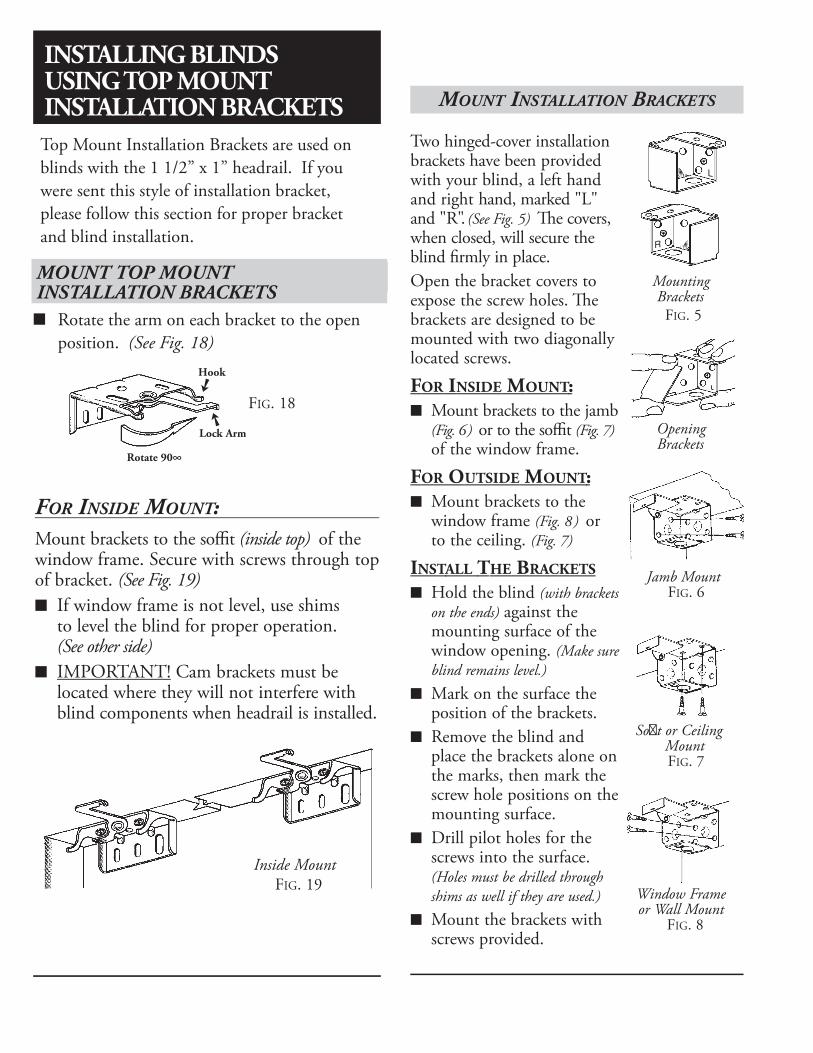
FIG. 9
MOUNT INSTALLATION BRACKETS EXTENSION BRACKETS / SPACER BLOCK
SUPPORTING WIDE BLINDS
Two hinged-cover installationbrackets have been providedwith your blind, a left handand right hand, marked "L"and "R". (See Fig. 5) �e covers,when closed, will secure theblind firmly in place.Open the bracket covers toexpose the screw holes. �ebrackets are designed to bemounted with two diagonallylocated screws.
FOR INSIDE MOUNT:Mount brackets to the jamb(Fig. 6) or to the soffit (Fig. 7)of the window frame.
FOR OUTSIDE MOUNT:Mount brackets to the window frame (Fig. 8) or to the ceiling. (Fig. 7)
INSTALL THE BRACKETS
Hold the blind (with bracketson the ends) against themounting surface of thewindow opening. (Make sureblind remains level.)Mark on the surface theposition of the brackets.Remove the blind andplace the brackets alone onthe marks, then mark thescrew hole positions on themounting surface.Drill pilot holes for thescrews into the surface.(Holes must be drilled throughshims as well if they are used.)Mount the brackets withscrews provided.
MountingBrackets
FIG. 5
OpeningBrackets
FIG. 5
If Extension Brackets (Fig. 9) were ordered, theymust be attached to the mounting surface first�en bolt the installation brackets to the extension. (See Fig. 9) Note: Center supportbrackets for larger blinds will also need to be attached using extensions.
Blinds wider than 48" require Center SupportBrackets. Blinds over 72" wide will require 2 support brackets. Do not space supportbrackets more that 48" apart. Do not positionsupport brackets where they will interfere withthe lift cords and braided ladders. (On three-ladder blinds, install support bracket two inches to the left or right of center.)
Align support brackets with the installationbrackets. (See Fig 11). Mark screw holes onmounting surface. Drill pilot holes for screwsand attach the support brackets. (Note: For inside and ceiling mounts, the frontsof the brackets must line up.)
If Spacer Blocks (Fig. 10) are used, attach the installation brackets to the mounting surfacethrough the spacer blocks.
L
R
Jamb MountFIG. 6
So�t or CeilingMountFIG. 7
Window Frameor Wall Mount
FIG. 8
FIG. 10
Extension Bracket withInstallation Bracket
Extension Bracket withCenter Support Bracket
Align Center SupportBracket with Installation Brackets
FIG. 11
Use Extension Bracketand Spacer Block
to clear obstructions
MOUNT HIDDEN CAM BRACKETS
Rotate the Lock Arm on each Hidden CamBracket to the open position. (See Fig. 18)
FIG. 18
Inside Mount FIG. 19
Hook
Lock Arm
Rotate 90∞
INSTALLING BLINDS USINGOPTIONAL HIDDEN CAMBRACKETS
If ordered, blinds will be supplied withHidden Cam Brackets instead of Hinged-Cover Brackets. Wider blinds will includeadditional cam brackets in place of supportbrackets.
FOR INSIDE MOUNT:Mount brackets to the soffit (inside top) of thewindow frame. Secure with screws through topof bracket. (See Fig. 19)
If window frame is not level, use shims to level the blind for proper operation. (See other side)IMPORTANT! Cam brackets must belocated where they will not interfere withblind components when headrail is installed.
INSTALLING BLINDS USING TOP MOUNT INSTALLATION BRACKETSTop Mount Installation Brackets are used on blinds with the 1 1/2” x 1” headrail. If you were sent this style of installation bracket, please follow this section for proper bracket and blind installation.
MOUNT TOP MOUNT INSTALLATION BRACKETS
Rotate the arm on each bracket to the open position. (See Fig. 18)

FIG. 9
MOUNT INSTALLATION BRACKETS EXTENSION BRACKETS / SPACER BLOCK
SUPPORTING WIDE BLINDS
Two hinged-cover installationbrackets have been providedwith your blind, a left handand right hand, marked "L"and "R". (See Fig. 5) �e covers,when closed, will secure theblind firmly in place.Open the bracket covers toexpose the screw holes. �ebrackets are designed to bemounted with two diagonallylocated screws.
FOR INSIDE MOUNT:Mount brackets to the jamb(Fig. 6) or to the soffit (Fig. 7)of the window frame.
FOR OUTSIDE MOUNT:Mount brackets to the window frame (Fig. 8) or to the ceiling. (Fig. 7)
INSTALL THE BRACKETS
Hold the blind (with bracketson the ends) against themounting surface of thewindow opening. (Make sureblind remains level.)Mark on the surface theposition of the brackets.Remove the blind andplace the brackets alone onthe marks, then mark thescrew hole positions on themounting surface.Drill pilot holes for thescrews into the surface.(Holes must be drilled throughshims as well if they are used.)Mount the brackets withscrews provided.
MountingBrackets
FIG. 5
OpeningBrackets
FIG. 5
If Extension Brackets (Fig. 9) were ordered, theymust be attached to the mounting surface first�en bolt the installation brackets to the extension. (See Fig. 9) Note: Center supportbrackets for larger blinds will also need to be attached using extensions.
Blinds wider than 48" require Center SupportBrackets. Blinds over 72" wide will require 2 support brackets. Do not space supportbrackets more that 48" apart. Do not positionsupport brackets where they will interfere withthe lift cords and braided ladders. (On three-ladder blinds, install support bracket two inches to the left or right of center.)
Align support brackets with the installationbrackets. (See Fig 11). Mark screw holes onmounting surface. Drill pilot holes for screwsand attach the support brackets. (Note: For inside and ceiling mounts, the frontsof the brackets must line up.)
If Spacer Blocks (Fig. 10) are used, attach the installation brackets to the mounting surfacethrough the spacer blocks.
L
R
Jamb MountFIG. 6
So�t or CeilingMountFIG. 7
Window Frameor Wall Mount
FIG. 8
FIG. 10
Extension Bracket withInstallation Bracket
Extension Bracket withCenter Support Bracket
Align Center SupportBracket with Installation Brackets
FIG. 11
Use Extension Bracketand Spacer Block
to clear obstructions
INSTALL HEADRAIL INTO BRACKETS
Snap the Valance Clipsonto the headrail before inserting it into the brackets. Each blind requires the same number of clips as there are braided ladders. Do not position clips where they will interfere with headrail componentry. (Fig. 12)
FIG. 13
Slide the headrail into the brackets. (Fig. 13)
"Snap" Cover Closed
Headrail
ValanceValance Clip Valance Clip
TOP VIEW
VFIG. 12
Headrail
Valance Clip
Headrail
Close the hinged covers on the installation brackets. (Make sure the covers are lockedso that the blind is secure.)(Fig. 14) FIG. 14
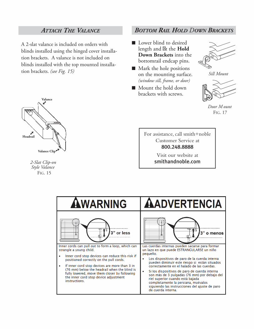
BOTTOM RAIL HOLD DOWN BRACKETS
Lower blind to desiredlength and �t the HoldDown Brackets into thebottomrail endcap pins. Mark the hole positions on the mounting surface.(window sill, frame, or door)Mount the hold downbrackets with screws.
ATTACH THE VALANCE
�e Valance included with your blind is one of two styles.
For Standard 2-Slat Valance:Snap each slat into the slots of the valanceclips. (See Fig. 15)For Deluxe Groover 2-Slat Valance:Snap the groover/slat assembly into the top andbottom slots of the valance clips. (See Fig. 16)
2-Slat Clip-on Style Valance
FIG. 15
Valance
Valance Clip
Headrail
Deluxe Groover2-Slat Valance
FIG. 16
Valance
Headrail
Door M ount FIG. 17
Sill Mount
A 2-slat valance is included on orders with blinds installed using the hinged cover installa-tion brackets. A valance is not included on blinds installed with the top mounted installa-tion brackets. (see Fig. 15)
For assistance, call smith+nobleCustomer Service at
800.248.8888
Visit our website atsmithandnoble.com

For assistance, call smith+nobleCustomer Service at
800.248.8888
Visit our website atsmithandnoble.com
Warranty
All Smith+Noble shades are designed for a lifetime of trouble-free use and is covered by a limited lifetime warranty. This warranty applies to the original customer/installation with proof of purchase and covers any defects in materials or workmanship provided that the product is
measured and installed according to the product instructions.
In the unlikely event that warranty service is ever needed, simply call Customer Service at 800.248.8888. Our customer service representatives
will arrange for a repair as quickly as possible.
© 2013 Smith+Noble Home. All Rights Reserved