metal-casting processes and equipment · metal-casting processes and equipment ch 11 . the major...
TRANSCRIPT
Hail University
College of Engineering
Department of Mechanical Engineering
Metal-Casting Processes and Equipment
Ch 11
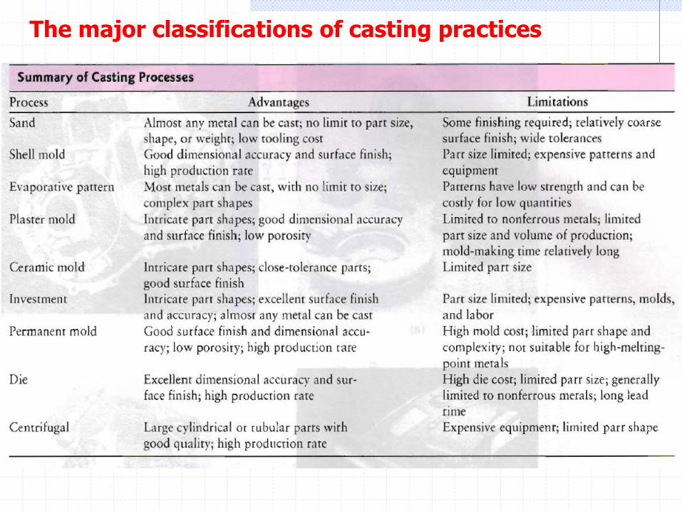
The major classifications of casting practices
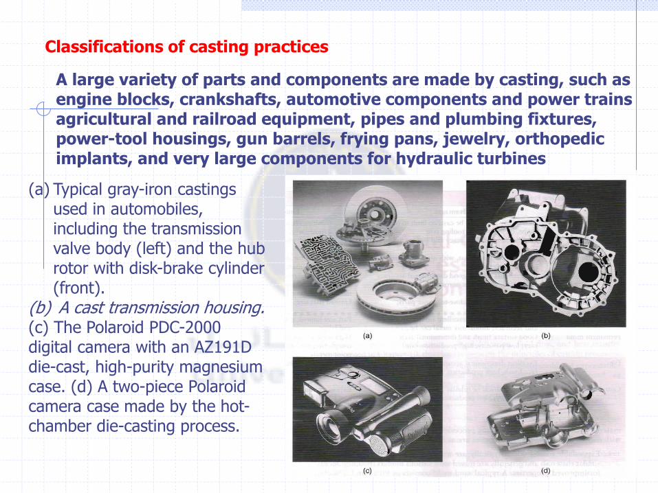
A large variety of parts and components are made by casting, such as engine blocks, crankshafts, automotive components and power trains agricultural and railroad equipment, pipes and plumbing fixtures, power-tool housings, gun barrels, frying pans, jewelry, orthopedic implants, and very large components for hydraulic turbines
(a) Typical gray-iron castings used in automobiles, including the transmission valve body (left) and the hub rotor with disk-brake cylinder (front).
(b) A cast transmission housing. (c) The Polaroid PDC-2000 digital camera with an AZ191D die-cast, high-purity magnesium case. (d) A two-piece Polaroid camera case made by the hot-chamber die-casting process.
Classifications of casting practices

These classifications are related to mold materials, pattern production, molding processes, and methods of feeding the mold with molten metal
The major classifications of casting practices
The major categories are as follows:
1. Expendable molds
which typically are made of sand, plaster, ceramics, and similar materials and generally are mixed with various binders (bonding agents) for improved properties.
2. Permanent molds
Which are made of metals that maintain their strength at high temperatures.
3. Composite molds
Which are made of two or more different materials (such as sand, graphite, and metal) combining the advantages of each material.


Expendable-mold, Permanent-pattern Casting Processes
The major categories of expendable-mold, permanent-pattern casting processes are sand, shell mold, plaster mold, ceramic mold, and vacuum casting.
1-Sand Casting
The traditional method of casting metals is in sand molds and has been used for millennia. Sand casting is still the most prevalent form of casting; in the United States alone, about 15 million tons of metal are cast by this method each year.

Outline of production steps in a typical and-casting operation
1-Sand Casting
Sands. Most sand-casting operations use silica sand (Si02) as the mold material. Sand is inexpensive and is suitable as a mold material because of its high-temperature characteristics and high melting point.
Sands
There are two general types of sand: naturally bonded (bank sand) and synthetic (lake sand). Because its composition can be controlled more accurately, synthetic sand is preferred by most foundries. For proper functioning, mold sand must be clean and preferably new
Several factors are important in the selection of sand for molds, and certain tradeoffs with respect to properties are involved. Sand having fine, round grains can be packed closely and, thus, forms a smooth mold surface. Although fine grained sand enhances mold strength, the fine grains also lower mold permeability (where fluids and gases penetrate through pores). Good permeability of molds and cores allows gases and steam evolved during the casting to escape easily. The mold also should have good collapsibility co allow the casting to shrink while cooling and, thus, co avoid defects in the casting, such as hot tearing and cracking
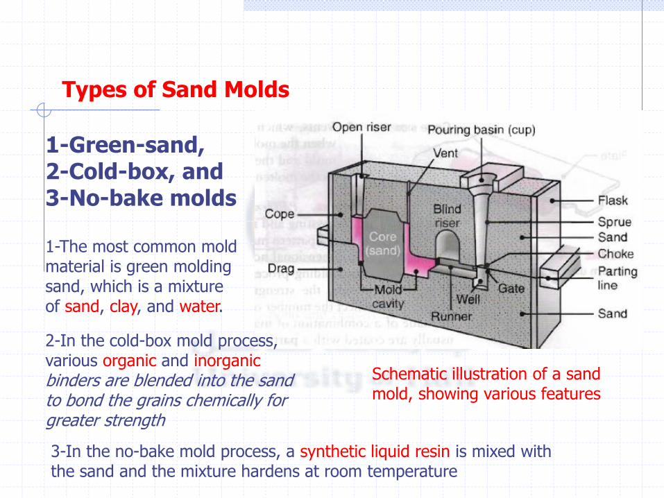
Types of Sand Molds
Schematic illustration of a sand mold, showing various features
1-Green-sand, 2-Cold-box, and 3-No-bake molds
1-The most common mold material is green molding sand, which is a mixture of sand, clay, and water.
2-In the cold-box mold process, various organic and inorganic binders are blended into the sand to bond the grains chemically for greater strength
3-In the no-bake mold process, a synthetic liquid resin is mixed with the sand and the mixture hardens at room temperature
The major features of molds in sand casting are as follows:
I. The flask, which support the mold itself. Two-piece molds consist of a cope on top and a drag on the bottom; the seam between them is the parting line. When more than two pieces are used in a sand mold, the additional parts are called cheeks. 2. A pouring basin or pouring ,cup into which the molten metal is poured. 3. A Sprue, through which the molten metal flows downward. 4. The runner system, which has channels that carry the molten metal from the Sprue to the mold cavity. Gales are the inlets into the mold cavity. S. Risers, which supply additional molten metal to the casting as it shrinks during solidification. Two types of risers-a blind riser and an open riser 6. Cores, which are inserts made from sand. They are placed in the mold to form hollow regions or otherw.ise define the interior surface of the casting. Cores also are used on the outside of the casting to form features such as lettering on the surface or deep external pockets
7. Vents, which are placed in molds to carry off gases produced when the molten metal comes into contact with the sand in the mold and the core. Vents also exhaust air from the mold cavity as the molten metal flows into the mold.
Patterns
Patterns are used to mold the sand mixture into the shape of the casting and may be made of wood, plastic, or metal. The selection of a pattern material depends on the size and shape of the casting, the dimensional accuracy and the quantity of castings required, and the molding process. Because patterns are used repeatedly to make molds, the strength and durability of the material selected for a pattern must reflect the number of castings that the mold will produce
Patterns may be made of a combination of materials to reduce wear in critical regions, and they usually are coated with a parting agent to facilitate the removal of the casting from the molds.
Patterns can be designed with a variety of features to fit specific applications and economic requirements. One-piece patterns, also called loose or solid patterns, generally are used for simpler shapes and low-quantity production; they generally are made of wood and are inexpensive. Split patterns are two piece patterns, made such that each part forms a portion of the cavity for the casting; in this way, castings with complicated shapes can be produced.
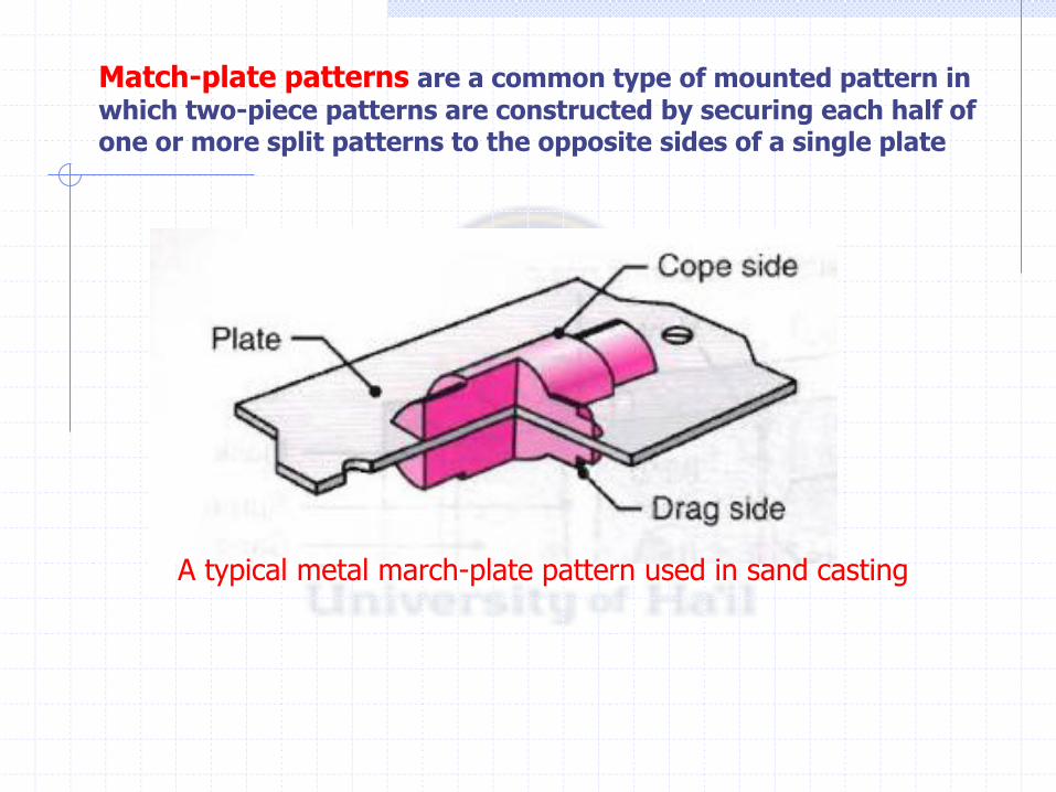
A typical metal march-plate pattern used in sand casting
Match-plate patterns are a common type of mounted pattern in
which two-piece patterns are constructed by securing each half of one or more split patterns to the opposite sides of a single plate
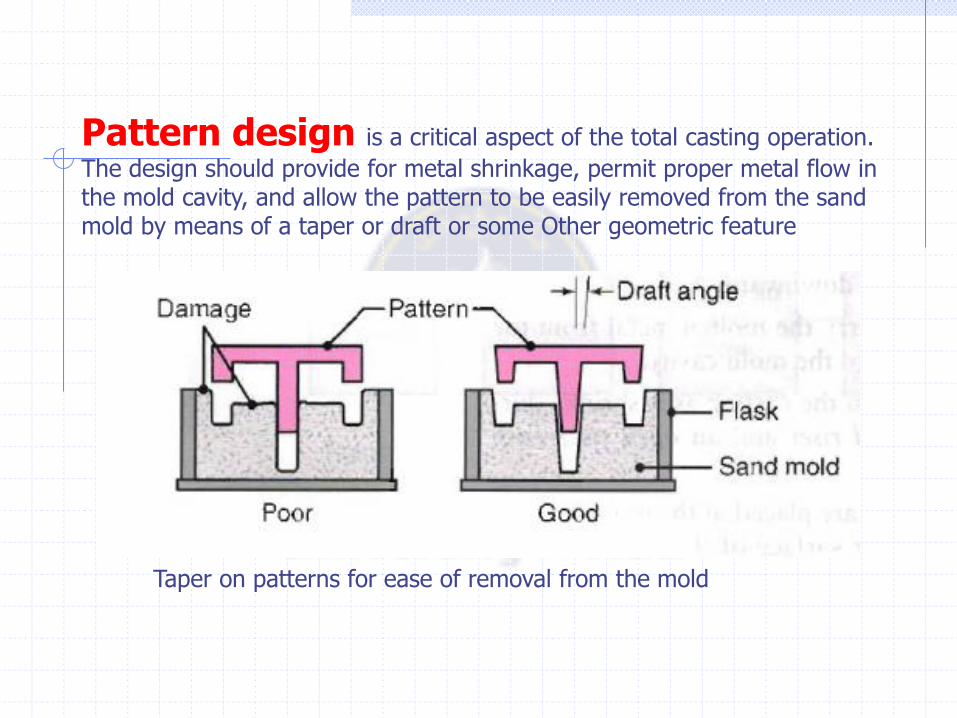
Pattern design is a critical aspect of the total casting operation.
The design should provide for metal shrinkage, permit proper metal flow in the mold cavity, and allow the pattern to be easily removed from the sand mold by means of a taper or draft or some Other geometric feature
Taper on patterns for ease of removal from the mold
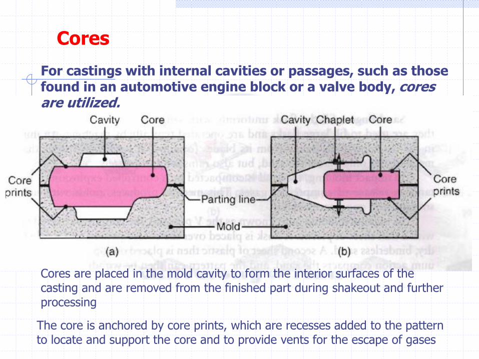
Cores
For castings with internal cavities or passages, such as those found in an automotive engine block or a valve body, cores are utilized.
Cores are placed in the mold cavity to form the interior surfaces of the casting and are removed from the finished part during shakeout and further processing
The core is anchored by core prints, which are recesses added to the pattern to locate and support the core and to provide vents for the escape of gases
Sand-molding Machines. The oldest known method of molding, which is still used for simple castings, is to compact the sand by hand hammering (tamping) or ramming it around the pattern. For most operations, however, the sand mixture is compacted around the pattern by molding machines. These machines eliminate arduous labor, offer high-quality casting by improving the application and distribution of forces, manipulate the mold in a carefully controlled manner, and increase production rate. In vertical f1askless molding, the halves of the pattern form a vertical chamber wall against which sand is blown and compacted
Sand-molding Machines
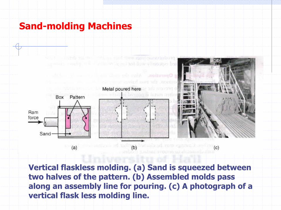
Vertical flaskless molding. (a) Sand is squeezed between two halves of the pattern. (b) Assembled molds pass along an assembly line for pouring. (c) A photograph of a vertical flask less molding line.
Sand-molding Machines
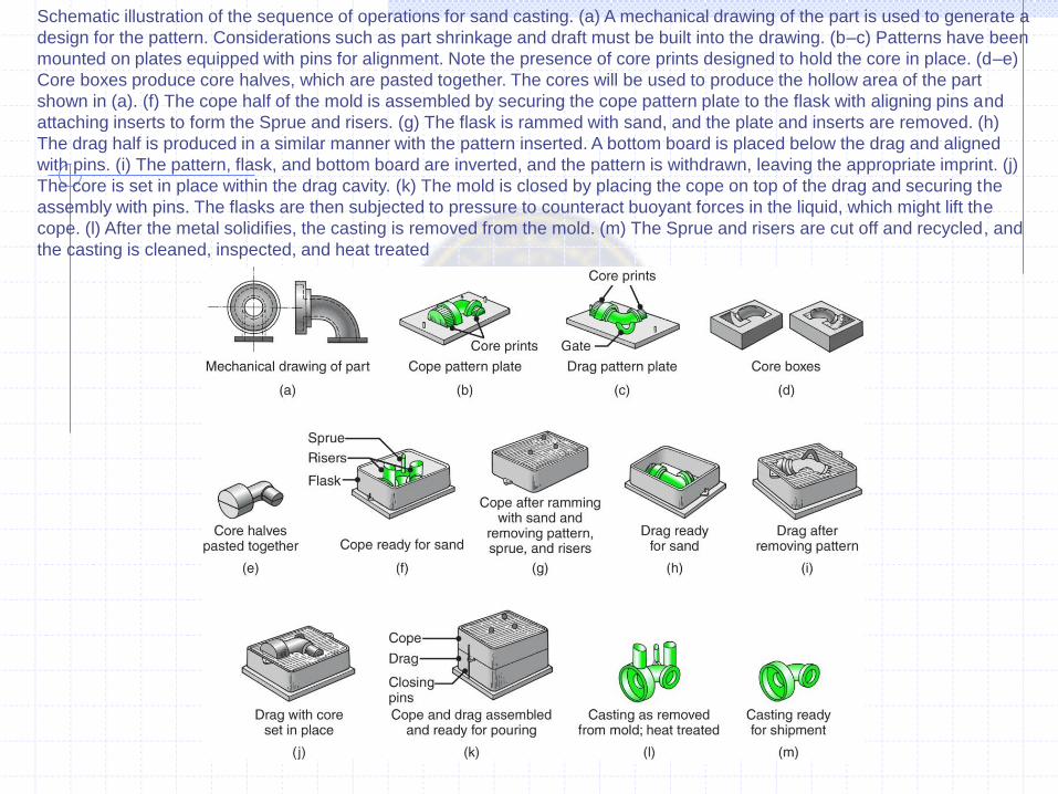
Schematic illustration of the sequence of operations for sand casting. (a) A mechanical drawing of the part is used to generate a
design for the pattern. Considerations such as part shrinkage and draft must be built into the drawing. (b–c) Patterns have been
mounted on plates equipped with pins for alignment. Note the presence of core prints designed to hold the core in place. (d–e)
Core boxes produce core halves, which are pasted together. The cores will be used to produce the hollow area of the part
shown in (a). (f) The cope half of the mold is assembled by securing the cope pattern plate to the flask with aligning pins and
attaching inserts to form the Sprue and risers. (g) The flask is rammed with sand, and the plate and inserts are removed. (h)
The drag half is produced in a similar manner with the pattern inserted. A bottom board is placed below the drag and aligned
with pins. (i) The pattern, flask, and bottom board are inverted, and the pattern is withdrawn, leaving the appropriate imprint. (j)
The core is set in place within the drag cavity. (k) The mold is closed by placing the cope on top of the drag and securing the
assembly with pins. The flasks are then subjected to pressure to counteract buoyant forces in the liquid, which might lift the
cope. (l) After the metal solidifies, the casting is removed from the mold. (m) The Sprue and risers are cut off and recycled, and
the casting is cleaned, inspected, and heat treated
Rammed-graphite Molding. In this process, rammed graphite (Section 8.6) is used to make molds for casting reactive metals, such as titanium and zirconium. Sand cannot be used because these metals react vigorously with silica. The molds are packed like sand molds, air dried, baked at 175°C, fired at 870°C, and then stored under controlled humidity and temperature. The casting procedures are similar to those for sand molds
Rammed-graphite Molding
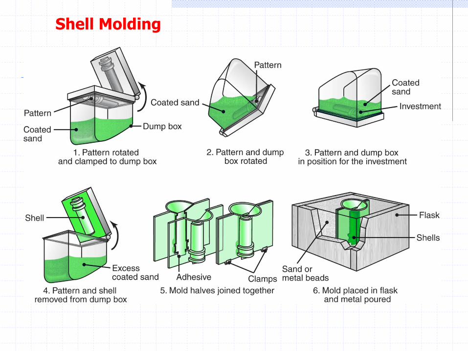
Shell Molding
Shell molding \vas first developed in the 1940s and bas grown significantly because it can produce many types of castings with close dimensional tolerances and a good surface finish at low cost
In this process, a mounted pattern made of a ferrous metal or aluminum is (a) heated to a range of 175° to 370°C, (b) coated with a parting agent (such as silicone), and (c) clamped to a box or chamber. The box contains fine sand, mixed
with 2.5 to 4 % of a thermosetting resin binder (such as phenol-formaldehyde) that coats the sand particles. Either the box is rotated upside down, or the sand mixture is blown over the pattern, allowing it to form a coating.
The assembly is then placed in an oven for a short period of time to complete the curing of the resin. In most shell-molding machines, the oven consists of a metal box with gas-fired burners that swing over the shell mold to cure it.
Shell Molding
The thickness of the shell can be determined accurately by controlling the time that the pattern is in contact with the mold. In this way, the shell can be formed with the required strength and rigidity to hold the weight of the n10lten liquid. The shells are light and thin-usually 5 to 10 mm-and consequently, their thermal characteristics are different from those for thicker molds.
Shell Molding
Shell sand has a much lower permeability than the sand used for green-sand molding, because a sand of much smaller grain size is used for shell molding. The decomposition of the shell-sand binder also produces a high volume of gas. Consequently, unless the molds are vented properly, napped air and gas can cause serious problems in the shell molding of ferrous castings. The high quality of the finished casting can reduce cleaning, machining, and other finishing costs significantly. Complex shapes can be produced with less labor, and the process can be automated fairly easily.
Plaster-mold Casting
This process, and the ceramic-mold and investment casting processes are known as precision casting, because of the high dimensional accuracy and good surface finish obtained
Typical parts made are lock components, gears, valves, fittings, tooling, and ornaments. The castings usually weigh less than 10 kg and are typically in the range of 125 to 250 g, although parts as light as 1 g have been made.
In the plaster-molding process, the mold is made of plaster of Paris (gypsum or calcium sulfate) with the addition of talc and silica flour to improve strength and to control the time required for the plaster to set. These components are mixed with water, and the resulting slurry is poured over the pattern. After the plaster sets (usually within 15 minutes), it is removed, and the mold is dried at a temperature range of 120° to 260°C. Higher drying temperatures may be used, depending on the type of plaster. The mold halves are assembled to form the mold cavity and are preheated to about 120°C. The molten metal is then poured into the mold.
Patterns for plaster molding generally are made of materials such as aluminum alloys, thermosetting plastics, brass, or zinc alloys
Plaster-mold Casting
Since there is a limit to the maximum temperature that the plaster mold can withstand (generally about 1200°C), The castings have a good surface finish with fine derails. Because plaster molds have lower thermal conductivity than other mold materials, the castings cool slowly, and thus a more uniform grain structure is obtained with less warpage.
Ceramic-mold Casting
The ceramic-mold casting process (also called cope-and-drag investment casting) is similar to the plaster-mold process, except that it uses refractory mold materials suitable for high-temperature applications.
Typical parts Ina de are impellers, cutters for machining operations, dies for metal working, and molds for making plastic and rubber components. Parts 'Neighing as much as 700 kg have been cast by this process.
The slurry is a mixture of fine-grained zircon (ZrSi04), aluminum oxide, and fused silica, which are mixed with bonding agents and poured over the pattern, which has been placed in a flask
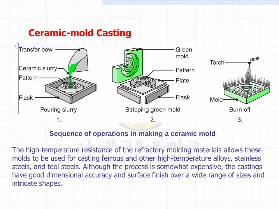
Sequence of operations in making a ceramic mold
Ceramic-mold Casting
The high-temperature resistance of the refractory molding materials allows these molds to be used for casting ferrous and other high-temperature alloys, stainless steels, and tool steels. Although the process is somewhat expensive, the castings have good dimensional accuracy and surface finish over a wide range of sizes and intricate shapes.

Expendable-mold, Expendable-pattern Casting Processes
Evaporative-pattern and investment casting are sometimes referred to as expendable pattern casting processes or expendable mold-expendable pattern processes. They are unique in that a mold and a pattern must be produced for each casting, whereas the patterns in the processes described in the preceding section are reusable. Typical applications are cylinder heads, engine blocks, crankshafts, brake components, manifolds, and machine bases.
Evaporative-pattern Casting (Lost-foam Process)
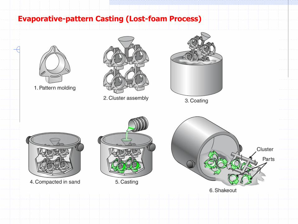
The evaporative-pattern casting process uses a polystyrene pattern, which evaporates upon contact with molten metal to form a cavity for the casting; this process is also known as lost-foam casting and falls under the trade name full-mold process.
Evaporative-pattern Casting (Lost-foam Process)
In this process, polystyrene beads containing 5 to 8% pentane (a volatile hydrocarbon) are placed in a preheated die that is usually made of aluminum. The polystyrene expands and takes the shape of the die cavity. Additional heat is applied to fuse and bond the beads together. The die is then cooled and opened, and the polystyrene pattern is removed. Complex patterns also may be made by bonding various individual pattern sections using hot-melt adhesive
The evaporative-pattern process has a number of advantages over other casting methods: The process is relatively simple because there are no parting lines, cores, or riser systems. Hence, it has design flexibility. Inexpensive flasks are satisfactory for the process. Polystyrene is inexpensive and can be processed easily into patterns having complex shapes, various sizes, and fine surface detail. The casting requires minimal finishing and cleaning operations. The process can be automated and is economical for long production runs. However, major factors are the cost to produce the die used for expanding the polystyrene beads to make the pattern and the need for two sets of tooling.
Evaporative-pattern Casting (Lost-foam Process)
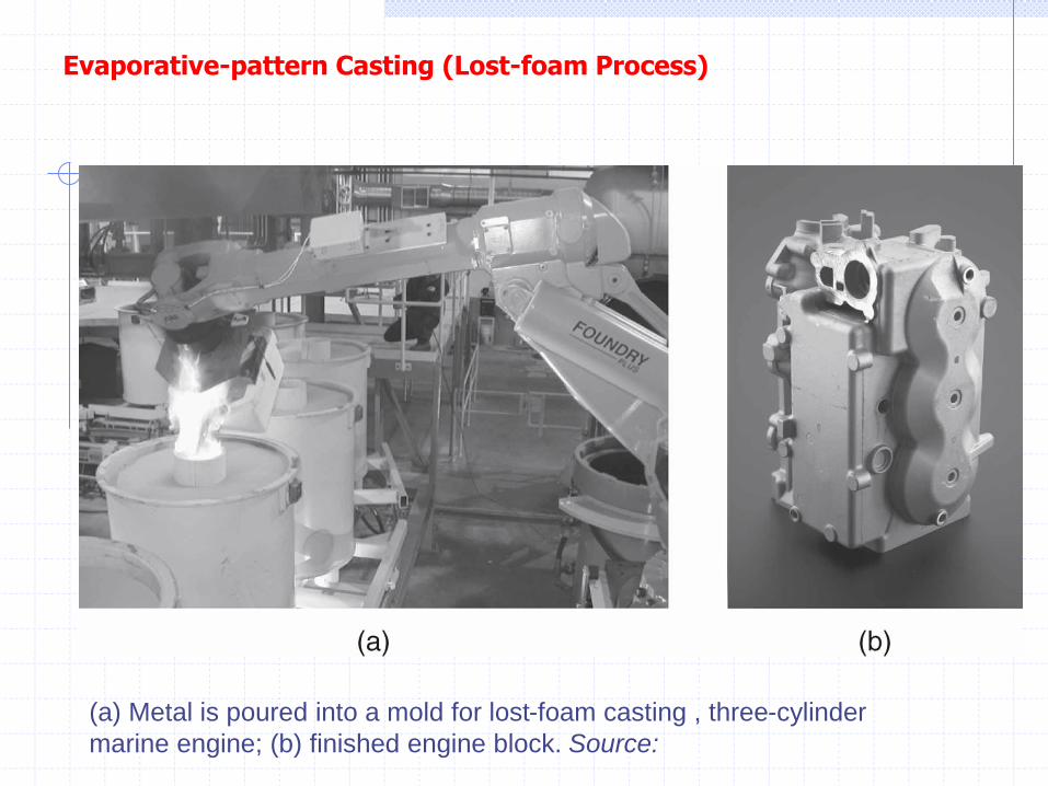
(a) Metal is poured into a mold for lost-foam casting , three-cylinder
marine engine; (b) finished engine block. Source:
Evaporative-pattern Casting (Lost-foam Process)
Investment Casting
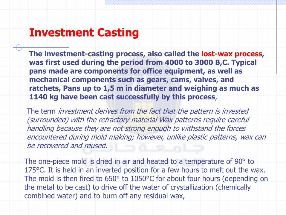
The investment-casting process, also called the lost-wax process, was first used during the period from 4000 to 3000 B,C. Typical pans made are components for office equipment, as well as mechanical components such as gears, cams, valves, and ratchets, Pans up to 1,5 m in diameter and weighing as much as 1140 kg have been cast successfully by this process,
The term investment derives from the fact that the pattern is invested (surrounded) with the refractory material Wax patterns require careful handling because they are not strong enough to withstand the forces encountered during mold making; however, unlike plastic patterns, wax can be recovered and reused.
The one-piece mold is dried in air and heated to a temperature of 90° to 175°C. It is held in an inverted position for a few hours to melt out the wax. The mold is then fired to 650° to 1050°C for about four hours (depending on the metal to be cast) to drive off the water of crystallization (chemically combined water) and to burn off any residual wax,
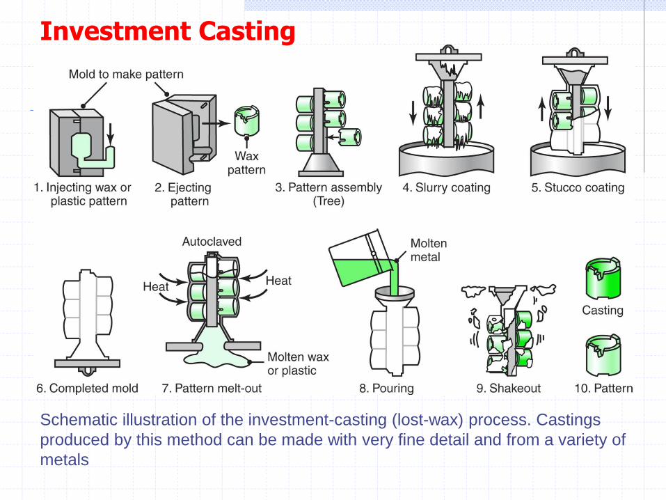
Schematic illustration of the investment-casting (lost-wax) process. Castings
produced by this method can be made with very fine detail and from a variety of
metals
Investment Casting
The process is capable of producing intricate shapes, with parts weighing from 1 g to 35 kg, from a wide variety of ferrous and nonferrous metals and alloys. Recent advances include the casting of titanium aircraft-engine and structural airframe components with wall thicknesses on the order of 1.5 mm, thus competing with previously used sheet-metal structures.
Ceramic-shell Investment Casting. A variation of the investment-casting process is ceramic-shell casting. It uses the same type of wax or plastic pattern, which is dipped first in ethyl silicate gel and subsequently into a fluidized bed of fine-grained fused silica or zircon flour. The pattern is then dipped into coarser grained silica to build up additional coatings and develop a proper thickness so that the pattern can withstand the thermal shock due to pouring.
Investment Casting
Permanent-mold Casting Processes
In permanent-mold casting (also called hard-mold casting), two halves of a mold are made from materials with high resistance to erosion and thermal fatigue, such as cast iron, steel, bronze, graphite, or refractory metal alloys.
Typical parts made are automobile pistons, cylinder heads, connecting rods, gear blanks for appliances, and kitchenware. Parts that can be made economically generally weigh less than 25 kg, although special castings weighing a few hundred kilograms have been made using this process.
The mold cavity and gating system are machined into the mold and thus become an integral part of it. To produce castings with internal cavities, cores made of metal or sand aggregate are placed in the mold prior to casting. Typical core materials are oil-bonded or resin-bonded sand, plaster, graphite, gray iron, low-carbon steel, and hot-work die steel Gray iron is used most commonly, particularly for large molds for aluminum and magnesium casting. Inserts also are used for various pans of the mold.
Permanent-mold Casting Processes
In order to increase the life of permanent molds, the surfaces of the mold cavity usually are coated with a refractory slurry (such as sodium silicate and clay) or sprayed with graphite every few castings. These coatings also serve as parting agents and as thermal barriers, thus controlling the rate of cooling of the casting.
Mechanical ejectors (such as pins located in various parts of the mold) may be required for the removal of complex castings; ejectors usually leave small round impressions.
The molds are clamped together by mechanical means and heated to about 150° to 200°C to facilitate metal flow and reduce thermal damage to the dies due to high-temperature gradients.
The process is used mostly for aluminum, magnesium, and copper alloys, as well as for gray iron, because of their generally lower melting points, although steels also can be cast using graphite or heat-resistant metal molds
Permanent-mold casting produces castings with a good surface finish, close dimensional tolerances, uniform and good mechanical properties, and at high production rates
Although equipment costs can be high because of high die costs, labor costs are kept low through automation. The process is not economical for small production runs and is not suitable for intricate shapes, because of the difficulty in removing the casting from the mold. However, easily collapsible sand cores can be used, which are then removed from castings, leaving intricate internal cavities. This process then is called semi-permanent-mold casting.
Permanent-mold Casting Processes
Die Casting
The European term for this process is pressure die casting and should not be confused with pressure casting
Typical pans made by die casting are housings, business-machine and appliance components, hand-tool components, and toys.
The weight of most castings ranges from less than 90 g to about 25 kg. Equipment costs, particularly the cost of dies, are somewhat high, but labor Costs are generally low, because the process is semi-or fully automated. Die casting is economical for large production runs.
In the die-casting process, molten metal is forced into the die cavity at pressures ranging from 0.7 to 700 MPa.
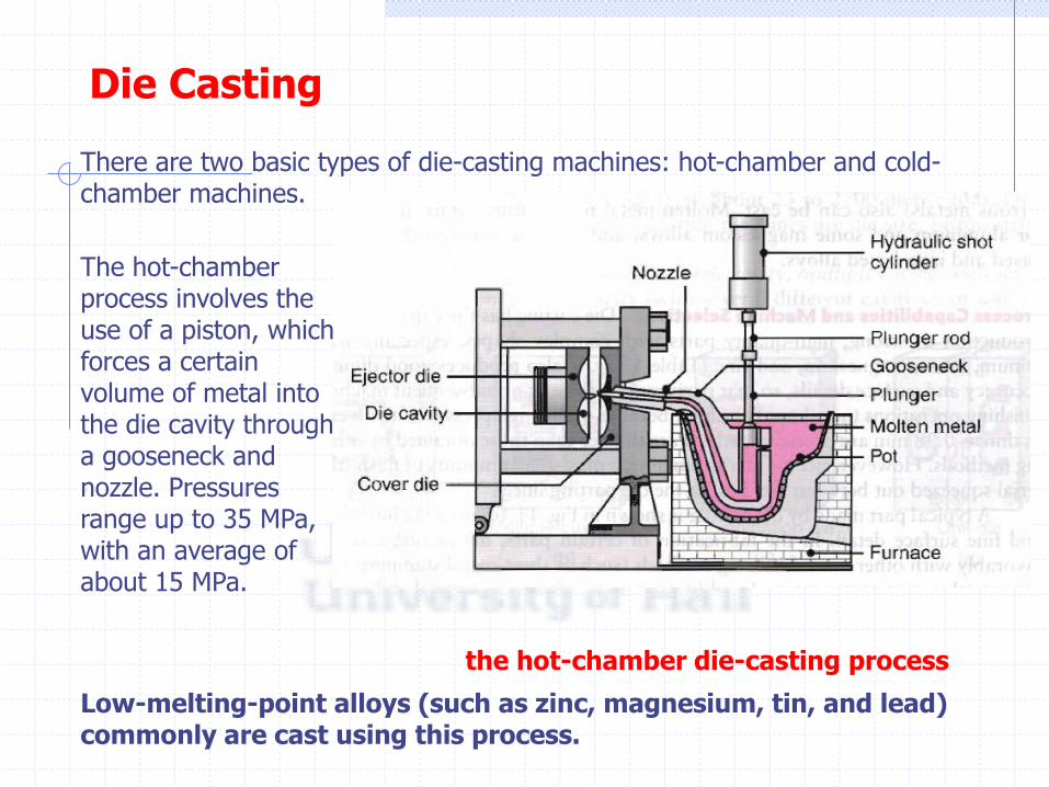
the hot-chamber die-casting process
There are two basic types of die-casting machines: hot-chamber and cold-chamber machines.
Die Casting
The hot-chamber process involves the use of a piston, which forces a certain volume of metal into the die cavity through a gooseneck and nozzle. Pressures range up to 35 MPa, with an average of about 15 MPa.
Low-melting-point alloys (such as zinc, magnesium, tin, and lead) commonly are cast using this process.
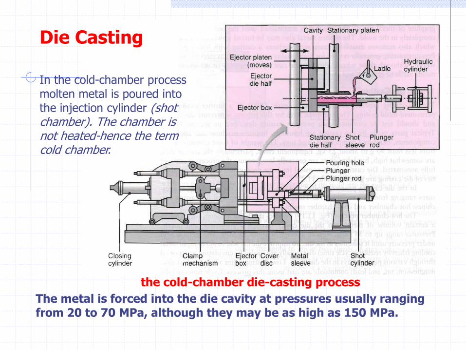
the cold-chamber die-casting process
Die Casting
In the cold-chamber process molten metal is poured into the injection cylinder (shot chamber). The chamber is not heated-hence the term cold chamber.
The metal is forced into the die cavity at pressures usually ranging from 20 to 70 MPa, although they may be as high as 150 MPa.
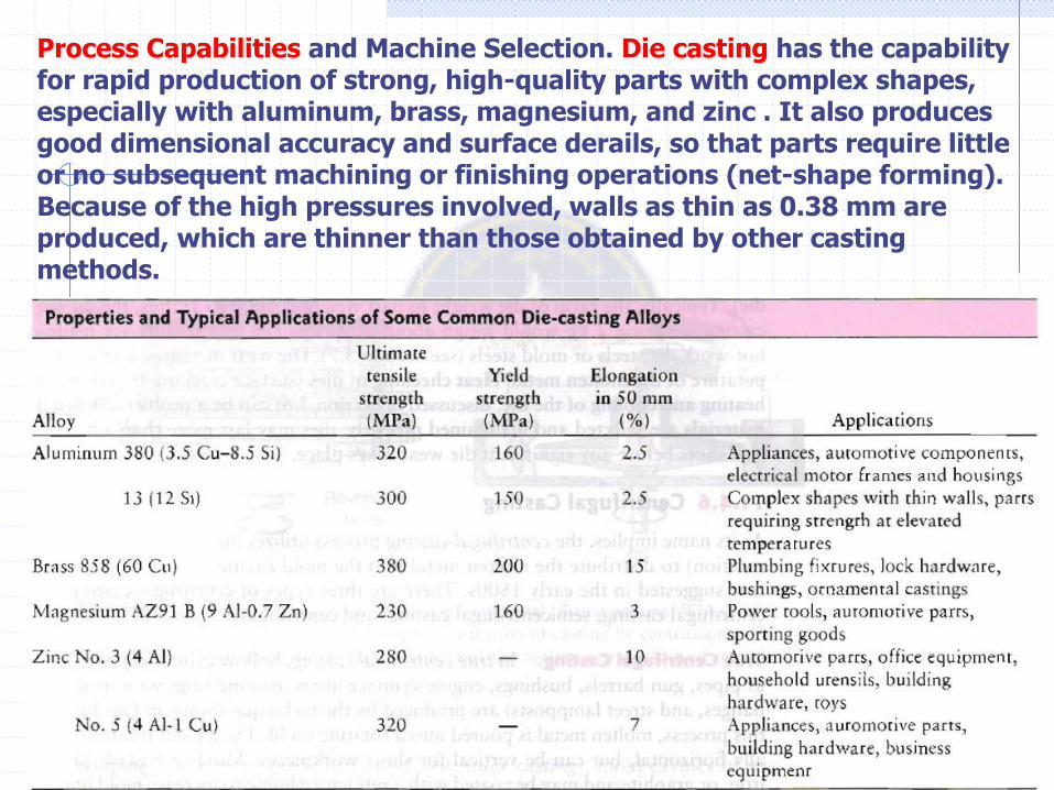
Process Capabilities and Machine Selection. Die casting has the capability for rapid production of strong, high-quality parts with complex shapes, especially with aluminum, brass, magnesium, and zinc . It also produces good dimensional accuracy and surface derails, so that parts require little or no subsequent machining or finishing operations (net-shape forming). Because of the high pressures involved, walls as thin as 0.38 mm are produced, which are thinner than those obtained by other casting methods.
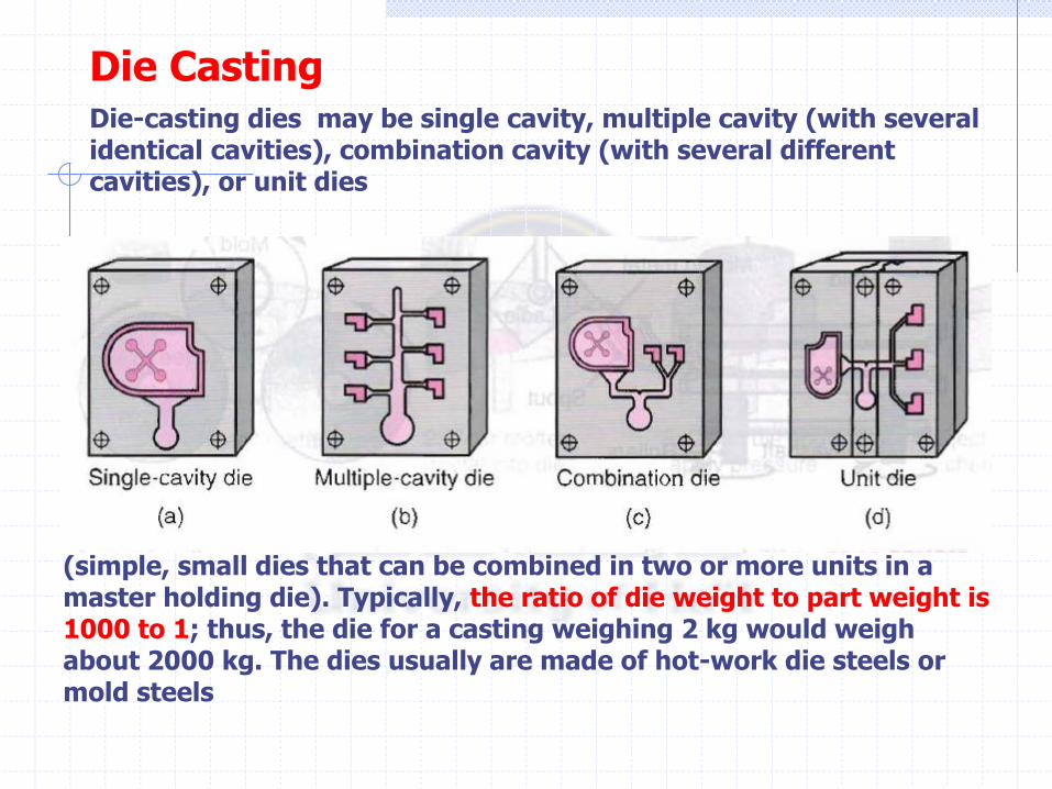
Die-casting dies may be single cavity, multiple cavity (with several identical cavities), combination cavity (with several different cavities), or unit dies
(simple, small dies that can be combined in two or more units in a master holding die). Typically, the ratio of die weight to part weight is 1000 to 1; thus, the die for a casting weighing 2 kg would weigh about 2000 kg. The dies usually are made of hot-work die steels or mold steels
Die Casting
Centrifugal Casting
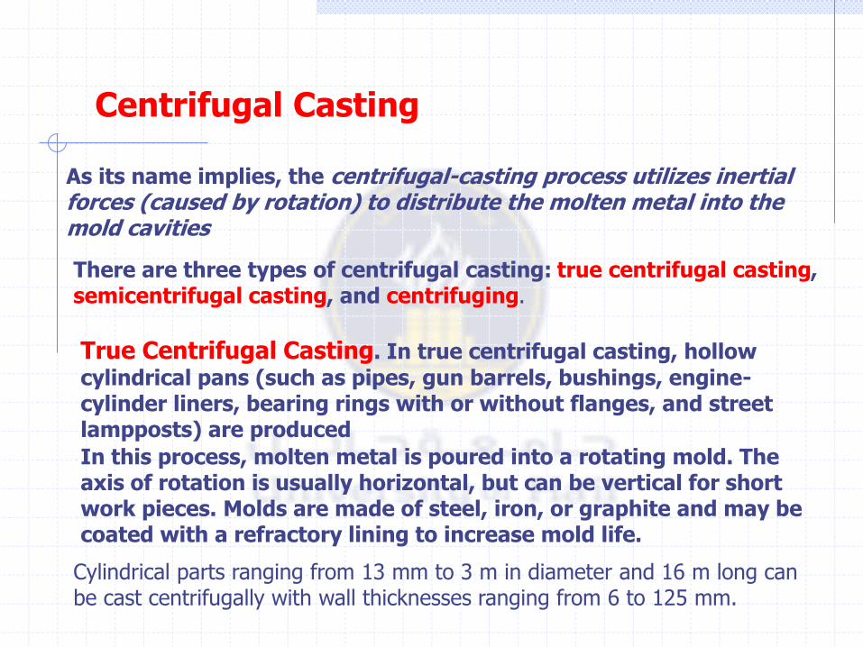
As its name implies, the centrifugal-casting process utilizes inertial forces (caused by rotation) to distribute the molten metal into the mold cavities
There are three types of centrifugal casting: true centrifugal casting, semicentrifugal casting, and centrifuging.
True Centrifugal Casting. In true centrifugal casting, hollow
cylindrical pans (such as pipes, gun barrels, bushings, engine-cylinder liners, bearing rings with or without flanges, and street lampposts) are produced
In this process, molten metal is poured into a rotating mold. The axis of rotation is usually horizontal, but can be vertical for short work pieces. Molds are made of steel, iron, or graphite and may be coated with a refractory lining to increase mold life.
Cylindrical parts ranging from 13 mm to 3 m in diameter and 16 m long can be cast centrifugally with wall thicknesses ranging from 6 to 125 mm.
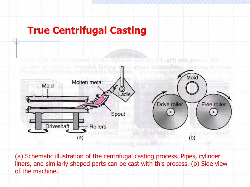
True Centrifugal Casting
(a) Schematic illustration of the centrifugal casting process. Pipes, cylinder liners, and similarly shaped parts can be cast with this process. (b) Side view of the machine.
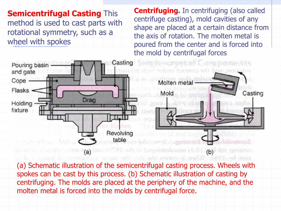
(a) Schematic illustration of the semicentrifugal casting process. Wheels with spokes can be cast by this process. (b) Schematic illustration of casting by centrifuging. The molds are placed at the periphery of the machine, and the molten metal is forced into the molds by centrifugal force.
Semicentrifugal Casting This method is used to cast parts with rotational symmetry, such as a wheel with spokes
Centrifuging. In centrifuging (also called centrifuge casting), mold cavities of any shape are placed at a certain distance from the axis of rotation. The molten metal is poured from the center and is forced into the mold by centrifugal forces
Squeeze Casting and Semisolid-metal Forming
Squeeze Casting. The squeeze-casting (or liquid-metal forging) process was developed in the 1960s and involves the solidification of molten metal under high pressure . Typical products made are automotive components and mortar bodies (a short-barrelled cannon). The machinery includes a die, punch and ejector pin.
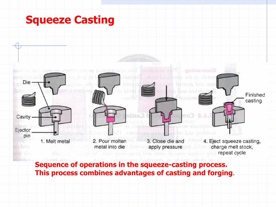
Sequence of operations in the squeeze-casting process. This process combines advantages of casting and forging.
Squeeze Casting
Rapid Solidification
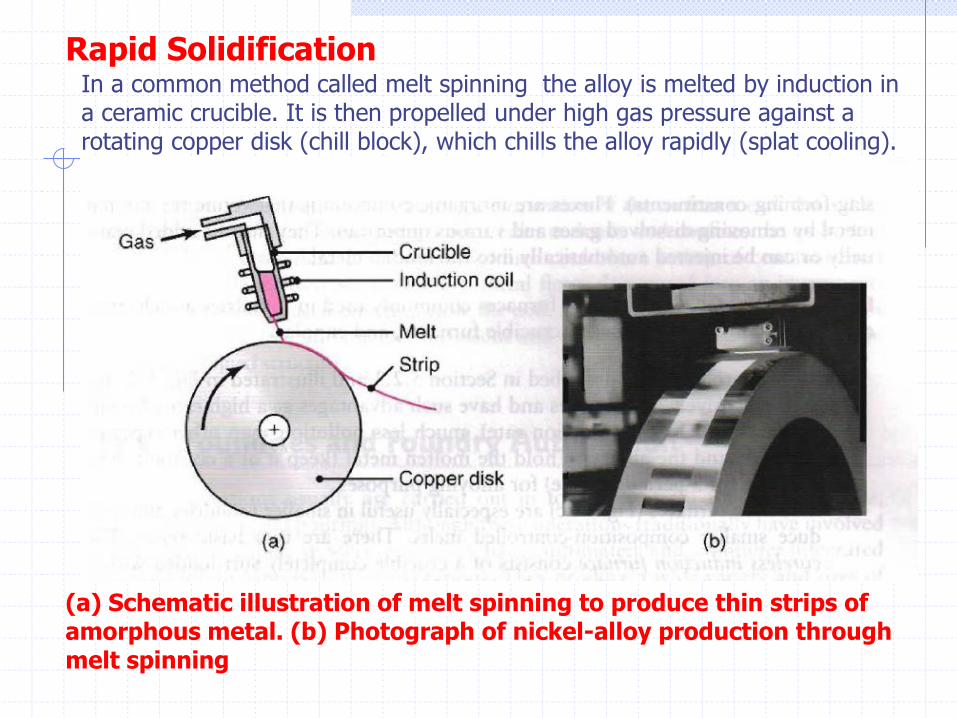
(a) Schematic illustration of melt spinning to produce thin strips of amorphous metal. (b) Photograph of nickel-alloy production through melt spinning
In a common method called melt spinning the alloy is melted by induction in a ceramic crucible. It is then propelled under high gas pressure against a rotating copper disk (chill block), which chills the alloy rapidly (splat cooling).
The properties of amorphous alloys (also known as metallic glasses) The technique for making these alloys (called rapid solidification) involves cooling the molten metal at rates as high as 106 K/s, so that it does not have sufficient time to crystallize.
Rapid Solidification
Rapid solidification results in a significant extension of solid solubility, grain refinement, and reduced micro segregation among other effects.
Inspection of Castings
The control of all casting stages-from mold preparation to the removal of castings from molds or dies-is essential to maintaining good quality.
Several methods can be used to inspect castings to determine their quality and the presence and types of any possible defects.
Castings can be inspected visually, or optically, for surface defects. Subsurface and internal defects are investigated using various nondestructive techniques
specimens are removed from various sections of a casting and tested for strength, ductility, and other mechanical properties and to determine the presence, location, and distribution of porosity and any other defects.
Pressure tightness of cast components (valves, pumps, and pipes) usually is determined by sealing the openings in the casting and pressurizing it with water, oil, or air.

Melting Practice and Furnaces
The melting practice is an important aspect of casting operations, because it has a direct bearing on the quality of castings. Furnaces are charged with melting stock, consisting of metal, alloying elements, and various other materials (such as flux and slag-forming constituents).
Fluxes are inorganic compounds that refine the molten metal by removing dissolved gases and various impurities. They may be added manually or can be injected automatically into the molten metal.
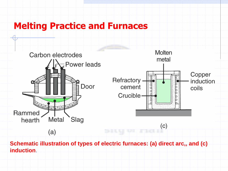
Melting Practice and Furnaces
Schematic illustration of types of electric furnaces: (a) direct arc,, and (c)
induction.
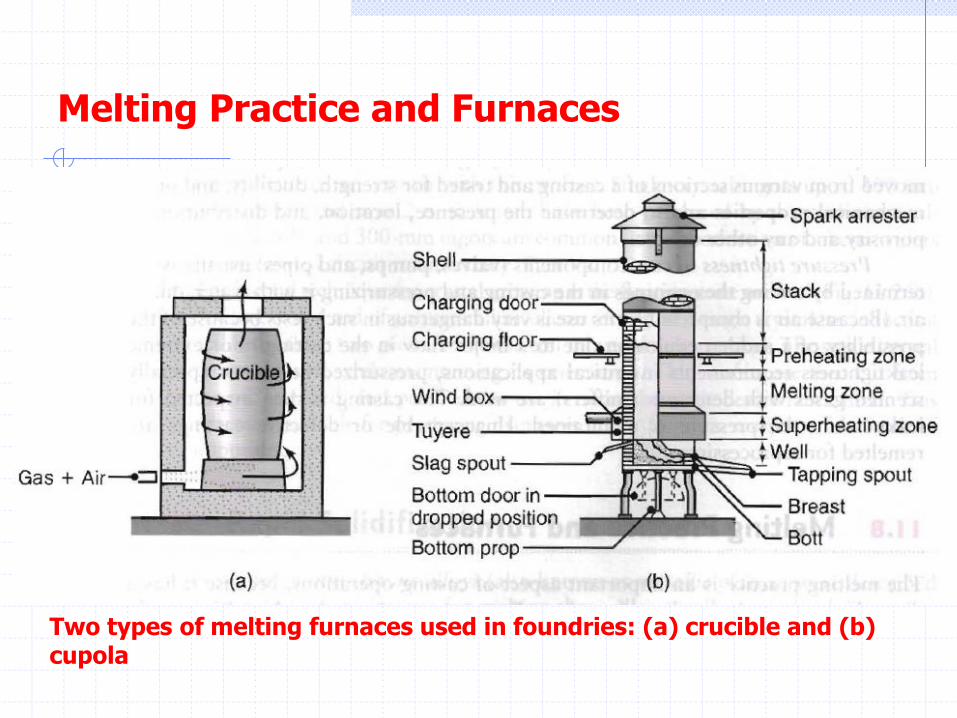
Melting Practice and Furnaces
Two types of melting furnaces used in foundries: (a) crucible and (b) cupola