metal formingmetal-forming.org/images/for-books/danchenko/danchenko-omd-engl.pdf · udc 621.771...
TRANSCRIPT
MINISTRY of EDUCATION and SCIENCE of UKRAINE
NATIONAL METALLURGY ACADEMY of UKRAINE
V. N. DANCHENKO
METAL FORMING
Dnepropetrovsk NMetAU 2007

MINISTRY of EDUCATION and SCIENCE of UKRAINE
NATIONAL METALLURGY ACADEMY of UKRAINE
V. N. DANCHENKO
METAL FORMING
The present book is recommended by the Ministry
of education and science of Ukraine as a text-book
for students of higher educational institutions
studying along direction ''Metallurgy''
Dnepropetrovsk NMetAU 2007

UDC 621.771
Danchenko V.N. Metal forming: text-book. – Dnepropetrovsk: NMetAU,
2007. – 183 p.
Данченко В.Н. Обработка металлов давлением: Учебное пособие. –
Днепропетровск: НМетАУ, 2007. – 183 с.
The fundamental of metal forming theory, the theories
of processes of rolling, forging and stamping as well as draw-ing and pressing (extrusion) have been given.
The characteristics of the shop equipment for metal forming and technology of the main metal forming methods have been given in separate sections.
The text-book is intended for students of higher educa-tional institutions, specialty "Metallurgy".
Fig. 80. Таble 3. Reference list: 3.
Приведены основы теории обработки металлов дав-лением, а также процессов: прокатки, ковки и штампов-ки, волочения, прессования.
В отдельных разделах приведены характеристика оборудования цехов обработки металлов давлением и тех-нология основных видов обработки металлов давлением.
Предназначено для студентов по направлению "Ме-таллургия".
Илл. 80. Табл. 3. Библиогр.: 3 назв.
Reviewers: G.V. Levchenko, Doctor in engineering Sciences (The State
Technical University, Dnieprodzerzhinsk)
S.M. Zhuchkov, Doctor in engineering Sciences (Iron and Steel
Institute of Ukraine Academy of Sciences)
V.P. Sokurenko, Doctor in engineering Sciences (The State
Tube and Pipe Institute)
© National metallurgy
academy of Ukraine, 2007
ISBN 996-525-716-1 © Danchenko V.N., 2007

3
CONTENT
INTRODUCTION ........................................................................................ 4 1. THE FUNDAMENTALS OF PLASTIC DEFORMATION OF
FERROUS METALS, NON-FERROUS METALS AND ALLOYS .. 5 1.1. The types of metal forming ................................................................. 5 1.2. Mechanical properties of metals ......................................................... 7 1.3. Cold metal forming ........................................................................... 10 1.4. Hot metal forming ............................................................................. 16 1.5. External (contact) friction ................................................................ 19 1.6. Stress and strain state in the processes of metal forming ................. 22 1.7. Strain resistance and plasticity during hot metal forming ................ 25 1.8. Determination of deforming stress in the processes of metal forming . 31 1.9. The main laws of plastic deformation .............................................. 33
2. THE THEORY OF METAL FORMING PROCESSES ................... 39 2.1. Lengthwise (longitudinal) rolling ..................................................... 39 2.2. Continuous rolling ............................................................................ 56 2.3. Screw rolling ..................................................................................... 61 2.4. Drawing ............................................................................................ 70 2.5. Pressing (extrusion) .......................................................................... 73 2.6. Smith (free) forging .......................................................................... 79 2.7. Hot die forging .................................................................................. 83 2.8. Sheet metal stamping ........................................................................ 87
3. PROCESSES AND EQUIPMENT OF ROLLING............................. 91 3.1. Classification of the rolling mills ..................................................... 91 3.2. Equipment of the rolling shops ......................................................... 97
4. SECTION AND SHEET MANUFACTURING ................................ 104 4.1. Rolled-products range ..................................................................... 104 4.2. The main technological operations in the rolling shops ................. 107 4.3. Cogging-billet production ............................................................... 108 4.4. Continuous casting billets manufacturing ...................................... 110 4.5. Shape and bar production ............................................................... 112 4.6. Sheet production ............................................................................. 123
5. TUBE AND PIPE MANUFACTURING ........................................... 141 5.1. Tube and pipe range ........................................................................ 141 5.2. Seamless hot rolled tubes production ............................................. 142 5.3. Cold rolling of tubes ....................................................................... 150 5.4. Production of welded tubes ............................................................ 155
6. DRAWING, PRESSING AND DIE FORGING PRODUCTION ... 160 6.1. Drawing .......................................................................................... 160 6.2. Pressing (extrusion) ........................................................................ 166 6.3. Smith forging .................................................................................. 171 6.4. Die forging ...................................................................................... 174 6.5. Sheet metal stamping ...................................................................... 177
QUESTIONS FOR EXAMINATION .................................................... 181
REFERENCE LIST ................................................................................. 183

4
INTRODUCTION
Metal forming is the final stage of metallurgical manufac-
turing permitting to produce metal ware used in national econ-
omy as the finished products or as the billet for further pro-
cessing. Metal forming is the main method of making metal
products and semi-finished products. More than 90% of smelt-
ed metal is processed by different methods of metal forming.
Plastic properties of metals are used during the process of
metal forming. That is the ability to change without damage the
shape and dimensions in hot and cold condition under the pres-
sure of machining tools. The knowledge of metal forming rules
permits to realize the forming at optimum deformation regimes
and to use the appropriate main and auxiliary equipment. The
variety of methods and kinds of metal forming permits produc-
ing the wide range of metal products with high productivity,
exact dimensions, required mechanical properties.
The development of metallurgical manufacture has result-
ed in appearance of new kinds of metal forming where the pro-
cesses of casting and hardening metal reduction are being com-
bined.
New technological processes of metal forming give the
possibility to shape the product at high strain rate, to obtain the
products with especially high mechanical properties, to reduce
the number of process stages and equipment used for it.

5
1. THE FUNDAMENTALS OF PLASTIC
DEFORMATION OF FERROUS METALS,
NON-FERROUS METALS AND ALLOYS
1.1. The types of metal forming
Rolling is the most commonly used and the most efficient
type of metal forming, which consists in deformation of metal
by means of rotating rolls (Fig. 1.1, a, b, c); 75-80% of the total
quantity of smelted metal is being processed by rolling.
a b c
d
e f
g h
Fig. 1.1. The schemes of the metal forming processes:
a – lengthwise rolling; b – cross rolling; c – helical roll-
ing (1, 2 – rolls; 3 – billet; 4 – shell; 5 – mandrel);
d – smith forging; e – closed die forging; f – drawing;
g – pressing (extrusion); h – sheet stamping
6
The long length products of constant or variable cross-
section along the product length are produced by method of
lengthwise rolling. The direction of rolls rotation promotes
pulling the billet by means of friction forces to the gap between
the rolls where the billet is reduced in thickness. It results in in-
crease of the length and the width of the billet. The rolls with
smooth surface are used for rolling plates and roll grooves
forming the required shape of strip cross section – passes – are
used for production of section bars – beams, channels, rails etc.
During the process of cross rolling the rolls are rotating in
the same direction. The billet is fed in axial direction and it re-
ceives the rotational movement contacting the rolls. The billet is
retained in rolls by special device during the process of rolling
and reducing by rolls. The sections being the bodies of revolu-
tion such as balls, gears etc. are produced by cross rolling.
The helical (skew) rolling is realized in barrel-shaped rolls
rotating in the same direction and installed with some skewness
of axes. The billet feed in axial direction receives the rotational
movement and simultaneously, due to the rolls skewness of ax-
es, the translational movement ahead. During the process of bil-
let rolling its diameter is reduced, the core of the billet be-
comes. The mandrel installed towards the billet movement di-
rection allows to obtain the hollow product – the shell from
which the tube is produced by means of the further processing.
Forging is a widely used method of metal forming. There is
a free forging (Fig. 1.1, d) and closed die forging (Fig. 1.1, e).
During the process of free forging the reduction of the forging
piece height is realized between two parallel surfaces of ham-
mer heads, and the flow of metal in the transverse direction is
not limited by the shape of the heads. The variety of the manu-
factured products shapes is achieved by the reduction of the bil-
let in different directions, using of auxiliary operations of bend-
ing, twisting, drawing, piercing etc. The billet is placed to the
cavity of one die part and under the action of another part of the
die the billet is filling the cavity taking its shape during the pro-
cess of die forging. It makes the process of the product shaping
simpler and permits to increase the efficiency of forging.

7
The drawing of the metals is used in manufacturing of small
sections and relatively long length products such as wire, rods,
tubes (Fig. 1.1, f). The pointed end of the rod is pushed through
the conical hole of the tool (drawing die), is clamped at the die
exit by clips or spooled and under the action of applied force is
drawn through the die with reduction of cross section area and
corresponding elongation. The drawing permits to obtain the
products with exact dimensions and good quality of surface.
Pressing is the method of product manufacturing by
means of metal extrusion through the die hole (Fig. 1.1, g). It is
mainly used in non-ferrous metallurgy and aviation industry
where the shaped sections are produced from such materials as
Al- and Ti-based hard-to-deform and low-plasticity alloys.
Sheet stamping is the method of metal plastic processing
in which the sheet and strip bars are used for product manufac-
turing (Fig. 1.1, h). The complex shape products with high
strength and rigidity and small mass are produced in the process
of separating, shaping and assembly operations; they are widely
used in many sectors of national economy. Sheet stamping is
the highly efficient method of metal forming and has the wide
spreading.
1.2. Mechanical properties of metals
Forces and deformations during the hot and cold metal
forming depend upon mechanical properties of processed mate-
rials, which in their turn depend upon the nature (chemical
composition, structure) of metal as well as upon the defor-
mation conditions (temperature, degree and rate of defor-
mation).
Strength, elasticity, plasticity, impact strength and hard-
ness are concerned to be the mechanical properties.
The strength of the metal is interpreted as its ability to
stand without damages applied loads at which the internal in
stresses metal do not exceed some limit value for the given

8
metal. This value is called ultimate strength or ultimate re-
sistance (ult).
The actual data about the mechanical properties of the
metals may be obtained by means of testing the standard spec-
imens according to the regulated by standards methods at room
and high temperatures. Linear stretching is one of the most
widespread methods of testing. The diagram of the stresses
conv=Р/F0 changing during the process of deformation
=l/l0100% (where conv is conventional value of stresses at
load P correlated to the initial specimen cross-section area F0;
l is the absolute elongation of specimen; l0 the initial length of
specimen) is given on Fig. 1.2.
Fig. 1.2. The diagram –
at tensile test
The proportional connection between stresses and defor-
mation according to Hook’s law = (where Е is the modulus
of elasticity) is taking place at the 0-1 area. The stress at the
point 1 is called the proportional limit and designated as prop.
At the area 1-2 the deformations are elastic (that is, they disap-
pear after removing the load), but the connection between the
stresses and deformations becomes nonlinear. The stress in the
point 2 is called elastic limit and designated el. After point 2 the
plastic (residual) deformation is beginning and in point 3 runs up

9
to 0.2%. The stress corresponding to the position of point 3 is
called conventional yield strength and designated as 0.2.
The further deformation at the area 3-4 is accompanied by in-
creasing of conventional stress (the effect of metal hardening
during the process of deformation). If to relieve the load at any
point A in the area 3-4, the total deformation А will be de-
creased for value el and the beginning of the diagram will
move to point О'. During the next loading the limit of material
plasticity is increasing and the plastic deformation begins only
in the point А'. The variable value of stresses in the area 3-4 is
called yield stresses yield.
On reaching the maximum of conventional stresses in the
point 4 the specimen deformation becomes irregular: the local
reduction of cross section (the neck) is forming, conventional
stresses are reduced and the destruction is taking place in the
point 5. The value of conventional stresses corresponding to the
point 5 on the diagram is called the stress of breaking sep.
If to take into account the change of cross section area of
specimen during the process of stretching, which becomes con-
siderable by the moment of neck formation, then the view of
diagram will be changed (is shown by dotted line), the harden-
ing of metal (the increase of stresses real=Р/Freal) is going on
up to the moment of destruction.
In addition to the specimen strength indexes metal plastici-
ty indexes are also determined during tensile test. Plasticity is
the property of metal to be deformed without damage. Plasticity
index is the maximum obtainable value of relative deformation
before destruction. During the tensile test the relative elongation
is considered to be the index of plasticity:
%100Δ
0
l
l,
where l is the maximum value of absolute residual elongation.
The shape of tested specimen influences the value of this in-
dex, ratio of the specimen length l0-to-diameter d0. The specimens
with the ratio l0/d0=5 or l0/d0=10 are used. The indexes of relative
elongation for this tests are indicated as 5 or 10.

10
The plasticity properties of metals are evaluated by the
index of relative reduction:
%1000
10
F
FF,
where F1 is the area of cross section of the specimen at the place of fracture.
Besides tensile tests mechanical properties of metals may be determined also by means of test for setting, twisting, impact buckling as well as by different technological probes.
The index of impact elasticity KCU is determined by the value of work A expended for fracture of the standard specimen correlated to the area F of the specimen cross section at the
place of the cut: KCU=A/F, Jcm-2. The test for determination of impact elasticity is conduct-
ed on pendulum ram engines. The specimen is laid easily on two supports. The expended work for destruction of a specimen is determined according with the change of potential energy of the ram engine mass at the initial position and in the fixed posi-tion after deformation.
Resistance to indentation into surface of different kinds of instruments is understood as metal hardness. There are different methods for hardness test in accordance to the used instru-ments. At the hardness test after Brinell HB, Rockwell HR and Vickers HV the hardness is determined by the depth of intru-sion of tempered steel or tungsten ball, diamond cone or pyra-mid into the tested material. The hardness according to Shore HSD is determined at falling of steel head with diamond on the end in standard conditions and is measured in conventional units according to the height of the head rebound. This method is convenient for application in production conditions.
1.3. Cold metal forming
Plasticity deformation mechanism

11
The metals have the crystalline structure. As usual metals
consist of a great number of crystals of different shape and siz-
es, which are called grains. Grains are combined between them-
selves as a single whole by the forces of inter atomic bond.
Metal have the arrangement ordered and form lattice (Fig. 1.3).
a b c
Fig. 1.3. Types of some metals' lattices:
a – face-centered cubic lattice;
b – body-centered cubic lattice;
c – hexagonal cubic lattice
The definite orientation of crystallographic axes causes
anisotropy (distinction at different directions) of physical prop-
erties of crystals. But in case of disordered arrangement of
grains in the metal volume, the physical properties at different
directions are averaged and the body becomes as it was iso-
tropic (quasi-isotropic).
Under the action of tangential stresses the shear defor-
mation in the cells of lattice is taking place. In case if the value
of atoms displacement of one layer relatively the other one ex-
ceeds the half of the inter atomic distance, the transition of at-
oms to the new position of stable equilibrium is taking place,
that is the transition of atoms becomes irreversible, the metal
deformation will be residual – plastic. This mechanism of plas-
tic deformation is called slipping (Fig. 1.4, a).
Sliding represents the shear of one part of crystal relative-
ly to another in some planes. As usual the slipping is going on
simultaneously in many parallel planes, in which connection
the number of these planes is increasing as soon as the deform-

12
ing force is increasing. As the result, the numerous slip bands
are formed (as the superfine layers). The sliding planes have
definite crystallographic directions. The sliding planes are those
Fig. 1.4. Mechanisms of plastic deformation:
a – slipping; b – twinning
with the greatest density of atoms distribution and the sliding is
going on along the directions where the distance between atoms
has the minimum value. The number of planes and directions of
sliding depends upon the type of lattice and in body-centered
lattice amounts to 14, in face-centered lattice – 4, in hexagonal
lattice – 2.
The process of sliding is greatly facilitated due to the suc-
cessive shear of atoms in the sliding plane in case of presence
of crystal lattice imperfection in real metals. Considerably less-
er stresses are required for dislocation displacement in the plane
of sliding in comparison the simultaneous shear of atoms along
the whole plane. The distortion of planes of sliding is taking
place during the process of plastic deformation which makes
the deformation along these directions more difficult, the new
shears are originating at the new directions. The deformation is
stopped when all free directions for shears are used.
The second mechanism of plastic deformation is twinning,
which presents the shear of the crystal part with formation of
mirroring of one part of crystal regarding the other (Fig. 1.4, b).

13
The twinning can be observed more often at lower temperatures
as well as at load impacts.
The mechanism of plastic deformation of real metal (poly-
crystal) is much more complicated than of separate crystal. The
grains of poly-crystal differ between themselves as to the shape
and sizes, may be differently oriented as to the deforming load,
may have different mechanical properties. During the process
of crystallization the intercrystalline layers are formed, which
differ from the main metal as to composition, structure and are
enriched by admixtures. Two types of poly-crystal deformation
are distinguished: transcrystalline (by grain) and inter-
crystalline (by grain boundaries). The first is passing by means
of sliding and twinning, the second by means of turning and
displacement of some grains relatively to another one. The both
types of deformation are passing simultaneously.
Since the grains have different orientation of the planes
of slipping, the plastic deformation is starting not in all grains
at the same time. At first the grains are forming, which planes
of sliding coincide with the directions of maximum shear
stress action (Fig. 1.5, a, grains 1, 2, 3, 4). The rest of the
grains are turning during the process of deformation, their
planes of sliding are orienting more favorably to the direction
of maximum shear stress action, and they are also subjected
to deformation (Fig. 1.5, b). As the result the changing of the
grains form is going on: they are stretching out at the direc-
tion of the most intensive flow of metal (Fig. 1.5, c). Simulta-
neously with grains form change, the turning of sliding planes
with formation of similar crystallographic orientation of
grains of deformed structure is taking place. This structure of
cold deformed metal is called texture and causes anisotropy
of properties in poly-crystal.

14
Fig. 1.5. Scheme of successive development
of polycrystal plastic deformation
Metal hardening
Plastic deformation of metal causes not only the change of
shape and sizes of billet during the process of cold plastic work-
ing (stamping, drawing, thin sheet rolling), but also the change
of physical-mechanical as well as chemical properties of the
metal. The strength characteristics are increasing with increas-
ing of deformation degree and plastic characteristics are de-
creasing (Fig. 1.6). Simultaneously the electric resistance is in-
creasing and corrosion resistance and thermal conductivity are
decreasing; magnetic conductivity is decreasing and coercive
force is increasing. As can be seen from Fig. 1.6, the difference
between the yield strength and ul-
timate strength is decreasing with
the increasing of deformation de-
gree, and at 70-90% deformation
the yield strength almost coincides
with ultimate strength.
The aggregate of phenomena
connected with change of mechan-
ical and physical-chemical proper-
ties during the process of plastic
deformation is called hardening or
work-hardening of metal.
The physical nature of hard-
ening is interpreted by the disloca-
tion theory. The dislocation
movement is not going freely in
Fig. 1.6. Influence of
degree of deformation
on mechanical properties
of the steel 08кп

15
real metals .There are obstacles on the way of dislocations such
as interstitial atoms, precipitates of other phases, grain bounda-
ries, intersection of sliding planes etc. The field of stresses
around the dislocations is resiliently interacting with the field
around the obstacles, and sliding in the given plane is short-
stopping. To continue the deformation it is necessary to in-
crease the deforming stress and the sliding will go along the
less favorably oriented crystal planes. The interaction of lattice
defects brings to formation of micro cracks, which are decreas-
ing the plasticity of the metal.
The hardening during the deformation permits to regulate
the final properties of metal products within the broad limits. It
is possible to increase the strength of the metal 2-3 times by
means of cold plastic working. On the other hand the decrease
of plastic properties of the metal limits the possibility of con-
ducting the further plastic forming and generates the need of
metal heat treatment for renewing the plastic properties and re-
duction of strain resistance.
The determination of yield stresses during
the process of cold metal forming
It is necessary to use the experimental data about the me-
chanical characteristics of different metals obtained after differ-
ent kinds of tests for accomplishing the engineering calcula-
tions of deforming forces during the processes of cold metal
forming. These data are presented in standards for different
steel grades and alloys with indication of delivery conditions
and the type of heat treatment. The considerable change of me-
chanical properties takes place during the process of defor-
mation. The metal hardening comes with the increase of defor-
mation rate. For determination of energy-power characteristics
at cold deformation of metals the data are needed to be present-
ed about the mechanical properties of metals in non-cold-
hardened condition (at 20ºC) and in dependence on the defor-
mation rate . These data for different metals are given in refer-
ence books in the form of diagrams of dependence of conven-

16
tional yield strength on total deformation rate (in the form of
hardening curves). Besides that, for many steel grades and al-
loys the empirical formulas are given for determination of con-
ventional yield strength as follows:
yield = yield0 + a b,
where yield0 – yield strength of non-deformed (annealed) metal;
a, b – coefficient and index of deformation rate , %.
For instance, for steel grade 45: yield=343+850.48 (МPа).
For performing the calculations of metal forming process-
es the necessity of determination of the mean value of yield
strength is arising within the specified interval of deformation
from: init (initial value of deformation rate) up to fin (the final
value of deformation rate). Medium-integrated value of yield
strength within this interval can be determined as follows:
.1
d
initfin
1init
1fin
0Тinitfin
avyield
fin
init
bbt
b
a
The value of the yield strength at desired initial defor-
mation rate yield init can be determined as well as desired finite
degree of deformation yield fin according to the approximation
formulas:
for annealed metal and at small deformations:
yield av=(yield init+2yield fin)/3;
for hardened metal:
yield av=(yield init+yield fin)/2.
The influence of the deformation rate on the yield strength
is not taken into account during the process of cold defor-
mation. But the very high deformation rates due to the evident
metal heating yield stress of the work metal is rather decreasing
during the heat evolution.

17
1.4. Hot metal forming
The deformation is conducted in heated state for decreas-ing the strain resistance and increasing the plasticity of the worked metal. The rise in temperature no higher than (0.3-0.4)Тf (Тf – the metal fusion temperature in absolute scale, ºK) doesn’t bring the structure changes to the metal, but the acceleration of diffusion processes contributes to the healing of structure de-fects and drop of inner stresses in metal. At temperatures of heating higher than 0.4Тf the process of grain recovery takes place in the metal. The nucleuses of the new grains, which are the centers of grain recovery, are being formed at the bounda-ries of deformed grains. The new grains are growing due to the solution and absorption of deformed grains. The rate of the pro-cess of grain recovery depends upon the temperature of metal heating: the higher the metal temperature is, the faster the pro-cess of the grain recover is going on. The processes of structure deformation and metal hardening connected with deformation are going on simultaneously during the process of hot metal forming as well as the process of formation of new structure as the result of grain recovery following by the weakening.
The temperature of metal heating is taken higher than
0.7Тf for the process of grain recovery to be over completely
during the metal forming or partially with completion after de-
formation finishing. This kind of metal forming is called hot
forming. Within the temperature interval (0.3-0.7)Тf the metal
forming is called the incomplete hot or incomplete cold form-
ing. The mechanisms of plastic deformation are the same dur-
ing the hot forming and cold forming: sliding and twinning
within the grains, mutual displacement and turning of grains. At
high temperatures the additional mechanisms such as amor-
phous-diffusion, inter-grain recrystallization and inter-phase so-
lution-precipitation mechanisms, which play the secondary part
during the process of forming enter in action.
The new grains, which have been formed after grain re-
covery are arbitrary oriented in space, they have approximately
equal dimensions along all directions what causes the isotropy
of mechanical properties of the hot deformed metal. The struc-

18
ture of hot deformed metal with equi-axial grains doesn’t allow
to determine the direction of the main deformations during the
forming. The tracks of admixtures may be however remained in
the structure located at the boundaries of grains of cold de-
formed metal before the hot forming. It causes the possibility of
getting fibrous structure after hot deformation as well.
The size of grains received after grain recovery depends
upon metal deformation rate conducted before grain recovery.
The inner energy reserve of the metal doesn’t permit to form
great quantities of grain recovery centers at small deformation
rates, which are called as critical. The quantity of new grains in
grain recovered structure will be moderate, and the obtained
structure will be coarse-grain one. This structure has the low
mechanical properties and its formation is undesirable. The
quantity of new formed grains is increasing with the increas-
ing of deformation rate and the structure of the metal be-
comes fine-grained.
The temperature interval within which the hot forming is
possible to conduct depends upon carbon content in steel and is
determined in dependence on the state diagram for different
metals.
The diagram Fe-C section is shown on Fig. 1.7 and corre-
sponds to the content of carbon in steels. The temperature range
within which the forming of steels with different carbon content
is possible is shown by shading.
The upper limit of temperature range tu.l. is determined by
the danger of overheating or over burning the metal. The pro-
cess of collecting recrystallization with formation of very
coarse-grained structure may take place in the metal in the fur-
nace area at high temperatures and long term ageing of metal.
The low plasticity of this structure makes this metal useless for
forming. This phenomenon is called overheating of the metal.
The overheated metal has to be cooled quickly on the air. This
working is called normalization. During the process of normali-
zation the structure of the metal is growing smaller and this
metal is possible to set to production.

19
The oxygen penetrates to
the metal very deep, the grain
boundaries are oxidizing, the ties
between the grains are broken at
high temperatures and oxidizing
atmosphere in the furnace area.
This phenomenon is called over
burning. This metal is damaged
during the process of working.
Practically the superior limit
tu.l. for carbon steels is located
100-200º lower than the line of
solidus AE (Fig. 1.7).
The inferior limit of hot
working temperature tu.l. is chosen
from the condition of obtaining
sufficiently fine-grain and plastic structure. For hypoeutectoid
steels the optimum temperature of forging finish is А3+(25-
50º); for steels with carbon content less than 0.3% the working
may be finished below the line А3. For hypereutectoid steels the
working is finished a little bit below the line SE, at the same
time the separated cementite has to be present in the form of
small fractured inclusions. At the lower temperatures of the
working finish the plasticity of the metal is reducing.
As can be seen from Fig. 1.7, the increase of carbon content
in steel causes the narrower temperature interval of working.
1.5. External (contact) friction
Resistance originated during displacement of one solid
along the surface of the other is called external or contact fric-
tion. Resistance force to the relative displacement of solids is
called friction force. The vector of friction force is located in
the contact plane of solids and is directed to the side opposite to
action of the shear.
Fig. 1.7. Temperature range
of hot forming of steels with
different carbon content

20
At the presence of obstacles on the way of metal sliding
along the surface of instrument the friction brings to increasing
the force and irregularity of deformation as per thickness of
worked metal. Thus the additional energy is used for overcom-
ing the friction forces. The wear of instrument is increasing
along with the increasing of friction forces, which may influence
negatively the quality of working. The instrument surface de-
fects leave the marks on the surface of the deformed solid and
damage it. The usage of technological lubricants is the main
method of decreasing the friction force and accordingly the in-
strument wear and decreasing of deforming force and defor-
mation work. It makes the technological process more compli-
cated. However in spite of negative sides of influence of external
friction it is impossible, for instance, to grip the strip by rolls
during the rolling without friction and accomplish the process of
deformation. It is often necessary to increase artificially the fric-
tion for increasing reduction. Therefore it is necessary to manage
the friction for increasing of effectiveness of the metal forming
processes.
A number of factors influences on the value of external
friction during the process of plastic deformation: the state of
surface and chemical composition of pressing instrument, the
state of surface of the worked solid, chemical composition of
worked alloy, deformation temperature, the rate of relative
shear of instrument and deformed solid, technological lubri-
cants, contact pressure.
The main causes of friction forces origin are as follows:
mechanical meshing of interaction surfaces irregularities;
molecular seizure of surfaces in the points of contact,
formation of so-called junctions of welding with their
further damage;
overcoming of shear resistance in the layer of transient
formations, that is in microvolumes of isolation medium.
As it is known there are two types of friction: sliding fric-
tion and rolling friction. The sliding friction is typical for metal
forming. The sliding friction is characterized by the fact that all
points of surface of one solid are moving at a tangent to the sur-
face of another solid.

21
Different substances in that or other quantity practically
usually are located between the surfaces of interacting solids
(tarnishes, lubricant, pollution, moisture, gases etc.) which
properties differ greatly from the properties of the main solids.
These are so-called intermediate or isolation media. The mech-
anism of external friction depends substantially on composition
and quantity of these intermediate products.
The following types of friction are distinguished depend-
ing on the properties of isolation medium.
Dry friction. It can be observed when the surfaces of in-
teracting solids are completely free of lubricant, pollution and
molecules of environment (moisture, gases etc.). Ideally dry
friction can’t be met in practice. In action dry friction means the
friction of un-lubricated solids.
Boundary friction. It can be observed in case of the thin-
nest lubricant films presence on the contact surfaces (their
thickness equals to one hundredth micron parts). At the same
time surface imperfections of solids are meshing directly.
Half-dry friction. It is the most widespread type of friction
in the processes of metal forming. During these processes the
contact surfaces of the instrument and worked metal are divided
by the layer of oxides, marks of lubricant.
Semi-fluid friction. It is characterized by the presence of
sectors on the contact surfaces divided by the lubricant layer
which thickness doesn’t exceed the height of micro-roughness
of the surfaces.
Fluid friction. It takes place when the great thickness of
the dividing lubricant layer is present, when all imperfections of
solid surfaces don’t mesh directly.
The change of friction force degree depending upon load
conditions in case of half-dry friction is described by Amonton
law, which is formulated as follows: the friction force is propor-
tionate to normal load.
The notion of constant of friction is widely used as the as-
pect ratio.
Then the friction force T is equal to:
T=fP,

22
where f – is the constant friction; P – deformation force.
The average friction stress tav is equal to:
tav=fpav,
where pav is the average pressure, MPa.
The constant of friction is dimensionless value. The coef-
ficient of friction is determined by experimental methods dur-
ing the process of metal forming.
The numerous factors influence on the value of friction
constant: deformation temperature, metal chemical composition,
material and roughness of instrument, the rate of metal sliding
along the surface of the instrument, lubricants and others.
The values of friction constant are given in technical liter-
ature for specific conditions of deformation as well as formulas
for estimation of friction constant.
1.6. Stress and strain state in the processes
of metal forming
Every type of metal forming is characterized by the defi-
nite scheme of stresses and strains actions. For instance during
the process of pressing the deformable billet and its every ele-
mentary volume is in the conditions of uniform compression.
The scheme of deformation is characterized by compression in
transverse location and elongation in the direction of metal ex-
trusion in this process. The tensile stresses are acting from the
action of drawing force in linear direction and compressing
stresses from the side of the drawing die in transverse direction
during the drawing. The scheme of deformation is similar to the
process of pressing.
The following schemes of stress state are possible in dif-
ferent processes of metal forming (Fig. 1.8, a): four volumetric
(I), three flat (II) and two linear (III). Elementary volume of de-
formed metal at volumetric stress state is subjected to the action
of stresses from all sides. The flat stress state is the case when
the stress is equal to zero at one of the directions. Linear

23
schemes of stresses have place at ordinary elongation or com-
pression.
The possible schemes of strain state are shown on
Fig. 1.8, b. It is evident that the linear schemes of strain state
are impossible under condition of volume preservation during
the process of deformation.
The combining of stressed and strain states schemes in the
specific process of metal forming is called mechanical scheme
of deformation.
The schemes of stress state in the form of irregular uni-
form compression or opposite schemes are the most widespread
in different processes of metal forming.
The friction on the contact surface of instrument with the
worked metal plays the important role in formation of scheme
of stressed state. Let us examine the process of setting-
reduction of the billet between the flat heads at smith forging
(Fig. 1.9).

24
Fig. 1.8. The schemes of stress (a)
and strain (b) state
Fig. 1.9. Mechanical scheme
of deformation during setting
The height of the billet is reducing and the flow of the
metal begins in transverse direction under the action of defor-
mation force P and stress 1. In this case the friction forces T on
the contact surface resist to the flow of the metal and the side
compressing stresses 2 and 3 appear. The deformed volume
of the metal is to be found in the conditions of uniform com-
pression. It can be seen from the given scheme of the strain
state that the deformation direction may not correspond to the
direction of stresses action.
Analogous schemes of stress and strain state appear in the
process of rolling where the side compressing stresses are
formed also as the result of action of friction forces on the sur-
face of contact of rolls with worked metal.
The conditions of deformation may differ significantly in
different parts of deformable solid. For instance, the side stress-
es in elements bordering the contact surface during the setting
will be greatest in comparison to the stresses in elements, which
are the farthest from the contact surface. This is the reason of
different deformation of these elements: the transverse defor-
mation of elements bordering the contact surface will be small-

25
er than that in elements, which are distant from the surface. As
the result of non-uniform deformation of the elements the shape
of up setted billet becomes barrel shaped. The non-uniformity
of deformation may also be caused by the non-uniformity of el-
ements reduction resulting from the billet shape or instrument
as well as heterogeneity of mechanical properties of deforming
solid.
The inner stresses arise which may be the cause of metal
destruction during the process or after finishing the working in
case of non-uniform deformation in the volume of metal. The
inner stresses in the metal after finishing of working are called
residual ones. They are not desirable in many cases because the
metal properties become worse: the corrosion resistance of the
metal is reducing as well as serviceability; the formation of
cracks on the surface is possible.
Deformation is accomplished only at separate section of
the billet during many processes of metal forming. This section
is called deformation zone (for instance during the drawing,
rolling and some operations of free forging and others). Non-
deformable parts of the billet bordering the deformation zone
are called fringe zones or rigid ends. The fringe zones influence
on metal flow in the deformation zone and on the deformation
force. Significant deformations of shear and cut are taking place
at the borders of deformation zone with the fringe zones resist-
ing additionally during the reduction of the metal in defor-
mation zone. Irregularity of deformation is reducing under the
action of external zones. The influence of the fringe zones on
the processes in the deformation zone depends upon the shape
of deformation zone, which is characterized by the ratio ld/hav
(ld – the length of deformation zone; hav – the average height of
deformation zone). The workable metal is divided conditionally
as per value of ratio ld/hav for thick strip (ld/hav<1), medium
thickness strip (ld/hav1) and thin strip (ld/hav>1).
The influence of the fringe zones on the deformation force
is especially visible at the working of the thick strip and is prac-
tically absent at the thin strip working.

26
1.7. Strain resistance and plasticity
during hot metal forming
Chemical composition influence
Ferrous alloys are undergoing the plastic working as well
as non-ferrous: carbon steels and alloyed steels, bronze, brass,
aluminum, copper and others. Pure metals and alloys have the
highest plasticity and form solid solutions. The alloys forming
chemical compounds and mechanical mixtures have the worst
plasticity properties.
Carbon is the main element influencing the steel proper-
ties. The increase of carbon content in steel causes the decrease
of plasticity and strain resistance increases. Steels with carbon
content up to 0.5% have good plasticity and their working
doesn’t case any problems. However the forming of steel with
content of carbon more than 1% presents great difficulties. Sili-
con and manganese within the limits of their content in ordinary
steels (0.17-0.35% and 0.3-0.8% accordingly) don’t influence
much on plasticity of steel. The further increase of silicon and
manganese content in steel decreases its plasticity properties
and resistance to deformation is increasing.
Sulfur is presented in steel as FeS and MnS chemical
compounds. It causes the red-brittleness of steel. The phenome-
non of red-brittleness is connected with formation of eutectic of
FeS+Fe at the boundaries of grains which (eutectic) is fusing at
temperature 985ºC. The eutectic is undergone to fusion at heat-
ing of steel up to 1000-1200ºC for forging and rolling, the ties
between the grains become weaker, and the cracks are forming
in these places during the deformation. In case of MnS in steel
the interval of red-brittleness is moved to the area of higher
temperatures (1200ºC). In this connection the sulfur content in
steel has to be minimum (no more than 0.03-0.05%).
Phosphorus content in steel causes cold brittleness. The
separation of brittle compounds of phosphorus from the solid
solution at the grains boundaries takes place at low tempera-
tures, which may cause brittle failure during the metal pressur-

27
ing in these conditions. That is why the content of phosphorus
in steel has to be no more than 0.03-0.04%.
Alloying elements (chromium, nickel, tungsten, molyb-
denum, vanadium and others) cause the decrease of plasticity
and increase the resistance for deformation in which connection
the more is the content of carbon in steel, the more intensive the
process is.
The temperature influence
The temperature effects substantially the mechanical
properties of metals and alloys. The influence of temperature of
metal heating is explained by the increase of amplitude of
atoms’ thermal oscillation, which causes the weakening of their
ties and facilitates the process of plastic sliding. Besides that
the rate of recrystallization process increases at higher tempera-
tures and contributes to the metal softening. The resistance to
deformation decreases due to increasing of metal heating tem-
perature within the range of temperatures of hot metal forming,
and the plasticity increases. But the increasing of strength and
decreasing of plasticity takes place within the range of tempera-
tures of phase change at release of new phases (it is 800-900ºC
for steels).
The distinction in resistance to deformation between the
steels with different carbon content becomes insignificant at
high working temperatures (more than 1100ºC).
The influence of degree and the rate of deformation
The resistance to deformation is increasing due to the de-
velopment of the process of strengthening with the increase of
deformation degree. The strengthening (hardening) of metal
takes place during the process of deformation at hot forming as
well as at cold one. But the intensity of strengthening is de-
creasing to a considerable degree due to the development of the
re-crystallization process.

28
The change of resistance to deformation depends upon
correlation of the processes of strengthening at deformation and
softening as the result of recrystallization.
Two rates have to be distinguished during the process of
metal deforming: deforming rate constituting the speed of travel
of working machine tool (head of the hammer, press slide etc.)
and the rate of deformation presenting the change of defor-
mation degree per unit time t.
The rate of deformation u is shown by the formula
u=d/dt. uav=/t at constant rate as well as at average rate.
The rate of deforming during the plastic forming on press-
es amounts to approximately 0.1-0.5 m/sec and deformation
rate amounts to 1-5 1/sec. The rate of deforming at the moment
of impact at plastic forming at hammers runs up to 5-10 m/sec;
in this case the whole process of deformation per one impact
lasts a split second, the rate of deformation may amount to 200-
250 l/sec. The more higher rates of deformation take place dur-
ing the process of wire-rods, thin plates and strip
rolling. The period of deformation is reduced with increase of
the rate of deformation. The processes of recrystallization and
the softening of metal connected with latter are accomplished to
a smaller extent. The process of hardening becomes predomi-
nant and the resistance for deformation is increasing. However
in order to have the more noticeable influence of deformation
rate on the resistance to deformation the change of deformation
rate has to be considerable.
The influence of deformation rate on metal plasticity is a
little noticed. But nevertheless the increase of deformation rate
and decrease of metal softening connected with it during the
process of working contributes to decrease of plasticity. The
plasticity of some manganese and copper alloys is decreasing
especially sharply as well as plasticity of high-alloyed steel
what may be explained by small rates of recrystallization.
The influence of scheme of stress

29
The influence of this factor may be referred only to the
plasticity, because the yield strength and ultimate strength is de-
termined only in conditions of linear stress – under simple ten-
sion and compression, though there is some difference between
results of tensile and compression tests.
The compressing stress prevents the failure of intercrys-
tallite ties. The plastic deformation takes no place under overall
uniform compression due to the fact that shear stresses amount
to zero. The scheme of stress under overall non-uniform com-
pression is the most favorable scheme for passing the processes
of metal forming. The metals reveal the highest plasticity in
these conditions. The higher is the value of the average com-
pression stress (hydrostatic pressure), the higher plastic proper-
ties of metals are revealed in these conditions. Plasticity is de-
creasing with the decrease of hydrostatic pressure and with the
appearance of tension stresses. The plasticity of the metal is
minimal under conditions of action of overall tensile stresses
and the brittle failure takes place.
Determination of yield stress during hot metal forming
It is possible to use the laboratory data of testing obtained for
different steel grades and alloys of ferrous and non-ferrous metals
for practical determination of yield stress of workable metal.
The dependence of deformation resistance from chemical
composition, metal temperature, degree and rate of deformation
is very complicated. The test data are shown in the form of dia-
grams of yield strength change in dependence one of the pa-
rameters at fixed value of other parameters (for instance, de-
pendence of yield strength on deformation degree at constant
values of metal temperature and deformation rate). The value of
the yield strength at specifically desired conditions of defor-
mation has to be determined by the method of interpolation us-
ing the closest experimental data as to the conditions of defor-
mation.
At present the method of thermo-mechanical coefficients
for determination of yield strength during the process of hot
metal forming has become widespread. This method is based on

30
experimental determination of yield stress according to speci-
fied standard conditions:
the temperature of the deformed metal t=1000ºC;
deformation degree =10%;
deformation rate u=10 1/sec.
The value of yield stress determined in these conditions is
called the basic one (yield base). The values of the basic yield
strength for some steel grades and alloys are given in Table 1.1.
Table 1.1. The basic yield strength
Steel grade (alloy)
08КП 20 Ст3 45 У8 40Х
yield base, MPa
82 83 84 86 88 90
Steel grade (alloy)
10ХН, 45ХН
12ХН3А 30ХГСА 60С2 Х18Н9Т Р18
yield base, MPa
93 98 103 112 120 156
The coefficients kt, k and ku are introduced for calculating
the influence of temperature, degree and rate of deformation in
conditions different from basic ones. The actual value of yield
strength can be found as follows:
t = yield base kt k ku.
In case when the temperature of deformation coincides
with the basic one, kt=1. At higher temperatures kt<1 and at
temperatures lower than basic one kt>1. Taking into account the
influence of degree of deformation let us assume at =10%
k=1; at >10% k>1; at <10% k<1. The influence of the rate
of deformation is calculated in the same way: at u=10 1/sec
ku=1; at u>10 1/sec ku >1; at u<10 1/sec ku<1.
The values of thermo-mechanical coefficients can be de-
termined according to the diagrams shown on Fig. 1.10.

31
Fig. 1.10. Diagrams of changing
the thermo-mechanical coefficients
The P.L. Klimenko formulas for approximate determination
of the value of thermo-mechanical coefficients may be also used:
;|1200|
)1200(0045,057,0t
ttkt
ε082,082,0ε k ;
uku 065,080,0 .
For instance, thermo-mechanical coefficients at defor-
mation temperature t=1100C, the degree of deformation
=30% and the rate of deformation u=25 1/sec will be equal to:
kt=0.7; k=1.27; ku=1.125. Steel grade 45 (yield base=86 МPа)
will have the following yield strength:
yield = 860.71.271.125 = 86 MPа.
1.8. Determination of deforming stress
in the processes of metal forming
The beginning of the plastic deformation is connected
with the increase of the level of acting stresses 1 up to the val-
ue called the yield strength and designated as yield in the pro-

32
cesses of ordinary linear tension and compression. But the ac-
tion of tensions 2 and 3 influences the beginning of plastic
deformation under conditions of volumetric stress or two-
dimensional stress. The plastic deformation may start when de-
forming stress 1 haven’t yet reached the value of yield stress
or on the contrary at increasing of stress over the values of yield
stress the plastic deformation never starts.
It has been found experimentally that plastic deformation
begins in cases when the difference between the greatest acting
stress 1 and the smallest stress 3 will reach the value of metal
yield strength yield when taking into account the correction ,
considering the influence of stress 2:
|1–3| = yield. (1.1)
The value of the correction coefficient , called the Lode
coefficient, is within the limit 1.01.15 and it has the maxi-
mum value at 2=(1+3)/2.
The ratio (1.1) is called equation of plasticity.
The tensile stresses are designated as «+» and compress-
ing as «–». All stresses will be negative at scheme of uniform
compression stressed state. The stresses 1 and 3 enter the
equation of plasticity with the sign «–». As |1|>|3|,
the difference 1–3 will also be negative. In this case we will
have |1–3|=|1|–|3|. In case |1–3|<yield deformation will
be only elastic. The plastic deformation is impossible in case
of uniform compression |1–3|=0 irrespective of the value of
acting stress. The plastic deformation starts at ratio (1.1) in
case of uniform compression, in which connection the value of
the deforming stress 1 exceeds the value of yield stress in
these conditions:
1 = yield + 3. (1.2)
The modulus of stress difference |1–3| is equal to the
sum of modulus |1| and |3|, and the value of the deforming
stress will be less than the value of the yield stress at opposite
schemes of stress state:
1 = yield – 3. (1.3)

33
Let us examine these ratios with the examples of specific
processes of metal forming. The metal is situated in the defor-
mation zone in conditions of overall non-uniform compression
during the plate rolling (Fig. 1.11, a).
a b
Fig. 1.11. The schemes of stress state
during the rolling (a) and drawing (b)
The deforming stress from the rolls side is designated 1.
The side stresses formed by friction forces are designated 2 (in
transverse direction) and 3 (in the direction of rolling).
The ratio 2=(1+3)/2 at which =1.15, has place during
the rolling of plates. Let us suppose that the stress 3=50 МPа
is formed at desired friction conditions which influence the re-
sistance to the metal flow in linear direction. Then the deform-
ing stress equal to:
1 = yield + 3 = 1.15100 + 50 = 165 МPа
will be needed for plastic deformation with yield tensile
yield=100 MPa.
The scheme of stress state with deforming stretching
stress 1 and compression stresses 2=3 affecting the metal in
deformation zone in the transverse direction (Fig. 1.11, b) ap-
pears during the process of deformation of material with yield
strength yield=100 МPа by means of drawing. In these condi-

34
tions =1, taking as 3=50 МPа, the value of deforming stress
will be obtained as follows:
1 = yield – 3 = 100 – 50 = 50 МPа.
It is obvious that the scheme of stress state influences sig-
nificantly on the value of deforming stress.
1.9. The main laws of plastic deformation
The law of the constant volume
The plastic deformation of the metal is accompanied by
rather insignificant change of its volume consisting only 1-2%
for melt metal. Practically this change of the volume may be
ignored and considered that the metal volume before defor-
mation is equal to the volume of the metal after deformation.
The constant volume of the metal before and after deformation
has the name of the law of volume constancy. The important
consequence results from the law of the constant volume.
Let us suppose that the rectangular parallelepiped the ribs
of which before deformation are equal to H, B and L, is under-
gone to compression at the direc-
tion of the rib H (Fig. 1.12).
After deformation the par-
allelepiped remained as rectan-
gular but its ribs dimensions
have been changed and became
h, b, l. The following equality
results from the law of constant
volume:
HBL = hbl
or
1L
l
B
b
H
h. (1.4)
Fig. 1.12. The scheme of linear
dimensions change during the
deformation of parallelepiped

35
The co-factor in this equation is called linear coefficients
of deformation and designated as:
H
h – the coefficient of altitude deformation;
B
b – the coefficient of lateral deformation;
L
l – the reduction ratio.
The linear coefficients of deformation are connected by
the ratio:
= 1.
The following result is obtained after finding the loga-
rithm of two parts of equation (1.4):
0lnlnln L
l
B
b
H
h. (1.5)
The quantity H
hln has the name of logarithmic or actual
degree of deformation in the direction h; accordingly two oth-
er items present the actual degrees of deformation in direc-
tions b and l. Deformations along three mutually perpendicular
directions are called the components of deformation. In case
of designation of the components along three directions as eh,
eb, el, one might record that:
eh+eb+el=0. (1.6)
That is the algebraic sum of actual degrees of deformation
along three mutually perpendicular directions is equal to zero.
Consequently if two components of deformation have the same
sign, the third component has to have the opposite sign (the
sign «+» corresponds to stretching and sign «–» corresponds to
compression).

36
Conditional indexes of relative deformation are widely
used in plastic working. They are expressed by the ratio of line-
ar dimension increase obtained as the result of deforming to the
initial:
h=(h–H)/H100%; (1.7)
b=(b–B)/B100%; (1.8)
l=(l–L)/L100%. (1.9)
They are practically equal to logarithmic ones at values of
conditional relative deformation less than 10%. All computa-
tions of the billets are based on the law of constant volume as
well as calculations of technological transition of shaping dur-
ing metal forming.
The law of similarity
The modeling principle is used for approximate determi-
nation of deformation force and of the work spent for defor-
mation at metal forming. It is based on the scaling law. The
scaling law is formulated in the following way: the average
contact pressures will be equal at plastic deformation of geo-
metrically similar solids in physically similar conditions.
Let us examine (Fig. 1.13) two geometrically similar sol-
ids, one of which (of the greatest size) will be called the nature
and the other will be called the model.
Fig. 1.13. Scheme for explanation

37
of the law of similarity
The following ratio has to be kept for geometrically simi-
lar solids:
nl
L
b
B
h
H ,
where n is the scale of similarity.
Geometrical similarity supposes the similarity of the de-
forming instrument shape for nature and model.
The following items are required to keep the conditions of
physical similarity:
model and nature have to be produced from the same
material;
the equality of temperatures of model and nature during
the deformation process has to be kept;
degree and rate of model and nature deformation has to
be the same.
In this case we have the equality of average contact pres-
sures of nature and model: pav nat=pav mod. Taking into account
that the deformation force is equal to the product of average
contact pressure on contact area we obtain the ratio of defor-
mation force of the nature Pnat to the deformation force of the
model Pmod:
2
mod
nat
mod
nat nblp
BLp
P
P . (1.10)
The works used for deformation of nature and model have
the following ratio:
3
mod
nat
mod
nat nhP
HP
A
A
(1.11)
(at equality of deformation degree of nature and model nh
H
).
The ratios (1.10) and (1.11) are the consequences of the
law of similarity. They permit to determine the value of strain

38
and expended work necessary for nature deformation according
with the results of tests carried out on the model.
The law of least resistance
This law permits to determine the trajectory of displace-
ment of solid points during deformation. The law sounds as fol-
lowing: each particle is moving at the direction of the least re-
sistance during the process of plastic deformation in case of
possibility of moving for deformed solid particles.
The displacement of solid’s points is prevented by the
friction forces. The bigger is the point pass is the bigger is the
resistance of the friction forces. Thus each point is moving
along the path of the least resistance at the direction which is
perpendicular to the nearest plane.
Let us examine the scheme of up setting of parallelepiped
(Fig. 1.14, a).
The arrows show the directions of particles movement
during deformation and conventional boundaries of flow ВО1,
АО1, О1О2, О2С, О2D which determine the character of metal
flow (Fig. 1.14, b). The law of the least resistance runs that the
particles flow in this case is going along the normal to perime-
ter. Therefore after deformation the contact surface of parallel-
epiped will have the shape shown on Fig. 1.14, c.
The greatest deformation will take place at the direction,
where the majority of moving points meet the least resistance to
their displacement in case of possibility of free forming of the
solid at different directions. The directions of moving of de-
formed metal may be different in different parts of solid during
a b

39
Fig. 1.14. Metal flow at the setting:
а – direction of the flow (view
from the side); b – direction of
flow (view from the side); c –
shape of the contact surface after
setting c
the complicated processes of plastic metal working. And it is
necessary to know in advance the directions of metal moving
for different parts of deformed solid for determination of the
force conditions of the process. The law of the least resistance
gives the simplified connection between metal particles moving
during its plastic working and resistances to movements of
these particles. The quantification of this connection is rather
complicated, but for practical calculations of forming during the
metal working it may be assumed at the first approximation that
the movements of metal particles at different directions are
inversely proportional to resistances for movement.

40
2. THE THEORY OF METAL FORMING PROCESSES
2.1. Lengthwise (longitudinal) rolling
Deformation zone and its geometrical parameters
The metal under the action of friction forces on the con-
tact is drawing into the driven rolls rotating in opposite sides
during the rolling. The thickness of the strip is being reduced
while passing between the rolls, and the length and width in-
crease. The metal is plastically deformed non-simultaneously
along its whole length, but only at some area, which is called
zone of deformation. The zone of deformation is identified as
the metal volume АВВ'А' locating between the rolls and bor-
dered by the planes of entry
АА' and exit ВВ' (Fig. 2.1).
That is so-called geometrical
zone of deformation. The
parts of the strip bordering
the zone of deformation, but
not deformed at this moment
are called external zones or
rigid ends.
The arc АВ and А'В' is
called the contact arc or the
arc of contact. The central an-
gle α corresponding to the arc
of nipping (arc of contact) is
called the angle of nipping or
contact angle.
Ichnography of contact
arc (the line АС) is called the
length of deformation zone ld.
Fig. 2.1. Zone of deformation
41
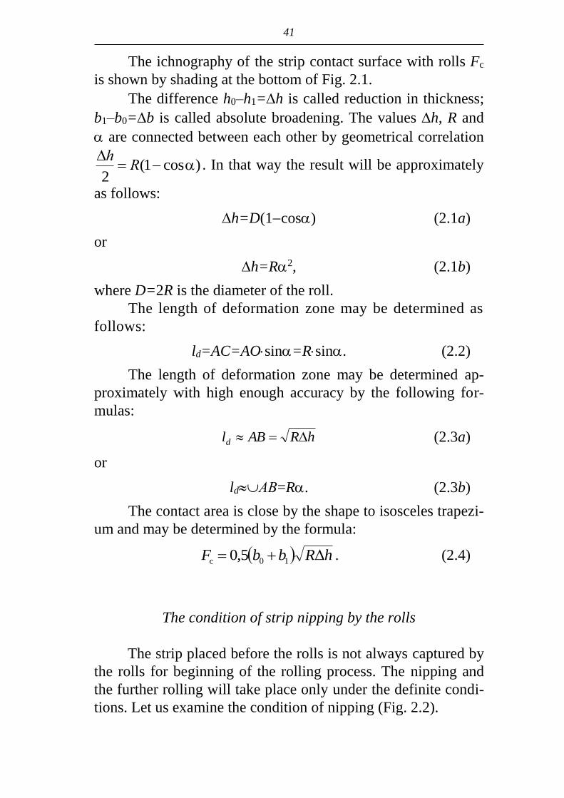
The ichnography of the strip contact surface with rolls Fc
is shown by shading at the bottom of Fig. 2.1.
The difference h0–h1=h is called reduction in thickness;
b1–b0=b is called absolute broadening. The values h, R and
are connected between each other by geometrical correlation
)cos1(2
Rh
. In that way the result will be approximately
as follows:
h=D(1cos) (2.1a)
or
h=R2, (2.1b)
where D=2R is the diameter of the roll.
The length of deformation zone may be determined as
follows:
ld=AC=AOsin=Rsin. (2.2)
The length of deformation zone may be determined ap-
proximately with high enough accuracy by the following for-
mulas:
hRABld (2.3a)
or
ldАВ=R. (2.3b)
The contact area is close by the shape to isosceles trapezi-
um and may be determined by the formula:
hRbbF Δ5,0 10c . (2.4)
The condition of strip nipping by the rolls
The strip placed before the rolls is not always captured by
the rolls for beginning of the rolling process. The nipping and
the further rolling will take place only under the definite condi-
tions. Let us examine the condition of nipping (Fig. 2.2).

42
Fig. 2.2. Nipping of strip by rollers
Let us place the strip before the rolls. The forces of the
normal pressure Р and friction force Т appear in points А and
А' – the place of contact of the strip with the rolls.
Рх is the ichnography of the force Р; that is expulsive
force, it strives to push the strip out of the rolls.
Тх is the ichnography of the force Т; it is the force draw-
ing the strip into the rolls.
The nipping of the strip by the rolls is possible under the
following conditions:
Рх≤Тх, but Рх=Р·sinα, Тх=Т·cosα, Рsinα≤Т·cosα.
After dividing into Р·cosα we obtain:
αcos
αcos
αcos
αsin
Р
T
Р
Р→
P
Ttg .
Substituting tg and fP
T we obtain:
fα . (2.5)
This is the condition of the strip nipping by rolls, which is
formulated in the following way: the angle of nipping has to be
less or equal to friction coefficient for nipping the strip by rolls.
The angle of nipping is measured in radians. The friction coef-
ficient at hot rolling of steels is equal to 0.3-0.5.
Taking the limiting condition of friction as fα , using
formula (2.1b) we will obtain the maximum reduction in the

43
moment of nipping during the rolling on roughing mill with
800 mm rolls diameter and friction coefficient f=0.5 (the rolls
with ragging).
1005,02
800
2
222max f
DfRh mm.
The expressions (2.1a; 2.1b) denote the direct dependence
of reduction during the process of rolling on the value of the
angle of nipping. The increase of the angle of nipping at the
given rolls diameter permits to increase the reduction, that is to
increase the efficiency of the mill due to decrease of the num-
bers of passes. Therefore one tries to carry out the rolling with
greater angles of nipping, but their values are limited by the
value of friction coefficient. In production practice the artificial
coarsening of the rolls (cuts, welding on etc.) is used to increase
the angle of nipping and consequently the reductions. Besides
the rolling speed is decreased at the moment of nipping. The
cone rolling ingots are feeding forward by the thin end to facili-
tate the nipping. It is possible to increase considerably the nip-
ping angle and consequently the reduction by means of forced
feeding of the metal into the rolls.
The value of the friction coefficient may be determined
according to the empirical formulas. The formula of B.P. Bakh-
tinov and M.M. Shtern is given below:
tkkkf 0005,005,1321 , (2.6)
where t is the temperature of metal, ºC; k1, k1 and k3 – the
coefficients taking into consideration the condition of surface
and the rolls material, the speed of rolling and chemical
composition of the metal.
The practice of manufacturing different rolled products
permitted to determine the coefficients of friction and maxi-
mum angles of nipping: the coefficient of friction amounts to
0.45÷0.52 during the rolling of blooms and ingots on the rolls
with cuts or welding on, and maximum angle of nipping
amounts to 26÷34º; the coefficient of friction amounts to
0.36÷0.47 during the rolling of sectional bars and maximum
angle of nipping amounts to 20÷25º; the coefficient of friction

44
amounts to 0.04÷0.06 during the cold rolling with lubricant and
maximum angle of nipping amounts to 4÷10º.
The scheme of forces action in zone of deformation will
be changed in case when the initial nipping has been accom-
plished and the deformation zone is filled by metal due to the
fact that the point of application of equivalent forces Р and Т is
displaced to the center of the contact surface. Its position is
characterized by the value of the angle (Fig. 2.3) and the an-
gle should be changed to in the equation (2.5) obtained
above. The condition of the metal nipping has the following
form in the stable process of rolling:
f. (2.7)
Fig. 2.3. The scheme of the force action
in the stable process of rolling
Taking =/2 we obtain the expression for determina-
tion of maximum possible angle of nipping for stable process
of rolling:
f2max . (2.8)

45
The angle of nipping can be increased two times as com-
pared with the condition of initial nipping. Consequently
the possibilities of initial nipping limit the reduction during
the rolling. The angle of nipping in the stable process of roll-
ing may be increased two times, what corresponds to in-
creasing of reduction (h=R2) to four times if the initial
nipping is ensured.
Longitudinal and lateral deformation
The height of the strip during the rolling is decreased for
the value of absolute reduction Δh. The length and width of the
strip has to be increased according to the law of metal volume
constancy.
The increasing of the strip length is called the longitudinal
deformation or stretching. The length of the strip after rolling is
equal to:
01 λ ll ,
where λ is reduction ratio, l0 is the initial strip length.
It is necessary to distinguish the reduction ratio in every
pass and the total rate of reduction.
The total reduction ratio for several passes is equal to:
n
n
F
F
l
l 0
0
tot , (2.9)
where ln and Fn are accordingly the length and cross-section
area of the strip after n-th pass.
It is not difficult to prove that the total reduction ratio is
equal to the product of separate reduction ratio:
n ...321tot . (2.10)
The increase of the strip width during the rolling is called
broadening or lateral deformation. In case when the value
of broadening is known the final width of strip will be equal:
b1 = b0 + Δb.

46
The number of formulas is proposed for broadening de-
termination. One of them is as follows:
1
0ln2
ΔΔ5,0Δ
h
h
f
hhRcb b
, (2.11)
where сb is the coefficient considering the influence of strip
width.
The rate of stretching and broadening change during the
rolling is determined by the law of the least resistance and de-
pends on dimensions of deformation zone: its length hRld Δ
and width b0.
The resistance of friction forces to the metal displacement
in linear direction will be greater than in transverse location and
the broadening will be increased and the stretching will be de-
creased in case when the length of the deformation zone ld is
greater than width b0 (ld>b0).
The resistance of friction forces to the metal displacement
will be increased in transverse location if the width of defor-
mation zone is greater than its length (b0>ld). It will lead to the
increase of stretching and the decrease of broadening.
The factors of the rolling increasing the length of the de-
formation zone (the increase of the absolute reduction Δh and
the rolls diameter D) will increase the broadening and reduce
the stretching.
The increase of the width of deformation zone (the in-
creasing of the initial strip width) will on the contrary lead to
increasing of stretching and decreasing of broadening.
Though dimensions of deformation zone change the cor-
relation between longitudinal and transverse deformation, the
greater part of metal reduced by its height, nearly 60-80%, is
used for increasing the strip elongation (increasing its length),
and only 20-40% is used for increasing its width.
Phenomena of the forward and backward slip at the rolling
Let us distinguish three sections in deformation zone – the
section of entry, any intermediate section at the arbitrary ,

47
the section of exit and write down for them the condition of
continuity of the metal flow passing via the deformation zone:
h0b0v0=hbv=h1b1v1. (2.12)
The equation (2.12) may be put to the following type:
F0v0=Fv=F1v1=const. (2.13)
The product of the cross-section area to the strip speed (v)
in the given area is called a second volume. The equation (2.13)
is called the condition of the constant second volume, which is
formulated in the following way: the equal metal quantity
should pass through every cross-section of deformation zone
per time unit.
The cross-section area of the strip is reduced as advances
from the entry plane to the exit plane. The speed of the strip
should increase continuously from the section of entry to the
section of exit of metal out of the rolls for observance of the
constant second volume, that is:
V0 < V < V1.
As it was shown by the experiments, the speed of the strip
end coming out of the rolls is greater than the circumferential
speed of the rolls. In the theory of rolling this effect is called
forward slip. The longitudinal speed of the strip is compared
with the horizontal projection of circumferential speed of the
rolls which is equal for any point of contact arc to:
vхroll = vrollcos, (2.14)
where is the current central angle.
The angle is changing from =α (entry section) up to
=0 (exit section) along the contact arc. For the exit plane if
=0 and соs=1 we obtain:
vхroll = vroll, (2.15)
that is the horizontal projection is equal to the circumferential
speed of the rolls.
Mathematically the relative forward slip can be written as
follows:

48
roll
roll1
v
v-vS . (2.16a)
The forward slip is often determined in percentage terms:
%100roll
roll1
v
vvS . (2.16b)
The speed of the strip at the exit at the known advance
(acceleration) is equal:
v1=vroll·(1 + S). (2.17)
Let as assume that vroll=2 m/seс, and S=5%, then:
v1 = 2(1 + 0,05) = 2,1 m/seс.
It is easy to determine the speed of metal entry into the
rolls using the strip speed in the plane of exit v1 and the law of
constant second volume (2.13):
F0v0 = F1v1,
wherefrom
.1
0
10 vF
Fv (2.18)
The ratio λ
1
0
1 F
F is the value opposite to the reduction ra-
tio, therefore the speed of the metal entry to the rolls is:
.λ
vv 1
0 (2.19)
The strip speed in the plane of entry to the rolls is less
than the speed of its exit so many times as many times the area
of cross-section per pass is decreasing (for the value of reduc-
tion ratio).
Let us continue the above given calculation and deter-
mine the speed of metal entry into the rolls, when reduction
ratio is equal for instance to =1.5. We obtain from (2.19)
the following:
4.15.1
1.2
λ
10 v
v m/sec. (2.20)

49
Thus the speed of metal entry into the rolls is less than circumferential speed of rolls. This phenomenon is called the backward slip.
Mathematically relative backward slip can be written down as follows:
αcos
αcos
roll
0rollback
v
vvS
. (2.21)
The value called the backward slip characterizes the ratio of speeds in the plane of metal entry into the rolls. This term empha-sizes that the speed of movement of the trailing end of the strip is less than the hori-zontal ichnography of circumferential speed of the rolls.
The forward slip is variable along the groove width during the rolling in grooves. It may be explained by the fact that the strip speed at the exit v1 is the same along the whole cross-section and radius and circumferential speed of the rolls are changing along the perimeter of the groove.
Let us examine for instance the case of the oval billet rolling in the round groove (Fig. 2.4). The speed of points 1 and 2 of the roll surface is different. As R2>R1, vroll2>vroll1. The forward slip in the point 1 and point 2 is equal:
;1roll
1roll11
v
vvS
.
2roll
2roll12
v
vvS
The coefficients of forward slip are as follows: 1+S1=v1/vroll1;1+S2=v1/vroll2.
This implies: 1roll
2roll
2
1
1
1
v
v
S
S
, that is S1>S2.
The maximum value of forward slip in the grooves takes place in the points of the groove having the minimum roll radius (at the peak of the groove). The forward slip has the minimum value in the points of the groove with maximum radius and the negative value (the backward slip) is possible.
Fig. 2.4. Scheme of
oval billet reduction
during the rolling in
the round groove

50
The change of strip speed along the deformation zone
The strip speeds were determined above only for the ex-
treme cross-sections of the deformation zone – entry and exit of
the strip out of the roll. The behavior of strip speed during the
deformation zone can be determined from the condition of con-
stant second volumes.
Let us assume that the speeds are uniformly distributed
per the height of the strip, and the broadening is absent, that is
b0=b=b1; then we obtain the following:
h0v0 = hv=h1v1, (2.22)
wherefrom
h
vhv 00
(2.23)
or
h
vhv 11 , (2.24)
that is the change of the strip speed within the deformation zone
may be determined using the condition at the entrance (h0, v0)
or the condition at the exit (h1, v1).
The current height of the strip h in any point of the arc of
contact may be determined according to the following formula:
h=h1+D(1–cos). (2.25)
Substituting the value h into the formulas (2.23) and
(2.24) for determination of v we obtain the following:
0
1
0
cos1v
Dh
hv
, (2.26)
1
1
1
cos1v
Dh
hv
. (2.27)
As the metal speed increases continuously from the sec-
tion of entry to the section of exit and at the same time the
speed of metal entry into the rolls is less than the speed of rolls
and the speed of exit is greater, it is evident that in deformation

51
zone there is such a section in which the speeds of metal and
rolls are equal. This section is called neutral. Its location in the
deformation zone is determined by the value of neutral angle γ.
The diagram reflecting the ratio of speeds of the rolls and
metal along the deformation zone is given on Fig. 2.5.
Fig. 2.5. The scheme of the acting forces
and change of speeds of the rolls
and strip in the deformation zone
The neutral section divides the deformation zone into two
zones of sliding: zone of backward slip (I) located from the
neutral section up to the section of entry and zone of forward
slip (II) located from the neutral section to the section of exit.
The speed of metal in any section of zone of backward slip is
less and in zone of forward slip on the contrary, is greater than
the ichnography of the circumferential speed of the rolls.
The difference of speeds of metal and rolls displacement
is the evidence that the strip during rolling is continuously slip-
ping relative to the rolls along the whole deformation zone, ex-
cept of one section – the neutral section. As the result the fric-
tion forces appearing on the surface of contact of the metal with

52
the rolls in the zones of backward and forward slip are directed
to opposite sides, and support metal making its deformation
more difficult. The neutral section is the division of metal flow within
the deformation zone. During the strip reduction as for height one part of metal is pressed from the neutral section forward along the run of the rolling. At that the speed of plastic shear of these particles is summarized with circumferential speed of the rolls forming zone of forward slip.
The other part of the metal on the contrary is pressed backwards from the neutral section against the run of rolling. In this case the speed of plastic shear of these particles is deducted from the circumferential speed of rolls forming the zone of backward slip.
The formula of Dresden is used for practical calculations of the forward slip value during the rolling:
2
1
γh
RS . (2.28)
The forward slip increases with the increase of the rolls
diameter and the angle and the decrease of the final height of the strip.
The angle of the neutral section , which is necessary for calculation of the forward slip is determined according to the formula of Pavlov I.M.:
f2
α1
2
αγ . (2.29)
The angle of nipping should be determined in radians. The following formula may be used:
R
hα . (2.30)
The knowledge of the forward slip is especially important for the correct calculation of the speed regime of rolling in the stands of continuous mills to avoid excessive tension or for-mation of the loop between the stands as it may cause the breakdown of the technological process as well as formation of the defects in the rolled metal.

53
The rate of deformation The average rate of deformation is determined by the exe-
cuted relative deformation realized during the time of metal
flow of the zone of deformation def:
def
avτ
u . (2.31)
Approximately the value def may be determined as
def=ld/v1. Then we obtain the A.I. Tselikov’s formula:
dl
vu
1
av . (2.32)
It is necessary to take into account the rate of deformation while determining metal resistance to deformation.
The distribution of pressures along the contact surface At present the pressure distribution along the contact sur-
face (contact pressure profile) has been well researched by means of the point load cells. It has been stated that the view of the pressure profile depends upon the conditions of rolling and first of all upon such factors as the ratio ld/hav, coefficient of
friction f and contact angle . Under the small values of parameter ld/hav (approximately
ld/hav<0.7) the pressure has the maximum value near the plane of entry (Fig. 2.6, a). It may be explained by the supporting ac-tion of rigid trailing end of the strip.
At higher values of parameter ld/hav, especially at
ld/hav>34 (thin strip) the clearly-defined peak appears on the profiles (epures) of pressure, which is located in the neutral sec-tion (Fig. 2.6, c). This character of pressures distribution is due to the action of friction forces. The sum of the linear supporting friction forces increases during the process of the displacement from the boundaries of deformation zone to the neutral section – consequently, the contact pressures are increasing. The peak height on the pressures profile depends upon the value of the friction coefficient.

54
a b c d
Fig. 2.6. The typical profiles of the pressure distribu-
tion along the contact arc: a – during the rolling
of thick strip; b – during the rolling of medium strip;
c – during the rolling of thin strip; d – at >
In case if the contact angle exceeds the friction angle, the
pressures profiles (epures) have the saddle-like form (Fig. 2.6, d).
In this case the linear tensile stresses, which are the cause of
the pressure falling on this area, appear in the rear part of the
deformation zone.
The average contact pressure and the force of rolling
One of the most important energy-power indexes of the
rolling process is the average contact pressure pav. The implica-
tion of this value is easy enough: it is the pressure which would
be under condition of the uniform distribution of pressures
along the contact surface.
The force of rolling Р may be presented as the product of
average contact pressure on the contact square area Fcont:
Р=pav Fcont. (2.33)
The calculation of the contact square area Fcont in majority
of cases doesn’t present particular difficulties. The main prob-
lem in the theory of calculation of the rolling force is in deter-
mination of the average contact pressure.
The value of the average contact pressure depends on the
yield strength of the metal to be worked and on the stress state
of the metal under deformation:

55
pav=yieldn, (2.34)
where n is the coefficient of stress state. The value of the coefficient of stress state may be present-
ed as the product of three coefficients:
n=n'n''n''', (2.35)
where n', n'', n''' are the coefficients taking into account the influence correspondingly of the external friction, external zones and tension of the strip ends. There are several theoretical and empirical formulas for determination of the value of these coefficients.
Turning moment, work and power of rolling
At the stable process of rolling the resultant of all forces Р
operating in the deformation zone has the vertical direction. In such a way the condition of balance of forces acting on the strip from the bottom and top rolls is fulfilled. The action of the reac-tive force Р from the side of metal to be worked on the roll is shown on Fig. 2.7. The turning moment produced by force Р relatively the center of the roll is equal to:
Мroll=Ра,
where а is the arm of the resultant Р relatively the center of the roll.
Fig. 2.7. On the calculation of rolling torque
The arm а is assumed to be determined as some part of
the length of the deformation zone: а=ld. The value is called the coefficient of arm moment or the coefficient of arm of the rolling power. Thus for two rolls we’ll obtain:
56
Мroll=2Рld. (2.36)
The problem of the calculation of the torque rolling is
reduced to the determination of the point of application of
force Р that is, to the determination of the coefficient of the
moment arm .
The line of action of the force Р is practically passing
through the center of gravity of the profile of the contact pres-
sures. Consequently the coefficient of the arm of the moment
depends on the character of the pressure distribution along the
contact arc. In case of uniform pressure distribution the point of
application of force P is situated in the middle of the contact arc
and =0.5. During the process of the thick strip rolling 0.5,
as the maximum of pressures is sheared to the plane of entrance
(Fig. 2.6, a). During the process of thin strip rolling 0.5, as
the maximum of pressures is sheared to the plane of exit. The
value of coefficient of the moment arm may be determined
strictly analytically if the law of the pressure distribution along
the contact arc is determined.
If the value of the rolling torque is known, the determina-
tion of the work and power of the rolling don’t present any dif-
ficulties.
The rolling work Аroll is equal:
Аroll=Мroll, (2.37)
where is the angle of the rolls rotation per period of rolling
the strip with the length l1:
SR
l
1
1 . (2.38)
The power spent on the roll barrel is equal:
Nroll = Мroll, (2.39)
where is the angle speed of the rolls rotation.
30
πω rolls
rollrollroll
nММΝ , (2.40)
where ω is the angular acceleration; nrolls is the rolls rotation
frequency, rev./min.

57
2.2. Continuous rolling
The main peculiarity of the process of continuous rolling
consists in the possibility of correlation of the separate stands in
continuous rolling mill through the strip to be rolled. Proceed-
ing from the metal solidity condition, the rates (speeds) of the
strip exit out of each mill stand as well as speeds of entry to the
next stand are to be coordinated. In the case of absence of the
interstand deformation these speeds as well as corresponding
strip sections are equal to each other. Then the solidity condi-
tion takes the form of condition of the metal constant second
volumes passing through each working mill stand:
t
lF
t
lF iiii 11 ,
Fivi = Fi+1vi+1,
F1,0v1,0 = F1v1 = … = Fi,0vi,0 = Fivi = … =
= Fn,0vn,0 = Fnvn = const. (2.41)
So, the main condition of the normal work for continuous
rolling mill is:
Fivi = ci = const.
The condition of metal solidity specifies also the main
physical peculiarity (feature) of continuous rolling process – the
force (power) interaction of continuous mill stands through the
strip to be rolled. Let us consider this peculiarity at the example
of interaction of the stands in two-high mill (Fig. 2.8).
While analyzing the possible separated rolling of the
strip in the stands with application of external forces to the
strip, one needs to take into account that the speed of strip
and dimensions of section of the latter at the exit out of the
given stand under other equal conditions depend only on the
value of external force (tension or support), and, thus, the
second volume of metal is a single-valued function of longi-
tudinal force (Fig. 2.9).

58
Fig. 2.8. Scheme of the rolling in two-high continuous mill
Fig. 2.9. Dependence of metal second volumes
in the first (C1) and second (C1 and C'2) stands
of continuous mill
Let us assume that the possible (during the separate free
rolling in the natural conditions) second volumes of metals
passing through stands are not equal to each other:
F1v1 = c1; F2v2 = c2; c2 > c1.
At the simultaneous (continuous) rolling of the strip in
both stands the condition (2.41) is to be observed. Equalizing of
metal second volumes passing through every stand under

59
invariable mill set up is possible only at the expense of action
of corresponding lengthwise forces.
The initial inequality of metal second volumes C1≠C2
leads in the process of continuous rolling to appearance of
lengthwise forces in the strip.
Interaction of the stands of continuous mill through the
strip to be rolled is accompanied with energy transference from
one stand to another.
Because of that the lengths of forward slip zones in the in-
teracting stands change as compared with the separate free roll-
ing. So, in the present case, the lengthwise tensile force arises
in the strip in the interstand space at C1<C2. The scheme of roll-
ing with front tension is acting in the first stand, and the scheme
of rolling with back tension takes place in the second stand.
According to it the following zones of forward slip are settled
in the process of continuous rolling:
1 е1 and 2 е2,
where γe1 and γe2 are neutral angles of forward slip zones in the
stands in conditions of free rolling.
The rolling with tension (as compared with free rolling)
evokes also the change of forces in the stands and correlation
of lengthwise and cross (transverse) metal flow in zones of
deformation. The elastic deformations of the stands are
changing (in accordance with the stiffness modulus of the
latter), as well as value of the strip thickness reduction,
spreading and also, in connection with loads change, the
speeds of the stand’s motors (according to stiffness of their
mechanical characteristics).
The stands of continuous rolling mill, the strip to be rolled
and electric drive form one complex with mutually depending and
mutually conditioned phenomena. The stand stiffness characteriz-
es quantitatively one of the most substantial dependences – de-
pendence between rolling force and thickness of the strip at the
exit of the stand. The degree of influence of the rolling moment
upon velocity of rotation of the stand rolls depends on the stiff-
ness of the drive mechanical characteristic.
60
Thus the equalizing of metal second volumes to the value
Cy takes place at the expense of corresponding change of all the
variables Fi, νroll,i, si):
Fivi = Fivroll,i(1+ si) = Су = const. (2.42)
The lengthwise force Qy (Fig. 2.8) appearing in this case
is an important technological factor determining rolling force,
change of metal form and quality of rolled products.
To create a greater interstand tension it is necessary to es-
tablish a greater possible inaccordance of initial metal second
volumes.
In the present case that can be realized by the way of es-
tablishing, for example, the greater frequency of rotation of
rolls in the second stand.
Then C'2>C2, and at continuous rolling the new equal
second volumes of metal C'2 are set and the quite specific ten-
sion with the force Q'2 (Fig. 2.9) is created here.
The value of tension (support) is evaluated by means of
coefficient of tension (coefficient of plastic tension) z:
yield2
xx
Kz .
At free rolling σx=0 and z=0.
Besides that, the degree of tension is evaluated by means
of coefficient of kinematic tension ω, easy to determine and
equal to relation of possible (at the separate rolling of strip in
the stands) second volumes of metal in adjacent stands of con-
tinuous mill:
ii
iii
vF
vF 111
.
At free rolling ω=1, at rolling with tension ω>1, and when
ω<1 we have rolling with support.
The normal continuous rolling process is possible under
condition that the lengthwise (longitudinal) stresses appearing
in the metal in the interstand spaces don’t exceed the definite
values conditioned with yield strength of metal, type of the
mill, technological peculiarities of rolling and so on.

61
That is why the degree of attainment of this or that tech-
nological effect from using the rolling with tension is limited
with ultimate conditions of the process.
Thus, the critical interstand tension is specified by condi-
tions of drawing the metal in preceding stand and slippage in
the following one as well as by conditions of the strip rupture.
The critical (limit) support is specified by conditions of the
slippage in preceding stand and drawing in the following one as
well as by conditions of the loss of longitudinal stability or
overfilling of the groove with metal and possibility of defects
appearance (rolled kinks, back fins and so on).
The above considered connection between longitudinal
forces and variables specifying metal second volumes, which
are passing through the stand takes also place in multistand
continuous mills. The interaction of stands in such a mill is like
to considered one, but presents a much more complex picture.
The change of adjustment of any stand in continuous mill
(change of the frequency of roll rotation, distance between rolls),
which can be realized in the process of rolling too, evokes the
corresponding change of drafts, forward slips as well as loadings
and speeds of motors (drives) of all the stands in the mill includ-
ing those arranged before the stand in question. As a result, the
rolling mill will work (while observing the restrictions) in a new
tension schedule with other technological effect.
Beside of controlling influences during the stable process
the rolling parameters can be changed in connection with influ-
ence of different perturbations.
The change of temperature and strip thickness along the
length, eccentricity of rolls, change of reel tension don’t lead, as
a rule, to breaking of the process current thanks to its ability of
self-adjusting, that is to renewal of speed coordination and set-
ting up of a new constant of continuous rolling (C).
Thus the essence of the process of self-adjusting is re-
duced to keeping the equality of metal second volumes passing
through all stands of the mill.
The process of self-adjusting is performed without con-
trolling influences at corresponding change of variables and
tension schedule.

62
Any perturbing influence in a given stand of continuous
mill leads to change of reduction and speed of metal in this
stand. In this case the change of speeds and on the whole of
metal second volume in the stand affects the work of other
stands through tension change in practice instantaneously.
2.3. Screw rolling
The feature of the screw rolling mills is the axial inclina-
tion of the working rolls to the axis of rolling and the same di-
rection of the rolls rotation. Scheme of the process of screw
rolling is given on Fig. 2.10 for two-high rolling mill with bar-
rel rolls.
The process of piercing the round solid billet into the shell
is the most widespread process in the tube manufacture. The
process is realized at the mill having two working rolls 1, guide
Fig. 2.10. The defor-
mation zone in two-high
piercing mill: a – the lon-
gitudinal sections in the
plane of bars; b – longitu-
dinal sections in the plane
of rolls; c – cross section;
1 – roll; 2 – plug; 3 –
guide; 4 – core; 5 – stop-
adjusting mechanism

63
unit in the form of two former bars 2. The piercing is realized
by means of floating plug 3 restrained in axial direction by the
core 4 and stop-adjusting mechanism 5.
The main technological angle is feed angle . The feed
angle is formed at the rotation of the roll axis around the axis
OZ, which is perpendicular to the rolling axis OX (Fig. 2.11).
The rolls are installed at the feed angle from 2º up to 40º in the
mills of different design and purpose.
Fig. 2.11. Scheme of installation of the roll of a screw
rolling mill and the decomposition of vector of circum-
ferential velocity of the roll: 1 – the housing of the roll
stand; 2 – the drum; 3 – the roll; 4 – the contact surface of
the metal with the roll; 5 – under deformation
Due to the indicated rotation the vector of circumferential
velocity of the roll u in every point of the roll contact with the
metal may be decomposed into the axial component ux, which
determines the movement of the metal along the rolling axis
(ux=usin); tangential component uy, which determines the ro-
tation of the metal (ux=ucos); radial component uz – the speed
of the billet reduction as per diameter.
The components of metal velocity vx, vy and vz differ from
ux, uy and uz. The sliding is arising on the contact surface and its
value is characterized by velocity coefficients:

64
x
xx
u
vη – axial velocity coefficient;
y
y
yu
vη – tangential velocity coefficient.
Each point of the wrought metal is moving at axial direc-
tion and is rotating around the axis of rolling, that is traveling
along the screw curve. The spiral path of displacing of the
points of metal within the deformation zone has the varied pitch
of the spiral due to the decrease of the radial size and stretching
along the axial direction; the pitches of the spiral are constant
before the entry to the deformation zone and after it. The
change of the velocities under consideration is taking place
along the length of the contact surface (Fig. 2.12).
Fig. 2.12. The change of the axial (а)
and tangential (b) metal (vx, vy) and
the rolls (ux, uy) velocities along the
length of the contact surface
a
b

65
The circumferential velocity of the rolls and its compo-
nents ux and uy are changing proportionally to the radiuses Rx,
which have the maximum values of the section called pinch and
are decreasing towards the entry and the exit out of the defor-
mation zone. The axial component of the metal velocity vx is
changing from v0 at the entry up to vshell at the exit of the defor-
mation zone with the condition of the constant second volumes:
v0F0 = vxFx = vshellFshell = const,
where F is the area of the metal cross-section.
As shell
0
0
shell
F
F
v
v ( is the reduction ratio of the pierc-
ing mill) and
x
x
x
F
F
v
v shell
shell
( x is the reduction from the
entry up to the arbitrary section x), then
x
x vv shell , that is
the changing of the axial velocity of the metal along the defor-
mation zone is proportional to the coefficient of reduction.
The coefficient of the axial velocity within the section of
exit by means of what the relative axial velocity of the process
is characterized, is equal to .shell
shell0
u
v
The coefficient 0 may take on the values less than 1
(Fig. 2.12, a, curve 1), 0=1 (curve 2) and 0>1 (curve 3) de-
pending on the material of the rolled billet, roll pass and tools
design, their surface conditions defining the friction coefficient,
the tolling of the mill. The interval of its changing amounts to
0.4-1.1, but as usual it is less than one. In the case when 0>1,
there is a neutral section xav n situated on the contact surface; in
this section the axial metal components of metal velocity and
the roll are equal (ux=vx); the zone of the axial backward slip is
located before the neutral section and the zone of forward slip is
located after it.
The coefficient of the axial velocity in the arbitrary sec-
tion x and the exit section 0 are related by correlation, which
is determined from the law of the constant second volumes:

66
x
x
xR
RГo . (2.43)
The distribution of tangential metal and rolls velocities
along the length of the contact surface is shown on the
Fig. 2.12, b. The radius of the roll is growing on within the en-
try cone of the deformation zone (l1) and accordingly the tan-
gential velocity uy is increasing proportionally to the radiuses in
each section of the roll and the angle speed of the roll. On the
billet the direction of the taper is opposite to the roll. The radius
of the billet in the entry cone is decreasing and accordingly the
tangential velocity of the metal is decreasing too. There is the
tangential neutral section xt.n on the contact surface; in this sec-
tion uy=vy. The character of alteration of the tangential metal
and rolls velocities is changing to the opposite one in the zone
of cone expansion. This may cause to appearing of the second
tangential neutral section at the end of deformation zone
(Fig. 2.12, curve 4). The angle velocity of the billet is affected
distinctly by the twisting of the latter under the influence of var-
iable tangential velocity of the roll surface.
The coefficient of tangential velocity in the section of exit
out of the deformation zone is designated as t; due to the twist-
ing in this section the equality vy=uy is attained and 1y
y
tu
v
(curve 5) or the ratio vy<uy and t1 (curve 6). During the pro-
cess of piercing the interval of changing t is equal to 0.8-1.1,
but usually t=0.95-1 if the diameters of the incoming billet
and the shell are approximately equal. t=0.6-0.9 in the sec-
tion of the nick.
The deformation zone may be divided to 4 zones along
the direction of piercing (Fig. 2.10, b): I – the zone of the solid
billet rolling (from the section of nipping up to the place of
meeting with the plug cone); II – the zone of introduction of the
plug cone into the metal; III – the zone of expansion on the
plug; IV – the zone of the shell rounding.
The reduction of the billet diameter, expansion and ovalling
of the cross-section of the metal take place within the first zone.

67
The deformation of the billet is going on at comparatively narrow
contact surfaces in the conditions of significant influence of exter-
nal zones. The non-uniform deformation leads to the appearance of
lateral tensile stresses in the central layers of the metal. The pe-
ripheral ring layer is formed at the turning of the billet, which (the
ring layer) is deformed more intensively than the internal one. This
layer causes the growing of lateral tensile stresses y in the central
volume. Simultaneously the external layer increases its length
along the axial direction to a greater extent than the central one.
The funnel-shaped recesses appear on the face surfaces. The level-
ing of stretching causes the appearance of additional longitudinal
tensile stresses x in central zone and compressing in peripheral
zone during moving away from the face surfaces.
Thus the scheme of stress state with two tensile stresses along the cross section and compressing along the direction of reduction is appearing in the central zone.
As far as the reduction of the billet is going on, the in-
crease of y may lead to destruction of the metal in the central zone and to the destruction of the cavity.
The value of the summary reduction of cross-sectional ar-ea of the diameter, at which the damage of the metal is begin-ning is called the critical reduction:
%100billet
crcr
d
d. (2.44)
The critical reduction is within the limits from 7 up to 16% depending on the natural plasticity and the heating tem-perature of different steels.
In case of reduction before the cone of the plug greater than critical one the central destruction of the metal is taking place, which causes skins creation on the inner surface of the shells and the defective tubes.
The solid billet is pierced by the cone of the plug in zone II. The thick wall ring formed by piercing is undergoing to re-duction by the rolls.
The gradual reduction of the shell wall is going on within the narrowing nip of the rolls and the plug in zone III and the wall thickness of the shell is finally formed.

68
The metal ovality is limited by the guides along the sec-
ond and the third zones. The shell has the coefficient of ovality
1.05-1.15 by the end of the third zone. The cross-section of the
shell becomes more round due to the rolling by the rolls in zone
four. The nipping of the metal by the rolls at the screw rolling
mill is divided to two stages: initial and secondary.
The initial nipping covers the period from the initial contact of
the billet and the rolls before beginning of its steady screw travel.
The supply of the billet to the rolls of the piercing mill is
made by the pusher. In case when the speed and the force of
pushing is too great, the width of the contact may exceed the
permissible value, and the rotation of the billet will be stopped.
Concurrently the condition of the axial drawing will be broken
and the initial nipping will not be accomplished. The force and
the speed of the pushing should be limited for accomplishing of
the steady nipping.
The secondary nipping covers the period from the contact
of the billet face and the plug up to the complete filling of the
deformation zone on the plug. The shutdown of the axial travel
of the billet with the preservation of its rotation is typical in
case of the nipping break.
The value of the cross-sectional area reduction per diame-
ter in front of the plug cone 0 has the significant influence on
the nipping. The increase of the feeding force and the decrease
of the plug resistance take place with the increase of reduction
0, the steadiness of the secondary nipping is increased.
The production of the shell with specified dimensions
dshellSshell from the billet with diameter dbillet may be accomplished
with different mill setup. The parameters, which determine the mill
setup are as follows: the distance between the rolls in nick; the ex-
tension of the plug outside the nick; mounting of the core.
The value of billet reduction in the nick per diameter is
used for evaluation of the setting parameters:
absolute value dnick=dbillet–dnick;
relative value %100billet
nicknick
d
d.
The value nick is usually equal to 8-20%.

69
For rational setting it is necessary to choose the optimal
reduction in front of the cone of the plug taking into account the
condition of the secondary nipping and prevention of the prem-
ature opening of the cavity in front of the cone of the plug:
0min<0<cr.
The growth 0 causes the increase of the steadiness of the
nipping on one side as well as the probability of defects appear-
ing. In practice the reduction in front of the plug cone is chosen
within the limits 3-8%.
At the feeding angles 8-10º the length of the contact sur-
face in the cone of piercing (l1) and the cone of expansion (l2) is
determined by expression:
1
nickbillet1
tg2
ddl (2.45)
and
2
nickshell2
tg2
ddl , (2.46)
where 1 and 2 are the angles of the roll coning in zones l1 and l2.
The maximum width of the contact surface in the nick is
determined according to the following formula:
nick
nicknick
nicknicknick Δr
rR
rRb
, (2.47)
where Rnick, rnick the radius of the roll and the radius of the billet
in the nick; rnick is the absolute partial reduction along radius
of the billet in the nick.
For approximate determination of the average width of the
contact surface in the cone of piercing the following formula
may be used:
b1av=0,67bnick, (2.48)
in the cone of expansion:
b2av=0,8bnick. (2.49)

70
The average contact pressure in the cone of piercing is de-
termined according to the empirical formula:
avyield
2
nick
nick
nickav1 )7,21)(
28,1(
r
bp (2.50)
in the cone of expansion р2av=0,75 р1av.
For deformation of the average value of the yield strength
of the metal yield av the rate of deformation may be estimated
according to the following expression:
nick
nickav
2r
vu , (2.51)
where vnick is the circumferential speed of the roll in the nick.
The overall stress on the roll will be equal to:
av2av2av2av1av1av1 lbрlbpN . (2.52)
Basing on the experimental data the stress Q, having the
effect on the plug amounts to:
Q=(0,2…0,5)N, (2.53)
on the guide:
Nguide=(0,1…0,4)N. (2.54)
The rolling torque may be estimated approximately ac-
cording to the formula:
М=Na, (2.55)
where the arm of the moment:
av
avav 12 R
rba , (2.56)
where 21
2av21av1av
ll
lblbb
is the average value of the width of the
contact surface; rav and Rav – the average values of the billet
radius and the roll radius.

71
2.4. Drawing
The drawing of the ferrous and non-ferrous metals is ac-
complished in overwhelming majority of cases in cold condi-
tion. The lubricant is used for reduction of friction forces.
The cold deformation is accompanied by the metal hard-
ening – the strength properties are increasing significantly and
the plasticity is decreasing. The possibility of deformation per
one drawing are limited by the plastic properties of the metal
and the strength of the leading end of the obtained profile pass-
ing the drawing force to the deformation zone. The drawing
stress should be lower than the breaking point of the metal at
the exit out of the deformation zone.
The following indexes are the most used as characteristics
of the metal deformation during the process of drawing:
reduction of cross-sectional area %1000
10
F
FF
(F0 – the net area of the billet; F1 – the net area of the
profile at the exit out of the drawing die);
elongation (reduction) ratio 1
0
F
F .
The elongation (reduction) ratio may be estimated accord-
ing with the formula 21
20
d
d during the drawing of the round
profiles with diameter d1 from the round billet with diameter d0.
The indexes and are connected between each other by
the constant volume condition with the following correlation:
1 (2.57)
and
1
1. (2.58)
The value of the elongation (reduction) ratio per one drawing
as usual doesn’t exceed the value 1.3-1.4. The maximum drawings
(1.8-2.0) may be achieved in the processes of tube drawing

72
on the long mandrel when there is possibility of the passing the
drawing force to the deformation zone via the mandrel.
The deformation becomes non-uniform at small values of
the elongation ratio per one drawing and is concentrating in the
outlaying layers. Therefore the minimum value of the unit
strain is also limited. For the round solid profile min=1.1-1.2.
The total reduction of cross-sectional area per n drawings
is determined according to the following formula:
0
0
F
FF n , (2.59)
where Fn is the net profile area obtained after n-drawing.
The maximum total reduction max is limited by the sharp
decrease of the metal plasticity. The value of the total reduc-
tions is usually equal to 40-60% and may amount the maximum
value of 90-95%. It is necessary to carry out the intermediate
heat treatment for recovery of the metal plastic properties and
the possibility of its further deformation.
The succession of the draws accomplished up to the
manufacture of the finished product or up to intermediate
heat treatment is called the drawing routing. The drawing
routing may be different as per the number of draws so as
the used unit reduction at the same total reduction . As
usual the gradual decrease of unit reductions is foreseen tak-
ing into account the metal hardening during the formation of
the drawing routing. The higher reductions during the first
passes cause the increase of the uniformity of deformation
along the section of obtained profile.
The work of deformation and contact friction during the
process of drawing is turned into the heat, that results in signifi-
cant increase of the metal temperature especially at high speeds
of drawing. The product temperature should not exceed 250ºC
as the ageing of the metal is going on at the higher temperature.
The conditions for the better heat sink and better lubricant are
provided for increase of the drawing speed. At present the
speed of the low carbon steel wire drawing amounts to
2400 m/min. In respect to the minimum drawing forces the op-
timal values are considered to be the speeds 900-1500 m/min.

73
Let us examine the character of the metal flow in the de-
formation zone according to the changes of the grid during the
drawing of the round profile through the tapered die (Fig. 2.13).
Fig. 2.13. Scheme of changing the grid
in the deformation zone during the drawing
The bend of the horizontal line of the grid had place near
the plane of entry and the reciprocal bend of the inclined lines
to the horizontal position had place near the plane of exit place.
It is the evidence of the shearing deformation at the boundaries
at the deformation zone with the external zones.
The vertical lines of the grid get the camber along the
drawing direction, that is the central layers of the metal are
moving with the greater axial speed than outlying ones. It leads
to the additional shears in all layers especially in close to con-
tact ones. The shears in central layers are
minimum ones. The action of the contact
friction is the cause of the shear defor-
mations. The value of the shears is in-
creasing with the increase of the coning
angle of the die , reduction and the co-
efficient of friction in the die channel f.
The die channel profile has several
areas of different purposes (Fig. 2.14).
The entry zone 1 is used for protec-
tion of the billet against the scorings on
the die edges. The lubricating cone 2 pro-
vides for the lubricant entry to the die
Fig. 2.14. The profile
of the die channel:
1 – entry zone;
2 – lubricating cone;
3 – working cone;
4 – calibrating collar;
5 – exit zone

74
channel and improves the lubricant pickup by the billet surface
at the entry to the working cone. The main deformation of de-
creasing the cross section area of the billet is accomplished in
the working cone 3. The calibrating cylindrical collar 4 does not
change the profile section dimension, but increases the die du-
rability significantly. The exit zone 5 prevents the calibrating
collar from crumbling and the out coming from the die profile
from the scorings on the surface.
As usual the dies with the angle of the working cone
=5-15 are used.
There is a number of empirical and theoretical formulas
for determination of the drawing force (Рdraw) and the drawing
stress (1=Рdraw/F1). One of them the most simple (Gavrilenko
formula) has the following form:
tgα11λσσ avdrav1
f, (2.60)
where 2
σσσ 1drav0drav
avdrav
is the average value of the tensile
stress of the metal to be worked before and after drawing.
It is possible to estimate the power used for drawing, if
the drawing force is determined as Рdraw=1F1:
Ndraw=Рdrawvdraw, (2.61)
where vdraw is the drawing speed.
2.5. Pressing (extrusion)
There are different methods of pressing due to the scheme
of the relative displacement of the pressing tool (the ram) and
profile to be extrusion: with direct, side and reverse metal flow.
The process of the forward (direct) extrusion is the most
widespread in the world practice. By means of this method it is
possible to produce the solid and hollow profiles of the wide
size range up to the sizes close to the size of container.
Scheme of the direct extrusion is shown on Fig. 2.15.

75
а
b
Fig. 2.15. Schemes of the direct extrusion:
a – solid profile; b – hollow profile
The billet 1 heated up to the temperature of extrusion is
placed into the container 2 (Fig. 2.15, a). The mold 4 forming
the profile of the product 5 is placed at the exit side of the con-
tainer in the mold holder 3. The pressure from the main press
cylinder is passed on the billet via the ram 6 and pressure pad 7.
Due to the high pressure the metal is flowing into the working
mold channel forming the profile corresponding to the profile
of mold channel. The tool in the form of core 8 fixed on the ram
and passing through the hole in the billet is introduced into the
mold channel for producing the hollow profiles. The tool in the
mold channel can be retained by another method without resort-
ing to the billet piercing.
The mold is placed on the front end of the hollow ram for
backward extrusion (Fig. 2.16). The pressure of the ram brings
to the metal flow out of the mold hole at the direction reverse to
the direction of the ram travel.

76
Fig. 2.16. Scheme of extrusion
with reverse metal flow:
1 – billet; 2 – container; 3 – plug; 4 – ex-
trusion die; 5 – ram; 6 – pressed product
The process of the backward extrusion is notable for
the absence of friction forces on the walls of container due to
the absence of the billet sliding along the container walls.
The extrusion differs from other processes of metal
forming with what at different stages of the process the
stress state, the metal flow and pressing force are different.
The pressing process may be divided to three successive pe-
riods depending on the force and deformation conditions
(Fig. 2.17):
I – pressing out (upsetting) of the billet in the container
and filling of the whole container volume by the metal. The
pressing force is increasing from zero up to the maximum
value (in case of direct extrusion it is greater than in case of
reverse one);
II – steady-state process. The force is not changed dur-
ing the backward (indirect) extrusion, during the direct ex-
trusion it is decreasing due to the reduction of the billet
height and the surface of contact of the billet and the con-
tainer walls;
III – the final stage of the process. The side supporting
stresses are increasing with decreasing of the butt-end and
the force of pressing increases sharply.

77
Fig. 2.17. The change of the force
during the process of extrusion:
1 – with direct flow of the metal;
2 – with reverse flow of the metal
The temperature-speed regime of pressing (extrusion) in-
fluences significantly on the character of metal flow out of con-
tainer through the extrusion die channel as well as the tempera-
ture difference of the billet and the container walls and along
the billet section; the conditions of friction under the ram, on
the container walls and in the extrusion die channel.
Let us examine three the most typical kinds of defor-
mation zone during the process of pressing.
The first kind (Fig. 2.18, a) is characterized by the fact
that the deformation zone is concentrated near the extrusion die,
the rest of the billet part is not plastically deformed, it is im-
movable during the backward extrusion or is traveling to the
deformation zone during the process of direct pressing. This
kind of deformation zone is observed during the backward ex-
trusion as well as during the direct one if the coefficient of fric-
tion is low. Mechanical properties will be homogeneous along
the section and the length of the pressed product.
The second kind of deformation zone is observed at av-
erage values of the friction coefficient and the presence of
some heterogeneity of metal mechanical properties along the
section of the billet (for instance, in case of non-uniform heat-
ing of the billet). The deformation zone is extending on the
whole length of the billet (Fig. 2.18, b). The flow of the inner
layers (volume V1) is going on faster than of the external ones

78
(volume V2). The flow of the external layers is restrained by
the friction forces on the container walls as well as the greater
resistance to the metal deformation, sub-cooled due to the con-
tact with the container walls. The mechanical properties are
changing along the length of the pressed product.
а b c
Fig. 2.18. Three types of metal flow
at the pressing (extrusion)
The third kind of deformation zone (Fig. 2.18, c) is ob-
served in the conditions of pressing with the bad lubricant at the
high value of the contact friction, at non-uniform heating of the
billet, in the absence of the heating of the container. The defor-
mation zone then is characterized by the high irregularity of the
metal flow. The greatest intensity of the deformation takes
place in the volume V1 located immediately against the extru-
sion die. The volume V2 is flowing from the periphery to the
billet axis as the deformation is developing. The volume V3
borders to the surface of pressure pad. The metal flow to the
center causes the transfer of the metal from the side surface of
the billet to the face of the pressure pad.
The pressure pad is approaching the extrusion die during
the final stage of the pressing process. The metal volume feed-
ing the central zone is reducing and under pressure pad the fun-
nel-shaped hollow is formed – press-funnel where the surface
79
defects of the billet are concentrated. The pressing (extrusion)
is stopped before the approach of the front end of the funnel to
the extrusion die channel to avoid the ingress of the funnel to
the product. Butt-end is left and then it is cut.
The value of the deformation during the process of press-
ing is characterized by the following indexes:
degree of deformation:
%1000
10
F
FF, (2.62)
where F1 is the total area of all the holes of extrusion die;
reduction ratio:
.1
0
F
F
(2.63)
The value of the reduction ratio during pressing (extru-
sion) usually amounts to 20…30, and while pressing for exam-
ple aluminum alloys – up to 100.
The empirical L.V. Prozorov’s formula became widely
used for calculation of the pressing force:
1
ts lnF
FFncР , (2.64)
where ts is the tensile strength within the pressing temperature
range; F is the cross-section area of the container; F1 is the
cross-section area of the pressed product; n is the coefficient
characterizing the metal friction between the billet and
container and determined according to the following formula:
n = 1+0.08H/D, (2.65)
where H is the height of the billet, D is the diameter of
container; с is the coefficient characterizing the friction forces
and non-uniformity of stress distribution in the billet; during the
pressing of the solid sections с=4, of smooth-walled tubes –
с=5-6, ribbed tubes – с=7.
The pressing (extrusion) process with the other kinds
of metal forming has its advantages and disadvantages.

80
Advantages:
the scheme of the all-round non-uniform pressing in-
creases the plasticity of the metal what permits to pro-
cess the low plasticity alloys;
the products with complicated configuration of the
cross-section may be produced by the way of pressing
(extrusion) method;
readjusting for transition from one kind of products
manufacture to another is very simple and this makes the
process of pressing competitive at manufacturing of
small production lots;
the high precision of products produced by pressing.
Disadvantages:
considerable metal loses for tailings (butt-end and press-
funnel);
non-uniform structure and mechanical properties along
the section and the length of the product;
comparatively low efficiency because of the long time
auxiliary operations.
2.6. Smith (free) forging
While obtaining products by the way of smith (free) forg-
ing the primary billet (ingot) is processed by repeated action
from the hammer head or press until the moment when the solid
acquires the set shape and size. Smith forging is used in small-
lot and individual production of forged pieces with various
mass including the most heavy (up to 250-300 tons). Small and
medium size forged pieces (up to 0.5 tons) are produced from
the rolled billets. More heavy forged pieces are manufactured
from the ingots with round, square and polyhedral section.
The value of deformation during the smith forging is de-
termined by relative change of cross-section areas:
%1000
10
F
FF (2.66)
81
or by forging ratio:
1
0
F
Fy , (2.67)
where F0, F1 – areas of cross section of forging piece before
and after deformation.
The forging ratio shows how many times the cross sec-
tion of the billet changed during the forging, that it charac-
terizes the level of the hammering of the metal. The greater
is the forging ratio, the higher are the mechanical properties
of the metal. The practice has stated that to obtain forged
pieces of high quality from construction steels the forging
ratio for ingots should be no less than 2.5-3, for rolled metal
1.1-1.3. One should take into account the forging ratio no
less than 10-12 during the forging of steels containing diffi-
cult-to-break carbides and eutectics.
The hot metal forming influences essentially on the
structure of metal. The primary crystals (dendrites) are
crushing and stretching in the direction of the greater defor-
mation during the forging of the cast metal. The metal ob-
tains the grain microstructure as the result of the recrystalli-
zation processes and fibrous macrostructure due to the impu-
rities location at the boundaries of the deformed grains. The
metal becomes more strong and plastic as the result of forg-
ing. The metal obtains anisotropy in consequence of fibrous
macrostructure formation. The increase forging ratio leads to
the increase of metal plasticity characteristics along the fi-
bers and their falling in transverse direction.
It is necessary to take into account the direction of the fi-
bers during the development of the process of components pro-
duction due to the anisotropy of the metal mechanical proper-
ties: the fibers have to turn round the component profile or to
coincide with the direction of tensions action during the com-
ponents’ loading and where possible haven’t cross each other.
The technological process of forged pieces production
may be divided into the main and auxiliary operations. The
main forging operations are as follows: setting, drawing, pierc-
ing, bending, cutting, twisting etc.

82
The drawing of the forging piece is being sketched first of
all on the base of the drawing of the finished component during
the process of development of the technological process of
forging components production. For this purpose allowances,
tolerances and if required overlaps are being chosen according
to the standard.
Allowance is the provided exceeding of the forging piece
dimensions in comparison with the nominal component dimen-
sions for obtaining required dimensions and pure surface after
the finishing by cutting.
Tolerance is the difference between the greater and the
smallest dimensions limit of the forging (permissible deviations
of dimensions).
Overlap is the increasing of the allowance making the
forging piece configuration more simple due to the impossibil-
ity or inexpediency of the forging piece production according
with the component contour.
The mass of the forging piece or the billet is determined
proceeding from the volume calculated from dimensions indi-
cated on the drawing. For volume calculation the forging piece is
divided to parts having the simplest geometry. It is possible to
calculate the mass of the billet knowing the density of the metal.
The total mass of the billet (ingot) is obtained as the sum
of forging piece mass and mass of wastes in the form of re-
moved metal and bottom part of the ingot, punching of the
forged piece, loss of metal during heating and during the heat-
ing of the billet.
The cross section area of the billet is calculated according
with the specified degree of upsetting.
The overall index of precision called the coefficient of the
usage of forging piece metal during machining is used for com-
parison of different technological processes and the equipment
efficiency:
p.f
comp
tr.mecG
GK , (2.68)
where Gcomp and Gf.p is the mass of the finished component and
the mass of the forging piece.

83
This index characterizes the degree of perfection of the
forging piece.
As usual Кmec.tr=0.05-0.3 for forged pieces obtained by
smith forging.
Another important index characterizing the degree of
perfection of the forging technology is the yield billet
f.p
G
G
where Gbillet – the billet mass. During the forging from the
ingot =0.3-0.7, during the forging from rolled billet
=0.7-0.9.
The product Кm.u= Кmec.tr is the cumulative rate of the
metal usage during the whole technological cycle of the ready
component production. At smith forging Кm.u=0.02-0.3.
The size range of the main forging equipment (hammer,
press) is determined according dimensions of the billet (ingot)
and the transition diagram of forging.
The most difficult operation of the given technological
process is oriented on. The press force and the mass of the
hammer falling parts are determined by calculations accord-
ing to the empirical and theoretical formulas given in special
reference literature. The approximate data about the equip-
ment used for hammer forging and press forging are given in
Table 2.1.
Table 2.1. The approximate data about the equipment used for hammer
forging and press forging
Mass of
the falling
parts of hammer,
kg
Mass
of forging
piece, kg
Billet section
(square side,
mm)
Press
force,
MN
Ingot
mass, t
100 0.5-2.0 50 6 0.5-2.0
300 3-10 85 10 4-8
500 8-25 115 20 15-30
1000 20-70 160 30 30-60
3000 100-320 275 60 60-120
5000 200-700 350 100 150-250

84
2.7. Hot die forging
The metal flow is limited by the surfaces of die cavities in
case of using this method of metal forming. The die cavity (die
impression) is being filled up by the metal, the cavity has the
form of the product – forging piece.
The die forging if to compare with the smith (free) forging
provides for higher efficiency, dimensional precision and better
quality of the products’ surface. The components with the most
complex shape may be received by forging with considerable
reduction of technological operations.
The forging tool – the die has the considerable cost and
may be used for production of only one configuration forging
pieces, that’s why die forging becomes profitable only in case
of mass serial production.
The most widespread method of hot die forging is the
forging in open die with the burr (Fig. 2.19).
Fig. 2.19. Forging
in open die with the
burr: 1 – moving
die; 2 – bottom die;
3 – product; 4 – burr
The essence of the burr method consists in the fact that
due to the excess of metal the forging piece is produced with
the burr at the place of the die parting. After finishing the plas-
tic working the burr is removed on the shaving die. This meth-
od of forging is widely used in manufacturing, because it en-
sures the effective filling of the die cavity in spite of the metal
losses in the form of burr.
Forging in the opened dies is characterized by the direction
of the metal displacement into the burr slit perpendicular to the
direction of the die movement. The burr thickness is reducing

85
during the process of forging. The filling of the die impression
by the metal may be divided into several stages (Fig. 2.20). The free upsetting of the billet is going on during the first
stage. In case of complex shape of the die the partial piercing or extrusion of the metal into the recesses of the cavity is possible.
The second stage of forging begins from the moment of the billet contact with the side walls of the die. The deformation force at this stage is increasing due to the supporting action of the side walls of the die and the ap-pearance of friction forces on the side surface of the impression. This stage of forging is finished by the moment of beginning of the burr formation.
Only the angles of the die cavity remain unfilled by the metal by the beginning of the third stage. The sur-plus metal of the billet is displaced in-to the groove. That time the burr is ac-complishing its main function, which consists in closing the die cavity. Now the resistance to the metal flow into the unfilled angles of the die cavity is becoming less than into the groove. The die impression becomes filled by the end of the third stage.
In case the forging piece by the moment of the impression filling has the height greater than it is necessary, fourth stage of the process – additional forging is required during the process of which the excess of metal will be displaced into the burr.
It is necessary to take into ac-count that the stages of forging of complex shape forging pieces are non-simultaneous along the perimeter of the forging piece. At the beginning the angles of the die are being filled only in separate places.
a
b
c
d
e
Fig. 2.20. The stages of
metal flow during the fill-
ing of the opened die: a –
initial position of the bil-
let in the die; b – position
of the billet at the mo-
ment of the first stage fin-
ishing; c – finishing of the
second stage; d – finish-
ing of the third stage; e –
the forth stage – addition-
al forging

86
Demolding of the forging piece presents some difficulties due to retaining of the latter by the friction forces in the die cavi-ty. The side walls of the cavity are made with the inclination to facilitate the demolding of the forging piece and the forging piece is produced with the lap, though it is connected with the forging piece shape distortion and additional metal consumption.
The dies have to be lubricated thoroughly, what gives the possibility to decrease their inclinations and laps on the forging pieces. The lubricant is necessary for increasing the die strength.
Deforming force Р, which is necessary for deformation accomplishing at the final moment of forging, presents the sum of force necessary for metal deformation in the die and the force necessary for the burr deformation.
For the elongated forging pieces having the form similar to rectangular with the long side a:
Р=yield(1+fs/h)Fburr+(2fs/hburr–0,25+1,25lna/hburr)Fp, (2.69)
where s is the width of the bridge; hburr is the thickness of the
burr; f is the index of friction; Fburr is the area of projection of the burr bridge; Fp is the square of the forging piece projection.
For the forging pieces having the form similar to the round with the diameter d:
Р=yield(1,5+fs/hburr)Fburr+(2fs/hburr–0,375+1,25lnd/hburr)Fp.(2.70)
a b c
Fig. 2.21. Schemes of forging in closed dies
Burr-free forging in closed die method consists in billet placing into the die cavity 1, to which its another part 2 enters as into the guide (Fig. 2.21, a, b). In this die the whole volume of the billet metal remains in the forging piece. The exit for the

87
burr is not provided for. This die doesn’t provides for the free forging piece removing from the impression. The forging piece is removed from the die cavity by the pusher 3 (Fig. 2.21, c) or the female composite dies are used.
The forging angles of relatively small sizes are used for
decreasing the pushing force. In case of composite dies usage
the inclinations are not necessary.
The variations of the billet volume should be insignifi-
cant during the forging in the closed die. The smaller than
required billet volume leads to the underflow of the die an-
gles and forging pieces defects. The greater billet volume
leads to the thrust of the die, decrease of its longevity and
may bring the die damage.
The burr formed in the split at the place of the die joint is
insignificant; its thickness is not changed during the process of
forging and the direction of the run-out coincides with the di-
rection of the die movement.
The billet processing may be accomplished in one or sev-
eral impressions during the opened forging as well as during the
closed one. In case of multi- impression forging the billet is
changing gradually during the transi-
tion from one impression to the other
and in the finishing pass it is finalized
as to the shape and dimensions.
The essence of the process of ex-
trusion consists in the following: the
billet is positioned in the cavity of the
closed die having the outlet, which the
part of the metal is extruded through
beyond the bounds of the main cavity
(Fig. 2.22).
The wastes are not envisaged
here, excluding the excess part of the
billet volume formed during out-of-
tolerance cut of the metal for billets.
Unlike the cavities in the closed die, for the forming of shape
separate elements the die for extrusion has the open cavities
with the outlet.
Fig. 2.22. The scheme
of the forging by extru-
sion: 1', 1'' – the com-
posite parts of the die;
2 – the body of the forg-
ing piece; 3 – the core
part of the forging piece

88
The obtained forging piece consists of the body located in
the main part of the cavity and the core part extruded through
the hole in the die cavity.
The extruded forging pieces have the higher quality, the
absence of the cracks and other defects due to the plasticity in-
creasing in the conditions of uniform compression at the high
hydrostatic pressure.
Every method of forging described above has its ad-
vantages and disadvantages, but the forging in the closed dies is
more rational as only the small size burr is possible during this
process (0.5-1%), the quality of the forging pieces is higher
than from the opened dies. The main disadvantage of the meth-
od of forging in the closed dies is in its non-universality and
limited nature of rational shapes of the forged pieces.
2.8. Sheet metal stamping
Sheet metal stamping is used for manufacturing the
products from sheet, plate and strip material without any
significant change of the billet thickness. All technical met-
als and alloys having good plasticity are used for sheet metal
stamping. Metal deformation is usually carried out in the
cold state and only for processing of the plates with the
thickness more than 100 mm and low-plastic alloys it is ac-
complished in hot or warmed-up state.
The variety of the products’ shapes and sizes manufac-
tured by sheet metal stamping is determined by significant
number of stamping operations differing by the character of the
billet shape changing and by the conditions of the stress. They
may be divided to two categories: separating (cutting, blanking,
punching) and shape changing (bending, stretching, reduction,
burring, shaping and others).
The cutting operation consists in separation of the billet
part along the open contour. Mostly cutting is the blanking op-
eration. Cutting of the metal is accomplished by the shears with
parallel blades or incline blades as well as by circle shears.

89
The separation of the billet part along the closed contour is called blanking. The separated part is intended for further processing. The operation is called punching in case when the remained part of the sheet undergoes the further processing. The operations of punching and notching are accomplished in the dies. The effort Р, which is necessary for punching and notching is determined according the following formula:
Р=1.3ПHav, (2.71)
where П is the perimeter of the contour, which the punching or notching is accomplished along; H is the thickness of the sheet;
aver=(0.8-0.9)ult is the value of the shearing strength. The operation changing the shape provide for the manu-
facture of spatial component with the required shape and di-mensions. Let us examine some the most often met operations of shape changing.
The bending in dies is widely used for manufacturing the different products. The bending process is accompanied with the stretching of the external fibers of the bending material and compression of the internal ones, at that the value of the relative deformation is increasing along with the decreasing of the bending radius. The minimum internal value of the bending ra-dius depends on the metal plasticity and is taken within the lim-its rmin=(0.25-0.3)h, where h is the plate thickness.
The elastic properties of the metal lead to the changing of the bending value for the angle of springing, which may be 6-12º for steel during the bending for 90º.
The effort Р during the bending may be determined ac-cording the following formula:
ult
2
σ7,0hr
BhP
, (2.72)
where В, h is the width and thickness of the bending billet; r is the radius of bend along the internal contour.
The stretching presents the operation of transformation of the flat or hollow billet into the hollow body (cap, cup) accom-plished without thinning as well as with thinning of the wall. The process of stretching may be accomplished for several suc-cessive operations in a number of dies with gradual decreasing

90
of the cup diameter. The stretching (Fig. 2.23, a) is accom-plished in a die under the pressure of the punch 2 on the center part of the billet 1 placed above the hole of the die 3. Passing through the die hole, the center part of the billet is pulling the remaining part of the billet, what leads to its folding and reduc-tion of the diameter. The compression stresses appear in a circu-lar direction during this process and they may lead to the loss of the flange stability and riffles formation. To exclude this effect the ring holders of different constructions are used (Fig. 2.23, b).
a
b
Fig. 2.23. The scheme of stretching operation:
a – without holder; b – with holder;
1 – billet; 2 – punch; 3 – die; 4 – holder
The value of the force P acting from the side of the
punch is limited by the strength of the walls and bottom of the
manufactured product. The work-hardened low-alloyed steel
permits the production of the cup with diameter 1.8-2.0 times
less than the billet diameter per one pass. The possible de-
creasing of the diameter is smaller to 1.2-1.4 times during the
next operations of stretching due to the decrease of plasticity.

91
The edges of the punch and the die are rounded by the radius
equal to: rpunch=(4-6) h; rmatrix=(5-10)h to reduce the stresses
and possibilities of the billet damage.
As a rule the stretching is accomplished with the use of
lubrication of the contact surfaces of the die and the draw ring.
Different oils are used as lubricants, in many cases with fillers
(graphite, chalk, talc) as well as soap greases.
Inward flanging is used in those cases when it is neces-
sary to produce the neck at some place of the flat billet with the
hole (Fig. 2.24).
Fig. 2.24. The scheme of inward flanging:
1 – billet; 2 – punch; 3 – die
It can’t be permitted the increase of the hole diameter
more than 1.4-1.5 times to avoid the appearance of the cracks
along the edge of the hole.
Several operations are combined in one die to increase the
efficiency during the manufacturing of the components by the
methods of sheet metal stamping (separating, shape changing in
this or that combination: cutting and notching, cutting and
bending, punching and stretching etc.) – so-called combined
stamping.

92
3. PROCESSES AND EQUIPMENT OF ROLLING
3.1. Classification of the rolling mills
The rolling mills are classified according the following
basis: the number and arrangement of the rolls in the roll
stands; the arrangement of the roll stands; purpose.
The number and arrangement of the rolls in the roll stands
The stands differ according to above mentioned basis as
follows (Fig. 3.1):
two-high mill stand (duo);
three-high rolling stand (trio);
four-high stand (quarto);
multi-high stands (six-high, 12-high, 20-high etc.);
universal mill stands;
special construction mill stands.
Two-high-, four-high- and multi-high mill stands may
be of reversing type (with variable direction of the rolls rota-
tion) as well as irreversible (with the constant direction of
the rolls rotation). The rolling is accomplishing only between
two working rolls in the quarto and multi-high stands, all the
rest of rolls are backup rolls and are used for reduction of the
working rolls deflection and taking up the pressure during
the rolling.
Two-high mill stands (duo) are the most widespread. The
reversible stands are used for rolling the large shapes (blooms,
slabs, beams, rails and others), thick plates. Irreversible stands
are used for rolling the billets, sections, tubes.
The rolling of hollow sections and plate profiles may be
realized in three-high rolling stands (trio) in two directions
without changing the direction of the rolls rotation.

93
Fig. 3.1. The rolls arrangement
in the working stand of the rolling mill:
1 – two-high mill stand (duo) irreversible;
2 – two-high mill stand (duo) reversible;
3 – three-high rolling stand (trio); 4 – four-
high stand (quarto); 5 – six-high rolling
stand; 6 – 12-high rolling stand; 7 – 20-high
rolling stand; 8 – universal mill stand;
9 – beam universal mill stand
Four-high stands (quarto) are widely used for the hot roll-
ing of plates and sheets.
Multi-high stands are used for cold rolling of thin strip
and band in coils. These stands are equipped by winders (reels)
and re-coilers.
Universal mill stands have the horizontal and vertical
rolls, which ensure the reduction of metal from four sides:
along the thickness by horizontal and along the width by the
vertical rolls. Universal mill stands are used for rolling slabs,
thick plates, wide flange beams with the height 600-1000 mm
with parallel flanges.

94
Special construction mill stands are used for rolling the
wheels, bands, rings, balls, seamless tubes, irregular sections,
gears and others.
Layout of the roll stands
The following types of mills are differed as to layout of
the roll stands: single-stand mill, linear operation mill, succes-
sive mills, continuous and combination (mixed type) mills
(Fig. 3.2, 3.3).
Fig. 3.2. The main types of the rolling mills
(on the basis of the stands arrangement):
a – single-stand mill; b, c – linear (one-
and three-stage); d – successive; e – con-
tinuous; 1 – engine; 2 – drive; 3 – pinion
stand; 4 – roll stand

95
Fig. 3.3. The rolling mills
of mixed type (combined):
a – semi-continuous mill with the linear
group; b – semi-continuous with reversible
roughing stand; c – successive-continuous
Single-stand mills (Fig. 3.2, a) are mostly reversible ones,
because it happens to make several passes within one stand.
Single-stand mills – there are bloomings, slabbings, universal
and plate mills.
Linear operation mills (Fig. 3.2, b, c) differ from other
ones by the roll stands arranged in one line with the common
drive from one engine. The mill may have one (Fig. 3.2, b) or
several (Fig. 3.2, c) stands. These mills are used mainly as billet
mill, heavy and medium section mills.
There significant disadvantage is the same, unchangea-
ble speed of rolls rotation in all stands that prevents to the

96
necessary increase of rolling speed as the length of the rolled
strip increases.
Successive arrangement of the stands (Fig. 3.2, d) in-
cludes several roll stands arranged successively one after an-
other. The strip is passing through each stand only one time
moving ahead all the time, that’s why the number of the stands
should correspond to the maximum number of passes and the
speed of the rolls rotation and the distance between the stands
should increase from the first stand to the last one.
Continuous mills (Fig. 3.2, e) also have the successive ar-
rangement of the stands, but the stands are installed close to
each other and during the stable process the strip is rolled sim-
ultaneously in all the stands. It is necessary to follow the law of
the constant second volume for the stable process of continuous
rolling, that is the quantity of the metal passing through any
stand per time unit has to be constant:
F1v1 = F2·v2 = … = Fnvn, (3.1)
where F1, F2, …, Fn is the area of the cross section of the strip
in first, second and the last stand; v1, v2, …, vn is the speed of
exit of the strip from the first, second and the last stand.
Continuous mills are the most high-speed, automated and
high efficient plants.
Mixed type mills (Fig. 3.3) as a rule include the continu-
ous group and some of the other group of stands (linear, or with
consequent arrangement of the stands, or reversing stand).
These mills are called semi-continuous.
Classification of the rolling mills as to their the purpose
The rolling mills are divided into cogging-billet mills,
section mills, sheet mills, tube mills and special purpose mills
(Table 3.1).
Breakdown mills – blooming and slabbing mills – are
used for rolling large ingots to the heavy billets – blooms and
slabs. The billets of smaller sections are rolled from blooms and
small ingots at billet mills.

97
Table 3.1. Classification of the rolling mills as to their the purpose
Rolling mills Rolls sizes,
mm Typical kinds of products, mm
Cogging: Diameter
Bloomings (bloom) 800-1500 Blooms 200200-400400
Slabbings 1100-1250 Slabs 100-300600-2000
Billets mills 500-900 Billets 5050-150150
Section mills: Diameter
Structural 750-900 Railway rails, beams №20 and
greater and others
Heave-section 500-800 Rounds 50-150, beams №10-30 and
others
Medium-section 300-550 Rounds 30-80, beams №10-12,
angles 5050-100100 and others
Light-section (mer-
chant bar) 250-350
Rounds 10-30, angle 2525-5050
and others
Wire (rod) 150-250 Rod 5-12
Skelp 300 Strips 3-8100-500
Sheet Barrel length
Plate 1800-5500 Sheets with thickness more than 4,
width 600-5300 mm
Thin-sheet 900-2800 Sheets with the thickness less than
4, width 600-2500 mm
Hot-strip
1200-2800 Strip with the thickness 1-16 at hot
rolling mills, 0.1-4 at cold rolling
mills; width 600-2500 mm
Strip Up to 1000 Strip with thickness 0.5-10, width
up to 600 mm
Band Up to 800 Bands with the thickness 0.05-2,
width up to 300 mm
Breakdown mills – blooming and slabbing mills – are
used for rolling large ingots to the heavy billets – blooms and
slabs. The billets of smaller sections are rolled from blooms and
small ingots at billet mills.
Thus cogging and billet mills are used for manufacturing
of semi-finished product.
All the rest mills are used for finished products manu-
facturing.

98
Standard and structural shapes such as round, square, an-
gle, beams, channel, rails and others are rolled at section mills.
Sheet mills are of the following main types: plate, thin
sheet and hot strip rolling mills.
Tube mills are divided into mills (plants) for production of
seamless and welded tubes.
The special purpose mills are as follows – roll-forming ma-
chines, railway-wheel-and-tyre-rolling mills, ball-rolling mills.
The main index characterizing cogging-billet and section
mills is diameter of the rolls of the last finish stand; sheet mills
are characterized upon by the length of the roll barrel, which
the possible width of the rolled sheets (strip) depends on; tube
mills are characterized by the maximum outside diameter of the
rolled tubes.
3.2. Equipment of the rolling shops
All equipment is divided to two groups: the main and the
auxiliary equipment.
Equipment used for carrying out the main technological
operation – metal plastic deformation is called the main equip-
ment. The line along which the main equipment is arranged is
called the main line of the rolling mill.
Equipment intended for carrying out all the rest techno-
logical operations is called auxiliary equipment.
The following technological operations may be re-
ferred to as the auxiliary ones: metal heating in heating fur-
naces and pit furnaces; cooling of the rolled metal on dif-
ferent construction cooling beds (tables); metal cutting on
shears and saws; straightening of the rolled metal in
straightening machines; roller conveyers for strip transpor-
tation; manipulators for strip traveling along the rolls; side
tilters (tilting) and others. The complex of the main and
auxiliary equipment for metal deformation into the rotating
rolls is called the rolling mill.

99
The components of the main equipment of the rolling mills
The following main equipment is situated on the main line
of the rolling mill: working stand, driving gears used for transi-
tion of rotation from the engine to the rolls; engine (Fig. 3.4).
Fig. 3.4. The scheme of the main line
of four-roll stand:
1 – roll stand; 2 – universal shafts; 3 – electric mo-
tor (the main drive); 4 – pinion stand; 5 – gearbox;
6 – motor spindle; 7 – lead spindle; 8 – springing
balancing spindle unit; 9 – support idle rolls; 10 –
work driven rolls; 11 – housing; 12 – mill shoe;
13 – anchor bolt
Roll (work) stand (1) – is used for plastic deformation of
the metal into rotating rolls.
Coupling spindles (2) – are used for transition of rotation
to the work rolls from pinion stand.
Pinion stand (4) – is used for dividing the turning moment
(torque) from one engine between the rolls.
Lead spindle (7) – is used for transition of rotation to the
shaft of the driving gear of the pinion stand from the gear box
shaft.
Gearbox turning (5) – is used for changing the moment
and the number of engine revolutions during transition of rota-
tion from the engine to the work rolls.
Motor spindle (6) – connects the engine shaft with the
drive shaft of gearbox.

100
Electric motor (3) – forms the turning moment (torque)
and power necessary for plastic deformation of the metal.
The working stand of the rolling mill is the main unit, in
which the rolling of the metal takes place. The working stand
consists of the following components: two housings (Fig. 3.5)
(excluding multi-roll and special stands) connected between
each other and installed on the bed plates; rolls with chocks and
bearings; setting mechanisms for adjustment of rolls position;
roll fittings and others.
Fig. 3.5. The housings
of the roll stand:
a – closed; b – open; 1 – vertical
support; 2 – top-housing; 3 – cover;
4 – bolts; 5 – horizontal shoes; 6 –
bottom-housing (mill separator)
a b
The rolling roll consists of the following main compo-
nents: barrel, which presents the center part of the roll, which
the contact of the roll with the rolled metal takes place along;
two roll necks situated at both sides of the barrel by means of
which the roll is installed in the bearings units; blades or wob-
blers situated on both sides of the rolls and used for connection
of the roll with coupling and spindle for rotation of the roll.
Wear-resistance and strength are the main service proper-
ties of the roll.
The rolls are produced from the cast or forged steel grade
45, 55X, 60XH, 90XФ and others for blooming, slab, cogging
stands of the section mills and cold rolling mills. Cast-iron rolls
including Cr- and Ni-alloyed ones as well as rolls (hardened)
with chilled surface layer are used for section and sheet hot roll-
ing mills when the high wear-resistance is required.
The bearings of the rolling rolls. The rolls of the rolling
mills are resting upon the bearings by their necks. The roll

101
chocks with bearings are installed in the housing openings. The
bearings are the high-duty components in the roll stand of the
mill, they are loaded several times more than it is permitted in
the bearings of the other machines, and the precision of the
rolled shape depends upon their strength as well as mill effi-
ciency, the cost price of the products. The bearings of the roll-
ing mills may be divided into two groups: sliding bearings and
antifriction bearings.
The rolling antifriction bearings and liquid friction bear-
ings are installed on modern mills.
The roller multiple-row bearings are easy-to-work and
don’t need sealing, they are well self-aligning and have long
term of service. The coefficient of friction is small in roller
bearings and is equal to 0.001-0.005. Liquid friction bearings
consist of the conical plug tightly fixed on the roll neck and
babbit-lined bearing, which is carefully treated. The refined lu-
bricating liquid comes under the pressure into the gap between
the plug and bush. The principle of operation of these bearings
lies in the following: the oil film is usually kept between the
neck of the shaft and the bearing, owing to this the roll neck as
if is floating in the bearing.
The liquid friction bearings provide for the accurate ad-
justment of the mill, have the low friction coefficient (0.001-
0.008) and are practically wear-free.
The friction bearings (bronze, brass) and fabric ones were
used for the mills of the old design. Fabric bearings are used al-
so now at cogging mills, they are economical, are lubricated
and cooled by water and have the low friction coefficient
(0.003-0006), however they are worn out very fast, what affects
negatively the precision of the rolled products.
Mechanisms and facilities for the rolls installation
It is necessary to adjust the corresponding distance (gap)
between the rolls to provide for the required reduction in each
pass. This distance has to be changed from the pass to pass at
the rolling mills where several passes take place in one stand.
The mill adjustment has to be changed due to the wear of the

102
rolls at the mills where in each stand only one pass takes place
(multi-stand continuous and semi-continuous mills and others).
The distance between the rolls is changing by means of
displacement of the upper roll or by means of displacement of
two rolls – bottom and upper – in two-roll stands; by displace-
ment of upper and bottom rolls in three-roll stands (trio); by
displacement of the upper roll in four-roll stands (quarto).
All kinds of machinery for rolls installation may be divid-
ed to the following groups.
1. Pressure mechanisms.
2. Balancing mechanisms for the upper rolls.
3. Axial rolls adjustment mechanisms.
The roll stand of the continuous billet mill is shown on
Fig. 3.6.
Fig. 3.6. Working stand with horizontal rolls of continuous billet mill 850/700/500:
1 – housing; 2 – chock attachment point of the upper roll to the rods of
spring balancing mechanism; 3 – chock of the upper roll; 4 – plates for
axial adjustment of the rolls; 5 – chock of the bottom roll; 6 – mill shoe;
7 – drive of pressure mechanism of the upper roll; 8 – pressure screw;
9 – nut of the pressure screw; 10 – four-row conical roller nearing; 11 –
drive of the pressure mechanism of the bottom roll; 12 – bottom roll;
13 – upper roll; 14 – spring balancing mechanism; 15 – cross-bar

103
The vertical adjustment of the position of the upper and
bottom rolls of the roll stand (Fig. 3.6) is accomplished by
means of the pressure mechanisms. The pressure mechanism
consists of the nut 9 fixed in the housing of the stand 1 and
pressure screw 8 resting on the chock 3 of the upper roll 13.
The pressure mechanism is driving from the electric
motor installed on the housing by means of the worm reduc-
er. The position of the rolls in axial direction is adjusted by
means of plates 4 with the bolt joints or by means of special
levering devices.
Balance mechanisms provide for the constant pressure of
the upper roll chocks to the mill housing screw. The easiest
ones accomplish the balancing by means of springs and rods
passing through the holes in the housings. The large diameter
rolls as well as spindles are balanced by cargo gear and hydrau-
lic units.
Coupling spindles are used for the transmission of rota-
tion from the pinion stand to the rolls.
Besides that they can transmit the rotation from the rolls
of one stand to another stand in case of linear arrangement of
the stands.
Universal spindles are used at modern rolling mills, de-
signed according to the principle of Hooke. They permit to
transmit the rotation to the rolls at significant deviation of
gear and rolling rolls axes resulting from the upper roll rais-
ing (Fig. 3.7).
Fig. 3.7. Scheme of universal spindles layout

104
The universal spindles are working smoothly without any
impacts.
The hinge of the spindle consists of the head of spindle 1,
wobbler 2 at the end of the roll or gear roll, bronze bush 3 and
sliding block connecting them. One of the spindle hinges is
fixed at the end of the driving shaft of the pinion stand and the
other from the side of the roll and may travel in axial direction
during the upper roll travel up and down.
The length of spindle L is determined from the permissi-
ble angle of inclination and the required maximum distance
between the axis of roll and the axis of driving shaft L=h/tg.

105
4. SECTION AND SHEET MANUFACTURING
Steel smelted in steel plants is being poured into moulds
where the ingots are being formed during the cooling and solid-
ification processes. They are the raw material for all kinds of
rolling manufacturing.
The technological process of rolled products manufacture
out of ingots consists of two stages: the rolling of the ingot into
the semi-finished product (billet) and the rolling of semi-
finished product into the finished rolled product.
All rolling mills are divided into two groups: cogging
blooming mills, slabs and billet mills – for semi-finished prod-
ucts manufacturing; sheet mills, section mills, tube mills and
special purpose mills – for production of finished products.
The flat billet called slab is used at sheet mills. The square
or close to square rectangular billet is used at section mills. The
round billet is used at tube mills.
At present production of semi-finished product (billet) by
the continuous steel casting method at continuous casting ma-
chines became the most widespread. It gives the possibility to
exclude the large cogging blooming mills, slabs and billet mills
from the technological scheme.
4.1. Rolled-products range
Cross-section form of the rolled metal is called shape
(profile). The range means all shapes rolled at the given mill.
The whole range of the rolling manufacturing is divided to four
groups: sheet rolled products, section products, tubes, special
types of rolled products.

106
The sheet rolled products are divided to thin sheets
(thickness less than 4 mm) and thick sheets (plates) (thickness
more than 4 mm).
Tubes are divided into seamless and welded tubes.
Section rolled products include square and round shapes,
channels, flanged beams, angles, rails and others.
The shapes for the special fields of industries are the rail-
way wheels, balls, tongues, rail-way wheels axes, window
frame crosses) die-rolled sections and rolled-formed shapes.
The shapes with variable cross-section along the length of roll-
ing are called die-rolled sections.
The unified technical requirements for suppliers as well as
for consumers have been established to guarantee the quality of
the products. These norms are called standards and they have
the force of the law (ДСТУ, ГОСТ). The requirements to the
rolled products dimensions, chemical composition, mechanical
properties, and surface quality are stipulated in the state stand-
ards as well as the rules of acceptance of the finished products,
test methods, marking and others are given.
The suppliers and the customers develop technical condi-
tions (TУ) in cases when the products have the special purpose
and the requirement to it is not included to the standards.
The fulfillment of these conditions is obligatory. The
shapes of the branch purpose are accepted according to the
technical conditions.
Different steel grades are used for rolled products manu-
facturing. Steels are divided into three types as for the content
of the detrimental impurities (sulfur and phosphorus): common
quality steel (the maximum content of sulfur and phosphorus
0.05-0.055%), fine steels (0.04-0.045%) and extra-fine steels
(0.03%). Steels are divided into two main groups as for the
chemical composition: carbon steels and alloyed steels.
Carbon steels are the alloys of iron and carbon and have
some quantity of unavoidable impurities – silicon and manga-
nese as well as detrimental impurities – sulfur and phosphorus.
The special alloying impurities such as chromium,
nickel, tungsten, molybdenum, vanadium and others as well

107
as manganese and silicon in quantities more than 1.0-1.5%
are contained in alloyed steels except indicated elements.
The alloying impurities give the special properties to steels.
Steels are distinguished as structural steels, tool steels and
special steels according to their purpose. Structural, carbon and
alloyed steels are the most widespread.
The elements entering the steel composition are indicated
by the following Russian lettering according to standard:
Aluminum – Ю Copper – Д Cobalt – К
Vanadium – Ф Molybdenum – М Silicon – C
Tungsten – B Nickel – Н Manganese – Г
Niobium – Б Titanium – Т Chromium – X
Conventional notations of steel grades are also corre-
spondent to the system determined by the standards. Each steel
grade is identified by the combination of figures and letters.
According to this system the first two figures indicate the aver-
age carbon content in steel grade in hundredth parts of the per-
cent for structural steels and in tenth parts of the percent for
tool steels. The letters indicate the corresponding alloying ele-
ment in steel and the figures following the letters indicate the
average content of this element in percents if its content is
greater than 1.5%.
Besides that the marking is applied to some steel grades
indicating the purpose of steel. For instance the Russian letter
Ш before steel grade indicates that the given steel is ball-
bearing steel, the Russian letter Р indicates rapid steel, the Rus-
sian letter У indicates tool steel and letter А at the end indicates
extra-fine steel.
The following steel grades have the greatest weight in
the rolling products range: Cт.1-Ст.7, steels 05, 08, 10, 15,
20, 25, 35, 40, 45, 50, 55, 60, 65, 70, 15X-40X, 18ХГ-40ХГ,
20ХГСА-35ХГСА, 20ХН-50ХН, 30ХНВА, 38ХНВА,
40ХНВА, 40ХНМА, 30Х18Н10Т.

108
4.2. The main technological operations in the rolling shops
Metal preparation for rolling, metal heating, rolling itself,
cooling and finishing of the rolled product are the main techno-
logical operations during the manufacturing of sheet, section
and tube rolled products.
Preparation of ingots and billets for rolling consists in
removing different surface defects such as flaws, sinks, cracks,
nonmetallic inclusions and others. The removing of the defects
is made by different methods such as gauging by pneumatic
chisels, flame scaling, abrasive discs. The total removing of the
surface layer of metal by planning, milling, treatment on the
special lathes is made in case when especially high quality sur-
face is required.
Metal heating before rolling is necessary for increasing the
metal plasticity and decreasing the value of deformation re-
sistance and power consumption. Heating of ingots and billets
before deformation is made in the furnaces of different types and
design. The pit furnaces or box furnaces are mostly used for
heating of large ingots. Continuous furnaces are widely used for
heating of billets. The heating temperature for low carbon steels
(0.1-0.2% C) is 1200÷1280º; for high-carbon (1-1.5% C) –
1000÷1150º; for corrosion resistant (stainless) steels –
1100÷1180º.
Hot rolling. The quality of the rolled products, their me-
chanical characteristics, rolls wear, rolled products surface
smoothness, precision of the finished rolled products dimen-
sions, and energy consumption for deformation is determined
by the heating rate.
Metal cooling after the process of rolling is accomplishing
in stacks or on the coolers on the air. The delayed cooling rate or
accelerated cooling rate is used for some kinds of rolled prod-
ucts. Then the special thermal installations are to be created.
Rolled product finishing includes operations such as
straightening, cutting, defects skinning, marking and others.
Straightening as a rule is accomplished at roller straightening
machines and straightening presses. Thick plates are straight-
ened in hot condition.
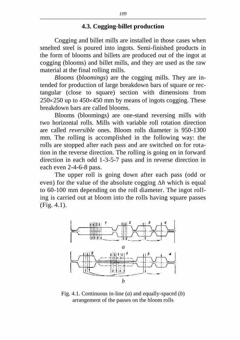
109
4.3. Cogging-billet production
Cogging and billet mills are installed in those cases when
smelted steel is poured into ingots. Semi-finished products in
the form of blooms and billets are produced out of the ingot at
cogging (blooms) and billet mills, and they are used as the raw
material at the final rolling mills.
Blooms (bloomings) are the cogging mills. They are in-
tended for production of large breakdown bars of square or rec-
tangular (close to square) section with dimensions from
250250 up to 450450 mm by means of ingots cogging. These
breakdown bars are called blooms.
Blooms (bloomings) are one-stand reversing mills with
two horizontal rolls. Mills with variable roll rotation direction
are called reversible ones. Bloom rolls diameter is 950-1300
mm. The rolling is accomplished in the following way: the
rolls are stopped after each pass and are switched on for rota-
tion in the reverse direction. The rolling is going on in forward
direction in each odd 1-3-5-7 pass and in reverse direction in
each even 2-4-6-8 pass.
The upper roll is going down after each pass (odd or
even) for the value of the absolute cogging h which is equal
to 60-100 mm depending on the roll diameter. The ingot roll-
ing is carried out at bloom into the rolls having square passes
(Fig. 4.1).
Fig. 4.1. Continuous in-line (a) and equally-spaced (b)
arrangement of the passes on the bloom rolls
a
b

110
The square passes are often called box grooves. The roll-
ing directions and the quantity of passes in each groove are
shown by the arrows. For production of square section blooms
the breakdown bar is moved by special rulers (manipulators)
along the roll barrel from one box groove into another having
smaller cross section. The breakdown bar is turned over (turned
around the longitudinal axis for 90º) before rolling in the next
groove. The total quantity of the passes at bloom has to be odd
and is of 9-17 passes.
Billet mills are used for bloom rolling into the semi-
finished products of smaller sections from 6060 up to
170170 mm, which are called billets. It is inexpediently to roll
sections less than 250250 mm at bloom, because its efficiency
is sharply decreased due to the increase of quantity of passes.
The usage of billet mills permits to increase the final section of
blooms and to enlarge its efficiency. The possible efficiency of
blooms with 1300 mm rolls is about 6 million tons per year.
Continuous-billet mills (CBM) are used at modern metallurgi-
cal plants with the big production volume of section products.
They are installed immediately after bloom and work without
intermediate blooms heating. In case of production of a large
volume of large size round billets with diameter 90-350 mm,
tube-billet mills (TBM) are installed after bloom where the
square billet is also rolled. Continuous billet cast machines are
highly widespread at present what allows to exclude the usage
of blooms and billet mills.
Continuous-billet mill consists of 14 irreversible two-roll
stands with individual roll drive. Only one pass is accomplished
in each stand. The stands are combined in two groups. There
are 8 stands in the first group, two of them with 900 mm diame-
ter of horizontal rolls and 6 stands with 700 mm roll diameter,
4 of these stands with horizontal rolls and two stands with ver-
tical rolls. The second group has six stands with 500 mm roll
diameter. In this group three stands have horizontal rolls and
three stands have vertical ones.
After pouring in steel plants the hot ingots with tempera-
ture 800-900ºC are transported on the rail-way platforms to the

111
department of the heating furnaces of bloom. The ingots are
charged into the furnaces and are heated up to the temperature of
rolling, which is 1260-1300ºC. Heated ingots are extracted out of
the furnaces and loaded on the ingot car. After that they are deliv-
ered along the circle route to the receiving roller conveyor and
transported to the bloom 1300 for rolling. After rolling blooms
are passed to the scarfing machine for removing the surface de-
fects and are delivered to the shears where the defect ends of
bloom corresponding to the head and bottom parts of ingot are
cut. Then the bloom with section 360360 is forwarded by the
conveyor for rolling in stands of the continuous-billet mill. The
billet with section 190190, 170170, 150150 mm is produced
after rolling in the first group of stands, which is sent along the
bypass table to the shears for cutting.
The head end of the ingot (defect) is cut at the shears 7
before rolling in the second group of stands. 150150 mm billet
is used for rolling in the 2nd group. The billet with 125125,
100100, 8080 mm sizes is produced after rolling in the 2nd
group. The system of box (rectangular) grooves is used in the
first group of stands, the system of diamond and square grooves
is used in the second group.
4.4. Continuous casting billets manufacturing
The method of casting with the help of machines for con-
tinuous billet casting is widely used at present. Continuous cast-
ing is intensively introduced in practice in ferrous and non-
ferrous metallurgy replacing pouring into moulds. Up to 90% of
smelted metal is poured by the method of continuous casting in
many developed countries. The major advantage of this method
is the reduction of metallurgical cycle. The necessity of techno-
logical operations of billets casting, removing them from the
moulds, rolling at cogging mills and forging at expensive
equipment is no more relevant. The quality of the produced bil-
lets is much higher due to their homogeneity. The continuous

112
casting provides for the high efficiency and significant increase
of metal yield (for 15% and more) as the result of decrease of
technological wastes during the further processing. The billets
of square and rectangular sections are produced by continuous
casting as well as round shapes and H-sections.
The advantages of the continuous casting are even greater
in the case of combination of continuous casting machine with
rolling mill into one complex, which is called foundry-rolling
plant.
The process of continuous casting (Fig. 4.2) consists in
the following: the liquid metal from the ladle 1 comes to the
heated up to 1200-1300ºC intermediate ladle 2 and from it to
the copper water cooled crystallizer 3 where the dummy ingot
serves as the temporary bottom.
Fig. 4.2. Scheme of continuous billet
casting machine:
1 – ladle with liquid metal; 2 – intermediate
ladle with constant level of liquid metal;
3 – copper water-cooled crystallizer; 4 –
secondary cooling system; 5 – supporting
and pulling rollers; 6 – continuous cast bil-
let; 7 – forming roller; 8 – straightening-
pulling rollers; 9 – moveable device for bil-
let cutting-to-length

113
The solid coating of the billet is being formed in crystal-
lizer. Crystallizer is accomplishing alternate/reciprocal motions
along the axis of the billet to avoid sticking of the coating to the
inner surface of crystallizer. The dummy ingot together with so-
lidified billet is pulled out of crystallizer by the pulling rollers 5.
The metal at the same time is passing the secondary cooling
zone 4 where it is intensively cooled by water up to complete
solidification along the whole section.
At present "S"-type continuous casters became wide-
spread. Their total height is reduced due to the usage of crystal-
lizer and secondary cooling zone bent along the arc of constant
radius.
The machine is equipped by the corresponding devices for
bending and further straightening of the billet. The billet is cut
at the exit by movable device. Modern continuous casters have
from two to four strands, that is the liquid steel is continuously
being fed from the high capacity ladle to two-four crystallizers
behind which the corresponding equipment is installed. The us-
age of multi-strand plants installed after high capacity
steelmaking units (converters, high capacity electric-arc furnac-
es) increases significantly the efficiency of the process.
4.5. Shape and bar production
The types of section mills
Section shapes are conditionally divided into four groups
depending on their size: large shapes, medium-size shapes, light
shapes and rod. Consequently the mills producing these groups of
shapes are divided into heavy section mills, medium section
mills, light section mills, wire mills. Besides there are rail rolling
mills, beam rolling mills or structural mills and strip rolling mills.
The main characteristic of section mills is the rolls diame-
ter. As section mills are multi-stand one, as a rule it is accepted
to indicate the diameter of the rolls in the last finishing stand af-
ter the name of the mill: for example, structural mill 850. The
114
types of the mills and their approximate size range of general
purpose shapes are given below.
1. Structural mills D=800÷850 mm. The following prod-ucts are rolled at these mills:
rails of the broad gauge P43, P50, P65, P75; flanged beams with the height 200÷600 mm (No. 20÷60); channel with the height 200÷400 mm (No. 20÷40);
angles 180180÷230230 mm (No. 18÷23). 2. Heavy section mills D=600÷750 mm. The large shapes
are rolled at these mills: rounds with diameter 50÷100 mm;
square shapes 5050÷100100 mm;
angle shapes 8080÷200200 mm; flanged beams with the height 120÷220 mm (No. 12÷22); channel with the height 120÷220 mm (No. 12÷22); mine rails P15, P18, P24, P33. The weight of one run-
ning meter is indicated by the figures; strip h=14÷50; b=100÷120 mm. 3. Medium section mills D=350÷500 mm. Medium size
shapes are rolled at these mills: rounds with diameter 30÷75 mm;
squares 3030÷8080 mm;
angle shapes 4040÷8080 mm; flanged beams No. 10÷20; channel No. 5÷12; hexagonal steel 20÷75 mm (diameter of inscribed circle); strip h = 45÷60; b =6÷40 mm. 4. Light section mills D=250÷350 mm. Light sections are
rolled at these mills. rounds with diameter 8÷40 mm;
squares 88÷4040 mm;
angle shapes 2020÷4040 mm; reinforcing steel. 5. Strip mills D=300 mm. Strip with 2÷12 mm thickness
and width 200-400 mm are rolled at these mills. The strips are the raw material for welded tubes production.
6. Wire mills D=150÷250 mm. The rods with diameter 5.5÷10 mm are rolled at these mills.

115
The fundamentals of the roll pass design
The cross section of the strip is called the shape.
Section shapes are produced by rolling in the rolls having
on their working surface the cuts or fluting, which are called
grooves. The grooves of two (three) rolls combined along the
vertical axis are forming the pass. The strip section coming
from the pass is taking the form of the pass (Fig. 4.3).
Fig. 4.3. Section roll:
1 – roll barrel; 2 – roll neck;
3 – wobbler
The choice of form and dimensions of the transition sec-
tions, consequence of their arrangement providing for obtaining
the required shape from the given billet production during the
rolling process is called shape sizing and the order of the cho-
sen passes on the rolls arrangement is called roll pass design.
Fig. 4.4. Classification of the passes according with their shape:
standard shape: a – box pass; b – diamond pass; c – hexagonal
pass; d – oval pass; e – round pass; f – square pass;
g – hexahedral pass; flange shape: h – beam pass; i – channel
pass; j – angle pass; k – rail pass; l – tee form pass
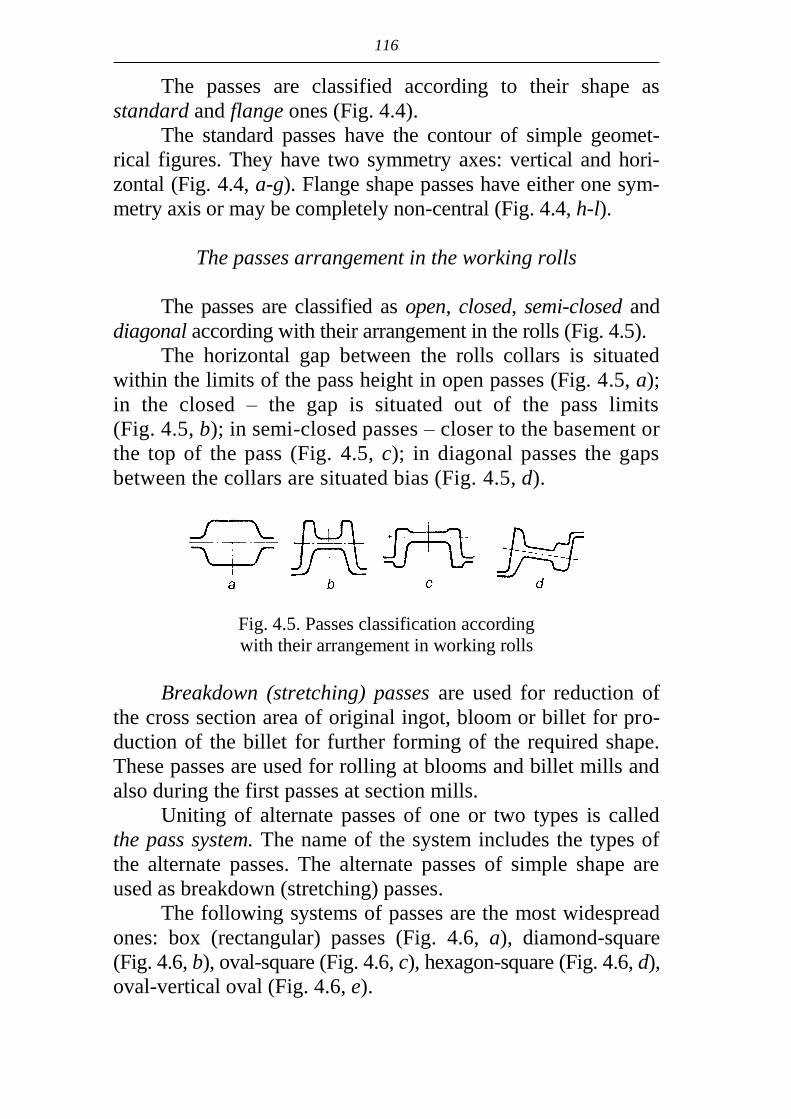
116
The passes are classified according to their shape as
standard and flange ones (Fig. 4.4).
The standard passes have the contour of simple geomet-
rical figures. They have two symmetry axes: vertical and hori-
zontal (Fig. 4.4, a-g). Flange shape passes have either one sym-
metry axis or may be completely non-central (Fig. 4.4, h-l).
The passes arrangement in the working rolls
The passes are classified as open, closed, semi-closed and
diagonal according with their arrangement in the rolls (Fig. 4.5).
The horizontal gap between the rolls collars is situated
within the limits of the pass height in open passes (Fig. 4.5, a);
in the closed – the gap is situated out of the pass limits
(Fig. 4.5, b); in semi-closed passes – closer to the basement or
the top of the pass (Fig. 4.5, c); in diagonal passes the gaps
between the collars are situated bias (Fig. 4.5, d).
Fig. 4.5. Passes classification according
with their arrangement in working rolls
Breakdown (stretching) passes are used for reduction of
the cross section area of original ingot, bloom or billet for pro-
duction of the billet for further forming of the required shape.
These passes are used for rolling at blooms and billet mills and
also during the first passes at section mills.
Uniting of alternate passes of one or two types is called
the pass system. The name of the system includes the types of
the alternate passes. The alternate passes of simple shape are
used as breakdown (stretching) passes.
The following systems of passes are the most widespread
ones: box (rectangular) passes (Fig. 4.6, a), diamond-square
(Fig. 4.6, b), oval-square (Fig. 4.6, c), hexagon-square (Fig. 4.6, d),
oval-vertical oval (Fig. 4.6, e).

117
The square or rectangular
billet is produced after rolling in
breakdown (stretching) passes;
the cross section area of latter
significantly (to 3-5 times) ex-
ceeds the area of the finished
shape.
Pre-leader passes. As usual
the section shapes are rolled of
square or rectangular billet differ-
ing from the form of shaped sec-
tion. Shaped section may be pro-
duced by means of consequent
rolling of the billet in several
passes in which the shape and
sizes of the strip cross section are
changing up to the finished shape.
The reduction of the area
of cross section and stretching
of the strip takes place in the
pre-leader passes. The pre-
leader passes are arranged after
breakdown (stretching) passes at
section mills.
Finishing pass is the last
pass along the rolling process.
The finished shape with the fi-
nal geometry and sizes is com-
ing out of it.
The last pre-leader pass previous to finishing pass is
called pre-finishing or the leader pass. They differ regarding the
shape and sizes from the finishing passes insignificantly. The
degree of the finishing pass filling and the size of the finished
shape depend on the shape and the sizes of pre-finishing pass.
The arrangement of the listed types of passes in the general
scheme of the passes is given on Fig. 4.7 by the example of an-
gle shape rolling.
Fig. 4.6. The system of
breakdown passes:
a – box (rectangular); b –
diamond-square; c – oval-
square; d – hexagon-square;
e – oval-vertical oval

118
Fig. 4.7. Scheme of the angle steel rolling
Shapes production
The special rail-beam (structural) mills are used for roll-
ing of the rails of the broad gauge P43, P50, P65, P75, heavy
beams No. 20÷60 and channel No. 20÷40.
The working stands are arranged in two lines. The cog-
ging stand, the reversing one, the two-roll stand with rolls di-
ameter 950 mm (small bloom) are situated on the first line. Two
roughing stands and three-high stands with common roll drive
from one motor and one finishing two-roll irreversible stand
with individual roll drive are situated on the second line.
The blooms with section 250250-320320 mm are used
for rail rolling which are heated up to the temperature
1180-1200ºC in continuous furnaces. The heated blooms are
rolled in reversing stand for 5-7 passes in box and channel
passes. After that the unrolled metal (process work–piece) is
continuously rolling in the first and second roughing three-high
stands with rail passes. The last pass is being accomplished in
the finishing pass (Fig. 4.8).
The first four passes are called tee-shape ones. The rail
flange is being formed in them during the rolling of rectangular
billet. The process work-piece after tee-shape passes comes to
so-called slitting rail pass (the fifth on Fig. 4.8). The elements
of the rail are being formed out of tee-shape section in the slit-
ting pass, namely head, neck and flange. After the slitting pass

119
Fig. 4.8. The sizing scheme for rails rolling
the rolling is going in the pre-leader rail passes (6th, 7th and
8th) where the gradual rail forming takes place. The last pass
along the flow of the rolling is called finishing one. The
finished 75 m rail comes from it. The rail is being cut by the
shuttle saws (6) to 25 m measured lengths. After that the rails
are marked, and then they are bent for flange to reduce the warp
during cooling on the cooler. In case the rails are not bent
previously it might happen that they will be bent for the head
after cooling.
The rails are taken from the cooler at 600ºC and sent to
isothermal furnaces where they are kept for 2 hours at 600ºC
for prevention of flakes appearance which are the main defect
during the process of rail manufacturing. After getting cold the
rails are entering the rail finishing department where they are
straightened at roller straightening machines and presses, and
the rails ends are milled. Three holes from each end of the rail
are drilled for their joining. To increase the wear resistance of
the rail head it is quenched. The quenching of the rail ends and
the volumetric quenching is used.
The universal stand is installed instead of finishing two-
high stand for rolling of beams and channels.
Flanged beams No. 10÷20, channels No. 10-20, equal-
sided angle steel No. 8-16, L-bars No. 8/5-8/11, round with di-
ameter 50-120 mm, square 50-100 mm, strips with thickness
14-50 mm and width 100-200 mm, steel mine timbering 18A,
18B, 28A and 28B, the rails of narrow gauge and other shapes
are produced at semi-continuous large section mill 600.
120
The mill consists of 17 working stands arranged in three
parallel lines. There are two groups of continuous stands in the
first line between which the conveyer roller-hearth maintaining
furnace is installed. The stands are arranged continuously in-
line at the distance enough for the process work-piece placing
in the second and third lines. The transfer of the process work–
piece between the lines is accomplished by transfer mechanism.
The last 17th stand used for beams and channels rolling may be
replaced with universal stand.
The raw material is bloom with 300300 mm section,
length from 5.5 up to 6 m produced at bloom 1150. Three heat-
ing furnaces with capacity 110-120 tons per hour each are used
for bloom heating.
The installations for hydraulic and steam de-scaling are
provided for ensuring the good surface of the finished sections.
The turners are installed before the stands, the hot shears with
the cutter load of 8 MN for dividing the process work–pieces
into parts are installed behind the conveyer furnace.
All stands are being set in motion from the individual en-
gines. The speed of the process work-piece exit out of the last
stand is 10 m/sec. One stationary and nine movable drop saws
with discs having diameter 1800 mm are installed for shearing
the finished strip to lengths from 6 up to 24 m.
After cutting the strips are being fed to the coolers. There
are altogether four coolers located in pairs with the length 44 m
and width 24 m each. Each cooler at the width consists of two
sections with the length 12 m, which can work conjointly or in-
dependently of one another.
Four lines of cold finishing section are connected between
themselves by roll-tables. Each line is equipped by movable
straightening machine, cold saw, rope transfers, section stackers
and other machines providing for the complete mechanization
of finishing, handling and packing the finished products.
Semi-continuous medium-section mill 350 consists of 15
two-high stands located in three parallel lines. 10 stands are
installed in the first line. The first stand is installed separate-
ly, it is followed by the first six-stand group including three

121
horizontal and three vertical stands. The first group is fol-
lowed by the second three-stand continuous group, the inter-
mediate stand has the vertical rolls.
Crank drop flying shears are installed at the exit from the
first continuous group for cutting the process work-piece’s
leading end before feeding into the second continuous group.
The process work-piece is tilted before feeding. Two separately
standing horizontal stands are installed in the second line; the
third continuous group of stands is installed in the third line, the
first stand is vertical, the others are horizontal. The billets with
150150, 160160 mm section are being heated in four contin-
uous furnaces with end fit and discharge. The shears are in-
stalled in front of the first stand for cutting the leading end in
case of need and dividing the billet in half. The strip is deliv-
ered from one line to another along the repeaters during the
process of rolling.
The maximum speed of rolling in the last stand is 15
m/sec. The process work-piece is being cut into parts by flying
shears after rolling according to the length of cooler. The fin-
ished steel is moving along the roll-table and is directed with
the help of regulating mechanism to one or another side of the
double racking type cooling bed, it is straightened then and cut
to measured lengths. Shaped and large sections are cut by pro-
filing tool or by saws. The following sections are rolled at the
mill: round 35-65 mm steel, rebars No. 36, 40, angle steel equi-
lateral and non-equilateral with the length of flange from 45 up
to 90 mm, flanged beams and channels No. 10.
Double-strand small-section mill 250 (Fig. 4.9) includes
the continuous seven-stand roughing group (7) equipped by hor-
izontal duo-stands and two continuous finishing groups of stands
(9), consisting of eight alternate stands each – vertical and hori-
zontal duo. The mill is equipped by safety flying shears located
in front of the roughing group (6) and behind it (8) for cutting
the process work-piece’s leading end and safety shear for the
process work-piece cutting during the buckling in the finishing
group. The flying shears (10) for dividing the process work-
piece into lengths corresponding to the length of the cooler
(125 m) are installed in each line behind the finishing groups.

122
Fig. 4.9. Layout of continuous small-section mill 250:
1 – charging grid; 2 – inlet roll-table; 3 – heating furnace;
4 – pusher; 5 – distributing device; 6 – shears; 7 – rough-
ing group of stands; 8 – flying shears; 9 – finishing
groups of stands; 10 – cooler; 12 – reels (coilers); 13 –
coil transporter; 14 – coil conveyor
In the roughing group of stands the rolling is realized in
two strands (two billets) simultaneously. One strand (one billet)
is rolled in each finishing group.
8080 mm section and 5-11.7 m length billet is heated
in continuous furnace with side loading and unloading. Dis-
tributing device delivers the billets unloaded from the furnace
in turn along two parallel lines of rolling into the roughing
group. It is possible to accomplish two technological schemes
of cooling and finishing. The first scheme is the work to the
reels with winding of round sections with diameter 18-20 mm
in four reels (12). The wound coil is pushed to the transporter
(13), then it is delivered to the hook conveyor (14) for cool-
ing, after that the coil is bundled and delivered to the stock of
the finished products by means of stripper and bundling ma-
chine. The second scheme is the work to cooler. In this case
the process work–piece is cut to lengths corresponding to the
cooler length after finishing stand and is delivered to two-
sided cooler (11). The cooled strips are straightened on
straightening machines, they are cut then by cold sheares to
measured lengths, gathered and bundled.
The round 10-24 mm steel, 16 mm square steel, angle
steel with flange 25-40 mm and strip steel is rolled at this mill.

123
Wire mills
The rods are rolled to the large mass coils from 200200 mm
section billet with the speed up to 100 m/sec. at modern wire
mills with capacity up to 1 million tons per year. These speeds
are possible due to the usage of finishing and pre-finishing units
including from four to ten (arranged with 120º angle to each
other) three-roll or two-roll stands. The rolls having the over-
hanging discs type with diameter 150 mm are made of tungsten
carbide. The discs are arranged with the 45º angle to the hori-
zontal line and the axis of each next pair of discs – with the 90º
angle to the previous axis.
The continuous wire mill 150 is used for rolling rods of
high carbon and alloyed steel in coils with mass equal to 2 tons
(Fig. 4.10).
Fig. 4.10. Layout of continuous wire mill 150:
1 – walking beam heating furnace; 2 – scarfing machine;
3 – thermo-milling machine; 4 – cogging group of stands;
5 – flying shears; 6 – duplex roller furnace; 7 – break-down
group of stands; 8 – shears; 9, 10 – the first and the second in-
termediate groups of stands; 11 – finishing stand blocks;
12 – two-stage cooling devices; 13 – wire wraps collectors and
coil compactors
The incoming billet with 200200 mm section is rolled
after heating in walking beam furnace in cogging group of
stands where the scarfing is made by two thermo-milling ma-
chines from four sides. The process work-piece after heating in
pusher-type duplex-roller furnace up to 1200ºC is rolled in two
strands in break-down and the first intermediate group and in
one strand in two second intermediate groups and two finishing

124
blocks (ten stand ones). The speed at the exit is equal to
60 m/sес. The rods are passed two-stage cooling. The process
work-piece is cooled in tubes by high pressure water (2 MPa)
up to 630ºC at the first stage. The process work-piece is laid by
special device named laying head on the traveling conveyer in
the form of the loose-wounded strands by means of tube carrier
(Fig. 4.11).
Fig. 4.11. Layout of two-stage regulated
rod cooling device:
1 – last finishing stands of the wire mill; 2 – tubes for wa-
ter cooling of rod; 3 – conductor pipe; 4 – the drive of
tube carrier rotation; 5 – tube carrier; 6 – transporter; 7 –
ventilator; 8 – scattered coil annular wraps of the hot rod;
9 – cone plugs on the turn-table for coil forming
At the end of transporter the rod cooled up to 300ºC is de-
livered to the coils packer where the laps are gathered again in-
to the coil, which is compressed by hydraulic press and deliv-
ered to the finger conveyer.
At present the new rolling mills have been produced with
the rolling speed up to 120 m/sес.
4.6. Sheet production
Classification of the sheet rolled products
All the sheet rolled products are divided depending on the
thickness into two main categories: thick plates with thickness
4 mm and more; thin sheets with thickness less than 4 mm.
125
The sheet rolled products are classified according to many
features.
Depending on the width of plates:
wide strip with 600-700 mm width and more. Maximum
width of the rolled strip is 2300-2500 mm. The mills
where the wide strip is rolled are called wide strip roll-
ing mills;
narrow strip with less than 600-700 mm width. Strip
with the width less than 300 mm is called band.
Depending on the chemical composition the following
steels are distinguished:
carbon steels: low-carbon (C up to 0.3%); medium-
carbon steels (C up to 0.6%); high-carbon steels (C up to
1.5%);
alloyed steels (the alloying components are Cr, Si, Ni,
Mn, Mo, V); low-alloyed ones with alloying compo-
nents (up to 4%); medium-alloyed (up to 10%); high-
alloyed (up to 45%).
Regarding the purpose steels are classified as follows:
structural steels (carbon and low-alloyed);
corrosion-resistant (stainless) steels. They have a great
content of Cr and Ni or only Cr in their composition;
electric steels(dynamo and transformer). They have a
great content of Si (1.0-3.5%) and very low content of C
(less than 0.01%). Electromagnetic properties of these
steels are improved due to increase of Si content and de-
crease of C content.
Regarding the methods of rolling they are distinguished as
follows:
hot rolling of plates;
hot rolling of sheets and strips;
cold rolling of thin strips.
Production of plates
The following products are produced at plate mills:
plates with thickness h=4-50 mm; width b=200-1050 mm;
length l=5-18 m;

126
plates (armor) with thickness h=50-380 mm; width
b=600-5000 mm; length up to 28 m.
The plates with h=50-380 mm are rolled of flat square in-
gots. The mass of ingots may exceed 100-250 t.
The sheets with the thickness less than 50 mm are rolled
of slabs. Slab is the flat rectangular section ingot with ratio of
width and thickness b/h=3-12.
Slabs may be rolled and cast at continuous casting ma-
chine. Rolled slabs are produced by rolling at cogging mills –
slabs or blooms. The thickness of the rolled slabs is h=100-300,
width b=600-2500 mm, length l=1.5-14 m. The mass of slab
exceeds 10-14 t.
Slabs with thickness h=80-250 mm are cast at continuous
casting machine. Casting at continuous casting machine is con-
sidered to be the most contemporary method of slab production.
Replacement of slabs with continuous casting machines
decreases the production price up to 8%, increases the efficien-
cy up to 7-8% and metal yield on average up to 8-12% for car-
bon steels and up to 15-20% for alloyed steels.
The types of mills for plates rolling
Two types of mills are used: one-stand and two-stand
mills.
One-stand mills. Reversible four-roll mills are considered
to be modern ones. They have two working rolls and two back-
up rolls, which diameter is greater than that of working ones.
The backup rolls decrease the bending of the working rolls.
Four-roll mills are called quarto mills.
The maximum size of the working rolls at these mills is
Dw.r=1200-1400 mm, backup rolls Db.r=2000-2400 mm. The
rolls barrel length is up to Lb=5500 mm. One-stand mills are
used for rolling sheets and plates with thickness h=20-250 mm
and width up to 5500 mm.
Two-stand mills with in-line arrangement of stands. The
distance between the working stands is greater than the length
of the process work-piece coming from the first stand with in-
line arrangement of stands. The first stand along the rolling

127
direction is called a break-down one and the second is called
the finishing one.
Reversible two-roll stands (duo-stands) or reversing four-
roll stands (quarto-stands) are used as the break-down stands at
modern two-stand mills.
Reversible stands quarto or reversing universal quarto
stands are used as finishing stands. The universal working
stands have horizontal rolls as well as vertical arranged rolls,
which are used for cogging the sheet edges.
The biggest two-stand mills have the quarto stands with
working rolls Dw.r.=1000-1200 mm, backup rolls Db.r=2000-
2200 mm and the roll barrel length up to Lb=4800 mm.
Two-stand mills have the higher efficiency and the better
quality of surface if to compare with one-stand mills. The stand
with vertical rolls Dv.r.=900-1100 mm is installed at plate mills
(one- and two-stand mills) in front of the first working stand.
This stand is used as de-scaling mill for removing the furnace
scale from the surface of slab (ingot). The scale is loosened and
then it is removed by water descaling.
Technological operations during plates rolling
Technological process includes the following main op-
erations.
Preparation of ingots or slabs for rolling. It includes in-
spection of the surface and removing of surface defects (skins,
blisters, cracks, non-metallic inclusions etc.).
Heating of slabs and ingots. Slabs and small ingots are
heated in continuous furnaces with the walking beams. The
large ingots are heated in chamber traveling-hearth furnaces.
The temperature of heating before rolling depends upon the
chemical composition of the metal and amounts as usual to
1150-1280ºC. The heated slabs (ingots) are delivered to the
roll-table one by one and transported to the mill for rolling.
Descaling of the slab (ingot) surface before rolling. The
scale breaker with vertical rolls is installed with this purpose in
front of the mill (one-stand or two-stand). The heated slab
comes first to scale breaker. The scale is loosened due to the

128
side cogging and its removing from the surface is made easier
with water jet under the high pressure (water descaling). Une-
venness of slab width and side taper of ingot is eliminated sim-
ultaneously.
Rolling. All breakdown and finishing passes are accom-
plished in one stand at one-stand mill. The total quantity of
passes has to be odd. The process work-piece is returned to the
scale breaker after the second and the fourth passes for remov-
ing the side camber by the vertical scale breaker rolls. Two
slabs are being rolled simultaneously at two-stand mills: one in
breakdown stand and the second in finishing stand. Slab is
rolled first in breakdown stand. The process work-piece is re-
turned to the scale breaker after the second and the fourth pass-
es for removing the the side camber. The number of passes in
breakdown stand amounts to 5-11. The process work-piece is
delivered to the finishing stand for further rolling after finishing
of rolling in the breakdown stand. The next slab is fed to the
breakdown stand at the same time. The further rolling is going
on simultaneously in breakdown and finishing stands. The
number of passes in finishing stand amounts to 5-9. The regime
of deformation in breakdown and finishing stands is calculated
in such a way that the time of rolling in these stands would be
equal. In this case the efficiency will be higher.
The straightening of the sheets. The sheets are straight-
ened in the hot state at the surface temperature equal to
700-750ºC at roller straightening machines (7-13 rollers). The
sheets with thickness more than 50 mm are straightened in the
cold condition at hydraulic presses.
Cooling of sheets and their lay-out. The sheets are
cooled after straightening on the coolers of the following
types: roller one with washers, with walking beams, link-and
chain transfer type.
The inspection of the sheet surface from two sides takes
place after cooling on the inspection tables where the uncovered
surface defects are marked for their further removing.
The layout of the sheet is being made from all four sides.
Cutting of the sheets. The cutting of the leading end and
sheet trailer with thickness of sheets from 25 to 50 mm is

129
accomplished at guillotine shears (cutting to length). Side-lay
edges are cut at guillotine shears also (longitudinal cutting).
The strip ends cutting is accomplished by guillotine shears for
strip cutting to length with thickness up to 25 mm. The edges
are cut by circular shears. The plates are cut by flame cutter.
Heat treatment of the sheets. It is made for metal structure
and mechanical properties improvement. The following kinds
of treatment are used: normalization, annealing, tempering,
temper hardening. The sheets are straightened in cold condition
after heat treatment.
Production of sheets at two-stand plate mill 2800
The length of the roll barrel is the main characteristics of
the plate mills. The figures (number) following the name of the
mill indicate the length of the rolls barrel. Thus the name "plate
mill 2800" indicates that this mill has the length of the roll bar-
rel equal to 2800 mm.
The layout of equipment of two-stand plate mill 2800 is
given on Fig. 4.12.
Fig. 4.12. The typical layout of two-stand plate mill 2800:
1 – continuous heating furnaces; 2 – stand with vertical
rolls; 3 – breakdown reversing stand duo; 4 – finishing
reversing universal stand quarto; 5 – roller-straightening
machines; 6, 6a – cooling tables; 7 – inspection tables
with tilter; 8 – dimensioning trolleys; 9 – guillotine shears
of cutting to length; 10, 11 – circular guillotine shears;
12 – gathering pockets; 13 – separate standing guillotine
shears; 14 – heat treatment furnace for plates

130
The mill is used for rolling plates with thickness 4-50 mm,
width up to 2500 mm, length up to 20 m.
The starting ingot for plate rolling is a slab with thickness
125-250 mm, width 700-1600 mm, length 2500-6000 mm.
Slabs are heated in three continuous furnaces 1. The roll-
ing mill includes the rough scale breaker with vertical rolls 2,
the roughing two-roll stand 3 and finishing universal four-roll
stand 4 (quarto stand). All stands are reversing ones. The roll
dimensions are as follows: in stand 2 D=950-1000 mm, the
length of the roll barrel Lb=600 mm; in roughing duo stand 3
D=1100 mm, Lb=2800 mm; in finishing universal stand 4 the
diameter of the working rolls is Dw.r=800 mm, the diameter of
backup rolls is Lb.r=1400 mm, the length of the rolls barrel is
Lb=2800 mm.
The slabs heated in the furnace are delivered by the roller
table to the scale breaker. Slab is rolled first in rougher for sev-
eral passes and then in finishing stand. The quench is installed
after the finishing stand for cooling plates by air-water mixture
for obtaining the fine grain structure of the metal and high me-
chanical properties. After rolling plates are straightened in roll-
er straightening machines 5. The first straightening machine is
used for hot straightening of sheets with thickness from 4 to 25
mm, the second one is used for straightening of sheets with
thickness 25-50 mm.
Sheets cooled on the cooler 6 sheets are delivered to the
second technological line of the mill and then through the cool-
er 6a – to the third line. The sheets are inspected here on in-
spection table 7 and laid by means of special trolley 8. Cutting
of sheets to length takes place on guillotine shears 9 and the
side trimming – on the circular shears 10.
The side trimming of rolled sheets with the thickness
more than 25 mm is made on longitudinally arranged guillotine
shears 11; with this purpose sheets are delivered from the third
line back to the second line. The finished sheets are gathered in
the pockets 12.
The additional cutting may be arranged at separate stand-
ing shears 13. The furnace 14 is used for heat treatment of the
products.

131
Hot rolling of the light sheet steel
At present 50-70% of light sheet steel is produced at strip
rolling mills. The products manufactured at continuous mills
are characterized by high quality of the surface and high preci-
sion. The annual capacity of continuous wide-strip hot rolling
mills exceeds 4.0-6.0 million tons.
Due to the high efficiency and high level of mechaniza-
tion and automation the finished product price is significantly
lower than the price of products produced at the other strip
mills.
Continuous wide-strip mill 2000
The layout of the modern continuous wide-strip mill 2000
is given on Fig. 4.13.
Fig. 4.13. Layout of continuous wide strip mill 2000:
1 – heating furnaces; 2-5 – working roughing stands;
2 – vertical roughing two-roll stand scale breaker; 3 – two-
roll stand; 4 – universal four-roll stand; 5 – continuous
three-stand sub-group of universal four-roll stands; 6 – in-
termediate roller table; 7 – flying drum-type shears; 8 – the
finishing scale breaker; 9 – continuous finishing group;
10 – collecting quenching roller tables; 11 – 1.2-4 mm strip
reels; 12 – trolley with coil tilter; 13 – 4-16 mm strip reels;
14 – rotary table for coils; 15 – coils conveyer
The mill is used for rolling the coiled steel strip with thick-
ness 1.2-16 mm and width 1000-1850 mm. The cast and rolled
slabs with thickness up to 300 mm, length up to 10.5 m and

132
mass 15-20 t of carbon and low-alloyed steels are used as the
raw material. All stands of the mill are divided into two groups:
roughing (stands 3-5) and finishing continuous (stands 9).
The roughing group consists of one stand with horizontal
rolls 3 and four universal stands with horizontal rolls with diame-
ter Lh.r=1600 mm and vertical rolls with diameter Dv.r=1000 mm
(stands 4 and 5). The feature of this mill is the fact that the last
three stands are combined into continuous sub-group 5 in the
finishing group. It has permitted to decrease the length and to
improve the temperature regime of rolling due to decrease of
heat loss.
The continuous finishing group 9 includes seven four-roll
stands (quarto stands) with diameter of the working rolls equal
to Dw.r=800 mm and backup rolls Db.r=1600 mm. The roughing
scale breaker 2, which provides for the primary breaking of the
furnace scale and formation of the precise dimensions of slab
regarding the width is installed in front of the first stand of the
roughing group. The loosened scale is removed by hydraulic
scaling under the pressure of 15 MPa from the slab surface.
Slabs are heated before rolling in four continuous walking
beam furnaces up to the 1150-1280ºC.
The heated slab is pushed out of the furnace and is deliv-
ered by the roller-table in the roughing scale breaker and than to
the stands of the roughing group. Vertical rolls of the universal
stands are cogging the side edges of the strip avoiding the for-
mation of the side camber and as the result the damage of the
sheet edges during the rolling. After roughing group the strip
with the thickness 30-50 mm is delivered by the intermediate
roller table 6 to the finishing group. In front of the finishing
group the flying shears 7 are installed intended for cutting the
leading end and the strip trailer as well as the roller finishing
scale breaker 8, which is loosens the air scale and by water jets
under high pressure water jets removes it from the process
work-piece surface.
The temperature of the metal at approaching of the pro-
cess work-piece to the finishing group is as usual 1050-1100ºC
and it is 850-950ºC at the exit from the last finishing stand. The
strips are intensively cooled up to the 600-650ºC by quenching

133
in the area from the finishing stand to the reel to reduce the
temperature of the strip during the reeling and to improve the
metal structure of the strip coiled on one of fifth roller-drum
reels. The strip with thickness 1.2-4.0 mm is coiled on the reels
11 and 4-16 mm strip is coiled on the reels 13.
The coiled strip is delivered for rolling to the shop of cold
rolling or to the finishing, which includes the unrolling of the
coils, cutting to length for separate sheets and stacking or slitting
of strip to separate bands, which are coiled into the bundles.
Foundry-rolling complexes (units)
The success in production of modern continuous casting
machines (CCM) with high level of automation and managing
together with the achievements in smelting of fine steel, avoid-
ing its dirt during the continuous casting as well as metal de-
fects during crystallization has permitted to deliver the cast bil-
let without inspection to the continuous mill (direct rolling) re-
taining the casting heat. The possibility of combination of con-
tinuous casting and hot rolling into one unit called foundry-
rolling complex (FRC) has appeared.
The main complexity in creation of FRC is concluded in
the power difference of CCM and rolling mill. FRC for produc-
tion of light hot rolled strip of continuous cast slabs obtained
the industrial development.
The main technological schemes of FRC for production of
hot rolled strip is given on Fig. 4.14.
The technology of the sheet production from thick slabs is
presented on Fig. 4.14, a. Slabs after casting on CCM are cut by
shears 2 and delivered after quality inspection to the heating
furnace of the rolling mill. In this case the heat of the hot fit of
slabs is partially used. The cutting of the slab strip after casting
permits to run the process of casting and rolling of slabs inde-
pendently. This scheme is similar to the standard scheme of
sheet production at continuous wide-strip rolling mill.
FRC with the light slab technology of light hot rolled strip
production (CSP process) is given on Fig. 4.14, b. The casting
of light slabs (with thickness 50-90 mm) permitted to increase

134
Fig. 4.14. The development of the technological schemes
of FRC for production of flat hot rolled strip:
a – slab technology; b, c – light slab technologies, CSP
and ISP accordingly; 1 – CCM; 2 – shears; 3 – quality
inspection; 4 – furnace; 5 – coil box; 6 – roughing mill;
7 – continuous mill; 8 – Steckel mill; 9 – cooling de-
vice; 10 – reel
the casting speed and to reduce significantly the number of
stands in the line of the rolling mill excluding or significantly
decreasing the number of stands in roughing group. The process
of casting and rolling are being accomplished in uniform
technological line. The slab strips are delivered for heating into
the long (up to 200 m) tunnel oven 4 after cutting by shears 2.
This oven is the buffer between the CCM and rolling mill
presenting the continuous finishing group of stands.
The feature of the scheme given on Fig. 4.14, c (ISP tech-
nology) is the casting of the light sheet slab using the cogging of
ingot with the liquid core in roller guides of CCM as well as in
roughing stands quarto (2-3 stands) installed just at the exit of
CCM. It permits to produce the strip with thickness 15-20 mm,
which is being reeled into coil by the reel in reheating furnace 5
(coil-box). The following rolling permits to produce thin hot
rolled strip in the finishing group of stands 7 or at Steckel mill 8.

135
The usage of the processes of the direct strip casting caus-
es great changes in production of hot- and cold rolled strip.
The scheme of steel pouring into the rolls located under
the pouring ladle is given on Fig. 4.15. The liquid steel contact-
ing the cooled rolls is crystallizing. The cogging of the metal
takes place in two-phase state (soft cogging) that is the continu-
ous casting is combined with the rolling within one unit. Run-
out of the melt from the ends of the roll is prevented by the side
seals. The fast consolidation during the strip casting decreases
micro-segregation and provides for more fine distribution of in-
clusions, as the result the quality of the metal is improved.
Fig. 4.15. Layout of the roll type foundry-rolling unit
The thickness of strip is usually 1.5-5.0 mm at this method
of casting. The strip is run-out of the rolls with the temperature
about 1300ºC. The in-line installation of the rolling stands for
production of especially thin strip is possible. The short length,
the moderate investments and production flexibility are the most
important advantages of two-roll casting-rolling units.
Cold rolling of thin strip and sheets
The process of cold rolling is more power-consuming if to
compare with the hot rolling process. The metal is being hard-
ened, becomes hard-to-deform during the cold rolling and re-
quires the additional energy consumption for restoration of
plastic properties, that is for accomplishing of annealing.

136
Besides the technological process of cold rolling is more
complicated in comparison with the hot rolling and includes the
whole series of additional operations requiring the usage of
complex and various equipment such as continuous pickling
lines, annealing devices for metal hardening, tempering mills,
shearing units for sheets and strip, units for protective coating
application etc.
However the cold rolling has many advantages if to com-
pare with the hot rolling:
the possibility to produce thin and especially thin strip
and sheets with thickness less than 0.8-1.8 mm up to
several microns 0.002-0.003 mm;
high quality of the surface of strip and sheets, high pre-
cision of geometry. It is possible to produce by the pro-
cess of cold rolling the sheets with any degree of rough-
ness from mate to mirror due to the special treatment of
the rolls surface;
the possibility to produce cold rolled strip with required
physical-mechanical properties.
The wide usage of cold rolling was determined by these
advantages.
At present the share of cold rolled sheets in the total mass
of thin sheets amounts to 50% approximately. The following
goods are produced by cold rolling: automobile sheets with
thickness 0.25-2.5 mm; sheet iron with thickness 0.38-0.80 mm;
tin with thickness 0.16-0.36 mm; foil with thickness 0.001-0.005
mm as well as the rolling of corrosion resistant (stainless) steel
and electric steel – dynamo steel and transformer steel.
The range of cold rolled sheet products is as follows:
sheets with thickness 0.2-0.4 mm, width – 510-2300 mm,
length from 1200 up to 5000 mm; strip in coils with thickness
0.2-4.0 mm, width – from 200 up to 2300 mm; bands in coils
with thickness 0.05-3.6 mm and width up to 600 mm.
The types of mills for cold rolling of thin strip and sheets
Two types of mills are used:
one-stand reversing mills with 4-6-12-20-32 rolls number;

137
continuous mills with 4-5-6 stand number.
One-stand multi-roll reversing mills are used for rolling
of small lots of wide range sheets especially of hard-to-deform
steel grades. The mills setting is simple, the rolling may be ac-
complished with any number of passes. The quarto mills and
20-roll mills are mostly often used in ferrous industry.
Two methods of rolling are used at one-stand mill. The
rolling per sheet is accomplished in quarto stand. The initial in-
got is the hot rolled pickled sheet with thickness 3-10.5 mm; the
final thickness of the rolled sheets is up to 1.5 mm.
The rolling of coiled strip is accomplished at 20-roll mills
with working rolls diameter Dw.r.=3-150 mm and the length of
the barrel Lb=60-1700 mm.
The thin strip with the thickness 0.57-0.60 mm and
width up to 1700 mm is included to the range of these mills.
The initial billet is pickled hot rolled coil strip with thickness
3-4 mm. The initial billet for rolling the bands with thickness
0.002-0.10 mm is cold rolled strip with thickness 0.03-1.0 mm
passed the bright annealing.
One-stand reversible mills are equipped by reels from the
front and back side. The rolling is being accomplished for sev-
eral passes rewinding the strip from one reel to another with
high tensions of the strip between the reels and the working
stand with compulsory use of technological lubricants for re-
duction of influence of friction forces on the rolling force. The
scheme of 20-roll mill of cold strip rolling is given on Fig. 4.16.
Fig. 4.16. Layout of 20-roll mill for cold strip rolling:
1 – working rolls; 2 and 3 – intermediate and backup
rolls; 4 – strip thickness gauge; 5 and 7 – tension de-
vices; 6 – strip; 8 – reels’ drums

138
The mill has only two working rolls deforming the strip.
The rest of the rolls are backup ones and are used for reduction
of the working rolls bend. The continuous mills for cold rolling
of thin strip are used for production of large volumes of rela-
tively small strip range. The modern continuous mills consist of
5-6 irreversible stands quarto and the strip is located in all
stands simultaneously. Only one pass is accomplished in each
stand. Continuous mills are supplied with de-coiler on the front
and the reel at the back side.
Hot rolled coils pickled in advance with lubricated surface
serve as the strip plate for continuous cold rolling mills. Hot
rolled coil strip is received from the continuous wide-strip hot
rolling mills. The thickness of the strip plate is 2-6 mm depend-
ing on the thickness of the finished product.
The great pressure of metal on the rolls during the cold
rolling originates due to the metal hardening in the process of
deformation and a great influence of outside friction forces.
The cold rolling of the coil strip is being accomplished with
significant tension of the strip between the stands and be-
tween the last stand and the reel with compulsory usage of
technological lubricants. The strip tension provides for signif-
icant reduction of metal pressure on the rolls and permits to
roll the strip with high reductions per each pass and contrib-
utes to tight reeling of the strip on the reel and its steady posi-
tion between the rolls, the strip is not displaced along the roll
barrel. The usage of technological lubricants causes the re-
duction of the influence of the friction forces and reduction of
the metal pressure on the rolls.
The strip with thickness 0.2-3.5 mm is rolled at 5-stand
continuous mills and strip with thickness 0.18-1.0 is rolled at 6-
stand mills. The width of the strip rolled at these mills is up to
1200 mm.
Two methods of rolling are used at continuous mills: in-
dividual coil rolling and endless rolling of coil strip. The pick-
led hot rolled coils are delivered from stock by crane to the
conveyer in front of cold rolling mill and after that one after
another the coils are delivered to the decoiler at individual coil
rolling. The arm with electromagnet is going down, the magnet
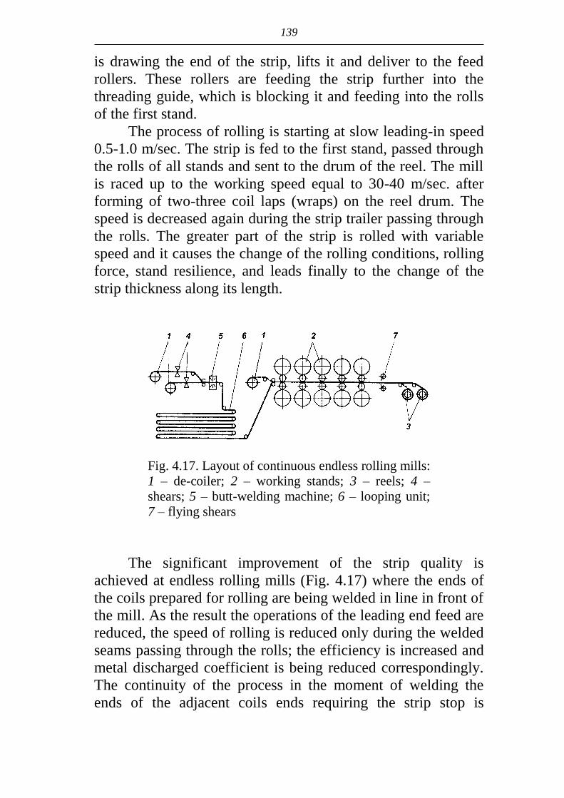
139
is drawing the end of the strip, lifts it and deliver to the feed
rollers. These rollers are feeding the strip further into the
threading guide, which is blocking it and feeding into the rolls
of the first stand.
The process of rolling is starting at slow leading-in speed
0.5-1.0 m/sec. The strip is fed to the first stand, passed through
the rolls of all stands and sent to the drum of the reel. The mill
is raced up to the working speed equal to 30-40 m/sec. after
forming of two-three coil laps (wraps) on the reel drum. The
speed is decreased again during the strip trailer passing through
the rolls. The greater part of the strip is rolled with variable
speed and it causes the change of the rolling conditions, rolling
force, stand resilience, and leads finally to the change of the
strip thickness along its length.
Fig. 4.17. Layout of continuous endless rolling mills:
1 – de-coiler; 2 – working stands; 3 – reels; 4 –
shears; 5 – butt-welding machine; 6 – looping unit;
7 – flying shears
The significant improvement of the strip quality is
achieved at endless rolling mills (Fig. 4.17) where the ends of
the coils prepared for rolling are being welded in line in front of
the mill. As the result the operations of the leading end feed are
reduced, the speed of rolling is reduced only during the welded
seams passing through the rolls; the efficiency is increased and
metal discharged coefficient is being reduced correspondingly.
The continuity of the process in the moment of welding the
ends of the adjacent coils ends requiring the strip stop is

140
secured by the loop accumulator 6. When the process of coils
welding is finished the loop accumulation of strip is produced
again; the strip is cut by flying shears 7 at the exit from the last
stand and is reeled on the reels 3.
Technological operations during the cold rolling
at one-stand and continuous mills
The technological process is accomplished in the follow-
ing succession.
The pickling of the strip is made at continuous units with
the usage of water solution of sulphuric or hydrochloric acid.
Recently the preliminary mechanical removing of the scale
from the hot metal surface before pickling of the latter has been
started.
The considerable part of scale is removed in special in-
stallations where strip is processed by steel or iron shot simul-
taneously from two sides. The strip is subjected to acid pickling
after mechanical processing. The combined method of cleaning
provides for reduction of metal loss during descaling up to 1%
instead of 2%, besides the installation occupies considerably
smaller area.
Hot rolled strip, which is covered by scale after cooling, is
the initial billet for cold rolling.
It will be pressed into the metal making the surface quali-
ty worse if not to remove it.
Cold rolling. The coils are lubricated and delivered for
rolling after pickling. The total reduction during the cold rolling
at 5 stand mill is 50-80%.
The annealing of coils is made for relieving of strengthen-
ing (cold-hardening) during cold rolling. The higher the defor-
mation degree is, the more strengthened becomes metal, and its
plasticity is reducing. The re-crystallization annealing at 650-
730ºC is used for renewal of plastic properties. Annealing may be
final when the rolling is accomplished and intermediate one be-
tween the stages of cold rolling. In case the significant defor-
mation has to be produced during the cold rolling it is usually di-
vided to several stages with intermediate annealing. The bell-type

141
furnaces or continuous annealing units are used for annealing the
developed strip. The annealing is made in protective gas medium
(90-97% of nitrogen and 3-5% of hydrogen).
The temper rolling. It is the cold rolling with relatively
small 0.8-1.5% reductions. The temper rolling is used after roll-
ing and annealing are finished and it is the final operation of
cold rolling.
Cold rolled sheets are after used for the subsequent stamp-
ing and applying of protective coatings. The yield lines are being
formed on the surface, it becomes roughly uneven and the so-
called orange skin (peel) is formed during the stamping of an-
nealed cold rolled plates without tempering. This surface is of
little use for applying of coatings as well as for enameling. The
surface layer is only strengthened during tempering, the inner
layers remain the plastic ones, non-deformed and the appearance
of plastic shear lines on the surface is being stopped due to this
fact. One- or two stand irreversible mills quarto is used for tem-
pering. The tempering is accomplished for one pass.
The necessary roughness of the strip surface is obtained
during tempering if required. The required degree of roughness
is marked on the rolls for that reason.
Finishing of cold rolled strip. Cold rolled strip is shipped
to the customers as coils or separate sheets. In the latter case
coils are delivered to continuous units for cutting to length
where strip is cut to sheets. The wide strip is slit at slitters to
narrow bands for further reeling into coils.
Protective coatings application is accomplished on strip
and plates for protection in aggressive medium. All kinds of
coatings may be divided into metallic and non-metallic ones.
Tin, zinc, aluminum, chromium, nickel, copper, titanium and
others are used as metallic coatings. Plastics, varnishes, paints
are used as non-metallic coatings.

142
5. TUBE AND PIPE MANUFACTURING
5.1. Tube and pipe range
The range of tubes and pipe is very wide: it includes tubes
with diameter from the tenth part of millimeter up to 2.5 meters
with the wall thickness from hundredth part of millimeter up to
50 mm. Regarding the ratio of diameter to wall thickness (D/S)
tubes and pipe are classified as especially thick-walled tubes
(D/S<5,5), thick-walled tubes (D/S=59), standard tubes
(D/S=920), thin-walled tubes (D/S=2050) and especially
thin-walled tubes (D/S>50).
The following tubes are produced: round, oval, rectan-
gular, square, ribbed, tapered and tubes with variable wall
thickness.
Tube and pipe are widely used in construction of gas- and
oil pipelines, chemical engineering, building projects, compo-
nents of different units and mechanisms.
There are general and special purpose tubes and pipes.
All tubes and pipes are divided into 2 kinds – seamless
and welded – according with the method of production.
Seamless tubes are divided in their turn into hot deformed
(produced by rolling or pressing) and cold deformed manufac-
tured of hot deformed or welded tube billets by means of roll-
ing in cold state at cold-rolling mills and cold-rolling roller
mills (cold-rolled) and cold drawing (cold drawn). Seamless hot
rolled tubes are produced with diameters D=16630 mm and
wall thickness S=1.550 mm.
Tubes with diameter from 25 up to 245 mm and wall
thickness S=2.530 mm are produced by hot pressing. Hot
pressed tubes are often produced of low-plastic hard-to-deform
steel grades.

143
Cold deformed tubes are produced with diameter
D=0.2450 mm and wall thickness S=0.0335 mm.
Welded tubes are divided into electric-welded (D=5÷2520 mm,
S=0.03÷32 mm) and welded in furnaces (D=10÷140 mm,
S=1.8÷5.5 mm).
Seamless tubes take about 40% and welded tubes about
60% in total volume of tubes and pipes.
The comparative analysis of the range and characteristics
of electric welded and hot deformed tubes and pipe shows the
following:
range of diameters of electric welded tubes is wider than
that of hot deformed tubes, but regarding steel grades it
is greatly smaller;
precision of electric welded tubes regarding the wall
thickness is higher than that of hot deformed tubes;
electric-welded tubes can be produced with the smaller
wall thickness if to compare with hot deformed tubes
with equal diameters;
electric-welded tubes produced by pressure welding
have the burr as the result of seam welding salient on the
inner surface up to 0.5 mm (the burr is removed from the
outside surface).
5.2. Seamless hot rolled tubes production
There are several methods of hot rolling of tubes. Each of
these methods includes three operations of plastic working ac-
complished in the following succession:
piercing of solid round billet into thick walled tube
called the shell;
expansion of the shell into rough tube;
sizing or reduction of the rough tube into finished tube
with final dimensions as for diameter and wall thickness.
The piercing of solid round billet into shell is the first
technological operation. The main methods of piercing are
screw rolling and press piercing.

144
The additional installation of elongating mill is necessary in
case of piercing at piercing presses. As to construction that is the
screw rolling mill with fixed plug (similar to piercing mill type).
The shell is produced in two operations. The first is the piercing
of the billet at the press, after which the shell is produced as the
thick walled cup with solid bottom. The second is the rolling of
the cup at elongating mill. The length is increased during the roll-
ing, the bottom is pierced and the shell is produced.
Expansion of the shell into the rough tube. The produced
shell is rolled between the rolls having round grooves and the
plug located inside of the tube. The tube with dimensions close
to the final ones is produced out of shell in the process of reduc-
tion of diameter and wall thickness. These tubes are called
rough tubes.
Two methods of expansion are used for shell expansion
into the rough tube: expansion on short fixed plug (Fig. 5.1, b)
and on movable long mandrel, which is moving together with
the tube in the rolls (Fig. 5.1, a).
Fig. 5.1. The scheme of
tube rolling in the round
groove on movable man-
drel: a – mandrel bar; b –
plug; c – plugless rolling

145
The expansion of the shell into the rough tube on the plug
is accomplished at plug mills and 2-stand tandem mills of
lengthwise rolling. The expansion on the mandrel is accom-
plished at continuous lengthwise mills, pilger mills, three-roll
reelers and rack-type draw benches.
Sizing and reduction of tubes is the final technological
operation for obtaining finished tubes from rough tubes with fi-
nal dimensions as to diameter and wall thickness.
Sizing of tubes is realized at continuous sizing lengthwise
rolling mills with 3-12 stands. The rolling is accomplished within
the system of round passes without any plug (Fig. 5.1, c). The
working stands are irreversible, more often they are 2- or 3-roll
ones. The sizing purpose is to produce the tubes with precise out-
side diameter. It is achieved due to the small reduction of tube as
to the outside diameter to 3-5% in each stand of the mill. Sizing is
accomplished without any tension of tube between the stands.
That is why the thickening of the wall to 4-15% takes place after
sizing. Sizing stands are installed with the inclination by turns to
different sides at 45º angle to the horizon. The neighbor stands
form the 90º angle. Thick walled and especially thick walled
tubes with ratio D/S<12.5 are undergoing sizing.
Reduction of tubes is accomplished at continuous reduc-
tion lengthwise rolling mills in oval grooves without any plug.
Reduction mills are used for significant reduction (decrease)
of the outside diameter of tubes. Decrease of the outside diameter
of tubes is called reduction. The number of stands in reduction
mill is increased up to 28. The 3-roll stands are mainly used.
The rolling is accomplished with tube tension at reduction
mills in contrast to the sizing mills. It permits to increase the
reduction of the tube as to diameter in each stand up to 10-12%
without loss of tube stability (crumbling) and the total reduction
of the outside diameter is up to 75-80%. Besides the rolling
with tension permits to regulate the wall thickness depending
on the value of tension keeping the previous one or reducing it.
The reduction mills installation widens significantly the
range of produced tubes relieving at the same time the main
equipment, where rough tubes are produced. Thin walled tubes
with ratio D/S<12.5 are mainly subjected to reduction.

146
Hot rolled seamless tubes production at tube rolling plants
(TRP) with automatic mill (Stiefel mill)
The main characteristic of the tube rolling mills is the
maximum diameter of the rolled tubes. That is why the number
indicating the maximum diameter of tubes to be rolled is used
after the name of mill: for instance, automatic mill 140.
The plants are divided into three types of sizes depending
on the range of diameters of the rolled tubes: small – TRP-140,
medium – TRP-250, big – TRP-400.
The tubes with diameter 70-140 mm and wall thickness
3.0-3.5 mm are rolled at TRP-140; the tubes with diameter
76-250 mm and wall thickness 3.5-4.0 mm are rolled at TRP-250;
the tubes with diameter 159-400 mm and wall thickness
4.5-6.0 mm are rolled at TRP-400.
The technological process of production
at installations with automatic mill
Let us consider the succession of technological operations
during tube rolling at small automatic installations TRP-140.
The scheme of the technological process is given on Fig. 5.2.
The round billet is heated in the circular furnace with
rotating bottom up to the 1000-1270ºC. The heated billet is
delivered for piercing into the shell to the piercing mill of
screw rolling.
Diameter of the billet differs from the shell diameter with-
in the limit ±10%. The round billet with 70-150 mm diameter is
obtained from bar or section mills.
The butt end of the billet is centered before piercing by
pneumatic centering machine to reduce wall thickness deviation
of the shells. The reduction ratio in the piercing mill is equal to
=1.56.0 depending on the tube size and wall thickness.
After piercing the shell is delivered to automatic mill. The
working stand of the automatic mills is two-roll and irreversi-
ble. 5-12 round passes are cut along the barrel length. Each pass
is intended for rolling only one tube size.

147
Fig. 5.2. Scheme of the technological process of tube production
at installations with automatic mills (with one piercing):
1 – delivery of prepared billet and its heating; 2 – centering of the billet;
3 – piercing of the billet; 4 – rolling of the shell into the tube at automat-
ic mill; 5 – tube expansion; 6 – tube sizing; 7 – intermediate heating of
tubes; 8 – tube reduction; 9 – tube cooling; 10 – tube straightening
The rolling of the rough tube is accomplished between the
rolls with passes and fixed plug installed in the rolls’ groove.
The shell is rolled into the tube in two passes. The scheme of
the rolling is shown on Fig. 5.3.
The first pass is accomplished from the front side of the
mill. The upper working roll 2 and the bottom roller of return
delivery 7 are lowered down before rolling. At the moment of
shell bite reduction of the latter by rolls is taking place as to di-
ameter and wall thickness. The upper roll is loosened after the
first pass and goes up under the action of balancing unit. At the
same time the bottom roller of return delivery 7 goes up and the
tube is returned on the front side of the mill (Fig. 5.3, b). Then
one accomplishes the change of the plug, which diameter is

148
a b
Fig. 5.3. Scheme of tube rolling at automatic mill:
a – rolling; b – tube returning; 1 – shell; 2 – upper roll; 3 –
bottom roll; 4 – plug; 5 – stopper rod; 6 – upper roller of re-
turn delivery; 7 – bottom roller of the return delivery; 8 – tube
1-2 mm greater than diameter of the plug during the first pass.
The second pass is accomplished from the front side of the mill.
Tube is turned over for 90º before feeding. The total reduction
ratio for two passes has not to exceed 1,2=2 to avoid the
fracture of the tube. The maximum tube length is 10-15 meters
after automatic mill.
The tube has some ovality after rolling at automatic
mill, called wall thickness deviation (thickening of the wall at
the place of groove outlet), the formation of the notches on
the inner surface of tube is possible due to the sticking of the
metal particles on the plug. The rough tube is delivered for
rolling to the reeling mills (Fig. 5.2, 5) to remove these de-
fects. The construction of reeling mills is similar to piercing
mills’ construction: the reeling of tube is accomplished be-
tween two barrel-shaped rolls and the plug. The reduction of
wall thickness is 5-10% at the reeling mills, the metal volume
displaced during deformation is flowing mainly at tangential
direction increasing the diameter of tube. The capacity of the
reeling mill is 1.5-2 times lower than that of the main mills –
piercing and automatic ones. That is why two reeling mills

149
are installed for leveling the throughput of all sections. The
tube with t600С after reeling mills is delivered for sizing
into continuous sizing mill 6 (Fig. 5.2) and then to the cooler
9 and straightening at straightening machine 10.
The rough tubes after reeling mills are heated up to the
1000-1100ºC in the furnace 7 for obtaining significantly small-
er diameters of tubes and then they are rolled at reduction mill
8, whence they are delivered to the cooler for cooling and the
further straightening and finishing.
TRP-250 with automatic mill has the same equipment
as TRP-140 excluding the reduction mill, which is not in-
stalled as usual.
TRP-400 includes two circular furnaces and two piercing
mills. The second piercing mill is elongating mill.
The production of tubes at TRP 30-102
with continuous mandrel mill
The mill includes 9 two-roll irreversible stands with indi-
vidual drive. The stands are arranged at 45º angle to the horizon
and 90º to each other. One pass is accomplished in each stand.
The shell expansion into the rough tube is realized on the mov-
able mandrel. The length of the mandrel is 19.5 m.
Continuous mandrel rolling is commonly used for produc-
tion of thin walled tubes of carbon and low-alloyed steels. The
main advantage of the process is the possibility to roll rough
tubes of greater length (up to 33 m) with high rolling speed (up
to 7 m/sec). The total reduction at the mill is 60-80%, the total
reduction ratio =3-7. Tubes have good quality of outside and
inside surface and low non-uniformity of wall thickness. As
usual the tubes of one-two diameters with different wall thick-
nesses depending upon the diameter of mandrel are rolled at
continuous mills and the production of tubes with wide range of
diameters and wall thicknesses is achieved by rolling at multi-
stand reduction mill. The scheme of the lengthwise shell rolling
on the long cylindrical mandrel at continuous mill into the
rough tube is shown on Fig. 5.4.

150
Fig. 5.4. Scheme of the lengthwise shell rolling on
long cylindrical mandrel at continuous mill into the
tube (a) and location of rolls of nine-stand mill (b)
The continuous plant includes the following equipment:
two circular furnaces, piercing mill of screw rolling, 9-stand
continuous mill, induction heating furnaces, 11-stand sizing
mill, 24-stand reduction mill.
The succession of the technological operations is as fol-
lows. The round 140 mm diameter billet with measured length
0.6-1.0 m is unloaded after heating up to t=1170-1250°C out of
the circular furnaces and after centering is delivered to the inlet
trough of the piercing mill. The billet is pierced at the piercing
mill of screw rolling into the shell in one pass and then it is de-
livered along the inclined racks to the feeding conveyer of con-
tinuous mill. On this conveyer a pre-lubricated long cylindrical
mandrel is introduced into the shell by means of the automatic
pusher. Then the shell together with the mandrel is fed into the
first stand of continuous mill. After rolling the tube with mandrel
is delivered to the double mandrel extractor. Mandrels extracted
out of the tubes are delivered to the bath for cooling from 400º
up to 150ºC and then to the unit of lubricant application. The lu-
bricated mandrels are delivered to the trough in front of continu-
ous mill. During the extraction of the mandrel the tail end of the
tube is retained in the rest, the leading end of the mandrel is
а
b

151
clamped by pincers of the pulling trolley, which pulls the mandrel
out of the tube. The ragged tail end of tube is cut by shears after
the mandrel extraction. The tubes with diameter 76-102 mm are
delivered for sizing and the tubes with diameter less than 76 mm
are delivered for rolling at stretch-reducing mill. The heating in
induction furnace is provided for up to t=1000°C before sizing
or reducing. The tubes are cut to measured length and cooled
after rolling at sizing and reducing mill. After that the tubes are
straightened and delivered for finishing.
5.3. Cold rolling of tubes
The tubes with diameter from 3 up to 450 mm and wall
thickness 0.08-35 mm are produced by method of cold rolling
of carbon and alloyed steels and alloys of non-ferrous metals.
The cold rolling of thin walled tubes is accomplished at
pilger die tube mills called CTR in abbreviated form. At present
there are two-roll mills of cold rolling, roller mills and plane-
tary mills. Two-roll mills became the most widespread.
Cold rolling tube mill presents two-roll mill with periodic
mode of working. Alternate-reciprocal motion is imparted to the
working stand by crank and connecting-rod assembly (Fig. 5.5).
Fig. 5.5. Scheme of driving mechanisms for displacement
of the working stand and turning of CTR rolls:
I and II – the end and the front extreme position of the
stand; 1 – crank; 2 – connecting rod; 3 – working stand
housing; 4 – mandrel; 5 – roll; 6 – half-disc groove; 7 –
mandrel bar; 8 – driven gears; 9 – driving gear; 10 – rack

152
The working rolls installed in the stand on the supports
are accomplishing the rocking motion during the process of
rolling by means of gear wheels fixed on their necks. The ex-
treme gears are engaged with racks on the bottom roll. The
racks are fixed motionless on the side walls of the housing.
At the starting position of the working stand (I, Fig. 5.5)
the tube shell is traveling due to the special mechanism in the
direction of rolling for 3-18 mm distance, which is called
"feed". The reducing of the fed shell area as to diameter and
wall thickness is realized in the gradually reducing circular gap
formed by the groove of pass and the mandrel during traveling
ahead of the working stand.
The tail end of the shell is fixed and motionless at the axis
direction during the rolling.
The turning of the rolled shell takes place together with
the mandrel for 60-90º (II, Fig. 5.5) at the extreme front posi-
tion of the working stand.
The treatment of the rolled area of the tube is realized by
the passes during the reverse travel of the working stand to
form the regular circumference of the required dimension. The
rolling of the shell taper part of variable cross-section (called
the working taper) takes place on the mandrel. As the result the
backward slip (lagging) of the inner surface of tube from the
mandrel takes place in the working taper due to some metal
flow into the side tapers of the pass. It facilitates the traveling
of the shell ahead relatively the motionless mandrel at the next
"feed". The operations are repeated then.
There are recesses on the passes at the beginning and the
end of the groove called gaps. They release the shell and the
tube from the contact with passes at feeding and turning (these
moments are shown on Fig. 5.5).
The form changing of the shell during the rolling is going
on according with the scheme given on Fig. 5.6.
The metal deformation is accomplished due to the passes
rolling over (Fig. 5.5). The grooves have the form of half-discs
fixed in the notches of the working rolls. The variable cross-
section working groove is cut along the half-circumference of
the pass. The taper mandrel is fixed at the end of motionless rod

153
Fig. 5.6. Scheme of metal form changing
during the cold rolling of tubes:
a – the extreme back position of the stand;
b – the moment of the working travel; c – the
extreme front position of stand; 1 – groove;
2 – working taper; 3 – mandrel
and installed in the gap formed by the grooves of upper and
bottom rolls. The deformation of the feed portion of the metal
begins with reducing the tube diameter with a very insignificant
increase of the wall thickness. When the inside surface of the
working taper contacts with the taper mandrel the deformation
along the tube diameter begins to be accompanied by the
reduction of the tube wall.

154
The calculation of roll pass design includes the determina-tion of the mandrel dimensions, the choice of lengths of sec-tions of the working part of the groove, the determination of the permissible groove taper, reducing and calculation of the form of the crest profile and the groove flare.
The operations of forming the initial billet into the fin-ished tube take the most important place in the process of man-ufacturing the cold deformed tubes. The billet deformation is carried out during one or several cycles depending on its geo-metrical parameters, plastic properties of the used metal, meth-od of deformation, dimensions and requirements to the quality of the finished tubes. Each cycle except deformation includes the operations of heat treatment of tubes for restoration of the plastic properties as well as chemical treatment for surface preparation for the successful realization of a new cycle.
The main advantages of the tube rolling at cold rolling mills are as follows: the minimum metal losses in the crop; the possibility to achieve the high reductions of the tube as to the wall thickness (up to 75-85%) and the diameter (up to 65%) us-ing taper mandrel, what allows to reduce significantly the de-formation cycling; significant reduction of wall thickness devia-tion and tolerances regarding the tube wall thickness; produc-tion of the wide range of the finished tubes from the limited number of billets’ size types; the high quality of outside and in-side surface of tubes, their precision.
The technological scheme of tube cold rolling depends on the steel grade or alloy, which the tubes are produced from as well as on the size and the purpose of tubes. The tubes may be produced as the finished products at cold rolling mills. They may be rolled at one, two or three mills successively or they may be delivered for cold drawing after rolling.
Hot rolled, pressed and welded tubes may be used as the billets for manufacturing the cold rolled tubes.
The technological process of cold rolled tubes production consists of several successive operations (preparative, the main ones and finishing). The tube billet is delivered from the stock 1 to inspection tables 2 (Fig. 5.7) where it is inspected and reject-ed in case of non-quality product. The accepted billets are col-

155
lected into packs 4.

156
Fig. 5.7. Scheme of technological process
of manufacturing the cold deformed tubes
In case of necessity the tube ends are cut at tube cutting
machines 3, as only the billets with good cut ends are required
for rolling. The billet is cut if its length exceeds the permissible
length, which can be accepted by the mill. The billets are pre-
annealed in the furnace in case of tube production of special
steels. As the result the strength is reduced and the plasticity is
increased, the structure non-homogeneity is removed, residual
stresses in the metal are released from. The collected packs of
tubes 4 are pickled by acid solutions in the bath 5, washed in
the bath 6 with hot water and then with stream of cold water
supplied under pressure in the chamber 7. Then they are neu-
tralized in the alkaline solution in the bath 8. After that the bil-
lets are dried in the furnace 9 and inspected on the tables 10.
The billets with the defects are repaired at the grinding ma-
chines 11 and are rejected finally. The solid coatings (phosphat-
ing, oxalating, copper plating) and lubricants are applied on the
accepted billets in the bath 12. Then billets are delivered for
rolling to the mills 13.

157
5.4. Production of welded tubes
All welded tube sizes are produced from a flat billet
(sheets or strip) according to the one technological scheme in-
cluding the following basic operations.
The flat billet is rolled up first into the cylindrical billet.
This operation is called skelping. The next operation is the
welding of the edges of the tube billet. Sizing and reducing of
the welded tubes is the final operation.
These operations are combined into the one cycle and are
carried out in continuous regime of equipment work. The change
of the billet type (sheet or coiled strip) is possible depending on
the diameter of the welded tubes, their purpose and steel grade
as well as on methods of forming and edges welding.
Depending on the tube diameter one distinguishes small
diameter (8-114 mm), medium diameter (114-513 mm), large
diameter (530-1620 mm and more) tubes.
The initial billet for the small and medium diameter tubes
is the coiled strip. The forming of the tube billet is carried out at
continuous roll tube forming mill. The method of edges weld-
ing is called the pressure welding. The pressure welding is ac-
complished by means of heating tube billet edges up to the
temperature of welding and their following compression. The
edges may be welded by arc electric welding.
The hot rolled thick plates with measured length are used
as the initial billet for production of large diameter pipes. The
forming of the tube billet is carried out in bending rolls, at
presses and continuous forming mills.
Production of small and medium
diameter electric welded tubes
The range of small and medium diameters tubes is from
8 mm and 0.2 mm wall thickness up to 530 mm diameter and
12 mm wall thickness. The cold rolled annealed coil strip is
used as the initial billet for production of welded tubes with
wall thickness 1-2 mm. Hot rolled pickled strip is used as the
initial billet for production of welded tubes with wall thickness
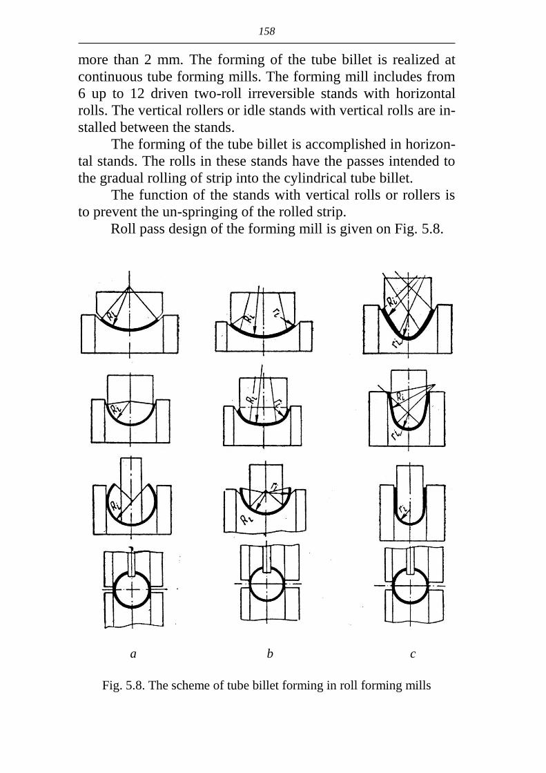
158
more than 2 mm. The forming of the tube billet is realized at
continuous tube forming mills. The forming mill includes from
6 up to 12 driven two-roll irreversible stands with horizontal
rolls. The vertical rollers or idle stands with vertical rolls are in-
stalled between the stands.
The forming of the tube billet is accomplished in horizon-
tal stands. The rolls in these stands have the passes intended to
the gradual rolling of strip into the cylindrical tube billet.
The function of the stands with vertical rolls or rollers is
to prevent the un-springing of the rolled strip.
Roll pass design of the forming mill is given on Fig. 5.8.
a b c
Fig. 5.8. The scheme of tube billet forming in roll forming mills

159
Single radius pass (Fig. 5.8, a) or double radius passes
(Fig. 5.8. b, c) are used for tube billet forming. Combination of
these types of passes is possible.
Technological scheme of tube production at continuous
plant is given on Fig. 5.9.
Fig. 5.9. Technological scheme of continuous plant
for longitudinal tubes resistance electric welding:
1 – decoiler; 2 – straightening machine; 3 – guillotine
shears; 4 – electric butt-welding machine; 5 – pulling roll-
ers; 6 – the loop accumulator of strip; 7 – circular shears for
strip edges cutting; 8 – continuous forming mill; 9 – electric
welding machine with rotary transformer; 10 – sizing mill;
11 – flying cutting device; 12 – heating pusher-type furnace;
13 – continuous mill of hot stretch-reducing of tubes; 14 –
hot sizing mill; 15 – flying cutting device; 16 – cooler
The technological process is accomplished in the follow-
ing succession.
The coil delivered to the mill is uncoiled in decoiler 1 and
is delivered for straightening to the 7-9 roller machine 2. The
strip after straightening is delivered to the guillotine shears 3
where the adjacent ends of two coils are cut for obtaining the
even butts and then they are welded in butt-welding machine 4
into the endless strip. The welding of the ends requires the
stoppage of the strip and for avoiding the continuous operation

160
mill stoppage the stock of the strip is produced in the form of
the loop 6. The strip is delivered to the circular shears 7 where
the side edges are cut for obtaining the strip of specified width
after leaving the looping device. Then the strip is delivered to
the continuous forming mill 8. The edges pressure welding is
carried out at the electric welded tube mill 9 installed just after
the continuous forming mill. Tube welding mill has two driven
stands with vertical rolls having round passes which diameter is
a little bit smaller than the diameter of the tube billet. The heat-
ing of the edges up to the welding temperature 1430-1440ºC is
carried out at tube welding mill. Different methods of edges
heating are used such as high frequency current, induction heat-
ing, heating by the direct current and other. The outside burr is
removed by cutters after welding and the tube is delivered to
the sizing mill 10 for sizing and further to the straightening ma-
chine for the preliminary straightening. The tubes are divided to
measured lengths or loops by the flying shears 11, they are
heated in heating pusher-type furnace 12 up to t=1000ºC, are
reduced at continuous reducing mill 13 for tube diameter reduc-
tion and are sized at continuous sizing mill 14. The tube coming
out of the sizing mill is cut to measured lengths by flying shears
15 and delivered to the cooler 16 for cooling.
At the finishing section the cooled tubes are straightened,
their ends are faced on special lathes, tubes are undergone to
hydro-testing for checking the solidity of the welded seams.
The tubes with spiral weld are widespread as their produc-
tion advantageously differs from longitudinal welded tubes
production because the simpler equipment is required for it and
the metal waste is decreased. Universality is the feature of the
method of spiral weld tubes production. That is the possibility
to produce different diameter tubes from the sheet of the same
width making only the mill change-over according to the
changed angle of the spiral and on the contrary it is possible to
produce the tubes of the same diameter from sheets and strips
of different width.
Forming, welding and cutting without stopping are the
main operations during spiral seam tubes welding. That is why

161
the spiral welding mill consists of three main mechanisms:
feeding; forming and welding; cutting.
The feeding mechanism of the mill uncoils the coil pre-
paring the strip edges (cleaning and flanging) and delivers the
strip with the required force and at the definite angle into the
forming and welding mechanism where the strip is rolled into
the spiral tube and then it is welded along the edges in continu-
ous seam. As the process of forming and welding is running
continuously the cutting to the measured lengths with cutting
torch is making without any stops. The whole cycle of the cut-
ting, that is switching on the cutting torch and ejecting device,
switching off the cutting torch and withdrawal of all mecha-
nisms of the cutting device to the starting position is accom-
plished automatically during one turn of tube, that is for one
spiral pitch.
The cut tubes are undergone to finishing operations (ends
sizing etc.) and hydro-testing methods.
The efficiency of this mill is 60-80 meters of tubes per
hour.
Tube welding mill of spiral welding may be traveling, in-
stalled on transporting machines. It permits to use the mill in
the field conditions, for example, for production and laying gas
pipeline tubes.
162
6. DRAWING, PRESSING AND
DIE FORGING PRODUCTION
6.1. Drawing
The technological process of drawing besides the proper
drawing includes operations of preparing metal surface for
drawing, intermediate heat treatment and finishing of the manu-
factured products.
The preparing of metal surface for drawing includes de-
scaling as well as applying the special layers on the metal for
lubricant fixing and producing insulation between the surfaces
of the metal and the die.
The removing of the scale is carried out by following
methods:
mechanical method by means of bending, twisting,
stretching, shot blasting and others;
chemical method by pickling in sulphuric, hydrochloric,
nitric, phosphoric acids; alkaline pickling in alkali dip,
gas pickling (pickling in the gas medium);
electro-chemical method by anode or cathode pickling.
The surface has to be cleaned after pickling in hot water
to remove the acid remains, salts and slime (mud) by means of
the strong cold water jet. Then the operation of applying the
bottom sub-lubricating layer comes. This layer consists of the
active molecules of isolating substance weakening the cohesion
between the metal and the die. The following bottom sub-
lubricating layer may be used:
sulling (corrosion) – applying the Fe(OH)2 layer by wa-
ter sprinkling of the pickled metal;
copper plating in copper sulfate (Fe+CuSO4→Cu+FeSO4)
solution;

163
phosphating – deposition of the insoluble salts of phos-
phoric acid on the metal surface;
oxalating (for high alloy steels) – deposition of oxalates.
The upper sub-lubricating layer forms the film between the
metal and the die and acts as the mechanical isolation. The upper
sub-lubricating layer applying is accomplished by liming in wa-
ter solution of Ca (OH)2 for neutralization of the acid remains
and washing off the fat lubricant as well as coating by borax and
liquid glass. The drying at 300-350ºC takes place in the chamber
after applying sub-lubricating layers for moisture removing and
corrosion stopping as well as for removing the hydrogen diffus-
ing into the metal what causes brittleness from pickling.
The drawing of the wire and small diameter tubes is car-
ried out in drum single- and multiblock machines (Fig. 6.1, a).
To introduce the billet into the die the leading part of the billet is
worked in such a way that dimensions of the first would be
smaller than dimensions of the die inlet. The billet is pressed
through the die and with help of the holder on the flexible cable
it is fixed to the drum. Then the drive of the drum is switched on
at a small speed and several coils of the wire are winded; after
that the holder is disconnected and later on the driving force is
provided only at the expense of friction forces between the coils
of the wire and the drum. The released leading end of the wire is
fed to the coiler (reeler) or to the next drum in multiblock ma-
chine having passed it previously through the next die.
The products of limited length and large cross section are
drawn at chain mills (Fig. 6.1, b). The chain mill represents hous-
ing between the side frames of which the Gall’s chain is traveling
on two star-wheels. The dies are installed in a special stop from
the side of non-driven star-wheel. The trolley with the hold and
swivel hook for coupling with the Gall’s chain is rolling along the
guides of the housing. The leading end of the billet is put through
the die and clenched with the holder installed on the trolley. By
means of the swivel hook the trolley is hooked for the traveling
chain link and the billet is being drawn. After the tail end’s exit
out from the die the hook is disconnected automatically with the
chain and the product is released from the holder. The trolley is
rolled back to the initial position.

164
а
Fig. 6.1. Scheme of drawing: a – the
drum drawing mill; b – the chain
drawing mill (1 – bed; 2 – Gall’s
chain; 3 – guides for the trolley; 4 –
non-driven star-wheel; 4a – driven
star-wheel; 5 – die; 6 – trolley; 7 –
holder for the billet; 8 – hook for the
trolley and chain coupling)
b
There are many special kinds of drawing besides conven-
tional one: with backward pull, with support, with heating, with
vibrations, through the rotating dies etc.
The methods of cold tube plug (mandrel) drawing and
sink drawing are shown on Fig. 6.2. The tubes of steel and al-
loys with diameter from 0.2 up to 765 mm with wall thickness
from 0.015 up to 40-50 mm and with length more than 50 m are
produced by drawing.
Drawing on stationary straight plug fixed on the rod is
the most widespread method (Fig. 6.2, a). It is used for drawing
tubes with diameter more than 8-10 mm when diameter and the
wall thickness of the tube should be reduced simultaneously.
The drawing of smaller diameter tubes by this method is limited
by the strength of the out-coming tube to the end of which the
pulling draw force Q is applied and a smaller diameter of the
rod, which the plug is fixed to.
Different methods of mandrel (plug) and sink cold draw-
ing of tubes are used. Mandrel drawing is used for reduction of
tube diameter and wall thickness.

165
Fig. 6.2. Methods of tube drawing:
a – on plug; b – on mandrel; c – on floating
mandrel; d – sink drawing; 1 – die; 2 – tube;
Q – drawing pull
Drawing on the moveable mandrel displacing together
with the tube is used for production of especially thin walled
tubes with diameter less than 8-10 mm with the high precision of
the geometrical parameters and high quality of inside and out-
side surface (Fig. 6.2, b). This method is the only one used for
production of tubes with diameter less than 3 mm and capillary
tubes of stainless steel with diameter les than 1.0 mm with wall
thickness from 0.2 up to 0.015 mm. The disadvantage of this
method, which limits its wide use is difficulty with the extraction
of the mandrel out of the tubes, especially of thin walled tubes.
The mandrel is tightly enveloped by tube and special operations
have to be used to facilitate the extraction of the plug.
Drawing on the self-centering mandrel is used mainly for
production of long length tubes up to 100 m and longer in case
of drum drawing when diameter and the wall thickness of the
tube should be reduced simultaneously. The stretching per pass
is 1.2-1.8. The form of the mandrel is chosen such as the forces
affecting the mandrel during the drawing process should pull it
a b
d c

166
into the deformation zone. That is why it is not necessary to fix
the mandrel on the rod (Fig. 6.2, c). The self-centering mandrel
is called sometimes floating mandrel.
Sink drawing is used in those cases when only diameter of
tube should be reduced (Fig. 6.2, d). Sink drawing is also used
as the final operation after rolling on cold rolling mills (CRM)
or after mandrel drawing. The stretching with this method
doesn’t exceed 1.5 and is limited by the strength of the out-
coming tube and stability of cross section in the deformation
zone (the tube has not to be crumpled).
The round and shaped tubes: square, rectangular, hexahe-
dral, oval and other shapes, are produced by drawing.
There are two types of multi-die (multi-block) machines:
without wire slipping on the pulling drum and with slipping.
The scheme of the multi-die machine without slipping with
wire accumulation on the drums is shown on Fig. 6.3, a.
a
b
c
Fig. 6.3. Scheme of multiple drawing mills:
a – multiple drawing mill without slipping (1 – die; 2 –
pulling drum; 3 – device for wire taking away from the
drum; 4 – guide rolls); b – looping type machine (1 –
die; 2 – pulling drum; 3 – tension roller); c – multiple
drawing with slipping (1 – die; 2 – fleet sheaves)

167
The speed of the drums is chosen in such a way that the previous drum had the stock of the wire. In case if the condition of synchronization of wire and drums speed is not observed, there is the possibility to compensate the fault of synchroniza-tion with the help of device 3 without mill stoppage due to the use of the wire stock.
The multiple drawing is perforemed at looping type mills without slipping with synchronization of the wire and drums speed (Fig. 6.3, b).
To prevent wire slipping on the drums the speed of latter is adjusted automatically during the process of drawing in such way as to avoid the wire accumulation. The adjustment is real-ized by means of the loop enveloping the tension roller. The turns of the drums are changed depending on position of the roller. If electric motors with soft mechanical properties will be used for pulling drums drive, the regulation of the drums speed may be done automatically due to the influence of the tension forces of the wire. The change of tension causes the change of the torque moment on the shaft of the motor and respective change of the rotating speed of the pulling drum.
The scheme of the multiple drawing with slipping is given on Fig. 6.3, c.
The wire is winded around the working drums one or sev-eral times depending on the diameter of the wire and the mill construction. The number of winds should provide for the nom-inal drawing force and exceed of the latter should cause the slipping of the wire winds on the drum. The slipping amounts 3-6% on the draught pulley (except receiving one) during the normal drawing process.
As the rotary velocity of pulleys (according to elongation) is increasing downstream the drawing, the relative downstream slipping has to be decreased from 6 to 3%.
The advantages of multiple drawing with slipping are as follows:
machines have simple construction and are convenient in loading;
pulleys and wire are placed into the liquid lubricant providing reliable lubrication and heat sink, high speeds of drawing.
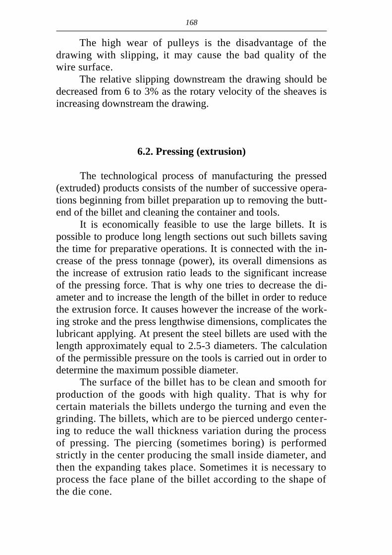
168
The high wear of pulleys is the disadvantage of the
drawing with slipping, it may cause the bad quality of the
wire surface.
The relative slipping downstream the drawing should be
decreased from 6 to 3% as the rotary velocity of the sheaves is
increasing downstream the drawing.
6.2. Pressing (extrusion)
The technological process of manufacturing the pressed
(extruded) products consists of the number of successive opera-
tions beginning from billet preparation up to removing the butt-
end of the billet and cleaning the container and tools.
It is economically feasible to use the large billets. It is
possible to produce long length sections out such billets saving
the time for preparative operations. It is connected with the in-
crease of the press tonnage (power), its overall dimensions as
the increase of extrusion ratio leads to the significant increase
of the pressing force. That is why one tries to decrease the di-
ameter and to increase the length of the billet in order to reduce
the extrusion force. It causes however the increase of the work-
ing stroke and the press lengthwise dimensions, complicates the
lubricant applying. At present the steel billets are used with the
length approximately equal to 2.5-3 diameters. The calculation
of the permissible pressure on the tools is carried out in order to
determine the maximum possible diameter.
The surface of the billet has to be clean and smooth for
production of the goods with high quality. That is why for
certain materials the billets undergo the turning and even the
grinding. The billets, which are to be pierced undergo center-
ing to reduce the wall thickness variation during the process
of pressing. The piercing (sometimes boring) is performed
strictly in the center producing the small inside diameter, and
then the expanding takes place. Sometimes it is necessary to
process the face plane of the billet according to the shape of
the die cone.

169
Four groups of metals are distinguished depending on the
temperature regime of pressing:
under 500ºC – aluminum, magnesium, zinc, lead alloys;
from 500 up to 900ºC – copper alloys;
from 900 up to 1300ºC – nickel, iron, titanium and other
hard-to-deform metals and alloys;
above 1300ºC – especially high-melting point metals.
At present the method of cold pressing is used more and
more widely for aluminum, titanium and other alloys.
The general requirement is to assure the uniform tempera-
ture of heating of all the billet volume. In this connection the
heating of the inner layer lower for 30-80ºC is expedient taking
into account the cooling of the surface.
The overheating (for 60-80ºC higher than at other meth-
ods of metal forming) is useful in many cases of alloyed steels
pressing. The increase of the grain during this heating doesn’t
affect the quality of the product at the high elongation ratio.
The lubrication of the tools causes the decrease of friction,
makes the process of the billet surface cooling slower and al-
lows to increase its length, deformation degree and the speed of
pressing. Besides that the lubricant preserves the tools from
overheating and increases the wear resistance of the latter. The
use of lubricant has also however its disadvantages like the ad-
ditional operations for removing the lubricant remains from the
metal surface.
Different lubricants are used for pressing the different met-
als. The type of lubricant depends upon the temperature of press-
ing. The most often used lubricant is the liquid one – engine oil
with fillers (graphite, talc, bentonite, kaolin and others). Alumi-
num, magnesium, and copper alloys are pressed however in the
most cases without any lubrication of the container in spite of
the advantages of using lubricants. Pressing (extrusion) without
lubricant leads to significant breaking of the surface layers of the
billet, to appearance of the high shear deformations spreading
deep into the billet. It causes the renewal of the metal layers,
which the surface of the pressed product is formed from.
The entry of the defects from the surface of the billet into
the surface of the product in this case is practically excluded

170
and the defect part of the metal is removed with the remainder
of the billet.
The process of hot pressing of ferrous metals has become
possible due to using the technological lubricants: at first
graphite-oil ones and then the glass ones.
The technology of the glass lubricant application con-
sists in the following. The glass washer mould of the pressed
glass grains is being put on the die heated up to 150-200ºC.
The liquid glass is used as the bond, which is gluing the
mass of the grains at 400-500ºC. The heated billet contacting
with the glass washer makes its surface to melt and takes the
melted layer into the hole of the die. Thus the zone of de-
formation is supplied with lubricant due to the glass washer.
Besides the billet is lubricated due to the application of the
layer of the glass grains onto the inclined table along which
the billet is rolling down after discharging from the furnace.
The glass grains are melted by the billet, which is rolling
down this layer and is being covered with the layer of lubri-
cant. The lubricating of the inner hole of the pierced billet is
provided by the portion of the glass grains, which is put in-
side by means of a special spoon.
It is necessary to produce the definite pressure in the main
cylinder and through the stem and press washer to force the bil-
let to enter the container for realization of the pressing process.
The scheme of construction of the bar and shapes extrusion
press with direct flow of the metal is given on Fig. 6.4. The die
fastened in the die holder 2 of sliding or rotary type is installed
in fixed front platen 1. During the process of extrusion the die
adjoins the container 3 and after finishing the extrusion it is
taken away from the container for removing the butt-end of the
billet by means of device 4. The stem 6 is fastened on the mov-
able ram 5. It realizes the extrusion of the metal out of the con-
tainer through the channel in the die by the force produced in
the main hydraulic cylinder. The press is equipped with the oil
accumulator 8 with the motor and control system.
Layout of the plant with horizontal hydraulic press for
production of steel tubes by method of extrusion is given on
Fig. 6.5.

171
Fig. 6.4. Scheme of the construction of the bar
and shape press with direct flow:
1 – the front platen; 2 – sliding or rotary die hold-
er; 3 – container; 4 – device for removing the
butt-end of the billet; 5 – ram; 6 – stem; 7 – back
cylinders; 8 – oil accumulator with the motor and
control system
Fig. 6.5. Technological scheme of the tube extrusion process
1 – receiving stand; 2 – conveyer; 3 – induction furnace
(50 Hz); 4 – the inclined table for glass lubricant; 5 – pierc-
ing press; 6 – pockets for the pierced shells; 7 – receiving
table for shells; 8 – induction pusher-type furnace (500 Hz);
9 – descaler; 10 – table for glass lubricant; 11 – hydraulic
press with 1600 t force; 12 – hot saw; 13 – cooler; 14 –
pockets; 15 – quenching bath

172
The prepared billets are supplied to the receiving stand 1
and then along the conveyer 2 to the induction furnace 3.
Passing its three inductors the billet is being heated up to
1180-1220ºC. After that the billet is supplied to the inclined
table 4 and rolls along it covering itself by the glass grains and
comes to the container of the piercing press 5. The process of
piercing includes pressing-out, piercing of the cup and punch-
ing the hole of the bottom. Then the shell is pushed out of the
container and delivered by the conveyer to the pockets 6. The
shells after cooling are put into the cartridges and are traveled
to the pickling. The shell is pickled to remove the remains of
the glass lubricant at the pickling area, clarified, controlled and
undergoes to the repair.
After that the shells are delivered to the receiving stand
7 of the main line and heated in the push-type induction fur-
nace 8, passed the hydraulic descaler 9, inclined table for
glass lubricant 10 and enter the press 11. The speed of press-
ing at presses with 16 and 31.5 MN is 400-500 mm/seс, the
elongation ratio is 6-20.
After removing the butt-end of the billet (by means of saw
12) the products are transported to the cooler 13 and then again
for pickling and straightening (tubes are straightened at the roll-
er straightening machines and the shaped products are straight-
ened at the stretching machine).
The process of extrusion permits to obtain the products
with different (including complicated one) shape of the cross
section (Fig. 6.6). In many cases it is not possible to produce
the long length shapes by other methods of metal forming. The
combination of the wide possibilities of obtaining the long
length products of various cross-section shapes with favorable
properties of material (especially in hot condition) makes the
extrusion process the first one for production of shapes, for in-
stance of aluminum alloys. Aluminum alloys extruded shapes
are the universal construction material with unique properties.
Thin-walled high strength shapes of aluminum alloys, for in-
stance alloyed by scandium, determine in many aspects the de-
velopment of aerospace engineering and transport machine
building. The reduction of the weight of the carriers provides

173
for significant reduction of energy consumption and harmful
emission to the environment. The use of the aluminum shapes
in construction has opened up the wide possibilities of the de-
velopment of modern urban architecture.
a b c
Рис. 6.6. Types of shapes:
a – solid; b – semi-hollow; c – hollow
6.3. Smith forging
The necessary blacksmith operations, their succession as
well as tools depend upon the configuration of the forged piece
and technological requirements, which are to be satisfied. In the
most of the cases in production of the forged pieces the alterna-
tion of upsetting and stretching takes place with predomination
of that or another operation depending on the shape of the
forged piece. The flat die is the most multi-purpose forging
tool. The cut dies are usually used for forging on plugs or for
stretching of low-plasticity metals.
The chamber furnaces are the most widespread in the
forge shops. The billets of the same type are heated in contin-
uous furnaces in case of forging. The adjusting of the heating
regime is accomplished according to the chemical composi-
tion of the metal and temperature interval of the plastic work-
ing for the latter.
The heating of the billets as well as cooling the forged
pieces are the important operations of the technological process

174
of the forged pieces production. The very quick cooling of the
forged pieces as well as the non-uniform one may bring to their
buckling and even to the cracks formation. The cooling of the
forged pieces produced of alloyed steels requires the special at-
tention. The small forged pieces are usually cooled on the air in
piles and the large ones are cooled in the holes with sand, in the
furnaces and pits.
The choice of the equipment for forging is to be made tak-
ing into account the thermo-mechanical regime of processing
the given metal or alloy connecting the speed of deformation
with heating temperature and the speed of re-crystallization.
High-alloyed steels (especially tool ones), heat-resistant and
some non-ferrous alloys have the low speeds of re-
crystallization as well as the low plasticity and don’t allow the
high speed of deformation. It is recommended to use the press-
es, but not the hammers to forge these metals.
The mass and the shape of the produced forged piece in-
fluence the choice of the equipment. The small and medium
mass forged pieces (up to 2-3 t) are usually produced on ham-
mers and the large up to 200-300 t are produced at presses.
The main characteristic of the hammers is the mass m of
the falling parts. The impact energy will be equal to Eimp=mv2/2
when the speed v of the falling parts of the hammer in the mo-
ment of impact is equal to 5-8 m/sес. The hammer impact ener-
gy is used for deformation not completely (part of it is wasted
for elastic deformation of the forged piece, for shaking of the
basement and the hammer etc.). The useful impact energy Аdef
used for plastic deformation of the forged piece is determined
by the following expression: Adef=Еimpimp (imp0,8 – coeffi-
cient of efficiency of the impact).
Hammers have mainly the mass of the falling parts equal
to 1-5 t and are used for production of medium mass forged
pieces from the small ingots, blooms and rolled ingots. The
small forged pieces are produced of rolled sections on the
hammers with the mass of the falling parts equal to 0.1-1.0 t.
The main types of the hammers for smith forging are
driving hammers – pneumatic and steam-air hammers. The

175
hammers differ by the type of the frame and may be single
frame and double frame, arch and bridge ones.
Pneumatic hammer has two cylinders – compressor and
working ones. The plunger in compressor cylinder is set into al-
ternate-reciprocal motion and compresses air by turns in the
upper and the bottom cylinder chamber up to 2-3 atmospheres
after switching on the motor. The compressed air is used in the
working chamber for lifting and lowering of the hammer block
connected with the working plunger. The control of the air dif-
fuser allows to run the forging by isolated impacts, to hold the
block hanging, to accomplish idling etc.
Steam-air hammers are put into action by the steam or
compressed air with the pressure 7-9 atm. The control of the
steam-air hammers is accomplished by means of the steam dif-
fuser regulating the entry of the steam into the working cylinder
and its exit out of the cylinder.
The coefficient of efficiency of the hammer impact de-
pends upon the correlation of the mass of the anvil block M and
the mass of the falling parts of the hammer m. The mass of the
anvil block is taken 15 times more than the mass of the falling
parts for the forging hammers.
The heavy forged pieces are produced of ingots at hydrau-
lic presses with the tonnage up to 150 MN.
The hydraulic presses are put into action by means of liq-
uid (water, oil). The pressure of the liquid more often is pro-
duced by means of plunger pumps during the press working.
Air-loaded accumulators and dead weight accumulators are
used for keeping the liquid pressure in the system and reducing
the required drive power of the drum.
Some types of the hydraulic presses have the system of
low pressure (up to 12 atm) produced by the pump with accu-
mulator and of high pressure (up to 200-500 atm).The high
pressure is produced by multiplier working due to the steam or
the air, hydraulic pump or mechanical transmission increasing
the pressure to 40-60 times.

176
6.4. Die forging
The general technological process of the forged pieces
production by the drop stamping includes the number of opera-
tions as follows: cutting of bars to the billets, heating, pressing,
cutting of the burr, straightening, heat treatment, descaling and
sizing. The rolled steel of different section shapes is used as the
billet for drop stamping. The different methods of cutting are
used: at crank-type press shears, cutting by saws, breaking, gas
and anode-mechanical cutting. The choice of the method of cut-
ting depends upon the size of billet section and technological
features of different steel grades.
The stamping hammers differ regarding construction from
the hammers for smith forging. All stamping hammers have
double frame. The motion of the hammer block is going on in
the regulated guides. The frames are installed on the anvil block
and connected with it by means of bolts with springs. It pro-
vides for the necessary precision of coincidence of the die fig-
ures. The correlation of the anvil block mass to the mass of fall-
ing parts is equal to 20 and sometimes it is up to 30 at the
stamping hammers.
The hammer die presents the massive block consisting of
two parts, which are often called the upper and the bottom dies.
The dies may be sub-press dies and the bed dies. The sub-
press dies are used in small-lot production in the forge shops.
The stamping is accomplished only in the bed die at the stamp-
ing shops. Hammer dies as a rule are opened ones and stamping
with the burr is accomplished in them.
The hammer dies usually have only one (finishing) groove
or at worst two grooves (roughing and finishing) grooves for
stamping the forging pieces of simple configuration.
The hammer dies for the complicated configuration forg-
ing pieces have two groups of grooves: the blanking (fuller,
edger, pinching, forming, bending etc.) and stamping (roughing
and finishing).
The dies for drop stamping work in the heavy-load condi-
tions as they are influenced by the sharply changed tempera-
tures and impacts. The wear of dies is accompanied by the

177
appearance of the fire cracks, flattening of the working edges.
The die steel must have high durability, hardness, impact
strength, high fire resistance, wear resistance, good hardening
capacity, high resistance for tempering. The dies are produced
of steels alloyed by chromium, nickel, tungsten, molybdenum,
vanadium, titanium etc. to ensure these properties.
The usage of the presses comparing with the hammers
gives the following important advantages such as a less shaking
of the earth, smaller basements, higher coefficient of operation
efficiency, higher productivity, higher precision of the forged
pieces, smaller stamping inclines etc.
The conditions of the metal deformation at the presses dif-
fer from those on the hammer. The first is due to the great differ-
ence in speeds of deforming tools (hammer speed is 5-8 m/sес
and the press speed is 0.5-0.6 m/sес) and the second is that due
to the strictly fixed value of the slider stroke. Using of special
measures, for example of non oxidating heating, is necessary
during the pressing process for descaling. Otherwise the scale
may be stamped into the forging piece.
Almost all types of the stamping work including multi
groove stamping (excluding blanking work in fuller and edg-
er grooves) may be accomplished at crank drop stamping
presses during production of the forged pieces with the mass
up to 100 kg. The presses with the tonnage from 6.3 up to
100 MN are used.
Kinematics of crank hot press is given on the Fig. 6.7.
The flywheel 3 located on the intermediate shaft 4 is rotat-
ing from the electric motor1 by means of V-belt drive 2. The
rotation from the shaft 4 through the gear transmission 5 is be-
ing sent to the crank shaft 6. The slide block 10 connected by
means of the connecting rod 7 with the crank shaft 6 receives
the alternate-reciprocal motion. The upper (moveable) part of
the die is fixed to the slide block 10 and the bottom (immova-
ble) is fixed to the press table 9. The pushers are placed in the
slide block and in the table used for removing the forging piece
from the die. Switch on and off of the crank gear mechanism is
accomplished by the friction sleeve 8 and the stoppage by the
band brake 11.

178
Fig. 6.7. Kinematics of crank hot press
The screw friction presses combine the impact action
and the static pressure that’s why they are considered to be
the intermediate types of machines between the hammers
and presses. These presses are constructed with the force
0.4-6.3 MN. The mass of the forged pieces processed at
these presses exceeds 20 kg.
Hydraulic forging presses don’t differ in principle from
the forging ones as to their construction.
Horizontal forging machines are the crank-lever-cam
mechanisms. The main point of the stamping at these machines
consists in clamping of the billet and up-end deformation of the
latter. There are two mechanisms in this machine: clamping and
deforming one.
The following main operations may be accomplished on
horizontal forging machine:
up-end swaging and upsetting of the middle part of the
billet;
deep piercing with expansion towards sides;

179
through piercing of the holes;
bending;
cutting of the forged piece from the rod billet.
The upsetting operations are mainly accomplished on hor-
izontal forging machines. The forging is usually accomplished
in several passes from one heating in consequence of what the
volume of the billet remains unchanged in all passes. The forg-
ing on horizontal forging machines has the following ad-
vantages:
the possibility of forging in the closed dies (without the
burr);
the possibility of zero-draft forging;
the high productivity (up to 900 pcs. per hour).
The high efficiency automatic machines are operating ac-
cording to the principle of the horizontal forging machines ac-
complishing the cold upsetting work. All fastening components
including bolts, nails, screws etc. are produced by cold upset-
ting. Calibrated metal mainly with round section and diameter
from 0.6 up to 38 mm is used as the billet for cold upsetting.
The metal wastes are absent or extremely small during manu-
facturing of products by cold upsetting.
6.5. Sheet metal stamping
The production of the parts by hot and cold sheet metal
stamping is accomplished at specialized shops having different
machines and lathes. These are parallel, inclined and disc
shears, crank (or eccentric) single-acting presses, double-action
presses, triple-acting presses, hydraulic presses as well as the
installations used for straightening and bending of sheets, bands
shaping etc.
There is only one slide block at the single-acting press,
which the punch is fixed at. These presses are used for blank-
ing, bending and some drawing operations, etc. The double-
action presses have two slide blocks (Fig. 6.8). The outer slide
block 4, which the blank holder 3 is fixed to, provides for nec-
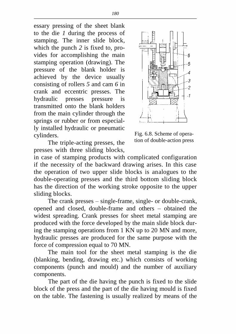
180
essary pressing of the sheet blank
to the die 1 during the process of
stamping. The inner slide block,
which the punch 2 is fixed to, pro-
vides for accomplishing the main
stamping operation (drawing). The
pressure of the blank holder is
achieved by the device usually
consisting of rollers 5 and cam 6 in
crank and eccentric presses. The
hydraulic presses pressure is
transmitted onto the blank holders
from the main cylinder through the
springs or rubber or from especial-
ly installed hydraulic or pneumatic
cylinders.
The triple-acting presses, the
presses with three sliding blocks,
in case of stamping products with complicated configuration
if the necessity of the backward drawing arises. In this case
the operation of two upper slide blocks is analogues to the
double-operating presses and the third bottom sliding block
has the direction of the working stroke opposite to the upper
sliding blocks.
The crank presses – single-frame, single- or double-crank,
opened and closed, double-frame and others – obtained the
widest spreading. Crank presses for sheet metal stamping are
produced with the force developed by the main slide block dur-
ing the stamping operations from 1 KN up to 20 MN and more,
hydraulic presses are produced for the same purpose with the
force of compression equal to 70 MN.
The main tool for the sheet metal stamping is the die
(blanking, bending, drawing etc.) which consists of working
components (punch and mould) and the number of auxiliary
components.
The part of the die having the punch is fixed to the slide
block of the press and the part of the die having mould is fixed
on the table. The fastening is usually realized by means of the
Fig. 6.8. Scheme of opera-
tion of double-action press
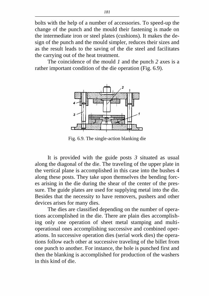
181
bolts with the help of a number of accessories. To speed-up the
change of the punch and the mould their fastening is made on
the intermediate iron or steel plates (cushions). It makes the de-
sign of the punch and the mould simpler, reduces their sizes and
as the result leads to the saving of the die steel and facilitates
the carrying out of the heat treatment.
The coincidence of the mould 1 and the punch 2 axes is a
rather important condition of the die operation (Fig. 6.9).
Fig. 6.9. The single-action blanking die
It is provided with the guide posts 3 situated as usual
along the diagonal of the die. The traveling of the upper plate in
the vertical plane is accomplished in this case into the bushes 4
along these posts. They take upon themselves the bending forc-
es arising in the die during the shear of the center of the pres-
sure. The guide plates are used for supplying metal into the die.
Besides that the necessity to have removers, pushers and other
devices arises for many dies.
The dies are classified depending on the number of opera-
tions accomplished in the die. There are plain dies accomplish-
ing only one operation of sheet metal stamping and multi-
operational ones accomplishing successive and combined oper-
ations. In successive operation dies (serial work dies) the opera-
tions follow each other at successive traveling of the billet from
one punch to another. For instance, the hole is punched first and
then the blanking is accomplished for production of the washers
in this kind of die.

182
In the mixed action dies several operations of sheet metal
stamping are accomplished per one stroke of the punch. For in-
stance, the blanking of the circle is made first for production of
the cup and then at the same stroke of the punch the drawing is
made. Five and more operations may be accomplished in multi-
operational dies.
The processes of sheet metal stamping are well mecha-
nized and automated while using the coil billets as well as the
piece blanks. The mechanical feeding of the strip to the die is
more often accomplished by the rollers which are turning at
regular intervals at the necessary moment at the definite angle
providing for traveling the strip for the value of the required
pitch. There is the great variety of devices for automatic sup-
ply of the piece blanks to the working tools. The feeding
mechanism has to ensure the definite orientation of the blank
in the space and ensure its next supply to the working tools.
The "mechanical arms" of different design are widely used for
sheet metal stamping using mechanical and automatic clamps
whose work is strictly synchronized with the work of the main
equipment.
The following equipment may be referred as to the auxil-
iary equipment of the stamping presses: cartridge devices feed-
ing the presses by the billets, mechanisms for removing the
parts from the dies, devices for applying the technological lub-
ricant before stamping, the mechanisms for removing the
wastes, the finished products counters.
It is advisable in many cases to arrange the production
equipment (necessary for accomplishing the technological op-
erations and products quality control) of the sheet stamping
shop as the continuous conveyer lines for ensuring the high
productivity at the all-around automation of the manufacturing.

183
QUESTIONS FOR EXAMINATION
1. What is the cause of the metal hardening during the cold
plastic deformation?
2. What processes accompany the hot plastic deformation?
3. What does the method of determination of the yield strength of
the processed metal at the hot plastic deformation consists of?
4. Explain the role of displacements in the metal plastic defor-
mation mechanisms.
5. Explain the influence of the stress scheme on the deformation
strain and the plasticity of the metal.
6. At which conditions does the initial bite of the strip by the
rolls take place?
7. Explain the notion of the coefficient of the force lever during
the rolling.
8. How the setting ratio is determined in the processes of the
smith forging?
9. Compare the advantages and disadvantages of the processes
of smith forging and die forging.
10. List the main operations of the sheet metal stamping.
11. Name and explain the purpose of the components of the
main line of the rolling mill.
12. What are the advantages of the multi-roll mill design.
13. Name the main components of the technological process of
the rolling manufacturing.
14. What are the advantages of the continuous mills?
15. What does the foundry-rolling complex represent?
16. Indicate the types of the section mills and the range of the
rolled products.
17. Indicate the types of the plate hot rolling mills and the range
of the rolled products.
18. Indicate the types of the plate cold rolling mills and the
range of the rolled products.

184
19. Give the characteristic of the small section continuous
mills.
20. Give the characteristic of the wire continuous mills.
21. Name the methods of seamless tube and pipe production.
22. Name the methods of welded tube and pipe production.
23. Give the characteristic of the cold rolling tube mills.
24. Name the methods of tube production by drawing.
25. Give the characteristic of the continuous mandrel mill.
26. Name the types of the continuous drawing mills.
27. Indicate the features of the deformation during internal ex-
trusion.
28. Name the advantages and disadvantages of the forging in
the closed dies.
29. Indicate the features of the press construction in sheet metal
production.
30. Name the technological operations in press-forging pro-
duction.

185
REFERENCE LIST
1. Грудев А.П., Машкин Л.Ф., Ханин М.И. Технология прокатного
производства: Учебник для вузов. – М.: Металлургия, 1994. –
640 с. (Grudev A.P., Mashkin L.F., Khanin M.I. The technology of the rolling manu-
facturing: The course for academies. – M.: Metallurgy, 1994. – 640 p.)
2. Технология трубного производства / В.Н. Данченко, А.П. Коли-
ков, Б.А. Романцев, С.В. Самусев. – М.: Интермет Инжиниринг,
2002. – 640 с. (The technology of the rolling manufacturing / V.N. Danchenko, A.P. Kolikov,
B.A. Romantsev, S.V. Samusev. – M.: Intermet Engineering, 2002. – 640 p.)
3. Теория и технология ковки: Учебное пособие для вузов / Л.Н. Со-
колов, Н.К. Голубятников, В.Н. Ефимов, И.П. Шелаев. Под. ред.
Н.М. Соколова. – К.: Вища школа, 1989. – 317 с. (The theory and the technology of forging: The text-book for academies /
L.N. Sokolov, N.K. Golubyatnikov, V.N. Yefimov, I.G. Shelaev. Edited by
N.M. Sokolov. – K.: The Higher School, 1989. – 317 p.)


Educational edition
Valentin Nikolayevich DANCHENKO
METAL FORMING
Text-book
N. A. Koriaka, Translation
Yu. Zh. Shpak, Computer Design
Подписано к печати 09.07.07. Формат 60х84 1/16. Бумага типогр.
Печать плоская. Уч.-изд. л. 10,76. Усл. печ. л. 10,62. Тираж 300 экз.
Заказ №____.
Национальная металлургическая академия Украины
49600, Днепропетровск-5, пр. Гагарина, 4
Редакционно-издательский отдел НМетАУ


UDC 621.771
The present book is recommended by the Ministry of education and science of
Ukraine as a text-book for students of higher educational institutions studying along
direction ''Metallurgy''
Danchenko V.N. Metal forming: text-book. – Dnepropetrovsk: NMetAU, 2007. –
183 p.
The fundamentals of metal forming theories, the theories
of processes of metal forming, forging and stamping as well as drawing and pressing (extrusion) have been given.
The characteristics of the shop equipment for metal form-ing and technology of the main metal forming methods have been given in separate sections.
The text-book is intended for students of higher educa-tional institutions, specialty "Metallurgy".
Fig. 80. Таble 3. Reference list: 3. The book is edited by the author. Приведены основы теории обработки металлов давле-
нием: прокатки, ковки и штамповки, а также волочения, прессования.
В отдельных разделах приведены характеристика обо-рудования цехов обработки металлов давлением и техно-логия основных видов обработки металлов давлением.
Предназначено для студентов по направлению "Ме-таллургия".
Ил. 80. Табл. 3. Библиогр.: 3 назв. Издается в авторской редакции.
Reviewers: G.V. Levchenko, Doctor in engineering Sciences (Iron and Steel Institute
of Ukraine Academy of Sciences)
S.M. Zhuchkov, Doctor in engineering Sciences (Iron and Steel Institute
of Ukraine Academy of Sciences)
G.P. Bloshtshinsky, Candidate in engineering Sciences (The State
Tube Institute)
© National metallurgy
academy of Ukraine, 2007
ISBN 996-525-716-1 © Danchenko V.N., 2007

MINISTRY of EDUCATION and SCIENCE of UKRAINE
NATIONAL METALLURGY ACADEMY of UKRAINE
V. N. DANCHENKO
METAL FORMING
The manuscript is approved at Academic
Council meeting of the National Metallurgical
Academy of Ukraine
Dnepropetrovsk NMetAU 2007

UDC 621.771
The manuscript is approved at Academic Council meeting of the National Metallur-
gical Academy of Ukraine
Danchenko V.N. Metal forming: text-book. – Dnepropetrovsk: NMetAU, 2007. –
183 p.
The fundamentals of metal forming theories, the theories
of processes of metal forming, forging and stamping as well as drawing and pressing (extrusion) have been given.
The characteristics of the shop equipment for metal form-ing and technology of the main metal forming methods have been given in separate sections.
The text-book is intended for students of higher educa-tional institutions, specialty "Metallurgy".
Fig. 80. Таble 3. Reference list: 3. The book is edited by the author. Приведены основы теории обработки металлов давле-
нием: прокатки, ковки и штамповки, а также волочения, прессования.
В отдельных разделах приведены характеристика обо-рудования цехов обработки металлов давлением и техно-логия основных видов обработки металлов давлением.
Предназначено для студентов по направлению "Ме-таллургия".
Ил. 80. Табл. 3. Библиогр.: 3 назв. Издается в авторской редакции.
Reviewers: G.V. Levchenko, Doctor in engineering Sciences (Iron and Steel Institute
of Ukraine Academy of Sciences)
S.M. Zhuchkov, Doctor in engineering Sciences (Iron and Steel Institute
of Ukraine Academy of Sciences)
G.P. Bloshtshinsky, Candidate in engineering Sciences (The State
Tube Institute)
© National metallurgy
academy of Ukraine, 2007
ISBN 996-525-716-1 © Danchenko V.N., 2007

Educational edition
Valentin Nikolayevich DANCHENKO
METAL FORMING
Text-book
R. O. Lasareva, Responsible for the issue
V. V. Yakimenko, Art Edition
V. V. Yakimenko, Technical Edition
V. M. Orischiy, Proof-reading
Yu. Zh. Shpak, Computer Design
N. A. Koriaka, Translation
Have been sent for printing 05.05.06. Signed for printing 12.05.06.
Format 84x108 1/32. Offset paper. Literary garniture.
Offset printing. Conditionally printed sheets – 9.66.
Conditionally paint-prints 9.66.
Publishers’ sheet-copies 9.14. Print run 300 pcs. Order No___.
Publishing House "Porogi''
60 Karl Marx Avenue, Dnepropetrovsk, 49000
Certificate of State Registration
Series DN No. 7 of 21.02.2000
Municipal enterprise "Nikopol city Printing House"
21, Electrometallurgists St., Nikopol, 53219
Certificate of State Registration
Series DN No. 21 of 25.07.2000
ISBN 996-525-716-1
Danchenko V.N.
D19. Metal forming. Text-book for students of higher educational institutions, specialty "Met-
allurgy". – Dnepropetrovsk; Porogi, 2006. – 183 p.
ISBN 996-525-716-1
The fundamentals of metal forming theories, the theories of processes of metal forming, forg-
ing and stamping as well as drawing and pressing (extrusion) have been given. The character-
istics of the shop equipment for metal forming and technology of the main metal forming
methods have been given in separate sections. The text-book is intended for students of high-
er educational institutions, specialty "Metallurgy".
BBK34.2
Ри
с. 5.1.
Схеми
прокат-
ки труб
у круг-
лому
калібрі
на ру-
хомій
оправці:
а – дов-
гій; б –
корот-
кій; в –
без
оправки