metallic materials — charpy pendulum impact test...
TRANSCRIPT
Reference numberISO 148-3:2008(E)
© ISO 2008
INTERNATIONAL STANDARD
ISO148-3
Second edition2008-12-15
Metallic materials — Charpy pendulum impact test — Part 3: Preparation and characterization of Charpy V-notch test pieces for indirect verification of pendulum impact machines
Matériaux métalliques — Essai de flexion par choc sur éprouvette Charpy —
Partie 3: Préparation et caractérisation des éprouvettes Charpy à entaille en V pour la vérification indirecte des machines d'essai mouton-pendule

ISO 148-3:2008(E)
PDF disclaimer This PDF file may contain embedded typefaces. In accordance with Adobe's licensing policy, this file may be printed or viewed but shall not be edited unless the typefaces which are embedded are licensed to and installed on the computer performing the editing. In downloading this file, parties accept therein the responsibility of not infringing Adobe's licensing policy. The ISO Central Secretariat accepts no liability in this area.
Adobe is a trademark of Adobe Systems Incorporated.
Details of the software products used to create this PDF file can be found in the General Info relative to the file; the PDF-creation parameters were optimized for printing. Every care has been taken to ensure that the file is suitable for use by ISO member bodies. In the unlikely event that a problem relating to it is found, please inform the Central Secretariat at the address given below.
COPYRIGHT PROTECTED DOCUMENT © ISO 2008 All rights reserved. Unless otherwise specified, no part of this publication may be reproduced or utilized in any form or by any means, electronic or mechanical, including photocopying and microfilm, without permission in writing from either ISO at the address below or ISO's member body in the country of the requester.
ISO copyright office Case postale 56 • CH-1211 Geneva 20 Tel. + 41 22 749 01 11 Fax + 41 22 749 09 47 E-mail [email protected] Web www.iso.org
Published in Switzerland
ii © ISO 2008 – All rights reserved
ISO 148-3:2008(E)
© ISO 2008 – All rights reserved iii
Contents Page
Foreword............................................................................................................................................................ iv Introduction ........................................................................................................................................................ v 1 Scope ..................................................................................................................................................... 1 2 Normative references ........................................................................................................................... 1 3 Terms and definitions........................................................................................................................... 1 3.1 Definitions pertaining to the machine ................................................................................................ 1 3.2 Definitions pertaining to energy.......................................................................................................... 2 3.3 Definitions related to groups of test pieces....................................................................................... 2 3.4 Definitions pertaining to test pieces................................................................................................... 2 4 Symbols and abbreviated terms ......................................................................................................... 3 5 Reference testing machine .................................................................................................................. 4 5.1 Characteristics ...................................................................................................................................... 4 5.2 Verification of reference testing machine .......................................................................................... 6 5.3 Use of reference testing machine ....................................................................................................... 6 6 Reference test pieces........................................................................................................................... 7 6.1 General................................................................................................................................................... 7 6.2 Material .................................................................................................................................................. 7 6.3 Dimensions............................................................................................................................................ 7 6.4 Marking .................................................................................................................................................. 8 6.5 Qualification of a batch of reference test pieces............................................................................... 8 6.6 Reference test piece sets..................................................................................................................... 8 7 Certificates for reference test pieces.................................................................................................. 9 8 Notes for using sets of reference test pieces.................................................................................... 9 Annex A (informative) Uncertainty of the certified KV value of Charpy reference materials ................... 12 Bibliography ..................................................................................................................................................... 19

ISO 148-3:2008(E)
iv © ISO 2008 – All rights reserved
Foreword
ISO (the International Organization for Standardization) is a worldwide federation of national standards bodies (ISO member bodies). The work of preparing International Standards is normally carried out through ISO technical committees. Each member body interested in a subject for which a technical committee has been established has the right to be represented on that committee. International organizations, governmental and non-governmental, in liaison with ISO, also take part in the work. ISO collaborates closely with the International Electrotechnical Commission (IEC) on all matters of electrotechnical standardization.
International Standards are drafted in accordance with the rules given in the ISO/IEC Directives, Part 2.
The main task of technical committees is to prepare International Standards. Draft International Standards adopted by the technical committees are circulated to the member bodies for voting. Publication as an International Standard requires approval by at least 75 % of the member bodies casting a vote.
Attention is drawn to the possibility that some of the elements of this document may be the subject of patent rights. ISO shall not be held responsible for identifying any or all such patent rights.
ISO 148-3 was prepared by Technical Committee ISO/TC 164, Mechanical testing of metals, Subcommittee SC 4, Toughness testing — Fracture (F), Pendulum (P), Tear (T).
This second edition cancels and replaces the first edition (ISO 148-3:1998) which has been technically revised.
ISO 148 consists of the following parts, under the general title Metallic materials — Charpy pendulum impact test:
⎯ Part 1: Test method
⎯ Part 2: Verification of testing machines
⎯ Part 3: Preparation and characterization of Charpy V-notch test pieces for indirect verification of pendulum impact machines
ISO 148-3:2008(E)
© ISO 2008 – All rights reserved v
Introduction
The suitability of a pendulum impact testing machine for acceptance testing of metallic materials has usually been based on a calibration of its scale and verification of compliance with specified dimensions, such as the shape and spacing of the anvils supporting the specimen. The scale calibration is commonly verified by measuring the mass of the pendulum and its elevation at various scale readings. This procedure for evaluation of machines had the distinct advantage of requiring only measurements of quantities that could be traced to national standards. The objective nature of these traceable measurements minimized the necessity for arbitration regarding the suitability of the machines for material acceptance tests.
However, sometimes two machines that had been evaluated by the direct-verification procedures described above, and which met all dimensional requirements, were found to give significantly different impact values when testing test pieces of the same material. This difference was commercially important when values obtained using one machine met the material specification, while the values obtained using the other machine did not. To avoid such disagreements, some purchasers of materials added the requirement that all pendulum impact testing machines used for acceptance testing of material sold to them must be indirectly verified by testing reference test pieces supplied by them. A machine was considered acceptable only if the values obtained using the machine agreed, within specified limits, with the value furnished with the reference test pieces.
Successful experience in the use of reference test pieces led to the requirement in ISO 148-2 that indirect verification must be performed using reference test pieces in addition to direct verification. National standards and codes also require indirect verification using reference test pieces; for example, EN 10045-2 and ASTM E 23 require the use of reference test pieces. The purpose of this part of ISO 148 is to specify the requirements, preparation and methods for qualifying test pieces used for the indirect verification of pendulum impact testing machines.

INTERNATIONAL STANDARD ISO 148-3:2008(E)
© ISO 2008 – All rights reserved 1
Metallic materials — Charpy pendulum impact test —
Part 3: Preparation and characterization of Charpy V-notch test pieces for indirect verification of pendulum impact machines
1 Scope
This part of ISO 148 covers the requirements, preparation and methods for qualifying test pieces used for the indirect verification of pendulum impact testing machines in accordance with ISO 148-2.
It specifies notched test pieces with nominal dimensions identical to those specified in ISO 148-1; however, the tolerances are more stringent.
NOTE 1 The chemical composition or heat treatment or both are varied according to the energy level desired.
NOTE 2 Reference test pieces are qualified on reference pendulum impact testing machines which are also described in this part of ISO 148.
2 Normative references
The following referenced documents are indispensable for the application of this document. For dated references, only the edition cited applies. For undated references, the latest edition of the referenced document (including any amendments) applies.
ISO 148-1, Metallic materials — Charpy pendulum impact test — Part 1: Test method
ISO 148-2, Metallic materials — Charpy pendulum impact test — Part 2: Verification of testing machines
3 Terms and definitions
For the purposes of this document, the following terms and definitions apply.
3.1 Definitions pertaining to the machine
3.1.1 industrial machine pendulum impact testing machine used for industrial, general or most research-laboratory testing of metallic materials
NOTE These machines are not used to establish reference values.
3.1.2 reference machine pendulum impact testing machine used to determine certified values for batches of reference test pieces

ISO 148-3:2008(E)
2 © ISO 2008 – All rights reserved
3.2 Definitions pertaining to energy
3.2.1 total absorbed energy KT total absorbed energy required to break a test piece with a pendulum impact testing machine, which is not corrected for any losses of energy
NOTE It is equal to the difference in the potential energy from the starting position of the pendulum to the end of the first half swing during which the test piece is broken.
3.2.2 absorbed energy K energy required to break a test piece with a pendulum impact testing machine, after correction for friction
NOTE The letter V or U is used to indicate the notch geometry, that is KV or KU. The number 2 or 8 is used as a subscript to indicate striker radius, for example KV2.
3.2.3 reference absorbed energy KR certified value of absorbed energy assigned to the test pieces used to verify the performance of pendulum impact testing machines
3.3 Definitions related to groups of test pieces
3.3.1 batch definite quantity of reference test pieces manufactured under identical conditions of production, with a common certified absorbed energy
3.3.2 set group of test pieces chosen at random from a batch
3.3.2.1 characterization set set of test pieces taken from a batch in accordance with Clause 6 and used to determine the reference energy of the batch
3.3.2.2 reference set set of test pieces chosen in accordance with Clauses 6 and 8 and used to verify a pendulum impact testing machine
3.4 Definitions pertaining to test pieces
3.4.1 height distance between the notched face and the opposite face
3.4.2 width dimension perpendicular to the height that is parallel to the notch
3.4.3 length largest dimension perpendicular to the notch
ISO 148-3:2008(E)
© ISO 2008 – All rights reserved 3
3.4.4 reference test piece impact test piece used to verify the suitability of pendulum impact testing machines by comparing the indicated absorbed energy measured by that machine to the reference absorbed energy associated with the test pieces
3.4.5 certified reference test piece impact test piece accompanied by a certificate the certified absorbed energy value, KR, accompanied by an uncertainty at a stated level of confidence
NOTE The certified reference value is the value determined by a certified national or international body.
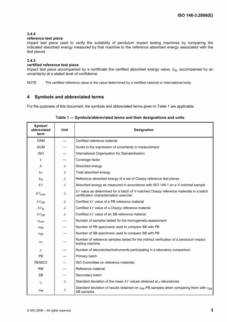
4 Symbols and abbreviated terms
For the purposes of this document, the symbols and abbreviated terms given in Table 1 are applicable.
Table 1 — Symbols/abbreviated terms and their designations and units
Symbol/ abbreviated
term Unit Designation
CRM — Certified reference material
GUM — Guide to the expression of uncertainty in measurement
ISO — International Organization for Standardization
k — Coverage factor
K J Absorbed energy
KT J Total absorbed energy
KR J Reference absorbed energy of a set of Charpy reference test pieces
KV J Absorbed energy as measured in accordance with ISO 148-1 on a V-notched sample
charKV J KV value as determined for a batch of V-notched Charpy reference materials in a batch certification characterization exercise
KVPB J Certified KV value of a PB reference material
RKV J Certified KV value of a Charpy reference material
KVSB J Certified KV value of an SB reference material
nhom — Number of samples tested for the homogeneity assessment
nPB — Number of PB specimens used to compare SB with PB
nSB — Number of SB specimens used to compare SB with PB
nV — Number of reference samples tested for the indirect verification of a pendulum impact testing machine
p — Number of laboratories/instruments participating in a laboratory comparison
PB — Primary batch
REMCO — ISO Committee on reference materials
RM — Reference material
SB — Secondary batch
sp J Standard deviation of the mean KV values obtained at p laboratories
sPB J Standard deviation of results obtained on nPB PB samples when comparing them with nSBSB samples
ISO 148-3:2008(E)
4 © ISO 2008 – All rights reserved
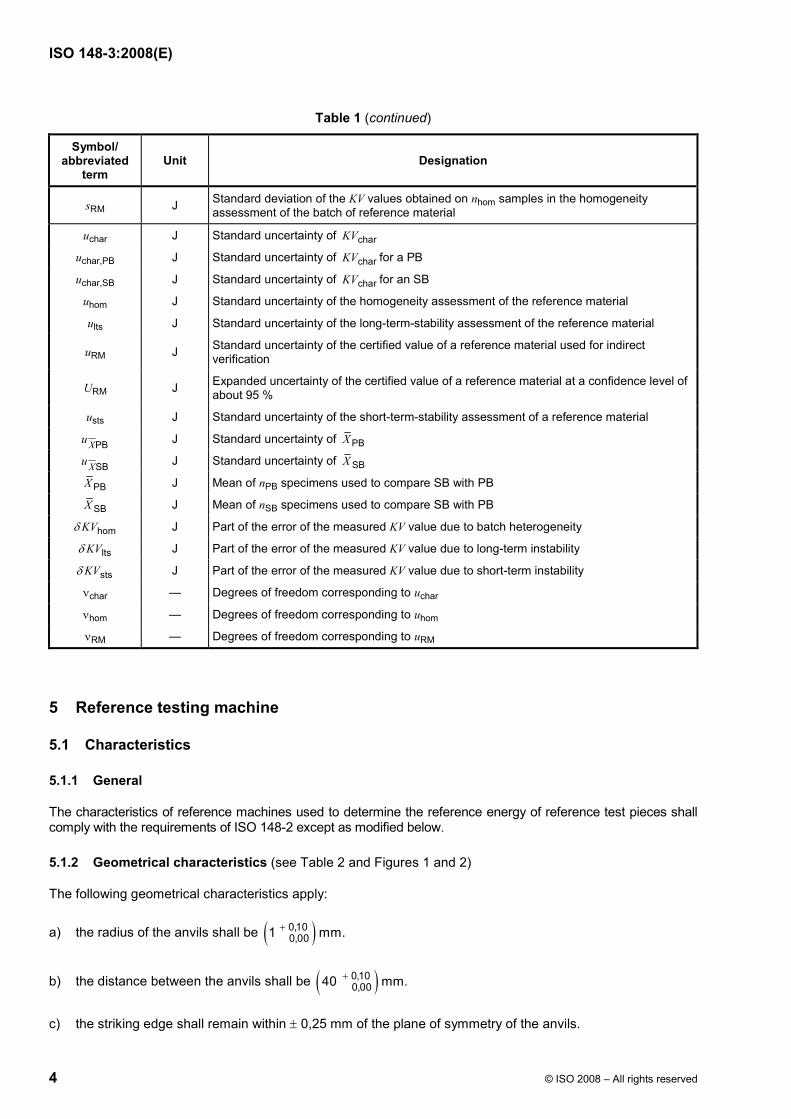
Table 1 (continued)
Symbol/ abbreviated
term Unit Designation
sRM J Standard deviation of the KV values obtained on nhom samples in the homogeneity assessment of the batch of reference material
uchar J Standard uncertainty of charKV
uchar,PB J Standard uncertainty of charKV for a PB
uchar,SB J Standard uncertainty of charKV for an SB
uhom J Standard uncertainty of the homogeneity assessment of the reference material
ults J Standard uncertainty of the long-term-stability assessment of the reference material
uRM J Standard uncertainty of the certified value of a reference material used for indirect verification
URM J Expanded uncertainty of the certified value of a reference material at a confidence level of about 95 %
usts J Standard uncertainty of the short-term-stability assessment of a reference material
PBXu J Standard uncertainty of PBX
SBXu J Standard uncertainty of SBX
PBX J Mean of nPB specimens used to compare SB with PB
SBX J Mean of nSB specimens used to compare SB with PB
homKVδ J Part of the error of the measured KV value due to batch heterogeneity
ltsKVδ J Part of the error of the measured KV value due to long-term instability
stsKVδ J Part of the error of the measured KV value due to short-term instability
νchar — Degrees of freedom corresponding to uchar
νhom — Degrees of freedom corresponding to uhom
νRM — Degrees of freedom corresponding to uRM
5 Reference testing machine
5.1 Characteristics
5.1.1 General
The characteristics of reference machines used to determine the reference energy of reference test pieces shall comply with the requirements of ISO 148-2 except as modified below.
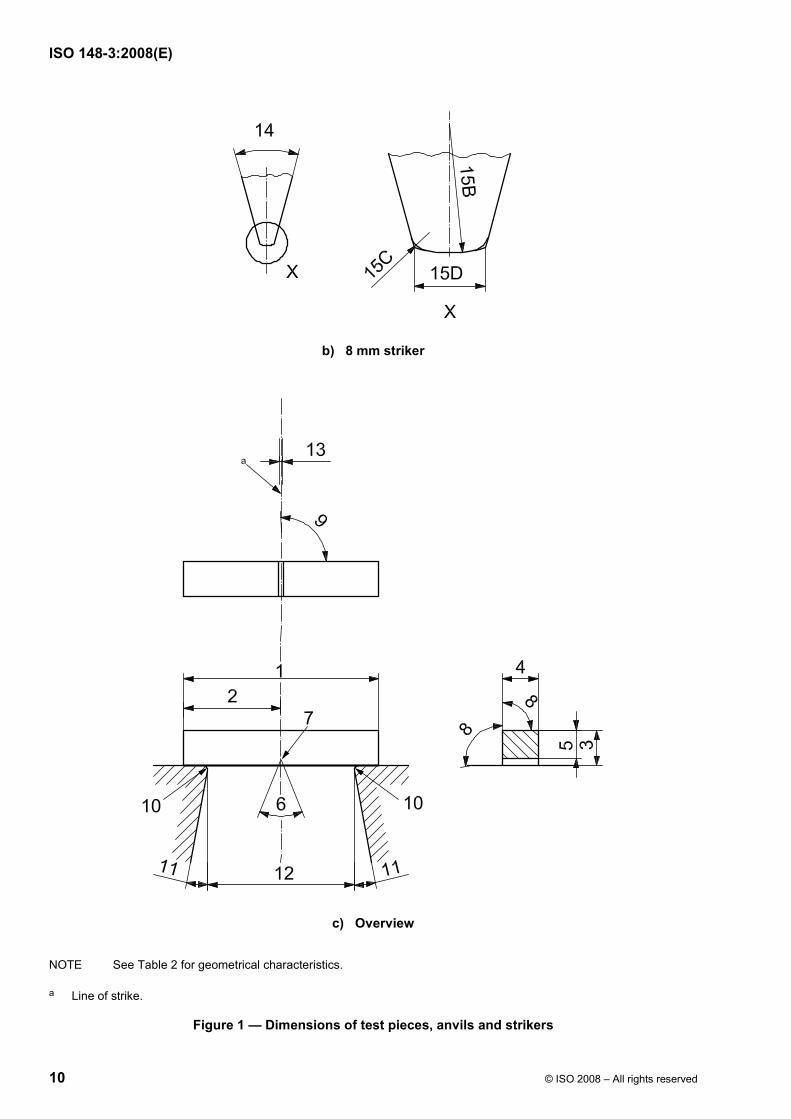
5.1.2 Geometrical characteristics (see Table 2 and Figures 1 and 2)
The following geometrical characteristics apply:
a) the radius of the anvils shall be ( )0,100,001 mm.+
b) the distance between the anvils shall be ( )0,100,0040 mm.+
c) the striking edge shall remain within ± 0,25 mm of the plane of symmetry of the anvils.

ISO 148-3:2008(E)
© ISO 2008 – All rights reserved 5
Table 2 — Geometrical characteristics
Reference number a Designation Value Tolerance Units
1 Length of test piece 55,00 +0,00 −0,30 * mm
2 Half-length of test piece 27,5 ± 0,2 * mm
3 Height of test piece 10,00 ± 0,06 mm
4 Width of test piece 10,00 ± 0,07 * mm
5 Ligament length 8,00 ± 0,06 mm
6 Angle of notch 45,0 ± 1,0 * degree
7 Radius of curvature at base of notch 0,250 ± 0,025 mm
8 Angle between adjacent faces 90,00 ± 0,15 * degree
9 Angle between plane of symmetry of notch and longitudinal axis 90 ± 2 degree
10 Radius of anvils 1,00 +0,10 −0,00 * mm
11 Angle of taper of anvils 11 ± 1,0 degree
12 Distance between anvils 40,00 +0,10 −0,00 * mm
13 Distance of striking edge from plane of symmetry of anvils — ± 0,25 * mm
14 Angle of striker 30 ± 1 degree
15A Radius of striking edge of 2 mm striker 2,00 +0,20 −0,00 * mm
15B Radius of striking edge of 8 mm striker 8,00 ± 0,05 mm
15C Radius of shoulder of 8 mm striker 0,25 ± 0,05 mm
15D Width of striking edge of 8 mm striker 4,00 ± 0,05 mm
NOTE 1 Tolerances followed by an asterisk (*) are tighter than those in ISO 148-1 or ISO 148-2.
NOTE 2 Subsize specimens may be used, but the tolerance should change proportionally.
NOTE 3 See Figures 1 and 2.
a See Figure 1.
5.1.3 Capacity
The capacity of a reference machine (nominal initial potential energy) shall be 300 J or greater.
5.1.4 Hardness
The portions of the striker and the anvils (see Figure 1) that contact the specimen and apply or react to the impacting force shall have a minimum hardness of 56 HRC.
5.1.5 Vibration
Ensure that the reference machine is not subjected to external vibrations induced by other equipment in close proximity, such as forging hammers, presses, moving vehicles.
ISO 148-3:2008(E)
6 © ISO 2008 – All rights reserved
NOTE Such vibrations can be detected by placing a small container of water at any convenient location on the machine framework; the absence of ripples on the water surface indicates that this requirement has been met. Excessive vibration in a machine firmly fastened to the floor indicates the need for a separate foundation and/or the use of vibration isolators.
5.1.6 Energy-indicating mechanism
The resolution shall be at least 1/400th of the nominal energy.
5.2 Verification of reference testing machine
Direct verification shall be carried out in accordance with ISO 148-2 and with the additional requirements of 5.1.
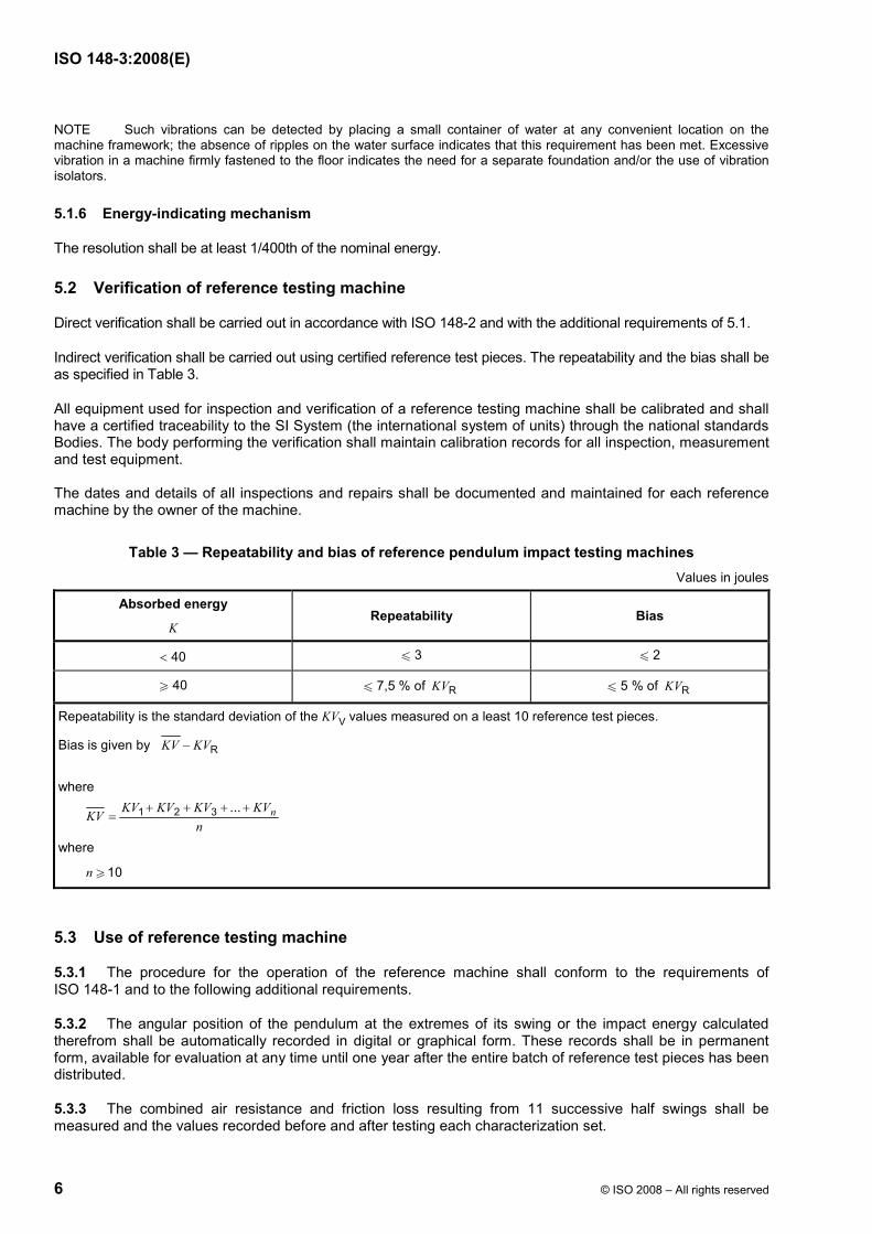
Indirect verification shall be carried out using certified reference test pieces. The repeatability and the bias shall be as specified in Table 3.
All equipment used for inspection and verification of a reference testing machine shall be calibrated and shall have a certified traceability to the SI System (the international system of units) through the national standards Bodies. The body performing the verification shall maintain calibration records for all inspection, measurement and test equipment.
The dates and details of all inspections and repairs shall be documented and maintained for each reference machine by the owner of the machine.
Table 3 — Repeatability and bias of reference pendulum impact testing machines Values in joules
Absorbed energy
K Repeatability Bias
< 40 u 3 u 2
W 40 u 7,5 % of RKV u 5 % of RKV
Repeatability is the standard deviation of the KVV values measured on a least 10 reference test pieces.
Bias is given by R KV KV−
where
1 2 3 ... nKV KV KV KVKV
n+ + + +
=
where
10n W
5.3 Use of reference testing machine
5.3.1 The procedure for the operation of the reference machine shall conform to the requirements of ISO 148-1 and to the following additional requirements.
5.3.2 The angular position of the pendulum at the extremes of its swing or the impact energy calculated therefrom shall be automatically recorded in digital or graphical form. These records shall be in permanent form, available for evaluation at any time until one year after the entire batch of reference test pieces has been distributed.
5.3.3 The combined air resistance and friction loss resulting from 11 successive half swings shall be measured and the values recorded before and after testing each characterization set.

ISO 148-3:2008(E)
© ISO 2008 – All rights reserved 7
5.3.4 The anvils and striker shall be inspected and measured for compliance annually. If any parts are found to be damaged, they shall be replaced and the machine shall be re-qualified (see 5.1 and 5.2).
During the annual inspection of the reference machine, the flatness of the anvil surfaces (which absorb the force transmitted through the test piece) and the adjacent radii shall be examined for wear or damage. The results of this examination shall be retained until the anvils are replaced or re-machined.
NOTE This examination can be done, for example, by making a replica of the surfaces in silicone rubber or another low-shrinkage material, or by holographic methods.
The radius (radii) of the striking edge of the striker and the radii of the anvil surfaces which are contacted by the test piece shall be measured and documented in the same manner.
If it becomes necessary to repair the recording system, it shall be recalibrated before additional tests are made (see 5.2).
6 Reference test pieces
6.1 General
Guidelines for the preparation, certification, and use of (certified) reference materials have been drawn up by ISO REMCO, the ISO Committee on reference materials (see References [1] to [5]). The procedures described below provide more details, specific to the case of Charpy reference test pieces.
6.2 Material
All the test pieces from a batch shall come from a single ingot or melt.
All test pieces shall be made of steel. The composition of the test pieces is not specified. Batches with different energy levels may have different compositions.
All test pieces from a batch shall receive the same heat treatment.
For each batch, the level for the reference absorbed energy is characterized by using one the following ranges:
⎯ Low: < 30 J
⎯ Medium: W 30 J to 110 J
⎯ High: W 110 J to 200 J
⎯ Ultra-high: W 200 J
6.3 Dimensions
The reference test pieces shall meet the dimensional requirements given in Table 2.
NOTE These dimensions are identical with those in ISO 148-1 except that some of the tolerances are tighter.
The radius at the base of the notch shall be tangential to the notch angle.
The surface finish, Ra, shall not exceed 1,6 µm on the notched surface and 3,2 µm on the other surfaces.
ISO 148-3:2008(E)
8 © ISO 2008 – All rights reserved
6.4 Marking
All test pieces shall be permanently marked so that each test piece can be distinguished from all the others.
The test piece may be marked on any face not in contact with supports, anvils or striker and at a position that avoids the effects of plastic deformation and surface discontinuities on the absorbed energy measured in the test.
6.5 Qualification of a batch of reference test pieces
6.5.1 Any group of test pieces meeting the requirements of 6.2, 6.3 and 6.4 may be used as the batch from which reference test pieces are randomly selected.
6.5.2 To determine the reference energy of a batch, draw one or more sets of at least 25 test pieces at random from the batch and test them on one or more reference machine(s). Take the reference absorbed energy of the batch as the grand average of the values obtained for the 25 or more test pieces, or as the average of the mean values obtained on the different reference machines.
NOTE The certified values can be determined using other methods, providing the method used conforms to ISO Guides 34 and 35.
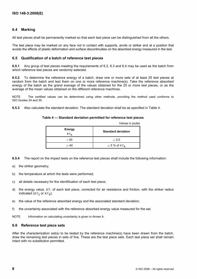
6.5.3 Also calculate the standard deviation. The standard deviation shall be as specified in Table 4.
Table 4 — Standard deviation permitted for reference test pieces Values in joules
Energy KVR
Standard deviation
< 40 u 2,0
W 40 u 5 % of KVR
6.5.4 The report on the impact tests on the reference test pieces shall include the following information:
a) the striker geometry;
b) the temperature at which the tests were performed;
c) all details necessary for the identification of each test piece;
d) the energy value, KV, of each test piece, corrected for air resistance and friction, with the striker radius indicated (KV2 or KV8);
e) the value of the reference absorbed energy and the associated standard deviation;
f) the uncertainty associated with the reference absorbed energy value measured for the set.
NOTE Information on calculating uncertainty is given in Annex A.
6.6 Reference test piece sets
After the characterization set(s) to be tested by the reference machine(s) have been drawn from the batch, draw the remaining test pieces in sets of five. These are the test piece sets. Each test piece set shall remain intact with no substitution permitted.

ISO 148-3:2008(E)
© ISO 2008 – All rights reserved 9
7 Certificates for reference test pieces
Each set of reference test pieces shall be accompanied by a certificate which gives the following information:
a) a reference to this part of ISO 148, i.e. ISO 148-3:2008;
b) the name, trademark or reference number of the producer;
c) the reference absorbed energy value of the set and its uncertainty at the stated level of confidence;
d) the striker geometry;
e) the temperature at which the reference absorbed energy was determined;
f) all details necessary for the identification of the reference machine(s) used to determine the reference energy (and necessary information concerning the use of the reference test pieces);
g) name and general description of the material;
h) producer's code for the batch;
i) intended use (making reference to ISO 148-2);
j) description of the (metrologically valid) procedure used to determine the certified value;
k) statement on the metrological traceability of the certified value;
l) storage conditions and shelf-life (period of validity).
8 Notes for using sets of reference test pieces
8.1 Indirect verification of an industrial machine shall be performed in accordance with ISO 148-2 using the reference test pieces, the striker and the temperature specified by the producer of the test pieces.
8.2 All the reference test pieces in each set shall be used for a single, indirect verification of the pendulum impact testing machine, testing the test pieces in random order and including all the results in the average. Substitution or replacement of individual test pieces by test pieces from another reference set is not permitted.
a) 2 mm striker
Figure 1 (continued)
ISO 148-3:2008(E)
10 © ISO 2008 – All rights reserved
b) 8 mm striker
c) Overview
NOTE See Table 2 for geometrical characteristics.
a Line of strike.
Figure 1 — Dimensions of test pieces, anvils and strikers

ISO 148-3:2008(E)
© ISO 2008 – All rights reserved 11
Key 1 anvil 2 height of test piece 3 width of test piece 4 length of test piece 5 reference test piece 6 centre of strike 7 recess 8 test-piece supports
Figure 2 — Configuration of test-piece supports and anvils in a reference pendulum impact testing machine
ISO 148-3:2008(E)
12 © ISO 2008 – All rights reserved
Annex A (informative)
Uncertainty of the certified KV value of Charpy reference materials
A.1 Background
When performing an indirect verification of a pendulum impact testing machine, one compares the reference KV value of the reference test pieces with values measured on the pendulum impact testing machine under verification. To determine the measurement uncertainty of this indirect verification exercise (see for example the procedures proposed in Reference [1]), and, later, the measurement uncertainty of Charpy measurements on the verified pendulum impact testing machine, one needs the uncertainty of the reference value. Therefore, this uncertainty must be assessed and provided by the reference material (RM) producer.
The ISO Committee on reference materials (REMCO) has drawn up a series of documents on reference materials production and use, which are released as ISO Guides (see References [1] to [5]). Approaches to tackling the uncertainty aspect of RM production are described in generic terms in ISO Guide 34 [4] and in more technical-statistical detail in ISO Guide 35 [5]. This informative annex provides an ISO-Guides-compliant practical framework for the calculation of the uncertainty of the certified absorbed energy value of a Charpy RM. The text is based on current approaches followed by national metrology institutes (NMIs) active in the Charpy field. The approaches presented here can be used as a guideline by potential new Charpy RM producers, as well as by the users of Charpy RMs who require more insight into the uncertainty stated by the RM producer on the RM certificate.
A.2 The GUM-compliant uncertainty budget
ISO Guide 35 [5] provides a basic, GUM [7]-compliant model for certification of batches of certified reference materials (CRMs). In Charpy terms, the model can be expressed as follows:
R char hom lts stsKV KV KV KV KVδ δ δ= + + + (A.1)
where
KVchar is the KV value obtained from the characterization of the batch (comparing results from different instruments);
δKVhom is an error term due to variation between samples (comparing results in repeatability conditions on a single pendulum);
δKVlts, δKVsts are error terms due to the long-term and short-term instability of the RM (comparing results of samples exposed to different ageing periods).
Homogeneity and stability studies are most often designed in such a way that the values of the corresponding error terms are zero. However, the uncertainties of the error terms are not (always) zero. Assuming independence of the variables, the uncertainty of the certified value of the Charpy RM, therefore, can be expressed as:
2 2 2 2RM char hom lts stsu u u u u= + + + (A.2)
The better the within-instrument repeatability and the between-instrument reproducibility, the smaller uchar will be. The better the between-sample homogeneity, the smaller uhom will be. Sometimes, the material homogeneity is very good, and uhom is dominated by within-instrument repeatability. This is not the case for typical Charpy RMs. The better the stability of the RM microstructure, under the appropriate transport and storage conditions, the smaller usts and ults will be.
ISO 148-3:2008(E)
© ISO 2008 – All rights reserved 13
A.3 KVR, the certified KV of a batch of Charpy RMs
Charpy RMs are produced batch-wise. The KV values of samples from a single batch vary from sample to sample. Yet, the whole batch will be assigned a single certified KV value. Obviously, this could be best estimated by testing all samples. However, since the impact test is destructive, there would be no samples left for distribution as reference materials. Instead, a representative selection of samples is taken from the batch and tested. An average value will become the certified value, KVR. This can be the average of all samples tested, or the average of the mean values of a number of subgroups of the samples tested.
A.4 uchar, the uncertainty of the average KV of a batch of Charpy RMs
A.4.1 Differences between pendulum impact testing machines
Even if one would break all samples of a batch to determine the average KV of the batch, still the question remains whether the average value obtained under the particular test conditions is affected by inaccuracies in the tests performed. To reduce this uncertainty, RM producers generally try to measure the property to be certified in different independent ways. For properties such as the chemical composition of an RM, one can often use different methods. However, in the case of pendulum impact tests, the only way to measure the “method-defined” KV value is to do Charpy pendulum impact tests in accordance with the applicable standard procedure (ISO 148-1), to which the certified values will be metrologically traceable.
To reduce the effect of machine-specific bias from the standard procedure on the certified reference values, one often performs pendulum impact tests on several pendulum impact testing machines. The larger the number of pendulum impact testing machines used to assess the average of a single batch of samples, the more likely it is that the average of the values obtained is true and unbiased. Of course, this is only true at the condition that individual participating pendulums are good quality instruments. This is the approach of both inter- and intralaboratory comparisons, currently followed in Charpy reference material certification, and recommended in ISO Guide 35 [5].
A.4.2 Intercomparison among p pendulum impact testing machines (p W 6)
When a sufficient number of machines participate in a comparison, the standard uncertainty of the average value is calculated as:
charps
up
= (A.3)
where
uchar is the uncertainty from the characterization of the batch;
p is the number of laboratories or instruments participating in the intercomparison;
sp is the standard deviation of the laboratory mean values.
This approach assumes that the individual laboratory mean values are normally distributed, and that the instruments or laboratories participating are a representative sample from the population of Charpy pendulum impact testing machines that meet the dimensions and performance criteria specified in ISO 148-2. The number of degrees of freedom, νchar, associated with this way of calculating uchar is p − 1. ISO Guide 35 [5] recommends a minimum number of six laboratories or instruments for this approach (ISO Guide 35:2006, 9.4.2.3.1).
A.4.3 Intercomparison among p pendulum impact testing machines (p < 6)
When the number of instruments participating to the comparison is limited, the value sp is not a reliable estimate of the standard deviation of the mean values between instruments. To assess uchar, other methods have to be used. These methods combine the systematic differences observed between the instruments
ISO 148-3:2008(E)
14 © ISO 2008 – All rights reserved
participating in the intercomparison (between-instrument uncertainty) and the measurement uncertainty assessed for the individual instruments (within-instrument uncertainty). An example is the so-called “BOB” or Type-B-on-bias-approach (see Reference [9]).
To have better control over the quality of the impact pendulums participating in the certification exercise, some CRM producers prefer to limit the number of impact pendulums to those in their own laboratory (intralaboratory). This approach offers the benefit of better defining the range for acceptable machine performance. However, it can be argued that it affects the independence of the averaged values. This is why the interlaboratory comparison is generally preferred in ISO Guide 35 [5].
A.5 Uncertainty due to material instability
The stability of the certified value of a CRM is typically threatened by two possible effects: degradation of the material during transport from producer to user (short-term stability), and degradation of the material during storage between the moment of production and the distribution to the CRM user (long-term stability). In the case of the steels currently used for the production of Charpy CRMs, neither short- nor long-term stability has presented problems (see References [10] and [11]). However, this should remain a subject of investigation, especially when selecting new types of steel for the production of Charpy CRMs. Until then, the values for ults and usts are considered negligibly small.
A.6 Uncertainty due to sample-to-sample variation — Homogeneity of the batch
Due to the heterogeneity of the steel microstructure, and the nature of the impact fracture process, samples from the same batch often have measurably different KV values. This implies that the average value of the set of verification test pieces tested by the CRM user is not exactly the same as the average of the RM batch from which the set was drawn.
For a single sample, the standard uncertainty, uhom, associated with this homogeneity issue equals the standard deviation of the batch, sRM. To assess this standard deviation, tests are performed on a representative number of samples nhom, selected from the batch. The tests are performed in repeatability conditions, excluding or at least minimizing the contributions to the standard deviation coming from machine, operator or other factors.
NOTE The value of sRM can also be deduced from the results of the interlaboratory comparison (see A.4). In this case, the within-laboratory and the between-laboratory variance of the results are separated using ANOVA (analysis of variance). The within-laboratory variance is related to the sRM.
Experience has shown that it is difficult to obtain large batches of Charpy reference test pieces with a standard deviation smaller than 3 %. At least, this is the case for the hardenable kind of steels needed for the production of samples at different energy levels with a minimum hardness, so as to truly put the pendulum to a test during verification. To reduce this relatively large contribution to the overall uncertainty of the certified value, it is common practice that the CRM user tests a set of samples of the batch, rather than a single sample, to verify a pendulum. (Actually, ISO 148-2 prescribes the use of five test pieces.) The chances that the average of a set of test pieces equals the average of the whole batch increases with nV, the number of test pieces used in the indirect verification, reducing the corresponding uncertainty contribution according to Equation (A.4):
RMhom
V
sun
= (A.4)
The number of degrees of freedom of this uncertainty contribution, νhom, equals (nhom − 1).

ISO 148-3:2008(E)
© ISO 2008 – All rights reserved 15
A.7 Combined and expanded uncertainty of the certified value, and how to report them
If the uncertainty contributions from material instability can be neglected, the combined standard uncertainty, uRM, is calculated from the remaining standard uncertainty contributions, uchar and uhom, as follows:
2 2RM char homu u u= + (A.5)
Usually, the uncertainty of a certified value on the certificate is specified for a confidence level of about 95 %. Therefore, the standard combined uncertainty, uRM, has to be expanded using an appropriate coverage factor, k. The coverage factor to be used depends on the number of degrees of freedom associated with the combined uncertainty, which can be computed using the Welch-Satterthwaite approximation (see Reference [6]). For a typical case (see example in A.8), the number of effective degrees of freedom is larger than 20 and a coverage factor of k = 2 can be used. If the number of degrees of freedom, νRM, is smaller, the coverage factor can be calculated as:
k = t95( KVν ) (A.6)
with t values taken from the non-standard GUM table (see Reference [6]). The certified value, KVRM, of reference test pieces always has to be reported together with the corresponding expanded uncertainty, URM, and the coverage factor and/or confidence level (see Reference [3]). For the case of Charpy reference test pieces, the user will benefit from the following additional information (see ISO 148-2:2008, Annex A):
a) νchar, the number of degrees of freedom of uchar, or the number p of laboratories/instruments participating in the laboratory comparison;
b) the standard deviation, sRM, of the homogeneity test results, as a measure for the reference material inhomogeneity, as well as nhom, the number of samples used to determine the homogeneity;
c) the value of uchar, which is required for transferring the certified value from one batch of Charpy RMs to another batch (see A.9).
A.8 Example
An RM producer has processed a batch of Charpy test pieces. To assess the homogeneity of the batch, one laboratory is chosen to test 25 test pieces in repeatability conditions. Table A.1 shows the results.
First, the data are screened for statistical outliers (as described, for example, in ISO 5725-2 [10]). Grubbs' test reveals that the result of sample 22 is a statistical outlier at the 95 % confidence level. An inspection of the sample reveals no abnormal anvil or striker traces, indicating that the sample was correctly positioned during the test. Also, no trivial error was detected when inspecting the test report. Since there is no technical explanation indicating that the result is an outlier due to reasons external to the sample, the result cannot be excluded from the homogeneity analysis. If one had detected a technical explanation in the sample itself (such as a significant microstructural flaw on the fracture surface), the result could not have been eliminated either, since this flaw is related to the material homogeneity, which is the object of the homogeneity assessment.
When comparing the obtained value, sRM, (3,57 J) with the average value of KV (124,74 J), it is confirmed that the batch meets the criterion imposed in Table 4 on batches of Charpy reference materials (sRM u 5 % of the average value). Based on the intended use of the samples, the CRM producer chooses to distribute the samples in sets of 5, and calculates the corresponding value for the uncertainty contribution using Equation (A.4):
RMhom
V
3,57 1,605
sun
= = = (A.7)
ISO 148-3:2008(E)
16 © ISO 2008 – All rights reserved
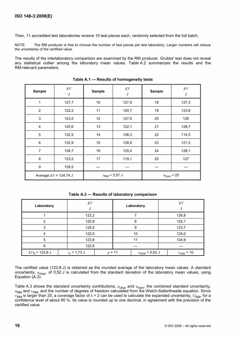
Then, 11 accredited test laboratories receive 10 test pieces each, randomly selected from the full batch.
NOTE The RM producer is free to choose the number of test pieces per test laboratory. Larger numbers will reduce the uncertainty of the certified value.
The results of the interlaboratory comparison are examined by the RM producer. Grubbs' test does not reveal any statistical outlier among the laboratory mean values. Table A.2 summarizes the results and the RM-relevant parameters.
Table A.1 — Results of homogeneity tests
Sample KV J
Sample KV J
Sample KV J
1 127,7 10 127,9 18 127,3
2 122,2 11 120,7 19 123,8
3 123,5 12 127,5 20 126
4 125,6 13 122,1 21 128,7
5 122,5 14 126,3 22 114,5
6 122,9 15 128,9 23 121,3
7 126,7 16 125,4 24 128,1
8 123,2 17 119,1 25 127
9 129,5 — — — —
Average KV = 124,74 J sRM = 3,57 J nhom = 25
Table A.2 — Results of laboratory comparison
Laboratory KV J
Laboratory KV J
1 122,2 7 126,8
2 120,9 8 125,1
3 125,5 9 123,7
4 122,0 10 124,0
5 123,8 11 124,9
6 122,8 — —
KVR = 123,8 J sp = 1,73 J p = 11 uchar = 0,52 J νchar = 10
The certified value (123,8 J) is obtained as the rounded average of the laboratory mean values. A standard uncertainty, uchar, of 0,52 J is calculated from the standard deviation of the laboratory mean values, using Equation (A.3).
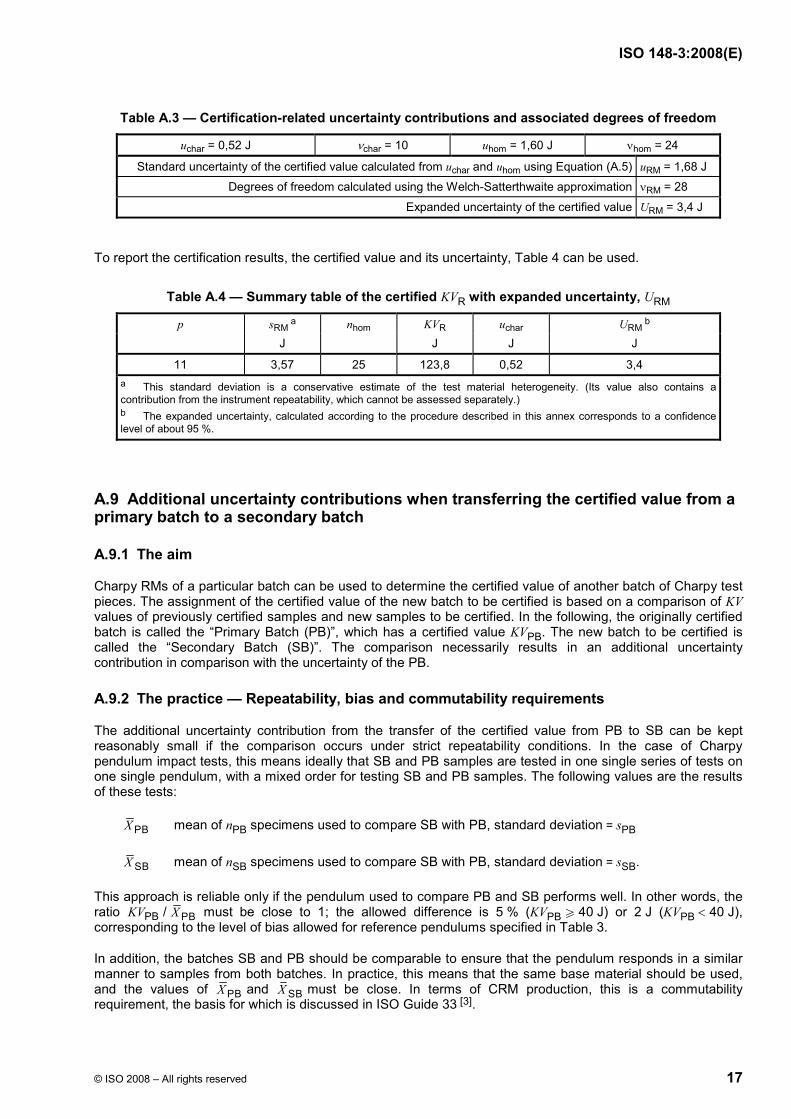
Table A.3 shows the standard uncertainty contributions, uchar and uhom, the combined standard uncertainty, uRM and νRM, and the number of degrees of freedom calculated from the Welch-Satterthwaite equation. Since νRM is larger than 20, a coverage factor of k = 2 can be used to calculate the expanded uncertainty, URM, for a confidence level of about 95 %. Its value is rounded up to one decimal, in agreement with the precision of the certified value.
ISO 148-3:2008(E)
© ISO 2008 – All rights reserved 17
Table A.3 — Certification-related uncertainty contributions and associated degrees of freedom
uchar = 0,52 J νchar = 10 uhom = 1,60 J νhom = 24
Standard uncertainty of the certified value calculated from uchar and uhom using Equation (A.5) uRM = 1,68 J
Degrees of freedom calculated using the Welch-Satterthwaite approximation νRM = 28
Expanded uncertainty of the certified value URM = 3,4 J
To report the certification results, the certified value and its uncertainty, Table 4 can be used.
Table A.4 — Summary table of the certified KVR with expanded uncertainty, URM
p sRM a nhom KVR uchar URM
b J J J J
11 3,57 25 123,8 0,52 3,4 a This standard deviation is a conservative estimate of the test material heterogeneity. (Its value also contains a contribution from the instrument repeatability, which cannot be assessed separately.) b The expanded uncertainty, calculated according to the procedure described in this annex corresponds to a confidence level of about 95 %.
A.9 Additional uncertainty contributions when transferring the certified value from a primary batch to a secondary batch
A.9.1 The aim
Charpy RMs of a particular batch can be used to determine the certified value of another batch of Charpy test pieces. The assignment of the certified value of the new batch to be certified is based on a comparison of KV values of previously certified samples and new samples to be certified. In the following, the originally certified batch is called the “Primary Batch (PB)”, which has a certified value KVPB. The new batch to be certified is called the “Secondary Batch (SB)”. The comparison necessarily results in an additional uncertainty contribution in comparison with the uncertainty of the PB.
A.9.2 The practice — Repeatability, bias and commutability requirements
The additional uncertainty contribution from the transfer of the certified value from PB to SB can be kept reasonably small if the comparison occurs under strict repeatability conditions. In the case of Charpy pendulum impact tests, this means ideally that SB and PB samples are tested in one single series of tests on one single pendulum, with a mixed order for testing SB and PB samples. The following values are the results of these tests:
PBX mean of nPB specimens used to compare SB with PB, standard deviation = sPB
SBX mean of nSB specimens used to compare SB with PB, standard deviation = sSB.
This approach is reliable only if the pendulum used to compare PB and SB performs well. In other words, the ratio PBKV / PBX must be close to 1; the allowed difference is 5 % (KVPB W 40 J) or 2 J (KVPB < 40 J), corresponding to the level of bias allowed for reference pendulums specified in Table 3.
In addition, the batches SB and PB should be comparable to ensure that the pendulum responds in a similar manner to samples from both batches. In practice, this means that the same base material should be used, and the values of PBX and SBX must be close. In terms of CRM production, this is a commutability requirement, the basis for which is discussed in ISO Guide 33 [3].
ISO 148-3:2008(E)
18 © ISO 2008 – All rights reserved
The certified value of the secondary batch, KVSB, is obtained by correcting SBX by a kind of punctual calibration of the pendulum on which the SB and PB were compared, using the ratio PBKV / PB:X
PBSB SB
PB
KVKV XX
= ⋅ (A.8)
where PBKV is the certified KV value of the primary batch.
A.9.3 The resulting uncertainty
To calculate the uncertainty of KVSB, one needs to combine the uncertainties of the factors PB,KV SBX and PBX of Equation (A.8).
a) The value of KVPB links the SB with the results of the PB. In terms of uncertainty, only uchar,PB is relevant, and not uhom, because Equation (A.7) makes the link to the average KV value of the primary batch, not to a set of five samples from the PB.
b) The values SBX and PBX are estimates of the average of SB and PB on the particular pendulum in the particular repeatability conditions, used for the comparison. The standard uncertainty contributions from both factors are
SBSB
SBX
sun
= (A.9)
PBPB
PBX
sun
= (A.10)
NOTE The resolution of the pendulum used contributes to the uncertainties of SBX and PBX as well. However, the pendulums used for this type of comparison are chosen to have a good resolution (0,1 J or better), in which case the resolution does not significantly contribute to SBXu and PBXu .
Since the partial derivatives of Equation (A.8) are all equal to 1 or −1, the uncertainty of the characterization of the SB is obtained by combining the contributions uchar,PB, SBXu and PB.Xu Determine uchar,SB, as follows (see H.6.2 of Reference [7]):
SB PB2 2 2
char,SB char,PB X Xu u u u= + + (A.11)
This uncertainty contribution can be combined with the uncertainty contributions of homogeneity and/or stability, as described in Clause A.8.

ISO 148-3:2008(E)
© ISO 2008 – All rights reserved 19
Bibliography
[1] ISO Guide 30, Terms and definitions used in connection with reference materials
[2] ISO Guide 31, Reference materials — Contents of certificates and labels
[3] ISO Guide 33, Uses of certified reference materials
[4] ISO Guide 34, General requirements for the competence of reference material producers
[5] ISO Guide 35:2006, Reference materials — General and statistical principles for certification
[6] ISO/IEC Guide 98-3, Uncertainty of measurement — Part 3: Guide to the expression of uncertainty in measurement (GUM:1995)
[7] LEVENSON, M.S. et al. An approach to combining results from multiple methods motivated by the ISO GUM. Journal of Research of the National Institute of Standards and Technology, 105(4), 2000, pp. 571-579
[8] PAUWELS, J. et al. European certification of Charpy specimens: reasoning and observations. In Pendulum Impact testing: A Century of Progress. (eds. Siewart, T.A. and Manchan, M.P.) ASTM International, 2000, pp. 90-99
[9] MCCOWAN, C.N. et al. International Comparison of Impact Reference Materials. J. ASTM International, 3(2), 2006, p. 9
[10] ISO 5725-2, Accuracy (trueness and precision) of measurement methods and results — Part 2: Basic method for the determination of repeatability and reproducibility of a standard measurement method
[11] ISO/IEC 17025, General requirements for the competence of testing and calibration laboratories
[12] EN 10045-2, Metallic materials — Charpy impact test — Part 2: Verification of the testing machine (pendulum impact)
[13] ASTM E 23, Standard test methods for notched bar impact testing of metallic materials

ISO 148-3:2008(E)
ICS 77.040.10 Price based on 19 pages
© ISO 2008 – All rights reserved