metalworks f-plank (interior applications)...metalworks™ f-plank (interior applications) assembly...
TRANSCRIPT
METALWORKS™ F-PLANK (Interior Applications)Assembly and Installation Instructions1. GENERAL
1.1 Product Description
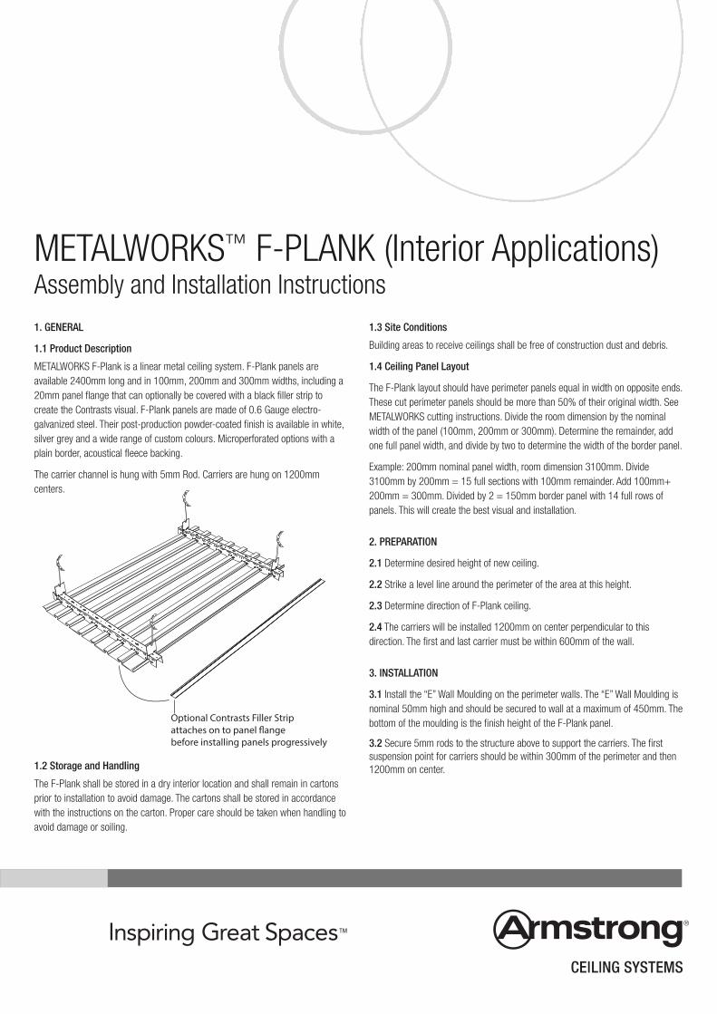
METALWORKS F-Plank is a linear metal ceiling system. F-Plank panels areavailable 2400mm long and in 100mm, 200mm and 300mm widths, including a20mm panel flange that can optionally be covered with a black filler strip tocreate the Contrasts visual. F-Plank panels are made of 0.6 Gauge electro-galvanized steel. Their post-production powder-coated finish is available in white,silver grey and a wide range of custom colours. Microperforated options with aplain border, acoustical fleece backing.
The carrier channel is hung with 5mm Rod. Carriers are hung on 1200mmcenters.
1.2 Storage and Handling
The F-Plank shall be stored in a dry interior location and shall remain in cartonsprior to installation to avoid damage. The cartons shall be stored in accordancewith the instructions on the carton. Proper care should be taken when handling toavoid damage or soiling.
1.3 Site Conditions
Building areas to receive ceilings shall be free of construction dust and debris.
1.4 Ceiling Panel Layout
The F-Plank layout should have perimeter panels equal in width on opposite ends.These cut perimeter panels should be more than 50% of their original width. SeeMETALWORKS cutting instructions. Divide the room dimension by the nominalwidth of the panel (100mm, 200mm or 300mm). Determine the remainder, addone full panel width, and divide by two to determine the width of the border panel.
Example: 200mm nominal panel width, room dimension 3100mm. Divide3100mm by 200mm = 15 full sections with 100mm remainder. Add 100mm+200mm = 300mm. Divided by 2 = 150mm border panel with 14 full rows ofpanels. This will create the best visual and installation.
2. PREPARATION
2.1 Determine desired height of new ceiling.
2.2 Strike a level line around the perimeter of the area at this height.
2.3 Determine direction of F-Plank ceiling.
2.4 The carriers will be installed 1200mm on center perpendicular to thisdirection. The first and last carrier must be within 600mm of the wall.
3. INSTALLATION
3.1 Install the “E” Wall Moulding on the perimeter walls. The “E” Wall Moulding isnominal 50mm high and should be secured to wall at a maximum of 450mm. Thebottom of the moulding is the finish height of the F-Plank panel.
3.2 Secure 5mm rods to the structure above to support the carriers. The firstsuspension point for carriers should be within 300mm of the perimeter and then1200mm on center.
Optional Contrasts Filler Stripattaches on to panel flangebefore installing panels progressively
2
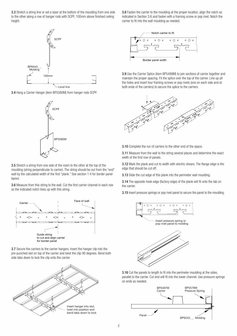
3.3 Stretch a string line or set a laser at the bottom of the moulding from one sideto the other along a row of hanger rods with SCPF, 100mm above finished ceilingheight.
3.4 Hang a Carrier Hanger (item BP5580M) from hanger rods SCPF.
3.5 Stretch a string from one side of the room to the other at the top of themoulding (string perpendicular to carrier). The string should be out from the “end”wall by the calculated width of the first “plank.” See section 1.4 for border panellayout.
3.6 Measure from this string to the wall. Cut the first carrier channel in each rowso the indicated notch lines up with this string.
3.7 Secure the carriers to the carrier hangers. Insert the hanger clip into thepre-punched slot on top of the carrier and twist the clip 90 degrees. Bend bothside tabs down to lock the clip onto the carrier.
3.8 Fasten the carrier to the moulding at the proper location, align the notch asindicated in Section 3.6 and fasten with a framing screw or pop rivet. Notch thecarrier to fit into the wall moulding as needed.
3.9 Use the Carrier Splice (item BP5499M) to join sections of carrier together andmaintain the proper spacing. Fit the splice over the top of the carrier. Line up allthe holes and insert four framing screws or pop rivets (one on each side and atboth ends of the carriers) to secure the splice to the carriers.
3.10 Complete the run of carriers to the other end of the space.
3.11 Measure from the wall to the string several places and determine the exactwidth of the first row of panels.
3.12 Mark the plank and cut to width with electric shears. The flange edge is theedge that should be cut off.
3.13 Slide the cut edge of this plank into the perimeter wall moulding.
3.14 The opposite hook edge (factory edge) of the plank will fit onto the tab onthe carrier.
3.15 Insert pressure springs or pop rivet panel to secure the panel to the moulding.
3.16 Cut the panels to length to fit into the perimeter moulding at the sides,parallel to the carrier. Cut end will fit into the lower channel. Use pressure springson ends as needed.
BP6543_ _Molding
Level line
SCPF
100mm
SCPF
BP5580M
CarrierFace of wall
Guide stringto cut and align carrierfor border panel
Insert hanger into slot,twist into position andbend tabs down to lock
Notch carrier to fit
Border panel width
Insert pressure spring orpop rivet panel to molding
Carrier
BP6543_ _ Molding Panel
Pressure SpringBP5497M BP5576M
3
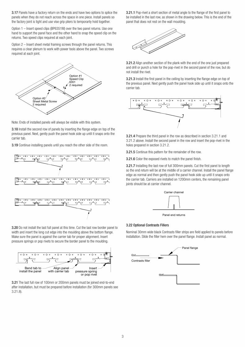
3.17 Panels have a factory return on the ends and have two options to splice thepanels when they do not reach across the space in one piece. Install panels sothe factory joint is tight and use vise grip pliers to temporarily hold together.
Option 1 – Insert speed clips (BP6351M) over the two panel returns. Use onehand to support the panel face and the other hand to snap the speed clip on thereturns. Two speed clips required at each joint.
Option 2 – Insert sheet metal framing screws through the panel returns. Thisrequires a clear plenum to work with power tools above the panel. Two screwsrequired at each joint.
Note: Ends of installed panels will always be visible with this system.
3.18 Install the second row of panels by inserting the flange edge on top of theprevious panel. Next, gently push the panel hook side up until it snaps onto thecarrier tab.
3.19 Continue installing panels until you reach the other side of the room.
3.20 Do not install the last full panel at this time. Cut the last row border panel towidth and insert the long cut edge into the moulding above the bottom flange.Make sure the panel is against the carrier tab for proper alignment. Insertpressure springs or pop rivets to secure the border panel to the moulding.
3.21 The last full row of 100mm or 200mm panels must be joined end-to-endafter installation, but must be prepared before installation (for 300mm panels see3.21.8).
3.21.1 Pop-rivet a short section of metal angle to the flange of the first panel tobe installed in the last row, as shown in the drawing below. This is the end of thepanel that does not rest on the wall moulding.
3.21.2 Align another section of the plank with the end of the one just preparedand drill or punch a hole for the pop-rivet in the second panel of the row, but donot install the rivet.
3.21.3 Install the first panel in the ceiling by inserting the flange edge on top ofthe previous panel. Next gently push the panel hook side up until it snaps onto thecarrier tab.
3.21.4 Prepare the third panel in the row as described in section 3.21.1 and3.21.2 above. Install the second panel in the row and insert the pop-rivet in theholes prepared in section 3.21.2.
3.21.5 Continue this pattern for the remainder of the row.
3.21.6 Color the exposed rivets to match the panel finish.
3.21.7 Installing the last row of full 300mm panels. Cut the first panel to lengthso the end return will be at the middle of a carrier channel. Install the panel flangeedge as normal and then gently push the panel hook side up until it snaps ontothe carrier tab. Carriers are installed on 1200mm centers, the remaining paneljoints should be at carrier channel.
3.22 Optional Contrasts Fillers
Nominal 30mm wide black Contrasts filler strips are field applied to panels beforeinstallation. Slide the filler hem over the panel flange. Install panel as normal.
Option #1Speed Clip63512 required
Option #2Sheet Metal Screw2 required
Align panelwith carrier tab
Bend tab toinstall the panel
Insertpressure spring
or pop rivet
Carrier channel
Panel end returns
Panel flange
Contrasts filler
4
3.23 Optional Panel End Caps
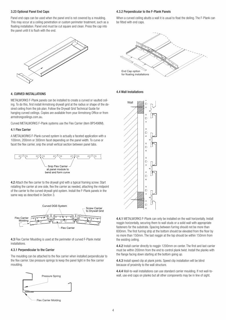
Panel end caps can be used when the panel end is not covered by a moulding.This may occur at a ceiling penetration or custom perimeter treatment, such as afloating installation. Panel end must be cut square and clean. Press the cap intothe panel until it is flush with the end.
4. CURVED INSTALLATIONS
METALWORKS F-Plank panels can be installed to create a curved or vaulted ceil-ing. To do this, first install Armstrong drywall grid at the radius or shape of the de-sired ceiling from the job plan. Follow the Drywall Grid Technical Guide forhanging curved ceilings. Copies are available from your Armstrong Office or fromarmstrongceilings.com.au.
Curved METALWORKS F-Plank systems use the Flex Carrier (item BP5498M).
4.1 Flex Carrier
A METALWORKS F-Plank curved system is actually a faceted application with a100mm, 200mm or 300mm facet depending on the panel width. To curve orfacet the flex carrier, snip the small vertical section between panel tabs.
4.2 Attach the flex carrier to the drywall grid with a typical framing screw. Startnstalling the carrier at one side, flex the carrier as needed, attaching the midpointof the carrier to the curved drywall grid system. Install the F-Plank panels in thesame way as described in Section 3.
4.3 Flex Carrier Moulding is used at the perimeter of curved F-Plank metalinstallations.
4.3.1 Perpendicular to the Carrier
The moulding can be attached to the flex carrier when installed perpendicular tothe flex carrier. Use pressure springs to keep the panel tight in the flex carriermoulding.
4.3.2 Perpendicular to the F-Plank Panels
When a curved ceiling abutts a wall it is usual to float the deiling. The F-Plank canbe fitted with end caps.
4.4 Wall Installations
4.4.1 METALWORKS F-Plank can only be installed on the wall horizontally. Installnoggin horizontally, securing them to wall studs or a solid wall with appropriatefasteners for the substrate. Spacing between furring should not be more than600mm. The first furring strip at the bottom should be elevated from the floor byno more than 150mm. The last noggin at the top should be within 150mm fromthe existing ceiling.
4.4.2 Install carrier directly to noggin 1200mm on center. The first and last carriermust be within 200mm from the end to control plank twist. Install the planks withthe flange facing down starting at the bottom going up.
4.4.3 Install speed clip at plank joints. Speed clip installation will be blindbecause of proximity to the wall structure.
4.4.4 Wall-to-wall installations can use standard carrier moulding. If not wall-to-wall, use end caps on planks but all other components may be in line of sight.
Snip Flex Carrierat panel module to
bend and form curve
Curved DGS System
Flex Carrier
Screw Carrierto Drywall Grid
Flex CarrierMolding
Pressure Spring
Flex Carrier Molding
End Cap optionfor floating installations
Wall
5
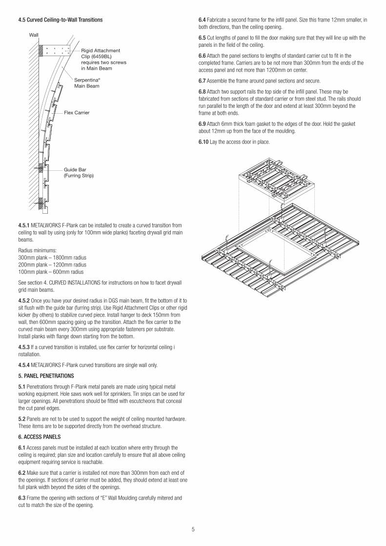
4.5 Curved Ceiling-to-Wall Transitions
4.5.1 METALWORKS F-Plank can be installed to create a curved transition fromceiling to wall by using (only for 100mm wide planks) faceting drywall grid mainbeams.
Radius minimums: 300mm plank – 1800mm radius200mm plank – 1200mm radius100mm plank – 600mm radius
See section 4. CURVED INSTALLATIONS for instructions on how to facet drywallgrid main beams.
4.5.2 Once you have your desired radius in DGS main beam, fit the bottom of it tosit flush with the guide bar (furring strip). Use Rigid Attachment Clips or other rigidkicker (by others) to stabilize curved piece. Install hanger to deck 150mm fromwall, then 600mm spacing going up the transition. Attach the flex carrier to thecurved main beam every 300mm using appropriate fasteners per substrate.Install planks with flange down starting from the bottom.
4.5.3 If a curved transition is installed, use flex carrier for horizontal ceiling installation.
4.5.4 METALWORKS F-Plank curved transitions are single wall only.
5. PANEL PENETRATIONS
5.1 Penetrations through F-Plank metal panels are made using typical metalworking equipment. Hole saws work well for sprinklers. Tin snips can be used forlarger openings. All penetrations should be fitted with escutcheons that concealthe cut panel edges.
5.2 Panels are not to be used to support the weight of ceiling mounted hardware.These items are to be supported directly from the overhead structure.
6. ACCESS PANELS
6.1 Access panels must be installed at each location where entry through theceiling is required; plan size and location carefully to ensure that all above ceilingequipment requiring service is reachable.
6.2 Make sure that a carrier is installed not more than 300mm from each end ofthe openings. If sections of carrier must be added, they should extend at least onefull plank width beyond the sides of the openings.
6.3 Frame the opening with sections of “E” Wall Moulding carefully mitered andcut to match the size of the opening.
6.4 Fabricate a second frame for the infill panel. Size this frame 12mm smaller, inboth directions, than the ceiling opening.
6.5 Cut lengths of panel to fill the door making sure that they will line up with thepanels in the field of the ceiling.
6.6 Attach the panel sections to lengths of standard carrier cut to fit in thecompleted frame. Carriers are to be not more than 300mm from the ends of theaccess panel and not more than 1200mm on center.
6.7 Assemble the frame around panel sections and secure.
6.8 Attach two support rails the top side of the infill panel. These may befabricated from sections of standard carrier or from steel stud. The rails shouldrun parallel to the length of the door and extend at least 300mm beyond theframe at both ends.
6.9 Attach 6mm thick foam gasket to the edges of the door. Hold the gasketabout 12mm up from the face of the moulding.
6.10 Lay the access door in place.
Wall
Serpentina® Main Beam
Flex Carrier
Guide Bar (Furring Strip)
Rigid Attachment Clip (6459BL) requires two screws in Main Beam

MORE INFORMATIONFor complete technical information, detail drawings, CAD design assistance, installation information and many other technical services, call your localArmstrong office.
For the latest product selection and specification data, visit armstrongceilings.com.au
All Trademarks are owned by AWI Licensing Company
NSWArmstrong World Industries Pty. Ltd.99 Derby Street,Silverwater NSW 2128
Telephone (02) 9748 1588Facsimile (02) 9748 8449
VIC/TASArmstrong World Industries Pty. Ltd.29-39 Mills Road,Braeside VIC 3195
Telephone (03) 9580 9633Facsimile (03) 9587 5139
QLD/NTArmstrong World Industries Pty. Ltd.6 Barrinia Street,Slacks Creek QLD 4127
Telephone (07) 3809 5565Facsimile (07) 3809 5507
SATotal Building Systems Pty. Ltd.160 Grand Junction Road,Blair Athol SA 5084
Telephone (08) 7325 7555Facsimile (08) 7325 7566
WACeiling Manufacturers of Australia Pty. Ltd.5 Irvine Street,Bayswater WA 6053
Telephone (08) 9271 0777Facsimile (08) 9272 2801
New ZealandForman Building Systems Ltd.PO Box 12349,Penrose, Auckland
Telephone 64-9-276 4000Facsimile 64-9-276 4141
www.armstrongceilings.com.au
Armstrong, the Global Leader in Acoustic Ceilings
Printed on Zanders Mega Recycled paper ©2015 Armstrong World Industries Pty Ltd. AWP0615
“E” Wall Moulding
Panel
Carrier Rail
Carrier Rail Hanger Bracket
Suspension Clip
Snip Flex Carrier Railat panel module to
bend and form curve
Panel flange
Contrasts filler
Finger side
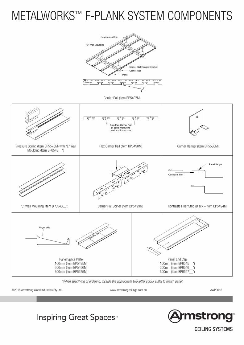
METALWORKS™ F-PLANK SYSTEM COMPONENTS
Carrier Rail (Item BP5497M)
Pressure Spring (Item BP5576M) with “E” WallMoulding (Item BP6543__*)
Flex Carrier Rail (item BP5498M) Carrier Hanger (Item BP5580M)
“E” Wall Moulding (Item BP6543__*) Carrier Rail Joiner (Item BP5499M) Contrasts Filler Strip (Black – Item BP5494M)
Panel Splice Plate100mm (item BP5495M)200mm (item BP5496M)300mm (item BP5575M)
Panel End Cap100mm (item BP6545__*)200mm (item BP6546__*)300mm (item BP6547__*)
* When specifying or ordering, include the appropriate two letter colour suffix to match panel.
©2015 Armstrong World Industries Pty Ltd. www.armstrongceilings.com.au AWP0615