metering technical specifications - city of gold coast | … approval is required if the...
TRANSCRIPT

Metering Technical Specifications
March 2018

Metering Technical Specifications Page 2 of 18
Table of Contents 1. Introduction ................................................................................................................................ 3
1.1 Applying to Council to install water meters ........................................................................ 3
2. Metering technical specifications ............................................................................................. 3 2.1 Water meter types ............................................................................................................. 3 2.2 Water meter serial numbering ........................................................................................... 4 2.3 Master meter ..................................................................................................................... 4
3. Sub-metering specifications ...................................................................................................... 5 3.1 Application and approval ................................................................................................... 5
Sub-meter specifications ................................................................................................... 5 Cold water systems ........................................................................................................... 6 Hot water systems ............................................................................................................ 6 Non drinking water systems .............................................................................................. 6 Installation of sub-meters .................................................................................................. 6 Responsibility for meter asset ownership .......................................................................... 7
3.2 Complex design ................................................................................................................ 7 3.2.1 Detached Dwellings .......................................................................................................... 7 3.2.2 Duplexes ........................................................................................................................... 7 3.2.3 Lots with dual frontage ...................................................................................................... 9 3.2.4 Non-CTS developments constructed under the Manufactured Homes (Residential Parks)
Act 2003 (Qld) ..................................................................................................................11 3.3 Horizontal complexes .......................................................................................................11 3.4 Vertical complexes ...........................................................................................................12 3.5 Mixed use complexes .......................................................................................................12 3.6 Fire Services Metering ...................................................................................................13 3.7 AMR - Automatic Meter Reading ......................................................................................14
Technical requirements ....................................................................................................14 Installation requirements ..................................................................................................14 Electrical requirements .....................................................................................................14
3.8 Enclosures .......................................................................................................................15 Water sub-meter enclosures ............................................................................................15 Water sub-meters in-ground .............................................................................................15 Automatic meter reading enclosures ................................................................................15
3.9 Connectivity audit .............................................................................................................16 Certification of work..........................................................................................................16 Asset handover to the City ...............................................................................................17

Metering Technical Specifications Page 3 of 18
1. Introduction This document provides further additional detail on requirements contained in the Water and Sewerage Connections Policy Procedure. This document sets out the City of Gold Coast Council (City) metering and sub-metering technical requirements.
1.1 Applying to Council to install water meters Depending on the proposed installation location, and type of water meter, Council has multiple application processes required for reviewing applications. Please refer to Section 6 of the City’s ‘Water and Sewerage Connections Policy’ which can be found at cityofgoldcoast.com.au/connections
OPW Approval is required if the installation of meter sizes is 50mm and above (on-lot and above ground). For smaller size meters (20mm – 40mm) this approval is not required.
For all master meter installations an ‘Application to work on the City’s infrastructure’ form is required. The application form can be downloaded from the City’s website at cityofgoldcoast.com.au/connections.
Note: If sub-meters are proposed for the development a Plumbing application must also be submitted to the City’s Plumbing and Drainage directorate.
2. Metering technical specifications
2.1 Water meter types For metering infrastructure (i.e. meter models/types, componentry and AMR systems) currently accepted by the City please visit the ‘South East Queensland Water and Sewerage Design and Construction (SEQ D&C) Code’ and the associated ‘Accepted Civil IPAM List’ website at http://www.seqcode.com.au/products
For water meter standard drawings please visit the City’s website at cityofgoldcoast.com.au/connections
The property owner’s plumber or hydraulic engineer is responsible for sizing the water meter(s) and the type of service(s) required for the property. The City does not make this determination.
Depending on the size and type of service required, either a mechanical or open bore meter must be installed. Generally, mechanical meters are used for domestic services, and open bore electromagnetic or ultrasonic meters are used for fire services or combined fire and domestic services.
Water meters permitted for installation within the City of Gold Coast shall be of the following diameter only:
• 20 millimetre, 25 millimetre, 40 millimetre, 50 millimetre • 100 millimetre, 150 millimetre, 200 millimetre, 250 millimetre, 300 millimetre
Open bore meters are either an ultrasonic or electromagnetic meters. The following information provides advice for the plumber or hydraulic engineer on determining which type of meter (for 100mm and 150mm size services only) to specify for the development:
• Domestic service– Approved mechanical meters. • Dedicated fire service – Either - ARAD Octave Ultrasonic or Siemens Sitrans FM Magflow 8000. • Combined fire and domestic – Either - ARAD Octave Ultrasonic or Siemens Sitrans FM Magflow 8000.

Metering Technical Specifications Page 4 of 18
2.2 Water meter serial numbering Each mechanical meter installed within the City must have an individual serial number specific to that meter and not to be repeated.
The serial number must consist of two numbers identifying the year of manufacture (e.g. 2017 would be 17), two letters specified below identifying the meters nominated size and an individual identification number not exceeding six numbers. Water meters purchased for installation must meet these requirements.
Meter size Letter identifier DN20 W
DN25 X
DN40 E
DN50 HB
DN100 HD
DN150 HF
DN200 HH
DN250 HI
DN300 HJ
2.3 Master meter A master meter shall be installed at the property, complex or development to measure the water supply entering the property. The master meter must be installed to City standards and specifications at the property owners expense. The City will own the meter and be responsible for its maintenance, verification and replacement.
• Meter sizes 20mm to 40mm are to be installed off-lot and below ground
• Meter sizes 50mm and greater are to be installed above-ground and on-lot
Where the master meters are located on-lot the City requires that an easement be created. Please refer to the City’s water meter standard drawings on the City’s website at cityofgoldcoast.com.au/connections
Figure 2.1: Master meter is located on lot and within 2 metres of the property boundary the City will maintain pipework and fittings up to the water meter and inclusive of the meter assembly.

Metering Technical Specifications Page 5 of 18
Figure 2.2: Master meter is located on lot and further than 2 metres from the property boundary the property owner will be responsible for maintaining pipework and fittings up to the meter assembly. The City will own the master meter and be responsible for its maintenance, verification and replacement.
3. Sub-metering specifications
3.1 Application and approval The City uses a standard application and approval process to manage the installation of sub-meters. Further to the Applicants Plumbing & Drainage application being lodged, a “Sub-Meter Assessment Checklist” must be completed in full by the licensed plumber and provided to the City Officer for a sub-meter audit to be conducted.
City Officers from Gold Coast Water and Waste (GCWW) will also conduct a pre-start meeting to ensure proposed installation designs meet City standards and specifications.
The Developer shall submit drawings and hydraulic plans to the City for approval and must include:
• location of each sub-meter in the complex • the make and model of the proposed sub-meters • detailed information regarding the sub meter assembly and arrangement • sub-meter enclosure location and type, and if applicable • details of any AMR equipment and location. The installation of sub-meters will not proceed until the City has approved the application.
The approval of the sub-meters is conditionally linked to the connection approval. The Certificate of Classification will not be issued until the installation of sub-meters and associated AMR system (if applicable) has been installed, commissioned and handed over to the City.
Sub-meter specifications All meters and sub-meters, location and type will require City approval.
The Developer is responsible for the installation of sub-meters. The City’s Plumbing and Drainage section will conduct inspections to make sure the installation has been completed in accordance with the Plumbing and Drainage Act 2002 and AS/NZS 3500.

Metering Technical Specifications Page 6 of 18
• All sub-meters shall be selected from the City's approved water meter list. • All sub-meters shall be installed in the approved City format. • All sub-meters shall be installed in a common or public access area and have unique serial numbers.
• All sub-meters of the same size installed in a complex shall be the same make and model. • Sub-meters shall be installed no higher than 1800 millimetres. • All sub-meters shall have service pipe on the inlet and outlet side of the sub meter assembly (no fittings
connected directly to the assembly). • All sub-meters shall be supplied with an initial reading of 0000kLs • All sub-meters shall be tagged. The tag shall be fixed to the pipework adjacent to the meter or attached to the
meter and have the unit number and meter number displayed in permanent ink. The tag shall not interfere with any data recording equipment if applicable.
• All sub-meters shall be housed in an approved sub-meter enclosure or approved meter pit. • Sub-meters mounted vertically must not be upside down • Slip couplings are to be installed on the inlet side of the sub-meter • Sub-meters are not to be encased in concrete • Sub-meter cupboards are to be bunded (50mm), drained and water-proofed • Wall mounted sub-meters in a designed walkway require a protective shroud • AMR’s shall have one DER panel per building
Cold water systems Sub-meters of 20 millimetres, or in some applications larger sizes if the hydraulic design prescribes, shall be installed within developments to measure individual units and common property water supply.
For developments constructed post 1 January 2008, all sub-meters shall be installed within a development at the time of construction and shall be of the same make and model and have unique serial numbers.
For developments constructed pre 1 January 2008, all sub-meters shall be installed within a development (following applications approval) and shall be of the same make and model and have unique serial numbers.
Hot water systems Where hot water is supplied through individual hot water systems there is no requirement to install a separate sub-meter for each hot water system. The hot water in this situation is measured through the cold water sub-meter.
Where hot water is supplied from a communal hot water system, the system is required to be sub-metered. A sub-meter must be installed on the cold water intake of the communal hot water system and the hot water consumption will be billed to the Body Corporate as common property water consumption.
Non drinking water systems Where developments are in a water dual reticulation area, sub-metering of the non-drinking water supply is required.
Sub-meters used for measuring non-drinking water shall be installed in the approved format and selected from the City’s approved suppliers list.
Sub-meters used for measuring non-drinking water are required to be coloured purple/lilac.
Installation of sub-meters The Developer is responsible for installing the sub-meters. The City’s Plumbing and Drainage section will conduct inspections to make sure installations have been completed in accordance with the Metering Technical Specification, Plumbing and Drainage Act 2002, AS/NZS 3500.1, and the City Plumbing and Drainage approved hydraulic plans.

Metering Technical Specifications Page 7 of 18
Where possible sub-meters shall be grouped together and in a location that is unrestricted at all times. Sub-meters and/or meter boxes are not to be installed/encased in concrete (i.e. driveways, footpaths).
Only licensed plumbers are permitted to install sub-meters in complexes. All work shall be carried out in compliance with all relevant Acts, regulations and by-laws and these technical specifications and guidelines. They should include the:
• Work, Health and Safety Act 2011. • Electricity Supply Act 1994 • AS3000 – SAA Wiring Rules.
On completion of the sub-meter installation, the City will carry out a ‘connectivity audit’ to ensure each unit/lot/storey in the complex is supplied through one sub-meter only and the meter matches the description in the ‘Sub-Meter Assessment Checklist’ and provided to the City Officer at the time of sub-meter audit.
A ‘Sub-Meter Assessment Checklist’ shall also be submitted, completed in full (excluding sub-meter readings) with the request for a connectivity audit.
The as-constructed drawings will include:
• sub-meter serial number and the description of the unit (unit number) supplied through this sub-meter • meter size, make and model • location of sub meters (i.e. enclosure one on ground level) • make and model of any equipment attached to the meter (such as AMR) • size and location of any AMR infrastructure such as aerials, cables and conduits etc. • date of installation
Responsibility for meter asset ownership For developments constructed pre 1 January 2008, pipes or any fittings between the master meter and the sub-meter assembly, the sub-meter assemblies themselves and beyond shall remain the property of the Body Corporate for maintenance and replacement.
For developments constructed post 1 January 2008, the pipes or any fittings between the master meter and the sub-meters shall remain the property of the building owner. The master meter and any AMR system related to the sub-meters and the sub-meter assemblies themselves shall remain the property of the City for maintenance and replacement.
3.2 Complex design 3.2.1 Detached Dwellings Where an additional Class 1 building is approved to be placed on a single title lot then each separate and independent detached or Class 1 dwelling shall have a master meter and water service installed in a similar format to Figure 3.1 and Figure 3.2. This also applies to lots with dual frontage, refer Figure 3.4 to 3.6.
Where a Class 1 building is extended under the same roofline for family accommodation or similar, the lot will be serviced by one master meter only and no approval for a second master meter will be given.
3.2.2 Duplexes Duplexes constructed post 2000 should have had individual water meters in accordance with the City’s Land Development Guidelines at that time (1999).
Metering Technical Specifications Page 8 of 18
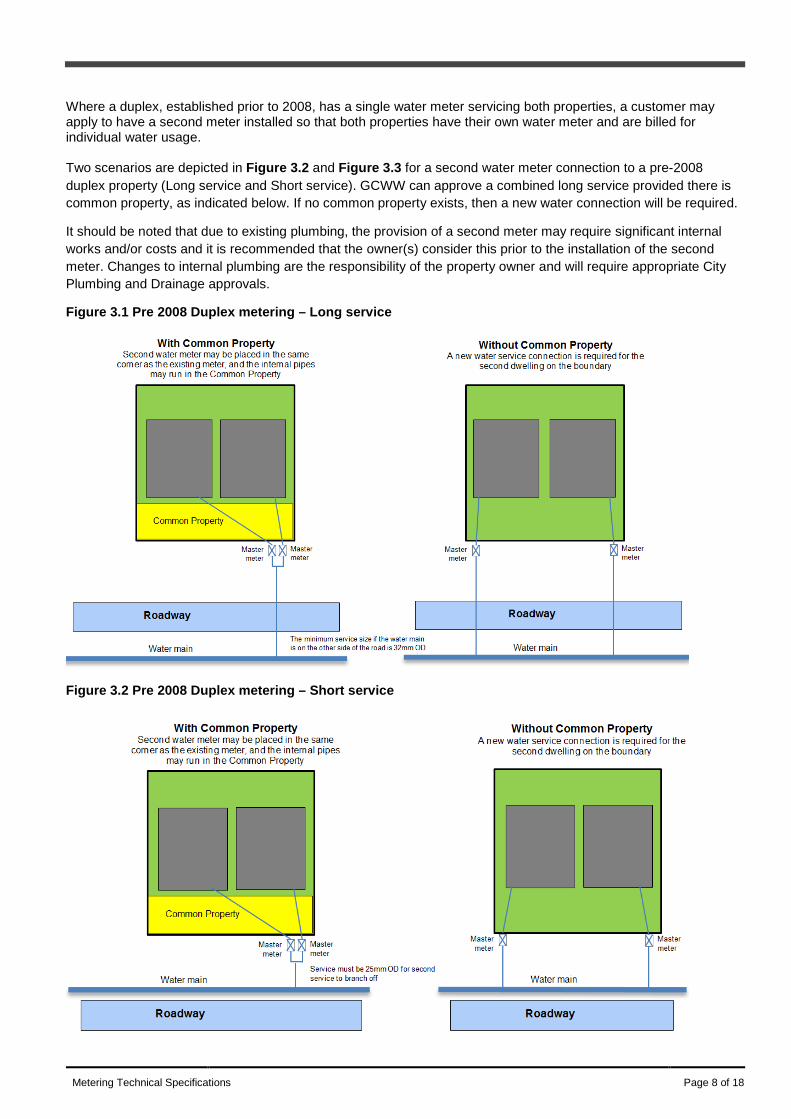
Where a duplex, established prior to 2008, has a single water meter servicing both properties, a customer may apply to have a second meter installed so that both properties have their own water meter and are billed for individual water usage. Two scenarios are depicted in Figure 3.2 and Figure 3.3 for a second water meter connection to a pre-2008 duplex property (Long service and Short service). GCWW can approve a combined long service provided there is common property, as indicated below. If no common property exists, then a new water connection will be required.
It should be noted that due to existing plumbing, the provision of a second meter may require significant internal works and/or costs and it is recommended that the owner(s) consider this prior to the installation of the second meter. Changes to internal plumbing are the responsibility of the property owner and will require appropriate City Plumbing and Drainage approvals.
Figure 3.1 Pre 2008 Duplex metering – Long service
Figure 3.2 Pre 2008 Duplex metering – Short service

Metering Technical Specifications Page 9 of 18
3.2.3 Lots with dual frontage Where there is a second detached dwelling on a lot with dual frontage, there are several situations depending on the development application. These examples are shown below. Single Lot with dual frontage:
Figure 3.3 shows a single lot with dual frontage. The internal on-lot water pipes may run between the Building Envelope and the property boundary. Good practice would be to install the water service in a conduit past the first dwelling. If the owner intends to sell the second dwelling they will need to comply with either Example 2 or Example 3. Figure 3.3 - Single Lot with dual frontage
Community Title Scheme (CTS) with dual frontage:
Figure 3.4 shows two types of CTS developments with dual frontage:
- a standard format lot plus common property - a building format plan
The internal on-lot water pipes will be approved to be laid between the building envelope and the property boundary. An easement is not required for the internal water pipes as the easement is implied under the Body Corporate and Community Management Act. It is suggested that the water service be installed within a conduit to provide some level of protection for the water pipe to pass the forward dwelling. It should be noted that:
- The owner of Lot 2 cannot build any non-removable structures over any implied easement (e.g. internal water pipes)
- In the case of the building format plan allotment if the owner wishes to subdivide in the future they would require a water main extension as shown in Figure 3.6.

Metering Technical Specifications Page 10 of 18
Figure 3.4 - CTS with dual frontage
Reconfiguration of Lot (ROL) Subdivision (Standard format plan) with dual frontage
Figure 3.5 shows an ROL subdivision development with dual frontage. A water main extension is the only acceptable solution. Figure 3.5 - ROL Subdivision with dual frontage

Metering Technical Specifications Page 11 of 18
3.2.4 Non-CTS developments constructed under the Manufactured Homes (Residential Parks) Act 2003 (Qld)
Where a non-CTS development is being constructed and is built under the Manufactured Homes (Residential Parks) Act 2003 (Qld) the following important points apply:
• Sub-meters are required however they will be privately owned • Water and Waste will inspect that sub-meters are installed for each dwelling • Water and Waste will read and issue an account for water consumption for the master meter only • The sub-meters will not be read for billing purposes
3.3 Horizontal complexes Within a horizontal complex development (group housing), sub-meters shall be installed on common property in an accessible area to facilitate direct data acquisition, maintenance and replacement.
In this situation sub-meters will be housed in City approved meter boxes and shall not be installed in locations that pose a risk to the general public (that is, walkways) and the meter box lids shall have a non-slip surface.
If the development is within a dual reticulated area (potable and non-drinking water), sub-meters will also be required.
If sub-meter enclosures are required (i.e. shopping centres) they shall be adequately bunded and drained to the stormwater system to prevent seepage into the infrastructure and all penetrations shall be sealed.
Common property areas must also be sub-metered (that is, designated common areas such as recreation areas, bin wash down areas and common public toilets).
Where a CTS development consists of three or more lots, the development must have a master meter and individual sub-meters, as per Figure 3.1. This scenario also applies where the lots have a common street frontage, refer Figure 3.3. Figure 3.1 Typical sub-meter and master meter set-up in a complex with common property

Metering Technical Specifications Page 12 of 18
Figure 3.3 Metering for CTS with common street frontage
3.4 Vertical complexes Vertical complexes (that is, high rise developments) shall have sub-meters grouped together and installed in an accessible common area to allow direct reading.
The location of the water sub-meter enclosures shall be in a common or public area to allow access to the sub-meters for maintenance or replacement by the appropriate sub-meter owner.
Vertical complexes will require a water sub-meter enclosure to house the sub-meters. In most cases, more than one water sub-meter enclosure will be required for each storey. The sub-meter enclosure shall be adequately bunded and drained to the stormwater system to prevent seepage into the infrastructure and all penetrations shall be sealed.
If the sub-meters are within a fire cabinet enclosure the fire and safety rating shall not be compromised and the water sub-meter enclosure shall be adequately bunded and drained to the stormwater system to prevent seepage into the infrastructure and all penetrations shall be sealed. Sub-meter installation dimensions shall be maintained.
If the development is within a dual reticulated area (potable and non-drinking water), sub-meters will also be required.
Common property areas must also be sub-metered (that is, designated common areas such as recreation areas, bin wash down areas and common public toilets).
3.5 Mixed use complexes Volumetric lots are a form of land tenure provided for under the Land Title Act 1994 (LTA) and refers to three dimensional lots as in multi storey developments. While the lots are freehold, a ‘Building Management Statement’ controls the relationship between the lots. The Building Management Statements are administered by a Building Management Group, which has representation from the participating bodies corporate. An example of a volumetric lot with water and sewage connection and sub-metering is illustrated in Figure 3.4.

Metering Technical Specifications Page 13 of 18
Figure 3.4 An example of a volumetric lot with water and sewage connection and sub-metering to Lot 1
Mixed use complexes (that is, mixed residential and non-residential) shall have a master meter servicing each separate volumetric lot. e.g. a master meter to the residential section and a master meter to the non-residential section. Sub-meters must be grouped together and installed in an accessible, common area to allow direct reading.
Should the residential and non-residential be within a single body corporate then only one master meter is required. Should there be more than one volumetric lot, each volumetric lot needs to have their own master meter.
The location of the water sub-meter enclosures shall be in a common or public area to allow access to the sub-meters for maintenance or replacement. Mixed use complexes will require a water sub-meter enclosure to house the sub-meters. In most cases more than one water sub-meter enclosure will be required.
If the sub meters are to be within a fire cabinet enclosure the fire and safety rating shall not be compromised and the water sub-meter enclosure shall be adequately bunded and drained to prevent seepage into the infrastructure and all penetrations shall be sealed. Sub-meter installation dimensions shall be maintained.
If the development is within a dual reticulated area (drinking and recycled water), sub-meters will also be required.
Common property areas must also be sub-metered (that is, designated common areas such as recreation areas and common public toilets).
3.6 Fire Services Metering All dedicated fire services shall be metered with an open bore Ultrasonic or Electromagnetic water meter. Refer to the Standard Metering Drawing on the City’s website. Backflow prevention shall be provided on all fire services.
Where a Fire Hose Reels is the only part of a Fire Service, it shall be supplied through the domestic service and meter (Refer Section 6 of AS 2441).
Combined Fire and Domestic services or mains in dual reticulation areas will need to be assessed to ensure the correct main is used for fire-fighting. In developments prior to 2008, the potable main was used as the fire-fighting main. Post 2008, a combination of potable and non-drinking water mains are used. The outcome is provisioned with the necessary pressures in the network.

Metering Technical Specifications Page 14 of 18
3.7 AMR - Automatic Meter Reading Where it is deemed that sub-meters cannot be installed in a publicly accessible part of the development due to security restrictions, automatic meter reading (AMR) technology will be required. The installation of an approved AMR system does not take away the requirement for sub-meters to be installed in common or public access areas to allow access to the sub-meters for maintenance or replacement.
Where the developer is required to install an AMR system, it must be a City approved type. Only AMR systems and suppliers approved by the City may be used. Refer to Standard Drawing 11-133 on the City website at cityofgoldcoast.com.au/connections
A 12 month warranty on all AMR components will be provided by the AMR manufacturer/supplier and also the approved technician’s workmanship from the date of installation. Prior to the 12 month warranty period expiring, City Officers will inspect the system and, if necessary, advise the manufacturer/supplier of any defects which the approved technician will be required to rectify within 21 days.
Technical requirements The AMR system shall incorporate only one digital electronic reader (DER) panel to be installed for each building within the complex in an accessible location. The location requirements for the DER enclosure are to be approved by City Officers. When an AMR system is used, the master meter and all sub-meters must be linked to the AMR to enable the meter reading data to be sent to the DER panel.
Installation requirements The AMR installation shall be provided by a qualified technician approved by the AMR provider and must take responsibility for all components of the AMR installation including, but not limited to, power supply cabling, meter reed switch installation and meter communication from the meter/s to the DER panel.
The installation of the AMR will not remove the ability to enable a manual read of each sub-meter.
A full set of sub-meter hydraulic and electrical as-constructed drawings must be submitted to the City in addition to those submitted as a part of the plumbing and drainage processes.
Electrical requirements The electrical installation of the AMR and connection to sub-meters shall be in accordance with AS3000, AS3008 and all relevant Australian Standards, supply authority regulations and statutes.
All on site cabling and conduit is to be installed by the developer. All reed switch cabling from meters is to be CAT5E minimum rated and each pair used from each cable is to be correctly labelled with the number at the end of each pair. Where a manufacturer requires a different cable type (such as the Layson 2TPS for the Epitomy system) this cable shall be supplied and installed and labelled similarly. CAT5E cable must be sourced from a supplier that can certify that the cable is compliant with ANSI/TIA/EIA-568-A CAT5E specifications. Cable inclusive of a nylon spine is preferred.
All cables must be mechanically protected and not be subjected to movement or stretching of any kind. Cable should follow cable duct routes and have a minimum clearance of 300mm from power conductors.
Knife type encapsulated connectors must not be used on ‘stranded’ core cables and can only be used on single core wire and be approved by the AMR system supplier. Soldered and double heat shrunk insulation is the preferred method of connection. Connections that prevent water ingress are preferred. Cable runs should not be exposed to water spray or rain unless enclosed in conduit. The method of connection shall be approved by the City.
Backbone communication cables between data gathering units (data loggers, data units, etc) and the digital electronic read (meter display units, meter processor, interface panel, etc) should have a minimum of 2 spare pairs.
Standard drawing 11-133 can be downloaded from cityofgoldcoast.com.au/connections and provides the City’s minimum requirement for AMR cabling and associated wiring and connections standards.

Metering Technical Specifications Page 15 of 18
3.8 Enclosures Water sub-meter enclosures The location of the water sub-meter enclosure is to be installed in a common or public access area.
The enclosure shall be marked clearly ‘Water Sub-Meters’ on the outside of the door. Where more than one sub-meter enclosure is installed, each enclosure shall have an ID number on the cabinet as shown in the standard drawing.
If the sub meters are to be within a fire cabinet enclosure the fire and safety rating shall not be compromised and the water sub-meter enclosure shall be adequately bunded and drained to prevent seepage into the infrastructure and all penetrations shall be sealed. Sub-meter installation dimensions shall be maintained.
The sub-meter enclosure shall be adequately bunded and drained to the stormwater system to prevent seepage into the infrastructure and all penetrations shall be sealed.
A minimum area of two-square metres or an area of 1.5 metres x door width (whichever is greater) shall be provided directly at the enclosure for maintenance and customer interaction.
The enclosure shall have adequate lighting without the need for additional aids such as ladders to read or maintain meters.
Any enclosure door/s in a pedestrian pathway or high use area shall have a one point stainless steel quarter turn latch flush mounted. The enclosure material shall be either one millimetre thick steel or 1.5 millimetre 5251 or 5083 alloy aluminium, and powder-coated to suit building architecture and shall be in accordance with the standard drawings.
All external edges are to be rounded with all edges and corners accurately and neatly folded. Enclosure door/s shall have a hand operated one point stainless steel quarter turn latch to close the door and shall have lift off type plated brass hinges with stainless steel hinge pins.
If a lock is fitted to the exterior door/s it needs to use a standard common C4 keyway cut to 34284.
Water sub-meters in-ground The sub-meter assembly shall be installed within a City approved meter box with a non-slip lid.
Bedding or soil shall not surround or cover any components within the meter box. Sub-meter assemblies shall not be installed within concrete or roadways or be encapsulated within concrete.
The meter capsules reading dial shall be no more than 300 millimetre from the surface level.
Automatic meter reading enclosures Any development that requires an AMR system will install an accessible enclosure to house the water meter digital electronic reading panel, the DER panel.
The location of the DER panel enclosure is to be in a public access area. The DER panel enclosure shall be clearly marked ‘Water Meter Data’ with a minimum lettering height of 25 millimetre and be permanently fixed in the centre to the outside of the door.
The DER panel displays shall be installed no higher than 1800 millimetre and no lower than 1200 millimetre. A minimum area of two square metres or an area of 1.5 metres x door width (whichever is greater) shall be provided directly at the enclosure for maintenance and customer interaction.
The enclosure shall have adequate lighting and not require additional aids (i.e. ladders) to obtain meter data.
The DER panel enclosure shall be sealed so as not to expose the DER panel to the elements (i.e. sunlight, wind rain). The DER panel enclosure doors shall have a locking system capable of exerting sufficient pressure to

Metering Technical Specifications Page 16 of 18
ensure proper contact of the sealing medium all around the door with lift off type hinges, chrome plated solid brass body (80 millimetre minimum length) with stainless steel hinge pins.
Any enclosure door/s that are in a pedestrian pathway or high use area shall have a one point stainless steel quarter turn latch flush mounted.
A lock shall be fitted to the exterior door of the DER panel enclosure and the lock needs to use a standard common C4 keyway cut to 34284.
The DER panel enclosure shall house a lockable 240-volt electrical power supply outlet for AMR system use within 300 millimetre of the meter read panel (and when required to power additional logger boxes).
The DER panel enclosure shall contain a draw wire back to a telecommunication connection point for AMR system use. The conduit shall be connected to the meter read panel.
The DER panel enclosure shall be sufficiently ventilated and rated to IP65. The material of any external DER panel enclosure shall be either minimum two millimetre thick 316 grade stainless steel or three millimetre 5251 or 5083 alloy aluminium powder coated colour Beige AS 2700S-1996 (X43) or matched to suit building architecture.
All external edges are to be rounded with all edges and corners accurately and neatly folded.
3.9 Connectivity audit The City will conduct the connectivity audit following advice the installation has been completed in accordance with Plumbing and Drainage Act 2002, AS/NZS 3500.1 and with the approved hydraulic drawings. The connectivity audit will verify that:
• sub-meters are accessible for reading and maintenance • the serial number on the sub-meter matches serial number on the sub-meter assessment checklist • each sub-meter is correctly installed, tagged appropriately and only measuring flow to the designated particular
unit/lot/storey/common area.
If the connectivity audit reveals that a sub-meter has not been correctly installed, the developer shall investigate and remove any cross connections and mismatches, prepare new as-constructed drawings and apply for another connectivity audit.
If an AMR system has been installed, the AMR system must be fully commissioned and proven to be working by providing accurate readings from all sub-meters in the complex. This will be confirmed by the City at the time of AMR commissioning and connectivity audit.
Certification of work Final plumbing and drainage approval for the development will not occur independently of the connectivity audit for the development. A plumbing final will not be issued until sub-meters have been passed by City Officers.
For post 1 January 2008 developments, when the connectivity audit is successful, the City will advise the development that it can be issued with the Building Certifier’s Certificate of Classification that all sub-metering and other requirements have been successfully completed.
At the completion of the connectivity audit, a copy of the approved hydraulic, AMR electrical and as-constructed drawings, schematic of metering set-up and the ‘Sub-Meter Assessment Checklist’ will remain with the City. This checklist will be used to provide the relevant information to link each sub-meter with its respective unit/lot in the water billing system.
For pre 1 January 2008 developments, when the connectivity audit is successful, we will accept the assessment checklist – sub-meter data and all associated as-constructed information. This checklist will be used to provide the relevant information to link each private sub-meter with its respective unit/lot in the water billing system.

Metering Technical Specifications Page 17 of 18
Asset handover to the City For new developments (post 1 January 2008), once the final connectivity audit for the development has been successfully completed, the ownership of sub-meter assemblies, the sub-meter isolation valves and any AMR system infrastructure (if required) will transfer to the City.
For pre 1 January 2008 developments, once the final connectivity audit for the development has been successfully completed, the ownership of sub-meter assemblies, the sub-meter isolation valves and any AMR system infrastructure associated with the sub-meters will remain the private property of the Body Corporate.
A 12 month warranty on all AMR components will be provided by the AMR manufacturer/supplier and also the approved technician’s workmanship from the date of installation. Prior to the 12 month warranty period expiring, the City will inspect the system and if necessary advise the manufacturer/supplier of any defects which the approved technician will be required to rectify within a timeframe determined by the City.

Metering Technical Specifications Page 18 of 18
For more information P 1300 GOLDCOAST (1300 465 326) W cityofgoldcoast.com.au