methanol steam reformer high temperature pem fuel cell ... - miltary green 2012 - methanol...
TRANSCRIPT

19 – 20 June 2012
Brussels, Belgium
Military Green 2012
Conference-Exhibition-Demonstration Call for Exhibits and Demonstrations
Methanol Steam Reformer – High Temperature PEM Fuel Cell
System Analysis
Andrej LOTRIČ (Mebius d.o.o., Na jami 3, SI-1000 Ljubljana, Slovenia) and Stanko HOČEVAR
(Mebius d.o.o., Na jami 3, SI-1000 Ljubljana, Slovenia and National Institute of Chemistry, Lab.
Catal. & Chem.React.Eng., Hajdrihova 19, SI-1000 Ljubljana, Slovenia)
The implementation of a high-temperature PEMFC stack into a combined system with a steam
methanol reformer (SMR) has been studied. Comparison of efficiency between systems with a
high temperature (HT) PEMFC stack and a classical, low-temperature (LT) PEMFC stack has been
made. In both systems the methanol reformer operates at 250 °C and steam-to-methanol ratio of
1.5. Classical PEMFC stack operates at 90 °C while high-temperature PEMFC stack operates at
250 °C. Additionally, the system with a classical PEMFC stack uses a catalytic burner to supply
the endothermal reforming process with sufficient heat. Partial heat regeneration has been also
used in this system because hot exhaust gases from the reformer need to be cooled down before
entering the fuel cell stack. Modelling of both systems and sensitivity analysis was performed in
Aspen Plus. The results show that efficiency of approximately 54% (based on higher heating
value) can be reached with the HT PEMFC system, which is more than 40% higher efficiency
compared to the LT PEMFC system.
1 Introduction
One of the major constraints for the PEMFC is that they use hydrogen as a fuel which has a very
low energy density per volume at conditions of standard ambient pressure and temperature
(SAPT). Therefore hydrogen is stored either as gas at very high pressures (up to 800 bar) or as
liquid at very low temperatures below -253 °C. As an alternative the reforming of liquid fuels
(fossil or renewable) is showing promise because they have much higher energy density per
volume. For small portable applications methanol shows good potential because it is sulphur free,
has a high hydrogen-to-carbon ratio in its composition and is in liquid form at SAPT, which greatly
facilitates its storage and transportation. It can be seen from Table 1 that at SAPT methanol has
more than thousand times greater energy density per volume compared to hydrogen.
Table 1: Higher heating value (HHV) of hydrogen at different conditions and methanol at SAPT
Hydrogen Methanol Ratio
141.9 kJ/g 20.0 kJ/g 7.1 : 1
SAPT 11.5 kJ/L
15.7 MJ/L
1 : 1,365
800 bar 6.0 MJ/L 1 : 2.6
-253 °C 10.1 MJ/L 1 : 1.6
Another shortcoming of PEMFC is that the heat released during the electrochemical reaction is on
relatively low temperature level and it is mostly discarded as waste heat. This is one of the main
Annex 3 to EDA Comm N° 12/027

19 – 20 June 2012
Brussels, Belgium
Military Green 2012
Conference-Exhibition-Demonstration Call for Exhibits and Demonstrations
reasons that the research is also starting to focus on the so called high-temperature PEMFC,
which could operate at temperatures higher than 200 °C. This would allow the reaction kinetics
to proceed faster and consequently raise the efficiency of PEMFC and at the same time allow the
use of waste heat in cogeneration for different applications.
As it turns out, raising the temperature above 200 °C would have another advantage. The
reformate gas exiting the steam reformer always contains some carbon monoxide (CO) which is
the main inhibitor of electrochemical reaction in PEMFC. The reason for that is the preferential
adsorption of CO onto the active sites of the platinum (Pt) catalyst. At higher temperatures this
occurs at a much lesser extent and the HT PEMFC operating above 200 °C could work normally
at concentrations higher than 2% of CO in the inlet gas (based on [1]). With good design of the
steam reformer such composition of the reformate gas is not too difficult to achieve. This would
also remove the need for downstream hydrogen purification processes (WGSR, PrOX or
methanation) and reduce the costs substantially.
Increasing the temperature of PEMFC operation above 250 °C would have an additional benefit
because the heat released during the electrochemical reaction would be on a sufficiently high
level to support steam reforming of methanol. The steam reforming process can achieve
practically 100% conversion of methanol at temperatures between 250 °C – 300 °C. This
depends on the design of reformer. The integrated system with such HT PEMFC stack would have
higher efficiency compared to the LT PEMFC because it would not need a catalytic burner to
supply continuously the SMR with additional heat for the reforming of methanol.
2 System modelling
Modelling of the SMR was based on the kinetic model proposed by Peppley et al [2]. The kinetics
was included directly into Aspen plus using the R-Plug model unit with Langmuir-Hinshelwood
kinetic model.
The model of a PEMFC was based on calculations from an in-house developed model in
SIMULINK. The results from SIMULINK model were integrated into Aspen Plus User-2 model of
PEMFC downloaded from Aspen support site.
2.1 Methanol reformer
To describe properly the methanol conversion as a function of temperature we have used the
kinetic model proposed by Peppley et al [2]. The same kinetic model was also used in a study
made by Pattekar and Kothare [3] and in a study made by Telotte et al [4]. Comparing all the
articles there were some minor mistakes found in equations and some discrepancies in
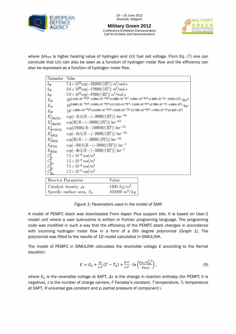
parameters. The values used in our model of the SMR are presented on Figure 1.
The kinetic model presumes that in the SMR three reactions proceed simultaneously: steam
methanol reforming (Eq. (1)), direct decomposition of methanol (Eq. (2)), and water gas shift
reaction (Eq. (3)):
CH3OH + H2O ↔ CO2 + 3H2 , (1)

19 – 20 June 2012
Brussels, Belgium
Military Green 2012
Conference-Exhibition-Demonstration Call for Exhibits and Demonstrations
CH3OH ↔ CO + 2H2 , (2)
CO + H2O ↔ CO2 + H2 . (3)
The rate of reaction ri depends on the rate limiting step in its set of elementary reaction steps. The
process of steam reforming is a combination of all three reaction sets therefore it is given in the
form of the following equations:
(
) (
)
( (
)
(
)) (
)
, (4)
(
) (
)
( (
) (
)) (
)
, (5)
(
) (
)
( (
)
(
))
, (6)
Eqs. (4)-(6) where used in Aspen Plus process modelling software where R-Plug model unit was
used as a SMR. The reactions where integrated into the unit in the form of Langmuir-Hinshelwood
kinetics. The reactor is modelled as a plug flow tubular reactor which means that there is no
change of thermodynamic properties in radial direction (no concentration, temperature and
pressure gradients) but the changes exist in the axial direction. The reactor is designed as a tube
of 150 mm length and 10 mm diameter.
2.2 Fuel Cell Stack
The efficiency of PEMFC depends on the generated current density j, which is directly
proportional to the molar flow of used reactants via the Faraday’s law of electrolysis:
, (7)
where I represents electrical current, A active surface area of PEMFC, z number of charge carriers
and F Faraday’s constant. In general, the efficiency of an energy system is defined as a ratio
between energy supplied to the system and energy produced by the system. In terms of PEMFC
the efficiency can be deduced as:
, (8)
19 – 20 June 2012
Brussels, Belgium
Military Green 2012
Conference-Exhibition-Demonstration Call for Exhibits and Demonstrations
where ∆HHHV is higher heating value of hydrogen and U(I) fuel cell voltage. From Eq. (7) one can
conclude that U(I) can also be seen as a function of hydrogen molar flow and the efficiency can
also be expressed as a function of hydrogen molar flow.
Figure 1: Parameters used in the model of SMR
A model of PEMFC stack was downloaded From Aspen Plus support site. It is based on User-2
model unit where a user subroutine is written in Fortran programing language. The programing
code was modified in such a way that the efficiency of the PEMFC stack changes in accordance
with incoming hydrogen molar flow in a form of a 6th degree polynomial (Graph 1). The
polynomial was fitted to the results of 1D model calculated in SIMULINK.
The model of PEMFC in SIMULINK calculates the reversible voltage E according to the Nernst
equation:
(
) , (9)
where is the reversible voltage at SAPT, is the change in reaction enthalpy (for PEMFC it is
negative), z is the number of charge carriers, F Faraday’s constant, T temperature, T0 temperature
at SAPT, R universal gas constant and pi partial pressure of component i.
19 – 20 June 2012
Brussels, Belgium
Military Green 2012
Conference-Exhibition-Demonstration Call for Exhibits and Demonstrations
There are several factors that affect the reversible voltage in form of losses. Three major types of
losses occur in PEMFC as a result of slow kinetics on electrodes (activation losses), depletion of
reactant concentrations due to mass transport (concentration losses) and poor conductivity of
protons through the polymer membrane (ohmic losses). These losses are subtracted from the
reversible cell potential to obtain the characteristic polarisation curve of the PEMFC.
The kinetics of electrochemical reaction in PEMFC is described by the Butler-Volmer equation:
(
) , (10)
where is the transfer coefficient and are the activation losses. If it is assumed that
the Euler equation can be used and activation losses can be deduced as:
(
) , (11)
where j is the current density of PEMFC and j0 the exchange current density. The contribution to
activation losses is only calculated on the cathode side because the kinetics on the cathode side
is much slower than that on the anode side. The same situation stands for the concentration
losses, which are far greater on the cathode side than on the anode side, especially when air is
used as an oxidant. Concentration losses are calculated as:
(
) (
) , (12)
where jL is the limiting current of the PEMFC. Ohmic losses are defined according to Ohm’s
law and can be written as:
, (13)
where stands for thickness, for active surface area and for proton conductivity of the
membrane. It is assumed that all the other ohmic losses originating from stack components
contact resistances are negligible.
At this point it needs to be mentioned that LT and HT PEMFC use the same characteristic curve
for the stack efficiency even though it is clear that they will be different. Despite the fact that at
higher temperature the equilibrium potential of PEMFC is lower the efficiency will be higher due to
faster kinetics on the electrodes.
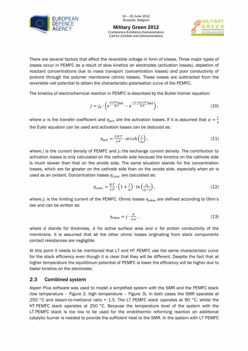
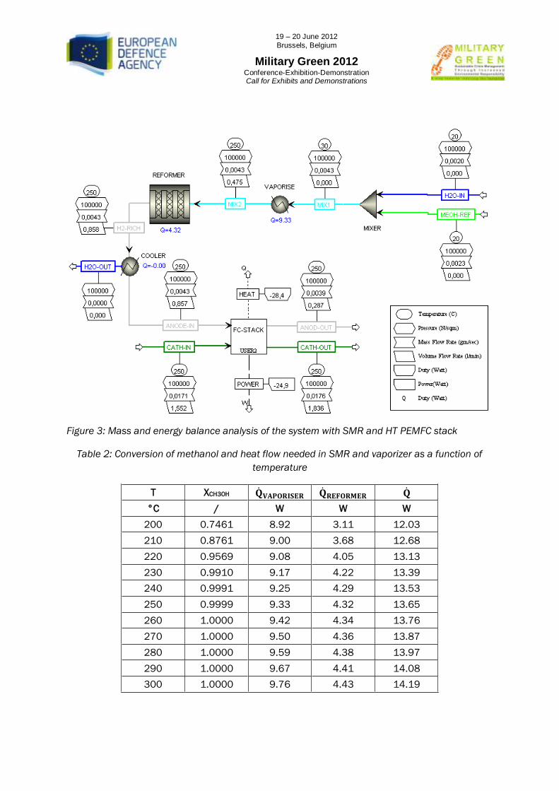
2.3 Combined system
Aspen Plus software was used to model a simplified system with the SMR and the PEMFC stack
(low temperature – Figure 2, high temperature – Figure 3). In both cases the SMR operates at
250 °C and steam-to-methanol ratio = 1.5. The LT PEMFC stack operates at 90 °C, whilst the
HT PEMFC stack operates at 250 °C. Because the temperature level of the system with the
LT PEMFC stack is too low to be used for the endothermic reforming reaction an additional
catalytic burner is needed to provide the sufficient heat to the SMR. In the system with LT PEMFC

19 – 20 June 2012
Brussels, Belgium
Military Green 2012
Conference-Exhibition-Demonstration Call for Exhibits and Demonstrations
partial heat regeneration is also used from hot exhaust gases exiting the reformer to the vaporiser
of water methanol mixture.
Graph 1: Efficiency curve of PEMFC obtained from SIMULINK model
In presented SMR and PEMFC stack systems there are some assumptions and idealisations that
need to be mentioned:
adiabatic insulation of PEMFC stack and SMR
ideal heat transfer between PEMFC stack and SMR (no losses)
100% methanol conversion in SMR
100% utilisation of hydrogen on anode side of PEMFC stack
no scrubbing of gases exiting the reformer is considered (this is important particularly in
the case of LT PEMFC CO poisoning)
PEMFC stack operates at the same efficiency and nominal electric power of 25 W in both
cases, the difference is only in the temperature level of generated heat
y = -0,0003x6 + 0,0039x5 - 0,0143x4 + 0,0062x3 + 0,0712x2 - 0,1981x + 0,6617
0,2
0,25
0,3
0,35
0,4
0,45
0,5
0,55
0,6
0,65
0,7
0 0,5 1 1,5 2 2,5 3 3,5 4 4,5 5 5,5
η [
/]
H2 molar flow [10-4 mol/s]
Efficiency of PEMFC as a function of H2 molar flow

19 – 20 June 2012
Brussels, Belgium
Military Green 2012
Conference-Exhibition-Demonstration Call for Exhibits and Demonstrations
Figure 2: Mass and energy balance analysis of the system with SMR and LT PEMFC stack
3 Results
3.1 Methanol reformer
Based on the assumption that the system produces 25 W of electricity and that 100% methanol
conversion is achieved it was calculated that 7.3·10-5 mol/s of methanol would be needed to
supply sufficient hydrogen flow to the PEMFC stack. At the specified molar flow and based on
reforming kinetics and dimensions of the reactor (see chapter 2.1) the sensitivity analysis of
methanol conversion as a function of temperature was performed (Table 2). Also the heat flow
needed for the reforming reaction and for the vaporisation of water-methanol mixture was
evaluated.
19 – 20 June 2012
Brussels, Belgium
Military Green 2012
Conference-Exhibition-Demonstration Call for Exhibits and Demonstrations
Figure 3: Mass and energy balance analysis of the system with SMR and HT PEMFC stack
Table 2: Conversion of methanol and heat flow needed in SMR and vaporizer as a function of
temperature
T XCH3OH
°C / W W W
200 0.7461 8.92 3.11 12.03
210 0.8761 9.00 3.68 12.68
220 0.9569 9.08 4.05 13.13
230 0.9910 9.17 4.22 13.39
240 0.9991 9.25 4.29 13.53
250 0.9999 9.33 4.32 13.65
260 1.0000 9.42 4.34 13.76
270 1.0000 9.50 4.36 13.87
280 1.0000 9.59 4.38 13.97
290 1.0000 9.67 4.41 14.08
300 1.0000 9.76 4.43 14.19
19 – 20 June 2012
Brussels, Belgium
Military Green 2012
Conference-Exhibition-Demonstration Call for Exhibits and Demonstrations
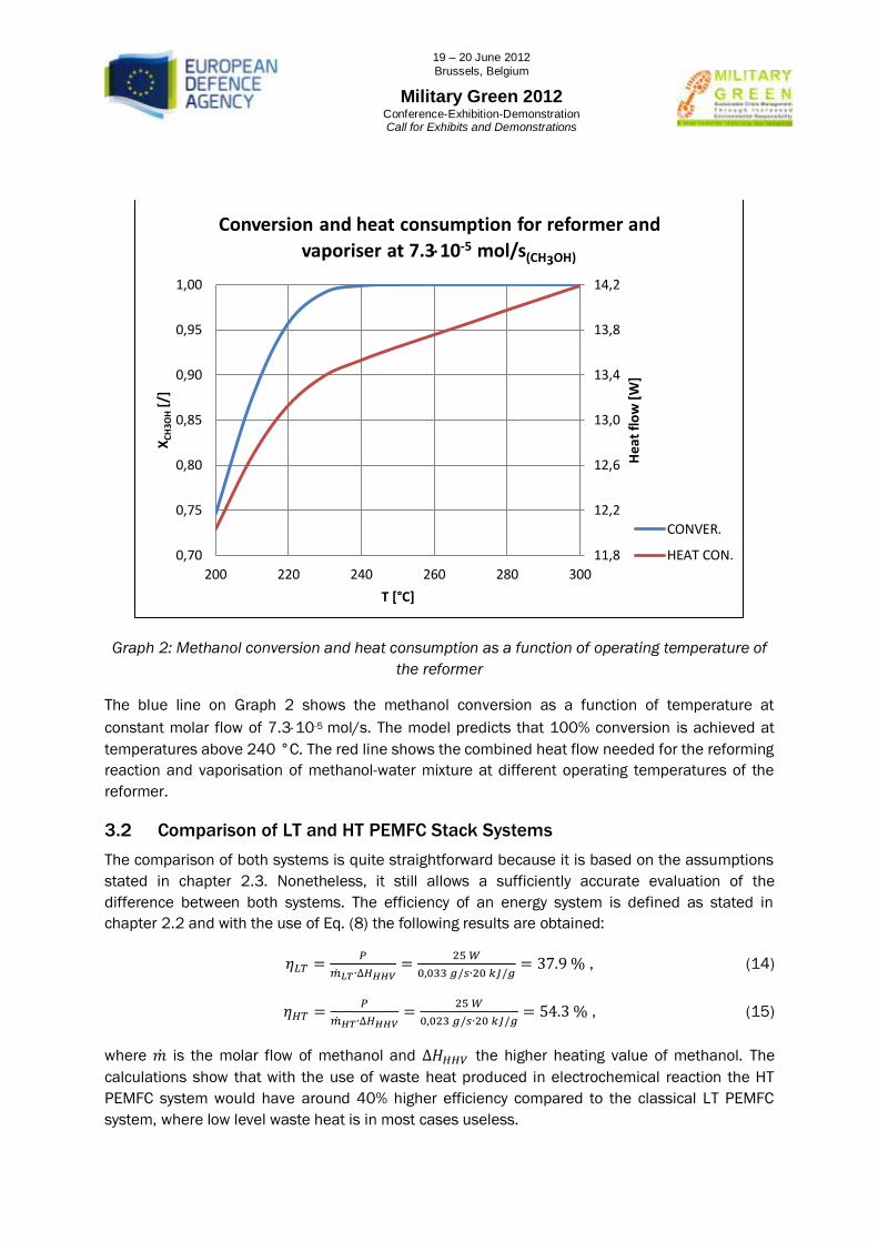
Graph 2: Methanol conversion and heat consumption as a function of operating temperature of
the reformer
The blue line on Graph 2 shows the methanol conversion as a function of temperature at
constant molar flow of 7.310-5 mol/s. The model predicts that 100% conversion is achieved at
temperatures above 240 °C. The red line shows the combined heat flow needed for the reforming
reaction and vaporisation of methanol-water mixture at different operating temperatures of the
reformer.
3.2 Comparison of LT and HT PEMFC Stack Systems
The comparison of both systems is quite straightforward because it is based on the assumptions
stated in chapter 2.3. Nonetheless, it still allows a sufficiently accurate evaluation of the
difference between both systems. The efficiency of an energy system is defined as stated in
chapter 2.2 and with the use of Eq. (8) the following results are obtained:
, (14)
, (15)
where is the molar flow of methanol and the higher heating value of methanol. The
calculations show that with the use of waste heat produced in electrochemical reaction the HT
PEMFC system would have around 40% higher efficiency compared to the classical LT PEMFC
system, where low level waste heat is in most cases useless.
11,8
12,2
12,6
13,0
13,4
13,8
14,2
0,70
0,75
0,80
0,85
0,90
0,95
1,00
200 220 240 260 280 300
He
at f
low
[W
]
XC
H3O
H [
/]
T [°C]
Conversion and heat consumption for reformer and
vaporiser at 7.310-5 mol/s(CH3OH)
CONVER.
HEAT CON.

19 – 20 June 2012
Brussels, Belgium
Military Green 2012
Conference-Exhibition-Demonstration Call for Exhibits and Demonstrations
The main characteristics of the two systems working at nominal operating point are given in Table
3. The cause of small difference in heat and power produced is in difference of the temperature
of the reformate gas. Reformate gas entering the LT PEMFC stack at 90 °C has lower enthalpy
and hence less energy is available to produce power and/or heat. The difference in consumed
heat flow is only due to the heat regeneration of reformate gas; otherwise the same amount of
heat is consumed in the SMR and vaporiser.
Table 3: Main characteristics of LT and HT PEMFC systems
Stack Operating
temperature Power
Produced
heat flow
Consumed
heat flow
Additional
heat flow Efficiency
LT 90 °C 24.7 W 28.2 W 11.9 W 11.9 W 37.9%
HT 250 °C 24.9 W 28.4 W 13.6 W 0 W 54.3%
Sensitivity analysis of the HT PEMFC system as a function of methanol molar flow was performed.
In that case the temperature of SMR and HT PEMFC was held constant at 250 °C.
Graph 3: Heat & Power produced in HT PEMFC, Heat consumption in reformer & vaporiser, and
CH3OH conversion at T = 250 °C
0 0,2 0,4 0,6 0,8 1 1,2
0,990
0,992
0,994
0,996
0,998
1,000
0
10
20
30
40
50
60
70
80
90
100
0 0,2 0,4 0,6 0,8 1 1,2 1,4 1,6 1,8
j [A/cm2]
XC
H3O
H [
/]
Hea
t fl
ow
|Po
we
r [W
]
CH3OH molar flow [10-4 mol/s]
Heat & Power produced in HT PEMFC stack, heat consumption in reformer & vaporiser, and CH3OH conversion at T = 250°C
HEATprod
POWER
HEATcons
CONVER.
28.4 W
24.9 W
0.73
13.7 W

19 – 20 June 2012
Brussels, Belgium
Military Green 2012
Conference-Exhibition-Demonstration Call for Exhibits and Demonstrations
On Graph 3 the red line represents the heat flow produced by the HT PEMFC, the blue line
represents the power produced by the HT PEMFC and the orange line represents the heat flow
needed to supply the SMR and the vaporiser. The green line represents the conversion of
methanol where it can be seen that at molar flow 7.3·10-5 mol/s of methanol the reformer still
achieves practically 100% conversion. Increasing the molar flow above this value reduces the
conversion; however it is still well above 99% even at peak power of the HT PEMFC.
If nominal operating point is selected at conditions of methanol molar flow 7.3·10-5 mol/s and
temperature 250 °C, the system produces 24.9 W of electricity, 28.4 W of heat flow and
consumes 13.7 W of heat flow. Under the assumptions stated in chapter 2.3 this would mean
that the system has the potential to produce more than twice as much heat as needed for the
SMR and the vaporiser.
4 Conclusions
This study shows the feasibility of the HT PEMFC stack integration into a combined system with
the SMR. The presented model of the system is based on certain idealised assumptions which
will have to be changed when designing a real system. In this context a good isolation of such a
system has to be provided and some temperature gradient will always be needed when heat is
transferred. The SMR must be carefully designed to achieve high methanol conversion and also a
proper design of the HT PEMFC stack is needed to achieve maximum utilisation of hydrogen.
Nevertheless, the potential of the HT PEMFC stack stands in the use of a reformate fuel
containing 2-3% of CO without downstream cleaning of hydrogen fuel.
Despite the idealised assumptions, the model demonstrates that such a system would achieve
greater efficiency compared to a classical system with LT PEMFC stack. The use of high-level heat
released during the electrochemical reaction would raise the efficiency of the system to 54.3%
which is more than 40% higher compared to the LT PEMFC system.
It further demonstrates that the amount of heat released is twice as high as needed in the
system. This means that there is still a lot of heat available to be used in other cogeneration
processes that would increase the efficiency of the system even further. For example, this heat
can be used in combination with thermoelectric modules (reverse Peltier element) to produce
additional electric power.
5 Acknowledgements
This work is a part of on-going projects financed by Slovenian MoD (Contract No. 4300-
434/2010-1) and by Centre of Excellence Low Carbon Technologies (CoE LCT).
6 References
[1] Basu, Suddhasatwa. Recent Trends in Fuel Cell Science and Technology. Dordrecht :
Springer, 2007.
[2] Peppley, Brant A., et al. Methanol-steam reforming on Cu/ZnO/Al2O3 catalysts. Part 2. A
comprehensive kinetic model. Applied Catalysis A: General. 1999, Vol. 179, pp. 31-49.

19 – 20 June 2012
Brussels, Belgium
Military Green 2012
Conference-Exhibition-Demonstration Call for Exhibits and Demonstrations
[3] Pattekar, Ashish V. and Kothare, Mayuresh V. A Radial Microfluidic Fuel Processor. Journal
of Power Sources. 2005, Vol. 147, pp. 116-127.
[4] Telotte, John C., Kern, Jesse and Palanki, Srinivas. Miniaturized Methanol Reformer for
Fuel Cell Powered Mobile Applications. International Journal of Chemical Reactor Engineering.
2008, Vol. 6, Article A64.