method of measurement for radio transmitter for … · method of measurement for radio transmitter...
TRANSCRIPT

HKTA 1046
ISSUE 03
SEPTEMBER 2008
METHOD OF MEASUREMENT FOR
RADIO TRANSMITTER FOR USE
IN THE LAND MOBILE SERVICE
TELECOMMUNICATIONS AUTHORITY
HONG KONG

HKTA 1046 ISSUE 3 Page i
SEPTEMBER 2008
FOREWORD
1. This specification is prescribed under section 32D of the Telecommunications
Ordinance (Cap 106) (“the Ordinance”).
2. Radio equipment for use in Hong Kong shall meet certain minimum technical
performances. The performances may be given in specifications prescribed by the
Telecommunications Authority (TA) or embedded in the Exemption Orders made
under the Telecommunications Ordinance (Cap. 106). The transmitter parameters of
radio equipment are generally considered as essential electrical characteristics for the
purpose of preventing or reducing radio interference to telecommunications
installations or services.
3. This specification is intended to describe the methods, including the conditions and
procedures, that are used by the TA to determine the compliance of the radio
transmitter with the essential technical performances.
4. At present, the Office of the Telecommunications Authority (OFTA) operates a Hong
Kong Telecommunications Equipment Evaluation and Certification (HKTEC)
Scheme. Details of the HKTEC Scheme can be found in the information note OFTA I
421. Under the HKTEC Scheme, the TA will also accept test conducted by
recognized testing agencies to demonstrate the compliance of radio equipment. The
methods given in this specification may be used by the recognised testing agencies for
the assessment of the performance of the radio equipment. Where a test method
specified in this specification cannot be followed, an alternate method may be used.
5. This specification has taken into consideration of the relevant standards of the
European Telecommunications Standards Institute (ETSI). The provisions in this
specification may be superseded in whole or in part by specific specifications for
specific applications.
6. The HKTA specifications and information notes are issued by the TA. The
documents can be obtained through one of the following methods :-
• downloading direct through the OFTA's Internet Home Page. The Home Page
address is http://www.ofta.gov.hk;
• making a request for hard copies to :-
Radio Laboratory,
Standards Section,
Office of the Telecommunications Authority,
29/F Wu Chung House,
213 Queen’s Road East,
Wanchai,
Hong Kong.
Fax: +852 2343 5824
Email: [email protected]

HKTA 1046 ISSUE 3 Page ii
SEPTEMBER 2008
7. Enquiries about this specification may be directed to :-
Radio Laboratory,
Standards Section,
Office of the Telecommunications Authority,
29/F Wu Chung House,
213 Queen’s Road East,
Wanchai,
Hong Kong.
Fax : +852 2343 5824
Email: [email protected]

HKTA 1046 ISSUE 3 Page iii
SEPTEMBER 2008
AMENDMENT TABLE
Item Issue No. Paragraph Descriptions
1. Issue 02 Foreword Editorial changes are incorporated to align
with other HKTA specifications.
2. Issue 03 3.1 The test condition on air pressure is
removed.

HKTA 1046 ISSUE 3 Page iv
SEPTEMBER 2008
CONTENTS
1. Scope
2. Definitions and abbreviations
2.1 Definitions
2.2 Abbreviations
3. Test conditions and general arrangement
3.1 Atmospheric conditions
3.2 Test power source
3.3 Transmitter automatic shut-off facility
3.4 Arrangement for test signals at the input of the transmitter
3.5 Interpretation of the measurement results
4. Methods of conducted measurements for transmitter parameters
4.1 Frequency error
4.2 Carrier power (conducted)
4.3 Spurious emissions
4.4 Frequency deviation
4.5 Adjacent channel power
5. Methods of radiated measurements for transmitter parameters
5.1 Frequency error
5.2 Effective radiated power
5.3 Radiated spurious emissions
5.4 Frequency deviation
5.5 Adjacent channel power
6. Measurement uncertainty
7. Reference

HKTA 1046 ISSUE 3 Page v
SEPTEMBER 2008
Annex A (normative): Specifications for adjacent channel power measurement
arrangements
A.1 Power measuring receiver specification
A.1.1 IF filter
A.1.2 Variable attenuator
A.1.3 Rms value indicator
A.1.4 Oscillator and amplifier
Annex B (normative): Radiated measurements
B.1 Test site and general arrangements for measurements involving the use of radiated
fields
B.1.1 Test Sites
B.1.2 Test antenna
B.1.3 Substitution antenna
B.2 Guidance on the use of radiation test sites
B.2.1 Verification of the test site
B.2.2 Preparation of the EUT
B.2.3 Power supplies to the EUT
B.2.4 Range length
B.2.5 Site preparation
HKTA 1046 ISSUE 3 Page 1
SEPTEMBER 2008
1 Scope
This specification stipulates the reference methods to measure the essential technical
performances, from the perspective of control of interference, of the radio transmitter
intended primarily for land mobile service. The technical performances for radio
transmitter are given in the relevant standards or specifications issued by the
Telecommunications Authority. Compliance with these technical performances
should be determined in accordance with the method of measurement contained in
this specification as far as possible.
The types of radio transmitter covered by this specification are as follows: -
(a) a transmitter fitted with a 50-ohm RF connector (for antenna connection); and
(b) a transmitter fitted with an integral antenna.

HKTA 1046 ISSUE 3 Page 2
SEPTEMBER 2008
2 Definitions and abbreviations
2.1 Definitions
For the purpose of the document, the following terms and definitions apply:
conducted measurements: measurements which are made using a direct connection
to the equipment under test
confidence level: probability of the accumulated error of a measurement being
within the stated range of uncertainty of measurement
coverage factor (expansion factor) : numerical factor used as a multiplier of the
combined standard uncertainty in order to obtain an expanded uncertainty
far field: field (wave or potential) which has a constant ratio between the electric
and magnetic field intensities
integral antenna: an antenna designed to be connected to the equipment without the
use of a 50 ohm external connector and considered to be part of the equipment. An
integral antenna may be fitted internally or externally to the equipment.
intermittent operation: the maximum time that the equipment intended to transmit
plus the necessary standby period before repeating a transmit period
measurement uncertainty: an estimate characterizing the range of values within
which the true value of a measured lies
nominal frequency: one of the channel frequencies on which the equipment is
designed to operate
test conditions: defined in terms of temperature, humidity and supply voltage stated
in the relevant deliverable
normal test modulation: a sinusoidal test signal with a frequency of 1 kHz
resulting a frequency deviation equal to 60 % of the maximum permissible frequency
deviation (see Section 4.4.1.1). The test signal shall be substantially free from
amplitude modulation.
quiet zone (or test volume): a volume within the test site in which a specified
performance has either been proven by test, or is guaranteed by the
designer/manufacturer. The specified performance is usually the reflectivity of the
absorbing panels or a directly related parameter (e.g. signal uniformity in amplitude
and phase). The measured normalized site attenuation (NSA) results taken within
the volume shall be within +4 dB of the theoretical NSA for an ideal site.

HKTA 1046 ISSUE 3 Page 3
SEPTEMBER 2008
radiated measurements: measurements which involve the use of a radiated field.
test load: a 50-ohm substantially non-reactive, non-radiating power attenuator which
is capable of safely dissipating the power from the transmitter
transmitter: a device or circuit that generates high-frequency electric energy,
controlled or modulated, which can be radiated by an antenna.
2.2 Abbreviations
AC Alternating Current
EUT Equipment Under Test
IF Intermediate Frequency
NSA Normalized Site Attenuation
RF Radio Frequency
TUT Transmitter Under Test
HKTA 1046 ISSUE 3 Page 4
SEPTEMBER 2008
3. Test conditions and general arrangement
All tests shall be made under the following test conditions.
3.1 Atmospheric conditions
The temperature and relative humidity conditions for tests shall be any convenient
combination of the following ranges:
- temperature: + 15°C to + 35°C;
- relative humidity: 10 % to 80 %.
When it is impracticable to carry out the tests under these conditions, a note to this
effect, stating the ambient temperature and relative humidity during the tests, shall be
added to the test report.
3.2 Test power source
3.2.1 Test power source
During the measurements, the power source of the transmitter shall be replaced by a
test power source capable of producing test voltage as specified in Section 3.2.2.
The internal impedance of the test power source shall be low enough for its effect on
the test results to be negligible. For the purpose of tests, the voltage of the power
source shall be measured at the input terminals of the equipment.
If the transmitter is provided with a permanently connected power cable, the test
voltage shall be that measured at the point of connection of the power cable to the
equipment.
For battery operated equipment, the battery shall be removed and the test power
source shall be applied as close to the battery terminals as practicable.
During tests, the power source voltages shall be maintained within a tolerance of
< ± 3 % relative to the voltage at the beginning of each test.
3.2.2 Test voltage
For equipment power by AC mains, 220V + 6 % at a frequency 50 Hz at + 1 Hz shall
be designated as the normal test voltage.
For equipment supplied from self-contained primary cells or batteries or any other
d.c. sources, the test voltage shall be the nominal supply voltage declared by the
manufacturer.

HKTA 1046 ISSUE 3 Page 5
SEPTEMBER 2008
3.3 Transmitter automatic shut-off facility
If the transmitter is fitted with an automatic transmit shut-off facility it shall be made
inoperative for the duration of the measurements, unless it has to remain operative to
protect the equipment. If the shut off facility is left operative the status of the
equipment shall be indicated in the test report.
3.4 Arrangement for test signals at the input of the transmitter
The transmitter audio frequency modulation signal shall be applied to the
microphone input terminals with the internal microphone disconnected, unless
otherwise stated.
3.5 Interpretation of the measurement results
The interpretation of the measurement results for the measurements described in this
document shall be as follows:
(a) the measured value related to the corresponding limit shall be used to decide
whether a radio transmitter meets the requirements of the relevant standard or
specification;
(b) the values of the actual measurement uncertainty value shall be, for each
measurement, equal to or lower than the figures given in Section 6 (maximum
allowable measurement uncertainties);
(c) the actual measurement uncertainty of the laboratory carrying out the
measurements, for each particular measurement, shall be included in the
corresponding test report (if any).
For each test, the 95% confidence level measurement uncertainty of the measured
result should be evaluated and stated in the test report together with the
corresponding coverage factor.

HKTA 1046 ISSUE 3 Page 6
SEPTEMBER 2008
4. Methods of conducted measurements for transmitter parameters
For transmitters fitted with a 50-ohm RF connector, the methods of conducted
measurements specified in this Section apply.
For measurement of spurious emission radiated by the cabinet and structure of the
transmitter, the method in Section 5.3 applies.
When performing transmitter measurements on equipment designed for intermittent
operation, the maximum transmit time specified by the manufacturer shall not be
exceeded.
4.1 Frequency error
4.1.1 Definition
The frequency error of the transmitter is the difference between the measured carrier
frequency in the absence of modulation and the nominal frequency of the transmitter.
4.1.2 Method of measurement
The carrier frequency shall be measured in the absence of modulation with the
transmitter connected to a frequency meter (via a 50-ohm power attenuator [test
load] if necessary) as shown in Figure 1.
Figure 1 Measurement arrangement for conducted frequency error test
4.2 Carrier power (conducted)
4.2.1 Definitions
The carrier power (conducted) of the transmitter is the mean power delivered to the
test load during a radio frequency cycle, in the absence of modulation.
Transmitter
under test
50-ohm
power
attenuator
Frequency
meter
HKTA 1046 ISSUE 3
SEPTEMBER 2008
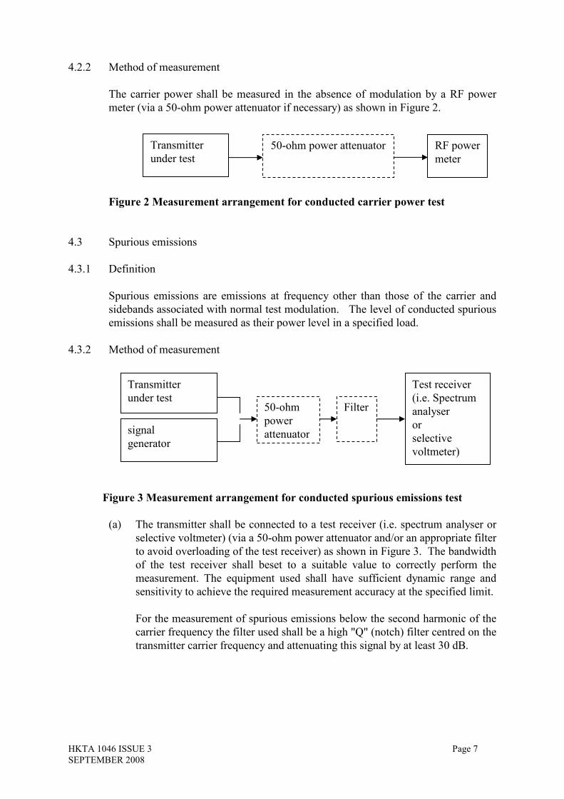
4.2.2 Method of measurement
The carrier power shall be measured in the absence of modulation by a RF power
meter (via a 50-ohm power attenuator if necessary) as shown in Figure 2.
Figure 2 Measurement arrangement for conducted carrier power test
4.3 Spurious emissions
4.3.1 Definition
Spurious emissions are emissions at frequency other than those of the carrier and
sidebands associated with normal test modulation. The level of conducted spurious
emissions shall be measured as their power level in a specified load.
4.3.2 Method of measurement
Figure 3 Measurement arrangem
(a) The transmitter shall be co
selective voltmeter) (via a 5
to avoid overloading of the
of the test receiver shall
measurement. The equipm
sensitivity to achieve the re
For the measurement of sp
carrier frequency the filter
transmitter carrier frequenc
Transmitter
under test
50-ohm power attenuator
RF power
meter
Transmitter
under test
signal
generator
Filter
Test receiver
(i.e. Spectrum
analyser
or
50-ohm
power
attenuator
Page 7
ent for conducted spurious emissions test
nnected to a test receiver (i.e. spectrum analyser or
0-ohm power attenuator and/or an appropriate filter
test receiver) as shown in Figure 3. The bandwidth
beset to a suitable value to correctly perform the
ent used shall have sufficient dynamic range and
quired measurement accuracy at the specified limit.
urious emissions below the second harmonic of the
used shall be a high "Q" (notch) filter centred on the
y and attenuating this signal by at least 30 dB.
selective
voltmeter)

HKTA 1046 ISSUE 3 Page 8
SEPTEMBER 2008
For the measurement of spurious emissions at and above the second harmonic
of the carrier frequency the filter used shall be a high pass filter with a stop
band rejection exceeding 40 dB. The cut-off frequency of the high pass filter
shall be approximately 1.5 times the transmitter carrier frequency.
Precautions may be required to ensure that the 50-ohm power attenuator does
not generate or that the high pass filter does not attenuate the harmonics of the
carrier.
(b) The transmitter shall be unmodulated and operating at the maximum limit of
its specified power range. Any spurious emission shall be detected by the test
receiver up to to 1 GHz or four times the working frequency whichever is the
greater, except for the channel on which the transmitter is intended to operate
and its adjacent channels.
(c) The frequency of the test receiver shall be adjusted over the specified
frequency range. The frequency and level of every spurious emission found
shall be noted.
The resolution bandwidth of the test receiver shall be the smallest bandwidth
available which is greater than the spectral width of the spurious component
being measured. This shall be considered to be achieved when the next highest
bandwidth causes less than 1 dB increase in amplitude. The conditions used in
the measurement shall be recorded in the test report.
(d) If the test receiver has not been calibrated in terms of power level at the
transmitter output, the level of any detected components shall be determined
by replacing the transmitter by the signal generator and adjusting it to
reproduce the frequency and level of every spurious emission recorded in
step (c).
(e) The absolute power level of each of the emissions noted shall be measured and
recorded.
(f) The measurement shall be repeated with the transmitter in stand-by condition
if this option is available.
HKTA 1046 ISSUE 3 Page 9
SEPTEMBER 2008
4.4 Frequency deviation
(This requirement applies only to the angle modulated transmitter intended primarily
for analogue speech)
The frequency deviation is the difference between the instantaneous frequency of the
modulated radio frequency signal and the carrier frequency in the absence of
modulation. The peak deviation is the largest value of the frequency deviation
during an audio frequency cycle. The frequency deviation shall be measured by
means of the deviation meter.
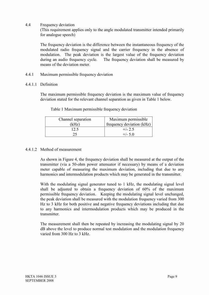
4.4.1 Maximum permissible frequency deviation
4.4.1.1 Definition
The maximum permissible frequency deviation is the maximum value of frequency
deviation stated for the relevant channel separation as given in Table 1 below.
Table 1 Maximum permissible frequency deviation
Channel separation
(kHz)
Maximum permissible
frequency deviation (kHz)
12.5
25
+/- 2.5
+/- 5.0
4.4.1.2 Method of measurement
As shown in Figure 4, the frequency deviation shall be measured at the output of the
transmitter (via a 50-ohm power attenuator if necessary) by means of a deviation
meter capable of measuring the maximum deviation, including that due to any
harmonics and intermodulation products which may be generated in the transmitter.
With the modulating signal generator tuned to 1 kHz, the modulating signal level
shall be adjusted to obtain a frequency deviation of 60% of the maximum
permissible frequency deviation. Keeping the modulating signal level unchanged,
the peak deviation shall be measured with the modulation frequency varied from 300
Hz to 3 kHz for both positive and negative frequency deviations including that due
to any harmonics and intermodulation products which may be produced in the
transmitter.
The measurement shall then be repeated by increasing the modulating signal by 20
dB above the level to produce normal test modulation and the modulation frequency
varied from 300 Hz to 3 kHz.

HKTA 1046 ISSUE 3 Page 10
SEPTEMBER 2008
4.4.2 Response of the transmitter to modulation frequencies above 3kHz
4.4.2.1 Definition
The frequency deviation characteristics of the transmitter at modulation frequencies
above 3 kHz are the peak deviation expressed as a function of modulation
frequencies above 3 kHz.
4.4.2.2 Method of measurement
As shown in Figure 4, the transmitter shall be connected to the deviation meter (via a
50 ohm power attenuator if necessary).
The transmitter shall be modulated by normal test modulation. Keeping the
modulating signal level unchanged, the modulation frequency shall be varied from 3
kHz to a frequency equal to the channel separation for which the equipment is
intended.
At each test frequency, the resulting frequency deviation shall be measured.
Figure 4 Measurement arrangement for conducted frequency deviation test
4.5 Adjacent channel power
(This requirement applies only to the angle modulated transmitter intended primarily
for analogue speech)
4.5.1 Definition
The adjacent channel power is that part of the total output power of a transmitter
under defined conditions of modulation, which falls within a specified passband
centred on the nominal frequency of either of the adjacent channels. This power is
the sum of the mean power produced by the modulation, hum and noise of the
transmitter.
It is specified either as the ratio expressed in decibels of the carrier power to the
adjacent channel power or as an absolute value.
Transmitter
under test
Modulating
signal generator
50-ohm power
attenuator
Deviation
meter
HKTA 1046 ISSUE 3 Page 11
SEPTEMBER 2008
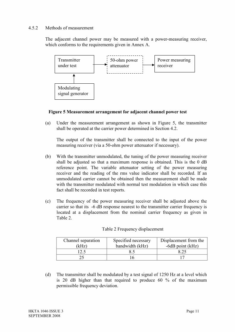
4.5.2 Methods of measurement
The adjacent channel power may be measured with a power-measuring receiver,
which conforms to the requirements given in Annex A.
Figure 5 Measurement arrangement for adjacent channel power test
(a) Under the measurement arrangement as shown in Figure 5, the transmitter
shall be operated at the carrier power determined in Section 4.2.
The output of the transmitter shall be connected to the input of the power
measuring receiver (via a 50-ohm power attenuator if necessary).
(b) With the transmitter unmodulated, the tuning of the power measuring receiver
shall be adjusted so that a maximum response is obtained. This is the 0 dB
reference point. The variable attenuator setting of the power measuring
receiver and the reading of the rms value indicator shall be recorded. If an
unmodulated carrier cannot be obtained then the measurement shall be made
with the transmitter modulated with normal test modulation in which case this
fact shall be recorded in test reports.
(c) The frequency of the power measuring receiver shall be adjusted above the
carrier so that its -6 dB response nearest to the transmitter carrier frequency is
located at a displacement from the nominal carrier frequency as given in
Table 2.
Table 2 Frequency displacement
Channel separation
(kHz)
Specified necessary
bandwidth (kHz)
Displacement from the
-6dB point (kHz)
12.5 8.5 8.25
25 16 17
(d) The transmitter shall be modulated by a test signal of 1250 Hz at a level which
is 20 dB higher than that required to produce 60 % of the maximum
permissible frequency deviation.
Transmitter
under test
Modulating
signal generator
50-ohm power
attenuator
Power measuring
receiver

HKTA 1046 ISSUE 3 Page 12
SEPTEMBER 2008
(e) The variable attenuator of the power measuring receiver shall be adjusted to
obtain the same reading as in step (b) or a known relation to it.
(f) The ratio of the adjacent channel power to the carrier power is the difference
between the attenuator settings in steps (b) and (e), corrected for any
differences in the reading of the rms value indicator. Alternatively, the
absolute value of the adjacent channel power may be calculated from the above
ratio and the carrier power.
(g) Step (c) to (f) shall be repeated with the power measuring receiver tuned to the
other side of the carrier.

HKTA 1046 ISSUE 3 Page 13
SEPTEMBER 2008
5. Methods of radiated measurements for transmitter parameters
For transmitters fitted with integral antennas, the methods of radiated measurement
specified in this Section apply.
When performing transmitter tests on equipment designed for intermittent operation,
the maximum transmit time specified by the manufacturer shall not be exceeded.
The test site and general arrangements for radiated measurements refer to Annex B.
Unless otherwise specified, the transmitter under test (TUT) shall be mounted on the
turntable, whose surface is at a convenient height within the quiet zone of the test
site. The phase centre of the test antenna and the mid-point of the TUT shall be
along the central line of the test site.
5.1 Frequency error
5.1.1 Definition
The frequency error of a transmitter is the difference between the measured carrier
frequency in the absence of modulation and the nominal frequency of the transmitter.
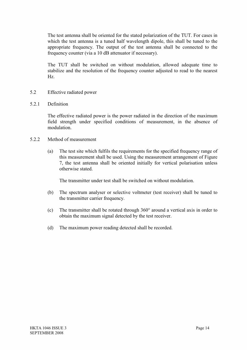
5.1.2 Method of measurement
Test Site
(1) the transmitter under test (TUT);
(2) Test antenna;
(3) Frequency Meter
Figure 6 Test Site set-up for the Frequency Error test
The TUT shall be mounted in an orientation which matches that of its normal usage
as stated by the manufacturer. The orientation and mounting configuration shall be
recorded.
1 2
3
HKTA 1046 ISSUE 3 Page 14
SEPTEMBER 2008
The test antenna shall be oriented for the stated polarization of the TUT. For cases in
which the test antenna is a tuned half wavelength dipole, this shall be tuned to the
appropriate frequency. The output of the test antenna shall be connected to the
frequency counter (via a 10 dB attenuator if necessary).
The TUT shall be switched on without modulation, allowed adequate time to
stabilize and the resolution of the frequency counter adjusted to read to the nearest
Hz.
5.2 Effective radiated power
5.2.1 Definition
The effective radiated power is the power radiated in the direction of the maximum
field strength under specified conditions of measurement, in the absence of
modulation.
5.2.2 Method of measurement
(a) The test site which fulfils the requirements for the specified frequency range of
this measurement shall be used. Using the measurement arrangement of Figure
7, the test antenna shall be oriented initially for vertical polarisation unless
otherwise stated.
The transmitter under test shall be switched on without modulation.
(b) The spectrum analyser or selective voltmeter (test receiver) shall be tuned to
the transmitter carrier frequency.
(c) The transmitter shall be rotated through 360° around a vertical axis in order to
obtain the maximum signal detected by the test receiver.
(d) The maximum power reading detected shall be recorded.

HKTA 1046 ISSUE 3 Page 15
SEPTEMBER 2008
Test Site
(1) Transmitter under test (TUT);
(2) Test antenna;
(3) Spectrum analyser or selective voltmeter (test receiver).
Figure 7 Test Site set-up for the Effective Radiated Power measurement on the TUT
(e) Using the measurement arrangement of Figure 8, the substitution antenna shall
replace the TUT in the same position and in vertical polarisation. The
frequency of the signal generator shall be adjusted to the transmitter carrier
frequency.
(f) The input signal to the substitution antenna shall be adjusted in level until an
equal or a known related level to that detected from the transmitter is obtained
in the test receiver.
(g) The effective radiated power is equal to the power supplied by the signal
generator, increased by the known relationship if necessary and after
corrections due to the gain of the substitution antenna and the cable loss
between the signal generator and the substitution antenna.
(h) Steps (b) to (g) above shall be repeated with the test antenna and the
substitution antenna oriented in horizontal polarisation.
Test Site
(1) Signal generator;
(2) Substitution antenna;
(3) Test antenna;
(4) Spectrum analyser or selective voltmeter (test receiver).
Figure 8 Substitution antenna replacing the TUT
1 2
3
1
2 3
4

HKTA 1046 ISSUE 3 Page 16
SEPTEMBER 2008
5.3 Radiated spurious emissions
5.3.1 Definition
Spurious emissions are emissions at frequencies other than those of the carrier and
sidebands associated with normal modulation, radiated by the antenna and by the
cabinet of the transmitter.
They are specified as the radiated power of any discrete signal.
5.3.2 Method of measurement
Test Site
(1) Transmitter under test (TUT);
(2) Test antenna;
(3) High 'Q' (notch) or high pass filter;
(4) Spectrum analyser or selective voltmeter (test receiver).
Figure 9 Test Site set-up for Spurious Emissions testing
(a) The test site, which fulfils the requirements of the specified frequency range of
this measurement, shall be used.
Using the measurement arrangement of Figure 9, the test antenna shall be
oriented initially for vertical polarisation and connected to a spectrum analyser
or a selective voltmeter (test receiver), through a suitable filter to avoid
overloading. The bandwidth of the test receiver shall be set to a suitable value
to correctly perform the measurement.
For the measurement of spurious emissions below the second harmonic of the
carrier frequency the filter used shall be a high 'Q' (notch) filter centred on the
transmitter carrier frequency and attenuating this signal by at least 30 dB.
For the measurement of spurious emissions at and above the second harmonic
of the carrier frequency the filter used shall be a high pass filter with a stop
band rejection exceeding 40 dB. The cut-off frequency of the high pass filter
shall be approximately 1.5 times the transmitter carrier frequency.
The transmitter under test shall be switched on without modulation.
1 2
3 4

HKTA 1046 ISSUE 3 Page 17
SEPTEMBER 2008
(b) The radiation of any spurious emission shall be detected by the test antenna
and test receiver up to to 1 GHz or four times the working frequency
whichever is the greater, except for the channel on which the transmitter is
intended to operate and its adjacent channels. The frequency of each spurious
emission detected shall be recorded.
(c) At each frequency at which an emission has been detected, the test receiver
shall be tuned.
(d) The transmitter shall be rotated through 360° about a vertical axis, until a
maximum signal is received.
(e) The reading of the maximum signal shown in the test receiver shall be
recorded.
The resolution bandwidth of the test receiver shall be the smallest bandwidth
available which is greater than the spectral width of the spurious component
being measured. This shall be considered to be achieved when the next highest
bandwidth causes less than 1 dB increase in amplitude. The conditions used in
the measurement shall be recorded in the test report.
(f ) Using the measurement arrangement of Figure 10, the substitution antenna
shall replace the TUT in the same position and in vertical polarisation. The
substitution antenna shall be connected to the signal generator.
Test Site
(1) Signal generator;
(2) Substitution antenna;
(3) Test antenna;
(4) High 'Q' (notch) or high pass filter;
(5) Spectrum analyser or selective voltmeter (test receiver).
Figure 10 Substitution antenna replacing TUT for Spurious Emission testing
(g) At each frequency at which an emission has been detected, the signal
generator, substitution antenna and test receiver shall be correspondingly
tuned.
4
3 2
1 5
HKTA 1046 ISSUE 3 Page 18
SEPTEMBER 2008
(h) The level of the signal generator giving the same signal level on the test
receiver as in item (e) above shall be recorded. This value, after corrections
due to the gain of the substitution antenna and the cable loss between the
signal generator and the substitution antenna, is the radiated spurious emission
at this frequency.
(i) Steps (c) to (h) above shall be repeated with the test antenna oriented in
horizontal polarisation.
(j) Steps (c) to (i) above shall be repeated with the transmitter in stand-by
condition if this option is available.
5.4 Frequency deviation
(This requirement applies only to the angle modulated transmitter intended primarily
for analogue speech)
The frequency deviation is the difference between the instantaneous frequency of the
modulated radio frequency signal and the carrier frequency in the absence of
modulation. The peak deviation is the largest value of the frequency deviation
during an audio frequency cycle. Only the maximum value of the peak frequency
deviation available in the transmitter will be measured. The frequency deviation
shall be measured by means of the deviation meter.
5.4.1 Maximum permissible frequency deviation
5.4.1.1 Definition
The maximum permissible frequency deviation is the maximum value of frequency
deviation stated for the relevant channel separation as specified in Table 1.
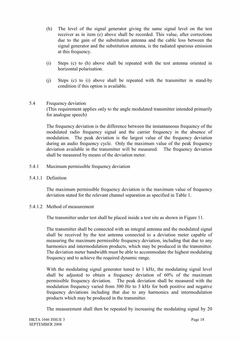
5.4.1.2 Method of measurement
The transmitter under test shall be placed inside a test site as shown in Figure 11.
The transmitter shall be connected with an integral antenna and the modulated signal
shall be received by the test antenna connected to a deviation meter capable of
measuring the maximum permissible frequency deviation, including that due to any
harmonics and intermodulation products, which may be produced in the transmitter.
The deviation meter bandwidth must be able to accommodate the highest modulating
frequency and to achieve the required dynamic range.
With the modulating signal generator tuned to 1 kHz, the modulating signal level
shall be adjusted to obtain a frequency deviation of 60% of the maximum
permissible frequency deviation. The peak deviation shall be measured with the
modulation frequency varied from 300 Hz to 3 kHz for both positive and negative
frequency deviations including that due to any harmonics and intermodulation
products which may be produced in the transmitter.
The measurement shall then be repeated by increasing the modulating signal by 20

HKTA 1046 ISSUE 3 Page 19
SEPTEMBER 2008
dB above the level to produce normal test modulation and the modulation frequency
varied from 300 Hz to 3 kHz.
The value of the frequency deviation on the deviation meter shall be recorded in the
test report.
Test Site
(1) Modulating signal generator
(2) the transmitter under test with an integral antenna;
(3) Test antenna;
(4) Deviation Meter
Figure 11 Test Site set-up for the Frequency Deviation test
5.4.2 Response of the transmitter to analogue signals above the audio bandwidth (above 3
kHz)
5.4.2.1 Definition
The frequency deviation characteristics of the transmitter at modulation frequencies
above 3 kHz is the peak deviation expressed as a function of modulation frequencies
above 3 kHz.
5.4.2.2 Method of measurement
The transmitter under test shall be placed inside a test site as shown in Figure 11.
The transmitter shall be connected with an integral antenna and the modulated signal
shall be received by the test antenna connected to the deviation meter.
The transmitter shall be modulated by normal test modulation. Keeping the
modulating signal level unchanged, the modulation frequency shall be varied from 3
kHz equal to a frequency equal to the channel separation for which the equipment is
intended.
At each test frequency, the resulting frequency deviation shall be measured.
1
2 3
4

HKTA 1046 ISSUE 3 Page 20
SEPTEMBER 2008
5.5 Adjacent channel power
(This requirement applies only to the angle modulated transmitter intended primarily
for analogue speech)
5.5.1 Definition
The adjacent channel power is that part of the total power output of a transmitter
under defined conditions of modulation, which falls within a specified passband
centred on the nominal frequency of either of the adjacent channels. This power is
the sum of the mean power produced by the modulation, hum and noise of the
transmitter.
It is specified either as the ratio expressed in decibels of the effective radiated power
to the adjacent channel power or as an absolute value.
5.5.2 Method of measurement
The adjacent channel power may be measured with a power measuring receiver,
which conforms to the requirements given in Annex A.
Test Site
(1) Modulating signal generator;
(2) Transmitter under test (TUT);
(3) Test antenna;
(4) Power measuring receiver
Figure 12 Test Site set-up for Adjacent Channel Power test
(a) A test site, which fulfils the requirements of the specified frequency range of
this measurement, shall be used. Using the measurement arrangement of
Figure 12, the transmitter under test shall be placed inside the test site and
connected with a modulating signal generator. The test antenna shall be
oriented initially for vertical polarisation and connected to a power measuring
receiver calibrated to measure rms power level. The level at the input of the
power measuring receiver shall be within its allowed limit. The transmitter
shall be operated at the effective radiated power determined in Section 5.2.
2 3
4 1
HKTA 1046 ISSUE 3 Page 21
SEPTEMBER 2008
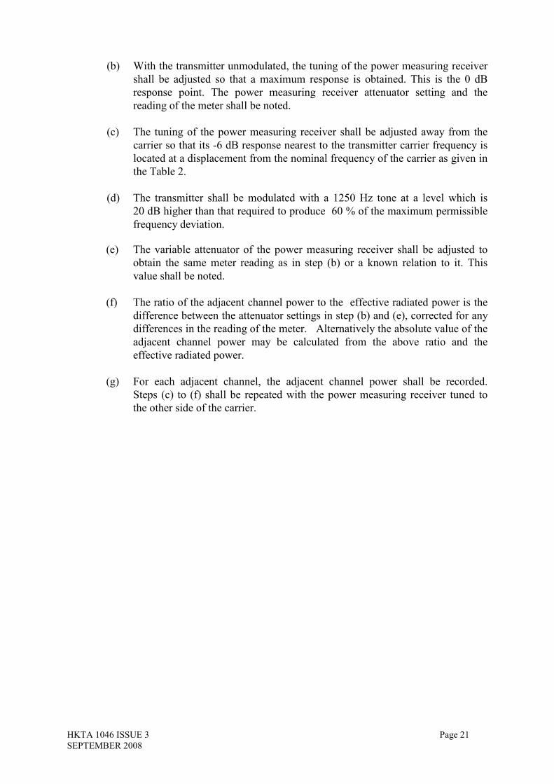
(b) With the transmitter unmodulated, the tuning of the power measuring receiver
shall be adjusted so that a maximum response is obtained. This is the 0 dB
response point. The power measuring receiver attenuator setting and the
reading of the meter shall be noted.
(c) The tuning of the power measuring receiver shall be adjusted away from the
carrier so that its -6 dB response nearest to the transmitter carrier frequency is
located at a displacement from the nominal frequency of the carrier as given in
the Table 2.
(d) The transmitter shall be modulated with a 1250 Hz tone at a level which is
20 dB higher than that required to produce 60 % of the maximum permissible
frequency deviation.
(e) The variable attenuator of the power measuring receiver shall be adjusted to
obtain the same meter reading as in step (b) or a known relation to it. This
value shall be noted.
(f) The ratio of the adjacent channel power to the effective radiated power is the
difference between the attenuator settings in step (b) and (e), corrected for any
differences in the reading of the meter. Alternatively the absolute value of the
adjacent channel power may be calculated from the above ratio and the
effective radiated power.
(g) For each adjacent channel, the adjacent channel power shall be recorded.
Steps (c) to (f) shall be repeated with the power measuring receiver tuned to
the other side of the carrier.

HKTA 1046 ISSUE 3 Page 22
SEPTEMBER 2008
6. Measurement uncertainty
The maximum allowable measurement uncertainties based on a level of confidence
of 95% for all tests are stated below:
Valid up to 1 GHz for the RF parameters unless otherwise stated.
RF frequency 1 x 10⁻⁶
Carrier power (Conducted) 4 dB
Radiated RF power 6 dB
Frequency deviation 5 %
Adjacent channel power 5 dB
Conducted emission of transmitter, valid to 4 GHz 4 dB
Radiated emission of transmitter, valid to 4 GHz 6 dB
For each test, the 95% confidence level measurement uncertainty of the measured
result should be evaluated and stated in the test report together with the
corresponding coverage factor.

HKTA 1046 ISSUE 3 Page 23
SEPTEMBER 2008
7. Reference
[1] HKTA 1002 “Performance Specification for Angle Modulated Radio
Transmitters and Receivers for use as Base, Mobile and Portable Equipment
for Land Mobile Radio Service”
[2] ETSI EN 300 086-1 “Electromagnetic compatibility and Radio spectrum
Matters (ERM); Land Mobile Service; Radio equipment with an internal and
external RF connector intended primarily for analogue speech; Part 1
Technical characteristics and methods of measurement”
[3] ETSI EN 300 296-1 “Electromagnetic compatibility and Radio spectrum
Matters (ERM); Land Mobile Service; Radio equipment using internal
antennas intended primarily for analogue speech; Part 1 Technical
characteristics and methods of measurement”
[4] “Guide to the Expression of Uncertainty in Measurement” published by BIPM,
IEC, IFCC, ISO, IUPAC, IUPAP and OIML

HKTA 1046 ISSUE 3
SEPTEMBER 2008
Annex A (normative): Specifications for adjacent channel power
measurement arrangements
{The following general arrangements are extracted from Annex B – Specifications for
adjacent channel power measurement arrangements of ETSI EN 300 086-1}
A.1 Power measuring receiver specification
The power measuring receiver consists of a mixer, an IF filter, and oscillator, an
amplifier, a variable attenuator and an rms value indicator. Instead of the variable
attenuator with the rms value indicator it is also possible to use an rms voltmeter
calibrated in dB as the rms value indicator. The technical characteristics of the
power-measuring receiver are given in Sections A.1.1 to A.1.4.
A.1.1 IF filter
The IF filter shall be within the limits of the following selectivity characteristic.
F
Distant fr
carrier
Close to
carrier
P
igure A.1 Limits of the selectivity characteristic
om
age 24

HKTA 1046 ISSUE 3 Page 25
SEPTEMBER 2008
Depending on the channel separation, the selectivity characteristic shall keep the
following separations from the nominal centre frequency of the adjacent channel:
Table A.1 Selectivity characteristic
Channel
separation
Frequency separation of filter curve from nominal centre frequency of adjacent
channel (kHz)
(kHz) D1 D2 D3 D4
12.5 3 4.25 5.5 9.5
25 5 8.0 9.25 13.25
Depending on the channel separation, the attenuation points shall not exceed the
tolerances given in Table A.2 and Table A.3.
Table A.2 Attenuation points close to carrier
Channel
separation
Tolerance range (kHz)
(kHz) D1 D2 D3 D4
12.5 +1.35 +0.1 -1.35 -5.35
25 +3.1 +0.1 -1.35 -5.35
Table A.3 Attenuation points distant from the carrier
Channel
separation
Tolerance range (kHz)
(kHz) D1 D2 D3 D4
12.5 +2.0 +2.0 +2.0 +2.0
-6.0
25 +3.5 +3.5 +3.5 +3.5
-7.5
The minimum attenuation of the filter outside of 90dB attenuation points shall be
equal to or greater than 90dB.
Table A.4 Frequency displacement
Channel
separation (kHz)
Specified necessary
Bandwidth (kHz)
Displacement from the
-6 dB point (kHz)
12.5
8.5 8.25
25
16 17
The tuning of the power-measuring receiver shall be adjusted away from the carrier
so that the -6 dB response nearest to the transmitter carrier frequency is located at a
displacement from the nominal carrier frequency as given in Table A.4.

HKTA 1046 ISSUE 3 Page 26
SEPTEMBER 2008
A.1.2 Variable attenuator
The variable attenuator shall have a minimum range of 80 dB and a resolution of
1 dB.
A.1.3 Rms value indicator
The instrument shall accurately indicate non-sinusoidal signals in a ratio of up to
10:1 between peak value and rms value.
A.1.4 Oscillator and amplifier
The oscillator and the amplifier shall be designed in such a way that the
measurement of the adjacent channel power of a low-noise unmodulated transmitter,
whose self-noise has a negligible influence on the measurement result, yields a
measurement result, yields a measured value of ≤ -90dB for channel separations of
25kHz and of ≤ -80dB for a channel separation of 12.5kHz, referred to the carrier of
the oscillator.
HKTA 1046 ISSUE 3 Page 27
SEPTEMBER 2008
Annex B(normative): Radiated measurements
{The following general arrangements are extracted from Annex A
– Radiation measurement of ETSI EN 300 086-1} B.1 Test site and general arrangements for measurements involving the use of
radiated fields
To ensure reproducibility and traceability of radiated measurements, free field test
site shall be used for conducting the tests. Both absolute and relative measurements
can be performed in a test site. Where absolute measurements are to be carried out,
the chamber shall be verified.
B.1.1 Test Sites
B.1.1.1 Anechoic Chamber
An Anechoic Chamber is an enclosure, usually shielded, whose internal walls, floor
and ceiling are covered with radio absorbing material, normally of the pyramidal
urethane foam type. The chamber usually contains an antenna support at one end and
a turntable at the other.
The chamber shielding and radio absorbing material work together to provide a
controlled environment for testing purposes. This type of test chamber attempts to
simulate free space conditions.
B.1.1.2 Anechoic Chamber with a conductive ground plane
An anechoic chamber with a conductive ground plane is an enclosure, usually
shielded, whose internal walls and ceiling are covered with radio absorbing material,
normally of the pyramidal urethane foam type. The floor, which is metallic, is not
covered and forms the ground plane. The chamber usually contains an antenna mast
at one end and a turntable at the other. This type of test chamber attempts to
simulate an ideal open test site whose primary characteristics is a perfectly
conducting ground plane of infinite extent.
B.1.1.3 Open Area Test Site
An open area test site comprises a turntable at one end and an antenna mast of
variable length at the other end above a ground plane which, in the ideal case, is
perfectly conducting and of infinite extent. In practice, whilst good conductivity can
be achieved, the ground plane size has to be limited.
B.1.2 Test antenna
A test antenna is always used in radiated test methods. In emission tests the test
antenna is used to detect the field from the EUT in one stage of the measurement and
from the substitution antenna in the other stage.

HKTA 1046 ISSUE 3 Page 28
SEPTEMBER 2008
The test antenna should be mounted on a support capable of allowing the antenna to
be used in either horizontal or vertical polarization.
In the frequency band 30 MHz to 1000 MHz, dipole antennas (constructed in
accordance with ANSI C63.5) are generally recommended. For frequencies of 80
MHz and above, the dipoles should have their arm lengths set for resonance at the
frequency of test. Below 80 MHz, shortened arm lengths are recommended. For
spurious emission testing, however, a combination of bicones and log periodic
dipole array antennas (commonly termed 'log periodics') could be used to cover the
entire 30 MHz to 1 000 MHz band. Above 1 000 MHz, waveguide horns are
recommended although, again, log periodics could be used.
B.1.3 Substitution antenna
The substitution antenna is used to replace the EUT for tests in which a transmitting
parameter is being measured. For measurements in the frequency band 30 MHz to
1000 MHz, the substitution antenna should be a dipole antenna (constructed in
accordance with ANSI C63.5). For frequencies of 80 MHz and above, the dipoles
should have their arm lengths set for resonance at the frequency of test. Below 80
MHz, shortened arm lengths are recommended. For measurements above 1000 MHz,
a waveguide horn is recommended. The centre of this antenna should coincide with
either the phase centre or volume centre.
B.2 Guidance on the use of radiation test sites
This Section details procedures, test equipment arrangements and verification that
shall be carried out before any of the radiated tests are undertaken.
B.2.1 Verification of the test site
No test shall be carried out on a test site, which does not possess a valid verification.
B.2.2 Preparation of the EUT
The manufacturer shall supply information about the EUT covering the operating
frequency, polarization, supply voltage(s) and the reference face. Additional
information, specific to the type of EUT shall include, where relevant, carrier power,
channel separation, whether different operating modes are available (e.g. high and
low power modes) and if operation is continuous or is subject to a maximum test
duty cycle (e.g. 1 minute on, 4 minutes off).
Where necessary, a mounting bracket of minimal size shall be available for
mounting the EUT on the turntable. This bracket shall be made from low
conductivity, low relative dielectric constant (i.e. less than 1.5) material(s) such as
expanded polystyrene, balsawood, etc.
HKTA 1046 ISSUE 3 Page 29
SEPTEMBER 2008
B.2.3 Power supplies to the EUT
All tests shall be performed using power supplies wherever possible, including tests
on EUT designed for battery-only use. In all cases, power leads shall be connected to
the EUT's supply terminals (and monitored with a digital voltmeter) but the battery
shall remain present, electrically isolated from the rest of the equipment, possibly by
putting tape over its contacts.
The presence of these power cables can, however, affect the measured performance
of the EUT. For this reason, they shall be made to be "transparent" as far as the
testing is concerned. This can be achieved by routing them away from the EUT and
down to either the screen, ground plane or facility wall (as appropriate) by the
shortest possible paths. Precautions shall be taken to minimize pick-up on these
leads (e.g. the leads could be twisted together, loaded with ferrite beads at 0.15 m
spacing or otherwise loaded).
B.2.4 Range length
The range length for the test site shall be adequate to allow for testing in the far field
of the EUT i.e. it shall be equal to or exceed:
2(d1 + d2)2
λ
where:
d1 is the largest dimension of the EUT/dipole after substitution (m);
d2 is the largest dimension of the test antenna (m);
λ is the test frequency wavelength (m).
It shall be noted that in the substitution part of this measurement, where both test and
substitution antennas are half wavelength dipoles, this minimum range length for far-
field testing would be:
2λ
It shall be noted in test reports when either of these conditions is not met so that the
additional measurement uncertainty can be incorporated into the results.
B.2.5 Site preparation
The cables for both ends of the anechoic chamber should be routed horizontally
away from the testing area and then allowed to drop vertically and out through either
the ground plane or screen (as appropriate) to the test equipment. Precautions should
be taken to minimize pick up on these leads (e.g. dressing with ferrite beads, or other
loading). The cables, their routing and dressing should be identical to the verification
set-up.
Calibration data for all items of test equipment shall be available and valid. For test
and substitution antennas, the data shall include gain relative to an isotropic radiator
(or antenna factor) for the frequency of test.

HKTA 1046 ISSUE 3 Page 30
SEPTEMBER 2008
The calibration data on all cables and attenuators shall include insertion loss
throughout the entire frequency range of the tests. All insertion loss figures shall be
recorded for the specific test.
Where correction factors/tables are required, these shall be immediately available.
- End -