method of test for curing, capping and determining the … · 2019-11-20 · cylindrical concrete...
TRANSCRIPT
DOTD TR 230 Rev 09/10/19 Page 1 of 13
Method of Test for
CURING, CAPPING AND DETERMINING THE COMPRESSIVE STRENGTH OF CYLINDRICAL CONCRETE SPECIMENS
DOTD Designation: TR 230
I. Scope This method describes the procedure for curing, capping and determining the compressive strength of cylindrical concrete specimens such as molded cylinders and drilled cores.
II. Reference Documents A. DOTD TR 226 – Making, Field Curing and Transporting Concrete Test Specimens B. DOTD TR 227 – Making and Curing Compressive Strength Specimens for Concrete Pipe C. AASHTO T 22 – Compressive Strength of Cylindrical Concrete Specimens D. ASTM C39 – Compressive Strength of Cylindrical Concrete Specimens E. AASHTO T 231 – Capping Cylindrical Concrete Specimens F. AASHTO M 201 – Moist Cabinets, Moist Rooms, and Water Storage Tanks Used in the
Testing of Hydraulic Cements and Concretes G. ASTM C1231 – Use of Unbonded Caps in Determination of Compressive Strength of
Hardened Cylindrical Concrete Specimens
III. Apparatus A. Moist Room – Shall conform to AASHTO M 201. The use of relative humidity recording
devices is optional. When automatic relative humidity recording devices are not used, the relative humidity shall be measured and recorded weekly.
B. Water Storage Containers – Shall conform to AASHTO M 201. C. Suitable Absorbent Fabric – A fabric, such as burlap, having the capability of holding
moisture for a suitable period of time. D. Sling Psychrometer or Hygrometer – For determining the relative humidity in moist rooms
not equipped with a relative humidity recording device and for the periodic measurement and verification of relative humidity.
E. Capping Equipment 1. For use with neoprene caps:
a. Two Steel Retaining Rings – Conforming to ASTM C1231. b. Miscellaneous – Safety glasses or goggles, gloves, absorbent paper towels or cloth.
2. For use with sulfur mortar caps: a. Alignment Devices, Capping Plates, and Melting Pots – Conforming to AASHTO T
231. b. Power Vented Hood – To exhaust fumes to outdoors. c. Small Tools – Feeler gage, readable to 0.02 inches, large metal ladle and a
straightedge. d. Thermometer – Dial or digital thermometer with a metal stem and a minimum range
of 50°F to 400°F and sensitive to 2°F. e. Miscellaneous – Safety glasses or goggles, gloves, mineral oil, application brush and
absorbent paper towels or cloths. F. Capping Material
DOTD TR 230 Rev 09/10/19 Page 2 of 13
1. Neoprene Caps – Conforming to ASTM C1231. 2. Sulfur Mortar Caps – Conforming to AASHTO T 231, except the minimum
compressive strength of the mortar shall be 6,000 psi in 2 hours. G. Testing Machine – Including upper and lower bearing blocks, shall conform to AASHTO
T 22. Each cylinder testing machine shall be equipped with a protective cage. The testing machine shall be calibrated at least every 6 months for machines used for both acceptance and independent assurance samples and at least every 12 months for machines used for acceptance testing only.
H. Measuring Device – Caliper or micrometer readable to the nearest 0.01 inches and capable of measuring the diameter of the concrete cylinders at mid-height.
I. Waterproof Black Ink Marker. J. Mold Removal Device – Capable of removing plastic molds without damaging the concrete
cylinders. K. Small Tools – Combination square, depth gage and steel ruler both readable to 0.0625
inches. These tools are needed to check ends of each cylinder prior to and after capping. L. Metal File, Grinder and Concrete Saw – For planing the ends of concrete cylinders before
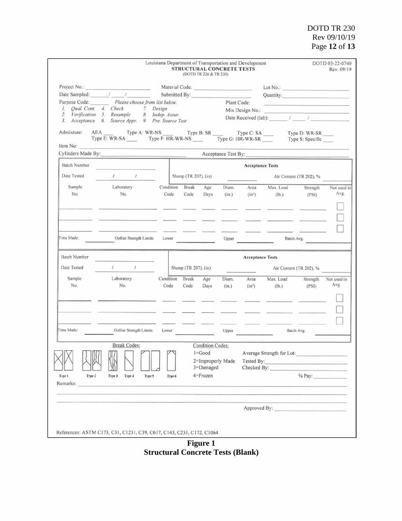
testing. M. Worksheet – Structural Concrete Tests, DOTD Form No. 03-22-0740 (Figure 1/Figure 2). N. Numbered Field Book – For recording precast cylinder identification and test data.
IV. Health Precautions
Proper ventilation is required when using sulfur mortar capping compounds due to the potentially hazardous fumes that could develop during heating. Capping compounds are hot molten liquids and can splatter and burn. Proper hand, arm, eye, face and footwear protection shall be used when working with capping compounds. Caution should be exercised when testing all concrete cylinders, especially when using neoprene caps. Cylinders tested with neoprene caps are subject to shatter more intensely than cylinders tested with sulfur mortar caps. The protective cage on each testing machine shall be used during testing.
V. Sample Cylinders shall be molded to have a diameter of 6 inches and a nominal height of 12 inches or shall be molded to have a diameter of 4 inches and a nominal height of 8 inches. Field cure and transport the cylinders in accordance with TR 226 or TR 227.
VI. Procedure
A. Specimen Preparation 1. As soon as the cylinders are delivered to the laboratory, the PE office technician or
contractor’s representative shall scan the SMM bar code accompanying the cylinders and verify information marked on the side of the mold or top of each cylinder with the information entered on the worksheet or in the field book.
2. Remove the rubber band and polyethylene bag or plastic cap from each cylinder. 3. Transfer identifying information from the side of the mold to the top of the concrete
cylinder before removing the mold. 4. Carefully remove the mold from each cylinder with the mold removal device without
damaging the cylinder.
DOTD TR 230 Rev 09/10/19 Page 3 of 13
5. Examine and check each cylinder conditions. Damaged or improperly made cylinders
shall not be tested. 6. Identify each cylinder in the following manner.
a. Write the laboratory number or sample number on the side of the cylinder with the black ink marker.
b. Inspectors shall deliver the cylinders to the lab with the SMM labels unattached and place the labels underneath the cylinders. A District or Materials Lab employee shall then scan samples into the system. Labels are available for printing on the LA DOTD internet page.
7. Cure in the following manner: a. Cast-in-place concrete for form removal and acceptance: cure within 30 minutes after
removing the molds and store specimens in a moist room or storage container until the time of testing, except for early break cylinders that are to be capped and tested immediately.
b. Precast concrete for form removal and acceptance: provide each cylinder with the same temperature and moisture environment as the structural member until time of test.
B. Determining the Cross-Sectional Area Prior to Capping 1. Verify the information written on the top and side of each cylinder with the information
entered on the worksheet or field book. 2. Visually inspect each cylinder for damage. Damaged cylinders having projections or
depressions on the ends greater than 1/8 inch, out of round, out of plane or honey combed, etc. shall not be tested unless projections are corrected.
3. Concrete cylinders shall not be tested if any individual diameter of a cylinder differs from any other diameter of the same cylinder by more than 2 percent (+/- 0.12 inches for a 6-inch diameter cylinder and/or +/- 0.08 inches for a 4-inch diameter cylinder). Deformations may occur during molding or when the single use molds are damaged or deformed during transportation.
4. The diameter used for calculating the cross-sectional area of the specimen shall be determined to the nearest 0.01 in. by averaging two diameters measured at right angles to each other at about mid-height of the specimen.
Note 1: See Section VII for sample calculations. C. Capping Cylindrical Concrete Specimens
1. Capping cylinders using unbonded neoprene caps (ASTM C1231) a. Wipe the ends of the cylinders dry so that no free water or foreign matter remains on
areas to be capped. b. When the retaining rings containing neoprene caps are in place, neither end of the
compression test cylinder shall depart from perpendicular to the axis by more than 0.5°.
c. When using unbonded neoprene caps, verify the alignment of the specimen after application of load, but before reaching 10% of the anticipated specimen strength. Check to see that the axis of the cylinder does not depart from vertical by more than 0.5° and that the ends of the cylinder are centered within the retaining rings. If the cylinder alignment does not meet these requirements, release the load, and carefully recenter the specimen. Reapply load and recheck specimen centering and alignment.

DOTD TR 230 Rev 09/10/19 Page 4 of 13
d. The ends of compressive test specimens that are not plane within 0.002 inches shall
be sawed or ground to meet the tolerance or capped in accordance with either AASHTO T231 or, when permitted, ASTM C1231.
e. Cylinders not meeting these tolerances for perpendicularity and planeness shall not be tested unless the irregularity is corrected.
2. Capping cylinders with sulfur mortar (AASHTO T 231) a. Wipe the ends of the cylinders dry so that no free water or foreign matter remains on
areas to be capped. b. Moist-cured cylinders shall be maintained in a moist condition between the
completion of capping and the time of testing by returning them to moist storage or covering them with suitable moist absorbent fabric.
c. For sulfur mortar, immediately cap the ends of the sulfur mortar in accordance with AASHTO T 231. Sulfur mortar caps shall cure at least 2 hours prior to testing.
d. Use alignment devices with capping plates to ensure that no single cap will depart from perpendicular to the axis by more than 0.5° (approximately equivalent to 0.12 inches in 12 inches for a 6-by-12-inch cylinder or 0.08 inches in 8 inches for a 4-by-8-inch cylinder). If the capped cylinder appears to deviate from this tolerance, place the cylinder on a level surface and measure the angle of deviation by use of a combination square and steel ruler. Cylinders not meeting this tolerance shall not be tested unless the irregularity is first corrected.
e. The surface of capped compression cylinders shall be plane with a tolerance of 0.002 inches across any diameter. During each day’s capping operation, planeness of the caps on at least three cylinders representing the start, middle, and end of the run, shall be checked by means of a straightedge and feeler gage, making a minimum of three measurements on different diameters to ensure that the surfaces of the caps do not depart from a plane by more than 0.002 inches.
f. For a cylinder compressive strength of 500-7,000 psi, the average cap thickness should be about 0.25 inches, and in no instance shall any part of a cap be thicker than 0.31 inches. For a cylinder compressive strength greater than 7,000 psi, the average cap thickness should be about 0.125 inches, and in no instance shall any part of a cap be more than 0.20 inches thick.
D. Determining compressive strength of cylindrical specimens 1. Determine compressive strength of cylinders using unbonded neoprene caps
Note 2: Tolerances for specimen ages when determining compressive strength are as follows: Test Age Permissible Tolerance 24 hours +/-0.5 hours 3 days +/- 2 hours 7 days +/- 6 hours 28 days - 20 hours to +3 days 56 days +/- 2 days 90 days +/- 2 days
a. Do not use neoprene caps for acceptance testing of concrete with compressive strength below 1,500 psi or above 12,000 psi. The Shore A Durometer Hardness shall be 50 for concrete strengths between 1,500 and 6,000 psi. The Shore A Durometer Hardness shall be 60 for concrete strengths between 2,500 and 7,000 psi.

DOTD TR 230 Rev 09/10/19 Page 5 of 13
The Shore A Durometer Hardness shall be 70 for concrete strengths between 4,000 and 7,000 psi. For the prestressed or unusual applications where specified concrete strength will exceed 7,000 psi, a Shore A Durometer Hardness of 70 will be required.
b. The same surface of the neoprene cap shall bear on the concrete cylinder for all tests performed with that cap.
c. Examine each neoprene cap for excessive wear or damage. Replace neoprene caps that have cracks or splits exceeding 3/8 inches in length regardless of depth. Insert the neoprene caps in the steel retaining rings before they are placed on the cylinder.
d. Wipe the ends of the cylinder and the bearing face of each steel retaining ring with an absorbent paper towel or cloth to remove any foreign matter.
e. Place the steel retaining rings, containing the neoprene caps, on the top and bottom surface of each concrete cylinder. No loose particles shall be trapped between the concrete cylinder and neoprene caps.
f. Visually inspect the cylinder to determine if the neoprene cap system is properly seated, centered on the cylinder, and the axis of the cylinder with cap is perpendicular as stated in step VI.C.1.b. If the cylinder appears out of tolerance, measure the angle of deviation by use of the combination square and steel ruler. Cylinders not meeting the tolerance allowed shall not be tested unless this irregularity is first corrected.
g. Wipe clean the bearing faces of the upper and lower bearing blocks of the testing machine. Place the test cylinder on the lower bearing block and carefully align the axis of the cylinder with the center thrust of the spherically seated block.
h. Rotate the spherically seated block immediately prior to testing to assure freedom of movement. The blocks shall be designed to be rotated freely and tilted at least 4° in any direction.
i. Do not use a neoprene cap to test more than 100 cylinders. j. Do not use a neoprene cap to test more than 50 cylinders for concrete strength
exceeding 7,000 psi. 2. Determining compressive strength of cylinders using sulfur-mortar caps
a. Prior to positioning the cylinders in the machine, wipe the bearing faces of both blocks and the ends of the cylinders to remove any foreign matter which might interfere with testing operations.
b. Place the test cylinder on the lower bearing block and carefully align the axis of the cylinder with the center thrust of the spherically seated block.
c. Rotate the spherically seated block immediately prior to testing to assure freedom of movement. The blocks shall be designed to be rotated freely and tilted at least 4° in any direction.
E. Loading 1. Apply the load continuously and without shock. 2. Moist cured cylinders must be kept in a moist condition prior to testing. Cylinders may
be kept outside of the moist room for up to three (3) hours prior to testing by covering the cylinders with a moist absorbent fabric in an environment between 68 to 86°F.
3. Apply the load at a rate of movement corresponding to a stress rate on the specimen of 35 ± 7 psi/s.
4. During the application of the first half of the anticipated loading phase a higher rate of loading is permitted.

DOTD TR 230 Rev 09/10/19 Page 6 of 13
5. The designed rate of movement shall be maintained at least during the latter half of the
anticipated loading phase. 6. When loads are indicated on a digital readout machine, the cylinder is considered to be
in failure when the load is decreasing steadily and the specimen displays a well-defined fracture pattern.
7. When testing with unbound caps, a corner fracture similar to Type 5 or Type 6 may occur as shown in Figure 1/Figure 2 before the ultimate capacity of the specimen has been obtained. Continue compressing the specimen until the ultimate capacity of the specimen has been obtained.
8. Cylinders shall be loaded to failure and the break type recorded as classified in Figure 1 and Figure 2.
9. Should it become apparent during loading operations that the capping compound used is breaking before the cylinder reaches failure, it should be assumed that the cap is defective. The loading procedure shall then be discontinued and the cylinder removed and recapped in accordance with step VI.C.2.c. The load shall again be applied until failure is reached.
VII. Calculations
A. Determination of average diameter (D): Example: Diameter 1 (in.) = 6.03 inches Diameter 2 (in.) = 6.03 inches
𝐴𝐴𝐴𝐴𝐴𝐴𝐴𝐴𝐴𝐴𝐴𝐴𝐴𝐴 𝐷𝐷𝐷𝐷𝐴𝐴𝐷𝐷𝐴𝐴𝐷𝐷𝐴𝐴𝐴𝐴 (𝐷𝐷) = �𝐷𝐷𝐷𝐷𝐴𝐴𝐷𝐷𝐴𝐴𝐷𝐷𝐴𝐴𝐴𝐴 1 + 𝐷𝐷𝐷𝐷𝐴𝐴𝐷𝐷𝐴𝐴𝐷𝐷𝐴𝐴𝐴𝐴 2
2�
𝐴𝐴𝐴𝐴𝐴𝐴𝐴𝐴𝐴𝐴𝐴𝐴𝐴𝐴 𝐷𝐷𝐷𝐷𝐴𝐴𝐷𝐷𝐴𝐴𝐷𝐷𝐴𝐴𝐴𝐴 (𝐷𝐷) = �6.03 + 6.03
2� =
12.062
= 6.03 𝐷𝐷𝑖𝑖 D = 6.03 inches
B. Determination of the cross-sectional area (A) Example: Average Diameter (D) = 6.03 inches
𝐶𝐶𝐴𝐴𝐶𝐶𝐶𝐶𝐶𝐶 − 𝑆𝑆𝐴𝐴𝑆𝑆𝐷𝐷𝐷𝐷𝐶𝐶𝑖𝑖𝐴𝐴𝑆𝑆 𝐴𝐴𝐴𝐴𝐴𝐴𝐴𝐴 (𝐴𝐴) = �𝜋𝜋𝐷𝐷2
4�
𝐶𝐶𝐴𝐴𝐶𝐶𝐶𝐶𝐶𝐶 − 𝑆𝑆𝐴𝐴𝑆𝑆𝐷𝐷𝐷𝐷𝐶𝐶𝑖𝑖𝐴𝐴𝑆𝑆 𝐴𝐴𝐴𝐴𝐴𝐴𝐴𝐴 (𝐴𝐴) = �𝜋𝜋(6.03)2
4� =
𝜋𝜋(36.36)4
= 28.557 = 28.56 𝐷𝐷𝑖𝑖2

DOTD TR 230 Rev 09/10/19 Page 7 of 13
C. Determination of compressive strength (C):
1. Calculate the compressive strength of the cylinder to the nearest 10 psi by dividing the maximum load carried by the cylinder during the test, as indicated by step VI. D, by the average cross-sectional area of the cylinder.
𝐶𝐶 = �𝐿𝐿𝜋𝜋𝐷𝐷2
4
� 𝐶𝐶𝐴𝐴 𝐶𝐶 = �𝐿𝐿𝐴𝐴�
Where: C = compressive strength, (lb./in2) L = force, (lbf) D = average diameter, (inches) π = constant ≈ 3.1416 A = cross-sectional area, (in2)
Example: L = 120,000 lbs. D = 6.03 in
𝐶𝐶 = �120,000 𝑆𝑆𝑙𝑙𝐶𝐶𝜋𝜋(6.03𝐷𝐷𝑖𝑖)2
4
�
𝐶𝐶 = 4,202 𝑆𝑆𝑙𝑙𝐶𝐶/𝐷𝐷𝑖𝑖2
𝐶𝐶 = 4,200 𝑆𝑆𝑙𝑙𝐶𝐶/𝐷𝐷𝑖𝑖2
D. Determination of the average compressive strength of a set of cylinders (�̅�𝑥):
1. Compute the arithmetic average of the values in a set of x cylinders to the nearest 10 psi using the following equation:
�̅�𝑥 = �𝑥𝑥1 + 𝑥𝑥2 + 𝑥𝑥3
3�
Where: 𝑥𝑥1, 𝑥𝑥2, 𝑥𝑥3 = individual compressive strength of a set of three cylinders, psi 3 = number of cylinders in a set (example uses 3) Example: Sample No. Compressive Strength, psi 03-6A 3,890 03-6B 4,080 03-6C 3,790
DOTD TR 230 Rev 09/10/19 Page 8 of 13
�̅�𝑥 = �3,890 + 4,080 + 3,790
3�
�̅�𝑥 = �11,760
3�
�̅�𝑥 = 3,920 𝑆𝑆𝑙𝑙𝐶𝐶/𝐷𝐷𝑖𝑖2
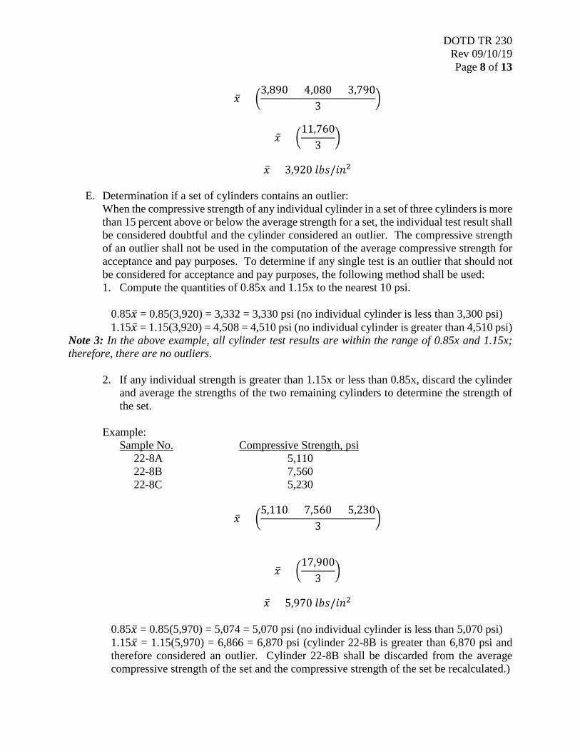
E. Determination if a set of cylinders contains an outlier:
When the compressive strength of any individual cylinder in a set of three cylinders is more than 15 percent above or below the average strength for a set, the individual test result shall be considered doubtful and the cylinder considered an outlier. The compressive strength of an outlier shall not be used in the computation of the average compressive strength for acceptance and pay purposes. To determine if any single test is an outlier that should not be considered for acceptance and pay purposes, the following method shall be used: 1. Compute the quantities of 0.85x and 1.15x to the nearest 10 psi.
0.85�̅�𝑥 = 0.85(3,920) = 3,332 = 3,330 psi (no individual cylinder is less than 3,300 psi) 1.15�̅�𝑥 = 1.15(3,920) = 4,508 = 4,510 psi (no individual cylinder is greater than 4,510 psi)
Note 3: In the above example, all cylinder test results are within the range of 0.85x and 1.15x; therefore, there are no outliers.
2. If any individual strength is greater than 1.15x or less than 0.85x, discard the cylinder and average the strengths of the two remaining cylinders to determine the strength of the set.
Example: Sample No. Compressive Strength, psi 22-8A 5,110 22-8B 7,560 22-8C 5,230
�̅�𝑥 = �5,110 + 7,560 + 5,230
3�
�̅�𝑥 = �17,900
3�
�̅�𝑥 = 5,970 𝑆𝑆𝑙𝑙𝐶𝐶/𝐷𝐷𝑖𝑖2
0.85�̅�𝑥 = 0.85(5,970) = 5,074 = 5,070 psi (no individual cylinder is less than 5,070 psi) 1.15�̅�𝑥 = 1.15(5,970) = 6,866 = 6,870 psi (cylinder 22-8B is greater than 6,870 psi and therefore considered an outlier. Cylinder 22-8B shall be discarded from the average compressive strength of the set and the compressive strength of the set be recalculated.)

DOTD TR 230 Rev 09/10/19 Page 9 of 13
Recalculation: Sample No. Compressive Strength, psi 22-8A 5,110 22-8C 5,230
�̅�𝑥 = �5,110 + 5,230
2�
�̅�𝑥 = �10,340
2�
�̅�𝑥 = 5,170 𝑆𝑆𝑙𝑙𝐶𝐶/𝐷𝐷𝑖𝑖2
0.85�̅�𝑥 = 0.85(5,170) = 4,394 = 4,390 psi (no individual cylinder is less than 4,390 psi) 1.15�̅�𝑥 = 1.15(5,170) = 5,946 = 5,950 psi (no individual cylinder is greater than 5,950 psi)
3. When the individual strengths of two (2) cylinders are greater than 1.15x or less than
0.85x, discard them. The strength of the remaining cylinder shall represent the strength of the set.
Example:
Sample No. Compressive Strength, psi 61-17A 4,990 61-17B 8,860 61-17C 10,540
�̅�𝑥 = �4,990 + 8,860 + 10,540
3�
�̅�𝑥 = �24,390
3�
�̅�𝑥 = 8,130 𝑆𝑆𝑙𝑙𝐶𝐶/𝐷𝐷𝑖𝑖2
0.85�̅�𝑥 = 0.85(8,130) = 6,010 psi (cylinder 61-17A is less than 6,010 psi and therefore considered an outlier.) 1.15�̅�𝑥 = 1.15(8,130) = 9,350 psi (cylinder 61-17C is greater than 9,350 psi and therefore considered an outlier.) Cylinders 61-17A and 61-17C shall be discarded from the average compressive strength of the set and the compressive strength of the remaining cylinder shall represent the strength of the set.

DOTD TR 230 Rev 09/10/19 Page 10 of 13
Recalculation:
Sample No. Compressive Strength, psi 61-17B 8,860
�̅�𝑥 = �8,860
1�
�̅�𝑥 = 8,860 𝑆𝑆𝑙𝑙𝐶𝐶/𝐷𝐷𝑖𝑖2
4. When the individual strengths of all cylinders in a set are greater than 1.15x or less than
0.85x, no average compressive strength for the lot shall be calculated. In this case, a further evaluation of the concrete represented shall be made.
Example: Sample No. Compressive Strength, psi 07-2A 4,400 07-2B 10,000 07-2C 11,550
�̅�𝑥 = �4,440 + 10,000 + 11,550
3�
�̅�𝑥 = �25,950
3�
�̅�𝑥 = 8,650 𝑆𝑆𝑙𝑙𝐶𝐶/𝐷𝐷𝑖𝑖2
0.85�̅�𝑥 = 0.85(8,650) = 7,350 psi (cylinder 07-2A is less than 7,350 psi and therefore considered an outlier.) 1.15�̅�𝑥 = 1.15(8,650) = 9,950 psi (both cylinders 07-2B and 07-2C are greater than 9,950 psi and therefore both considered outliers.) Cylinders 07-2A, 07-2B and 07-2C shall be discarded and further evaluation of the concrete represented shall be made.
F. When a lot consists of two sets of cylinders, the average compressive strength for the lot
shall be the arithmetic average of the average compressive strengths obtained for the two sets of cylinders. Example: Sample No. Average Compressive Strength, psi 03-6 3,920 22-8 5,170

DOTD TR 230 Rev 09/10/19 Page 11 of 13
�̅�𝑥 = �3,920 + 5,170
2�
�̅�𝑥 = �9,090
2�
�̅�𝑥 = 4,545 = 4,550 𝑆𝑆𝑙𝑙𝐶𝐶/𝐷𝐷𝑖𝑖2
VIII. Report The report shall include the following: 1. Sample Number (Specimen Identification). 2. Average Diameter of the Specimen to the nearest 0.01 in. 3. Cross-Sectional Area of the Specimen to the nearest 0.01 in.2.
Note 4: Area is a rounded value and used for informational purposes only. 4. Maximum Load indicated by the Testing Machine. 5. Compressive Strength to the nearest 10 psi. 6. Type of Fracture. 7. Defects in either Specimen or Cap. 8. Age of Specimen in Days.
IX. Normal Test Reporting Time Normal test reporting time is 4 hours from time of test.
DOTD TR 230 Rev 09/10/19 Page 12 of 13
Figure 1
Structural Concrete Tests (Blank)

DOTD TR 230 Rev 09/10/19 Page 13 of 13
Figure 2
Structural Concrete Tests (Example)