methods of carrying out the anticipative …
TRANSCRIPT

BULETINUL INSTITUTULUI POLITEHNIC DIN IAŞI Publicat de
Universitatea Tehnică „Gheorghe Asachi” din Iaşi Volumul 67 (71), Numărul 3, 2021
Secţia CONSTRUCŢII DE MAŞINI
METHODS OF CARRYING OUT THE ANTICIPATIVE MAINTENANCE OF FLUID HYDROCARBONS TRANSPORT
SYSTEMS
BY
ROBERT-GHEORGHE VLĂDESCU∗
Oil and Gas University of Ploiești, Faculty of Oil and Gas Ploiești, Romania
Received: March 31, 2021 Accepted for publication: June 29, 2021
The scientific knowledge, transposed into the engineering practice, requires
the collection, by using the most state-of-the-art and complete means of the information necessary for the decision to initiate the most appropriate measures of predictive maintenance.
In this context, the information provided as a result of the investigation of the pipelines intended for the transport of fluid hydrocarbons with smart pigging devices (cleaning, calibration, geometric, magnetic flux leakage) refers to those pre-existing in the questionnaire of the pipeline of the inspection operation. The values in the questionnaire are used to evaluate the anomalies in the inspection reports (preliminary and final).
A quantitative assessment of anomalies is based on, and limited exclusively to the results of the inspection, and does not include any numerical parameters (corrosion growth rates, anodic potential etc.), other than those from In-Line Inspection such as values Estimated Repair Factor (ERF) of anomalies.
The questionnaire (initial data provided) of the pipeline to be investigated with smart pigging devices includes at least: pipe diameter, wall thickness, pipe material, design pressure, Maximum Allowable Operating Pressure (MAOP), transported product, curve type, investigation history. The detection thresholds are applied in accordance with the manufacturing standards of the pipes.
∗Corresponding author; e-mail: [email protected]

40 Robert-Gheorghe Vlădescu
Generally, the calculation results, namely ERF and safe pressure, based on ASME B31G (Manual for Determining the Remaining Strength of Corroded Pipelines) are used to present the pipeline condition.
There are several approaches that can be used to characterize the behavior of corrosion anomalies, both pierced and partial. ASME B31G is a very conservative criterion that helps operators avoid unnecessary cuts. It is based on an empirical adequacy to an extensive series of tests on a full scale on vessels with narrow ridges.
Depth-based histograms show the distribution of all metal loss characteristics detected along the entire length of the pipe relative to their location and surface.
The approach to the referred issue allows the collection of essential information about the pipeline, and presents summaries of any anomalies of the pipeline, having a comprehensive character.
Keywords: predictive maintenance; smart pigging; In-Line Inspection; histograms; metal loss.
1. Introduction
General Considerations - Intelligent Go-Deviling
The information provided as a result of the investigation with intelligent go-devil (cleaning, calibration, geometric, MFL) is based on the pipeline questionnaire provided by the beneficiary prior to the inspection operation. The values in the questionnaire are used to evaluate the anomalies in the inspection reports (preliminary and final).
The anomalies detected and recorded during the inspection are individual metal leakage anomalies, circumferential welds, pipe leakage (lamination) and geometrical (Tudor and Râpeanu, 2002a).
The anomalies in lamination / fabrication are present in the pipeline from the moment of reception. It may be difficult to obtain a normal sizing accuracy for these depending on whether these anomalies are the result of hot or cold processing of the pipe steel. The laminations are initiated during the manufacturing process of the pipe and are formed due to defects such as non-metallic inclusions and casting defects, taking a laminar shape when hot rolled after casting (Bohni, 73).
A quantitative assessment of anomalies is based on, and limited exclusively to the results of the inspection, and does not include any numerical parameters (corrosion growth rates, anodic potential etc.) other than ILI results such as the ERF values of the anomalies.
The questionnaire (initial data provided) of the pipeline to be investigated with a smart go-devil includes at least: pipe diameter, wall

Bul. Inst. Polit. Iaşi, Vol. 67 (71), Nr. 3, 2021 41
thickness, pipe material, design pressure, MAOP, transported product, curve type, investigation history.
An inspection surveying consists of calibration, cleaning, MFL and combo inspection (CLP + IMU) of the pipeline and involves the following activities:
Preparation of instruments at the central unit (calibration and configuration correlated with the operating parameters of the pipeline):
‒ Test shooting and calibration; ‒ Field mobilization; ‒ Testing the pipe with the help of the calibration go-devil; ‒ Cleaning the pipe with go-devils; ‒ Pipe inspection with combo instrument (CLP + IMU); ‒ Inspection of the pipe with the MFL instrument; ‒ Preparation and submission of an express inspection report; ‒ Preparation and submission of a preliminary inspection report; ‒ Verification activities; ‒ Preparation and submission of a final inspection report.
2. Methodology of Using ILI
In general, ILI consists of: one (1) calibration run, cleaning run, one (1) combo run (CLP + IMU) and one (1) MFL inspection run.
The running of the calibration instrument is performed to ensure that there were no internal diameter (ID) reductions or other obstructions in the pipeline that could impede inspection activities. Calibration plates are designed to easily pass through difficult wall sections (curves / valves etc.) without touching the pipe wall, to indicate ID reductions only above acceptable limits.
The calibration vehicle is designed to perform three functions: ‒ Bending radius verification; ‒ Identification of the blows / obstructions; ‒ Checking the wall thickness changes / ID reductions. The speed of the calibration instrument is not measured on board, but
calculated based on the time required to complete the run. After running, a report is presented.

42 Robert-Gheorghe Vlădescu
Fig. 1 – Calibration Go-devil.
Calibration Go-devil (Fig. 1): A utility go-devil mounted with a
flexible metal plate or plates, to calibrate the inside diameter of the pipe. The conditions of the inlet of the pipe smaller than the diameter of the plate or the short radius bends will permanently deflect the material of the plate.
The cleaning run uses a magnetic brush (MBCT) and the BIDI cleaning pipes (Fig. 2).

Bul. Inst. Polit. Iaşi, Vol. 67 (71), Nr. 3, 2021 43
The speed of the cleaning tool is not measured on board, but calculated based on the time required to complete the run. After running, a report is presented. The total amount of waste received indicates whether or not another cleaning run is needed. Determining the acceptable quantity of waste to move on to subsequent go-devilation programs remains within the discretion of those conducting the internal inspection (correlation between diameter and length of pipe, accuracy of instruments used etc.).
Fig. 2 – MBCT Calibration.
Go-devil cleaning: A utility go-devil that uses cups, scraps or brushes to remove dirt, rust, lamination oxide and other debris from the pipe. Cleaning go-devils are used to increase the operating efficiency of a pipeline or to facilitate pipeline inspection.

44 Robert-Gheorghe Vlădescu
Combo Line Inspection (CLP + IMU) The acceptable speed range for combo inspection instruments (CLP +
IMU, Fig. 4) is 0.3 - 3.0 m/s. If the vehicle exceeds the specified maximum speed, the inspection performance may be inconclusive.
Fig. 3 – Geometry tool.
Geometry tool (Fig. 3): an in-line inspection tool that measures
deformations in the pipeline.
Fig. 4 – IMU - inertial measurement unit.

Bul. Inst. Polit. Iaşi, Vol. 67 (71), Nr. 3, 2021 45
MFL online inspection (Fig. 5) The acceptable speed range for MFL inspection instruments is 0.3 - 3.0 m/s.
If the vehicle exceeds the specified maximum speed, the inspection performance may be inconclusive.
Fig. 5 – Magnetic flux leakage.
A device or vehicle that uses a non-destructive testing technique to
inspect the pipeline from within or that uses sensors and other equipment to measure one or more characteristics of the pipeline. Also known as smart go-devil.
At the end of the runs it is checked that the MFL and combo inspection instruments (CLP + IMU) were received in good mechanical condition, with negligible wear on discs and cups. Also, immediately after receiving the two instruments, the collected data is downloaded and processed in the field. This operation is performed to confirm whether or not the recorded data covered the entire length of the pipeline and are suitable for further analysis in order to determine the integrity of the pipeline.
2.1. Characteristics of Corrosion
The detection thresholds are applied in accordance with the manufacturing standards of the pipes (Krause, 1976). The reporting and detection threshold values for metal loss anomalies and geometric anomalies are given in the Table 1, below.

46 Robert-Gheorghe Vlădescu
Table 1 Anomaly Evaluated
Description of the anomaly
Detective threshold
Reporting threshold
Metal loss anomalies
Length > 10 mm Width > 10 mm
Depth > 10% WT
Geometric anomalies
Depth> 0.5% OD
Depth > 0.5% OD
The significance of each metal corrosion loss (Fig. 6) anomaly is evaluated using the modified ASME B31G / ASME B31G pressure assessment formula.
Fig. 6 – Metal leakage.
The list of severe defects (losses of more than 50% of the metal) presents details of the anomalies identified in points with rules for selecting the characteristics. The list of severe defects includes the following:
‒ Feature number; ‒ Absolute distance at the beginning of the anomaly reported from the
launch (m); ‒ Circumferential welding upstream; ‒ The relative distance of the circumferential weld upstream from the
beginning of the anomaly (m); - Length of the joint (m); ‒ The type of feature according to the POF requirement; ‒ Identification of the characteristic according to the POF requirement; ‒ Classification of dimensions according to the POF requirement; ‒ Orientation (clockwise); ‒ Wall thickness for articles (mm); ‒ Axial length of the anomaly reported (mm); ‒ Reported anomaly width (mm);

Bul. Inst. Polit. Iaşi, Vol. 67 (71), Nr. 3, 2021 47
‒ Anomaly peak depth (% GP); ‒ Location on the surface of the pipeline; ‒ Calculated ERF value (ASME B31G); ‒ Calculated Psafe value (Bar) (ASME B31G); ‒ Calculated ERF value (mod. ASME B31G); ‒ Calculated Psafe value (Bar) (mod. ASME B31G); ‒ Selection rule; ‒ Number of groups; ‒ Coordinate (WG S84 / Stereo 70); ‒ Comments regarding the anomaly, if necessary.
2.2. Methodology for Evaluation of Data Obtained
The characteristics sheet for each anomaly presents details regarding the
predicted axial length (Fig. 7), width, peak depth and location details. In general, the calculation results (ERF and safe pressure) based on ASME B31G are used, as a more conservative criterion, it includes a schematic representation of the location of the anomaly relative to the welds of the joints and the orientation in the direction of flow. The location identified is related to the deepest point of the anomaly.
Fig. 7 ‒ Predicted axial length.

48 Robert-Gheorghe Vlădescu
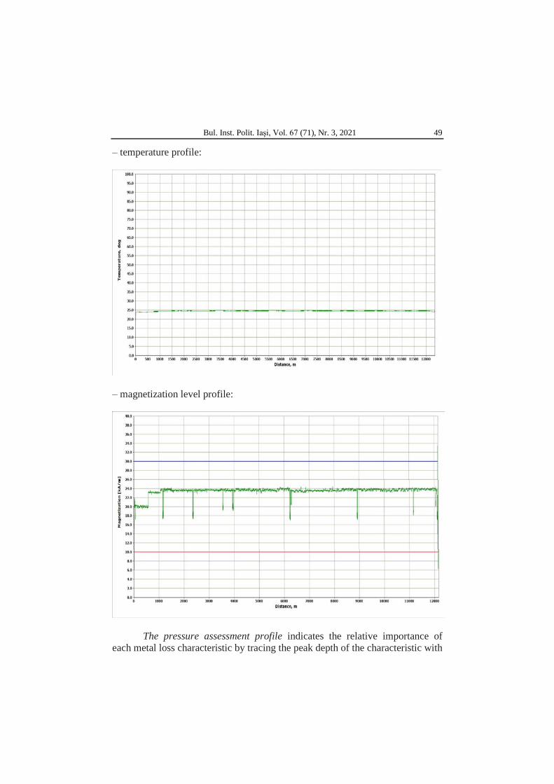
Loss profiles (sensor), temperature, MFL and combo speed (CLP + IMU) and MFL magnetization - examples for
‒ Sensor loss profile
‒ Speed profile:
Bul. Inst. Polit. Iaşi, Vol. 67 (71), Nr. 3, 2021 49
‒ temperature profile:
‒ magnetization level profile:
The pressure assessment profile indicates the relative importance of each metal loss characteristic by tracing the peak depth of the characteristic with

50 Robert-Gheorghe Vlădescu
respect to the predicted axial length and indicating on the graph the corresponding curve representing an ERF of 1. The metal loss characteristics with ERF values calculated as > 1.0 will be drawn above the curve. The more an anomaly is traced beyond the anomaly, the more important it is for the safe use of the pipeline. The ERF curve corresponds to the metal loss characteristics which must withstand a pressure equal to the declared MAOP multiplied by the applicable safety factor (Tullmin and Roberge, 1995).
The ASME B31G pressure rating is strictly applied to the isolated areas of corrosion in the central body of the line pipe operating at levels not exceeding 72%, the minimum specified tensile strength (SMYS). ASME B31G must not be used to evaluate corroded (circumferential and corded) welds or long complex interactive corrosion (Grafen, 1973).
There are several approaches that can be used to characterize the behavior of corrosion anomalies, both pierced and partial ones (Oniciu, 1986). ASME is a widely used manual to evaluate the remaining power of smooth corroded pipes. This supplement to the ASME B31G was developed over 25 years ago, although it has recently been issued again. ASME B31G is a very conservative criterion that helps operators avoid unnecessary cuts. It is based on an empirical adequacy to an extensive series of tests on a full scale on vessels with narrow ridges. The basis of the equation used in B31G is relatively simple and involves the following:
• The maximum circular deformation of the pipe is assumed to be equal to the tensile strength of the pipe material;
• Characterization of corrosion geometry through a parabolic shape designed for relatively short corrosion, and a rectangular shape for long corrosion. The parameters and dimensions of the anomaly (Fig. 8) are as follows:
L ‒ Length of metal loss; D ‒ specified outer diameter of pipe; t ‒ the thickness of the pipe wall.

Bul. Inst. Polit. Iaşi, Vol. 67 (71), Nr. 3, 2021 51
The modified ASME B31G is a less conservative criterion that helps operators avoid unnecessary cuts. It is based on an empirical adequacy to an extended series of full-scale tests on vessels with narrow ridges. The basis of the equation used in the modified B31G is relatively simple and involves the following:
• The maximum circular deformation of the pipe is assumed to be equal to the tensile strength of the pipe material.
• Supposed flow voltage SMYS plus 10 ksi 5y + 10 ksi. • Characterization of the corrosion geometry of the rectangular profile
with a depth of 0.85 from the maximum reported.
Ac = 0.85 dL
Fig. 8 – Measurement of anomaly.
This modification results in the change of the damage equation, which
also depends on the length of the anomaly. There are several limitations that must be considered when using
criterion B31.G: ‒ Depths of defects exceeding 80% of wall thickness (wt) This criterion
was developed for breaks of sections of corroded pipes and does not take into account the fact that the defect may have leaks. If the depth of a defect in a corrosion zone exceeds 80% wt, the section must be repaired or replaced (Zamfir et al., 1994).
‒ Depths of defects below 12.5% of wall thickness (wt) There is no limitation of the corrosion length when all measured depths are less than 12.5% wt. The reason is that in such a case it is expected to obtain the same remaining resistance as for a pipe that meets the minimum wall thickness for certain grades in the API.
‒ The actual surface is determined by the procedure which results in a minimum preset pressure. The iterative calculation procedure uses the corresponding lengths and depths of the corrosion pits to calculate an effective surface where the metal is missing and an effective length. These effective surfaces and effective lengths are used to calculate a preset pressure. The minimum preset pressure results from the iterative calculation and is presented as the maximum safety pressure for the corroded surface.

52 Robert-Gheorghe Vlădescu
Internal corrosion defects within the pipelines carrying liquid hydrocarbons are typically expected to be distributed at the bottom of the pipeline where it is possible to separate the free water from the oil-water emulsion (Fig. 9). Another positioning of them does not suggest an active internal corrosion in the pipe the accumulation of water is associated with, as long as all the defects are randomly distributed along the circumference and along the entire length of the pipe, thus, the internal corrosion defects reported are considered to be at the origin, before the pipeline commissioning, and are not representative for a corrosion during service (Hagymas et al., 1963).
Fig. 9 – Orentation of lenghts.
External corrosion control is achieved, mainly by using a bitumen insulation together with PVC or HDPE strips, intermediate layer of fiberglass. External insulation is applied both in the factory and in the field. The welded joints in the field are insulated with cold applied strips or heat shrink sleeves and for local repairs cold applied strips are used.
The pipeline is further protected with a cathodic protection system - injected current. CONPET uses the protection criterion -850 mV / 1000 mV changed to evaluate its performance.
The measurements of soil resistivity are between 2.77 Ωm and 675.46 Ωm along the entire pipeline; these values indicating that the aggressiveness of the soil, in the sense of corrosivity, ranges from low to extremely aggressive.
Taking into account the mentioned situation, the distribution of the external corrosion defects comprises several concentrations along the pipe, which appear extended throughout the circumference of the pipe, the greater depths e.g. ≥ 30% wt being predominantly located at the base - the lower half of the pipe. Insulation based on bitumen asphalt can be detached from the pipe due to the bending or bending at the base of the pipe. This can allow water / soil penetration into the space between the pipe and the insulation, which can lead to increased corrosion due to the shielding effect of the PC.

Bul. Inst. Polit. Iaşi, Vol. 67 (71), Nr. 3, 2021 53
In summary, the primary mechanism of increased corrosion in the pipe is considered to be due to the shielding effect of the PC due to the detachment of the insulation and / or the stones or other sharp objects that penetrated the insulation (Tudor and Râpeanu, 2002b).
Significant defects are those defects whose ERF is greater than 1 and the peak depth greater than 50% metal loss. Pressure-based histograms (based on ASME B31G) show the distribution of the most important characteristics along the entire length of the pipe. Each histogram shows the distribution along the pipeline of the metal loss characteristics with ERF values (Fig. 10) that fall within the chosen thresholds, e.g:
Fig. 10 – Distance from launcher.
Depth-based histograms (Fig. 11) show the distribution of all metal loss characteristics detected over the entire length of the pipe relative to their location and surface, e.g.:
Fig. 11 – Depth-based histograms.

54 Robert-Gheorghe Vlădescu
Five orientation and distribution traces are presented to illustrate the distribution of anomalies on the pipe surface:
‒ Distribution of all metal loss anomalies; ‒ Orientation profile of all metal loss anomalies along the entire length
of the pipe; ‒ Orientation profile of all anomalies of internal metal loss along the
entire length of the pipe; ‒ Orientation profile of all anomalies of external metal loss along the
entire length of the pipe (Fig. 12); ‒ Orientation profile of all metal loss anomalies as a function of
distance relative to the nearest circumferential weld (Fig. 13).
Fig. 12 – External defect vs internal defects.
Fig. 13 – Distribution clockwise of external defect vs internal defects.
3. Conclusions
3.1. Assessment of Corrosion Increase
The accuracy of the corrosion increase rate for the adapted defects depends on the accuracy in measuring / sizing the depth of each inspection instrument used. In relation to the specifications of the instrument, the corrosion
Bul. Inst. Polit. Iaşi, Vol. 67 (71), Nr. 3, 2021 55
defects are classified into 4 categories, depending on the type of corrosion as defined in the specification of the Pipeline Operators Forum (POF): general, pitting, axial crest, circumferential crest. The measurement accuracy for each instrument can be used to calculate the minimum corrosion rate, which could be considered statistically significant. The level of trust used depends on the nature of the evaluation. However, for corrosion enhancement studies, a 95% confidence level is typically used.
In addition to reporting metal losses, pipeline information presents summaries of any pipeline anomalies, location reference points, and comprehensive pipeline record.
Information is provided regarding the following: Adjacent metal objects report presents a list of details regarding the
location of all ferrous metal objects reported in close proximity to the pipe. These can damage the protective coating or cathodic protective system on the pipe and, over time, can also hit or damage the pipe (Oniciu and Constantinescu, 1982);
Geometric anomalies report presents a list detailing the location of all the hits, folds and ovalisations found along the pipeline. Also, where appropriate, there are the orientation drawings provided to indicate the distribution of the blow indications and the oval indications throughout the length of the pipes;
Welding anomalies report, such as lack of fusion, lack of penetration, cracks, etc. can be recorded in the inspection data. Where a type of anomaly cannot be conclusively classified, the anomaly will be identified only as "circumferential welding anomaly", "longitudinal welding anomaly" or as "spiral welding anomaly". The distribution of the anomalies of the circumferential welds is considered to be typically normal, with defects reported along the entire circumference and length of the pipe, without clear and visible concentrations.
Group list the group analysis is performed based on the POF standard, applying the following interaction rule (in two steps): Step 1: An anomaly (individual or part of a group) will never be grouped with another adjacent anomaly (individually or part of a group) if the distance is > = 6t. This applies to the axial and circumferential direction;
Step 2: The individual anomalies will be grouped when the axial spacing between the anomalies is below the shortest anomaly and the circumferential spacing is below the smallest anomaly width.
The repair list in the repair report presents a list that details the location of all repair covers (patches) and the underlying anomalies found along the pipeline.

56 Robert-Gheorghe Vlădescu
The list of landmark markers presents details on the location of Above Ground Markers (AGMs), magnets, main line valves, major withdrawals and anodes, where applicable, which have been identified along the pipeline. These reference points can be used to discover the position of anomalies and features along the pipeline.
The pipeline record is a comprehensive list of all circumferential welds, metal leakage characteristics, pipe fittings and pipeline anomalies found and identified during the inspection.
3.2. Methods of Defect Evaluation
There are several approaches that have been used to characterize the behavior of corrosion anomalies, both of those passing through the wall and of the partial ones.
‒ ASME B31G ASME is a widely used manual to assess the remaining power of
smooth corroded pipes. This supplement to the ASME B31G was developed over 25 years ago, although it was recently issued again. ASME B31G is a very conservative criterion that helps operators avoid unnecessary cuts. It is based on an empirical adequacy to an extensive series of tests on a full scale on vessels with narrow ridges. The basis of the equation used in B31G is relatively simple and involves the following:
• It is assumed that the maximum circular deformation of the pipe is equal to the tensile strength of the pipe material; and
• Characterization of corrosion geometry through a parabolic shape designed for relatively short corrosion, and a rectangular shape for long corrosion.
The most important elements calculated are: ‒ Calculation of the safe use pressure of the corroded area – Ps
Ps = PF / SF, (6)
where SF is the safety factor. The safety factor is considered to be 1.39 for pipes operating with a circular deflection of 72% of SMYS; however, there is not a single safety factor that is suitable for all types of pipeline construction, for all modes of pipeline operation, or for all types of faults or faults.
ASME B31G recommends a minimum safety factor equal to the minimum hydrostatic pressure rate required for the type of pipe construction at MAOP or MOP, but usually not less than 1.25.
‒ ERF calculation - The Estimated Repair Factor (ERF) associated with the metal loss anomaly is calculated using the following equation:
ERF = MAOP / Ps (7)

Bul. Inst. Polit. Iaşi, Vol. 67 (71), Nr. 3, 2021 57
MAOP is the maximum permissible operating pressure of the pipe. That is why, when the ERF is < 1, the anomaly is acceptable, and when the ERF is > 1, the anomaly is not acceptable according to ASME B31G and should be further analyzed using a less conservative evaluation procedure (e.g. RSTRENG, Finite Element Analysis, etc.) or the anomaly should be repaired using an approved procedure (e.g. replacement of the affected section or surrounding with a pressure retaining clip).
‒ Shannon - The evaluation method proposed by Shannon is based on the original NG-18 equation developed by Battelle but uses modified terms for the flow effort of the material. This provides a more accurate estimate of the effort at which metal loss defects give way to ductile pipe materials.
The blows reported by the internal inspection instruments are initially classified according to their association (or otherwise) with other defects of the pipeline to determine their significance, as follows:
‒ Simple smooth strokes ‒ Blows on circumferential welds or longitudinal welds ‒ Blows associated with corrosion ‒ Blows associated with mechanical damage * (MD), etc. An additional classification can be made after the location on the
circumference of the pipe: ‒ Blows located at the bottom of the pipe (between 4 and 8 o'clock) are
most likely blows caused by stones induced during construction. In this case, they resisted the hydrotesting before starting up and restricted to the flexion under cyclic pressure.
‒ Blows located at the top of the pipe (between 8 and 4 o'clock) can be caused during the service (excavator teeth, agricultural works etc.) and therefore are more likely to contain other defects such as holes and / or cracks (outside the capabilities of the inspection).
For the purpose of this assessment, the circumferential center of the blow was used to determine the location of the blow (up or down), being most likely where the printer acted on the pipe. In cases where the stroke width has not been reported, the classification of the orientation is based on the reported orientation.
It is emphasized that there are differences in the acceptance criteria of the blows in the oil and gas standards, for example in ASME B31.4 and B31.8. In addition, the risk of stroke fatigue due to cyclic pressure may be much more significant for a liquid pipe, compared to gas pipes, because the liquid pipes are typically much more subject to cyclic pressure. However, under static loading conditions it is considered that a blow would behave in the same way, regardless of the product of the pipe. Therefore, the criterion of the blow acceptance is based on both petroleum and gas recommendations.

58 Robert-Gheorghe Vlădescu
This is in line with the approach suggested by a recent review by the US Department of Transportation.
A summary of the relevant acceptance criteria (under static conditions) for each of the main types of hits is presented below:
Simple strokes - Most pipe standards allow single strokes up to 6% of
the outside diameter of the pipe (OD). However, the current recommendations in API 579 (2007) allow simple strokes up to 7% OD. This limitation is based on the tests carried out by the European Group for Pipeline Research (EPRG). Blows that exceed the base limit may be acceptable if a stress assessment demonstrates that they are subjected to a test below ≤ 6% (defined in ASME B31.8);
Blows on Welds - Blows that affect the curvature of a weld are
susceptible to cracks in the inner leg of the weld, particularly in the area of low hardness of the weld. ASME B31.4 does not allow hits on the weld, regardless of depth. However, both ASME B31.8 and DOT Part 192 standards state that hits located on ductile welds with ≤ 2% OD are acceptable. It is assumed that the welds comply with the typical construction specifications e.g. API 1104. There is no limit to the depth of impact for fragile welds such as acetylene welds or welds that can lead to fragile fractures e.g. welds performed before 1970 in ERW pipes. Blows greater than 2% OD deep at ductile welds can be accepted according to ASME B31.8, if a stress assessment shows that it does not exceed 4% and is shown to have an acceptable level of fatigue.
Blows Associated with Corrosion - In the standards for pipes different
acceptability criteria are presented for the evaluation of blow/ corrosion combinations. ASME B31.4, allows the association of a corrosion blow if it is proved that 87.5% of the nominal wall thickness remains. ASME B31.8 allows the association of a blow with corrosion, if it is proved that the corrosion defect is acceptable following the evaluation with an appropriate method e.g. ASME B31.G. Canadian Standardization Associate (CSA) Z662-07 (applicable to oil and gas pipelines) offers acceptance criteria similar to ASME B31.8, but is limited to corrosion with a depth ≤ 40% wt, which is accepted by ASME B31.G. It is emphasized that in the internal inspections, when crossing over a blow, this can cause the sensor to be lifted. Depending on the geometry of the blow, this may cause limiting the detection capability of the instrument in the accurate detection and measurement of metal loss or hollows associated with the blow. This is a recognized limitation of current in-house inspection technologies. Due to the limitations of the inspection capabilities, the depth limit of the corrosion 40% wt (adopted in CSA Z662-07), is considered the most suitable for the evaluation of the corrosions associated with the hits reported by the inspection instruments. Particular attention should be paid to the

Bul. Inst. Polit. Iaşi, Vol. 67 (71), Nr. 3, 2021 59
possibility that a hit associated with mechanical damage was mistakenly interpreted as corrosion. Further investigation is needed to classify metal loss as corrosion, particularly for the top of the pipe, where there is a high risk that metal loss will be due to mechanical damage. Excavation can be excluded if it can be demonstrated a low risk of third party intervention or corrosion is internal.
Blows Associated with Mechanical Damage - A blow associated with mechanical damage is potentially a serious defect given the fragile process of the pipe surface and often leads to cracks. Such blows can result in low bursting pressures and low lifetimes due to fatigue. The blows with cracks or hollows are not accepted by most standards, including ASME B31.8 and B31.4.
Blow Fatigue - The above evaluation criteria consider blows in static conditions, but if the pipe is subjected to significant internal cyclic pressure, an evaluation of fatigue should be considered. Blows located on welds or voltage concentrators can demonstrate short lifetimes compared to simple blows of the same magnitude. Simple, flat, unrestricted blows and greater than 2% OD that are free to flex in response to cyclic pressure and are considered a risk to fatigue. Unrestricted blows are most likely located at the top of the pipe. An evaluation of fatigue should be considered for the blows located in the areas where cyclical pressures frequently occur. In this case, the following prioritization is suggested:
1. Blows associated with welding or tension concentration at the top; 2. Blows> 2% OD at the top; 3. Double blows at the bottom; 4. Blows <2% OD on top; 5. Blows at the bottom.
The evaluation of the laminations is done according to the
methodology detailed in API 579 (2007). 'Part 13: Rolling Evaluation'. API 579 has three evaluation levels (Levels 1 to 3) that can be used for the assessment of laminations.
It is noteworthy that if the lamination has a component 'along the wall of the pipe' (not parallel to the surface) the lamination must be evaluated as a crack type defect, in accordance with the recommendations of API 579, Part 9.
The evaluation procedures of Levels 1 and 2 are projection criteria
based on the dimensions, orientation relative to the surface, interaction, distance and proximity to structural discontinuities. A summary of Level 1 is presented below: • Step 1: determine if there are surface bumps. If so, it is evaluated as bump. • Step 2: determine the required information. • Step 3: determine the space and the interaction according to the equation Ls > 2tc.

60 Robert-Gheorghe Vlădescu
• Step 4: if Lh≤ 0.09 max [s, c] proceed to step 5, otherwise it is evaluated as a crack type defect (API 579, Part 9). • Step 5: determine the thickness of the wall. • Step 6: if the following conditions are met, proceed to step 7, otherwise lamination is not acceptable according to Level 1. • There is no indication of lamination along the pipe wall • Lamination does not penetrate the surface according to the equation tmm≥ 0.10tc • The distance between the edges of the lamination and the nearest weld satisfies the equation; Lw ≥ max [2tc, 25 mm] • The distance between the laminar edges and the nearest major structural discontinuity satisfies the equation; Lmsd ≥ 1.8√Dtc • If the lamination is in service of hydrogen loading then the plane dimensions should satisfy the equations: s ≤ 0.6√Dtc & c ≤ 0.6√Dtc • Step 7: Determine the MAWP (Maximum Allowable Working Pressure).
The evaluation procedure at Level 2 is similar to Level 1, although there is a reduction in the criterion of the laminaries associated with welds or located in the hydrogen loading service. The evaluation in Level 3 consists of a detailed analysis of the stress / tension.
3.3. Procedure for Verification of Anomalies
The distance measuring system on the ground and that measured with
the smart instruments are two different measuring systems. The distance given by the intelligent instruments is derived from the meter of the instrument. The meter may have different results from the above ground system.
Significant differences can be caused by both systems: above-ground measurements take into account topography and do not necessarily include pipeline curvature geometry or similar characteristics. Odometer wheel skidding or debris may affect meter-based measurements but in many cases they can be recalibrated using pipeline records or other information. In order to find the anomalies detected by the MFL in-line inspection instruments, it is necessary to make correct distance measurements from the appropriate reference points.
It is recommended that the measurements be made with a tape measure that has at least 50 m. Optical or laser instruments can also be used. However, the discovery tools do not take into account the real landscape profile and this can cause errors when it comes to measuring long distances. It is essential that for each section of a pipeline for which an excavation check is scheduled, the distance between the reference points will be measured and, if required, the necessary corrections will be made, corrections which will be taken into account for subsequent measurements.
In case it is difficult to measure from the reference points, intermediate reference points can be used. One can use as intermediate reference points:

Bul. Inst. Polit. Iaşi, Vol. 67 (71), Nr. 3, 2021 61
short curves or pipes, changes in the thickness of the pipe wall or changes in the types of pipes, insulation repairs, nuts, etc.After completing the anomaly verification, anomaly verification forms must be completed, which include their actual parameters, dimensions, location on the pipeline but also the length of the excavated pipe sections.
The basic procedure - locating a feature - starting from the identification of the nearest installation (in the typical case it is the first valve in the launch station go-devil or other t-fittings, valves) as well as markers above the ground or the magnetic ones mounted on the pipe. Other installations are not used as reference. If the GPS device owned is efficient, the location can be done by entering the coordinates of the defect and determining it. The only accepted error is the axial max. 0.4 m.
The basic procedure - the measurement of the characteristics - the pipe is cleaned, preferably by blasting, the depth, the length and the width of the anomaly are measured. The defect is marked and the distance to the circumferential weld is measured.
REFERENCES
Bohni H., Probleme ale coroziunii metalelor. Coroziunea. Protejarea suprafețelor, 1973.
Grafen H., Rezistența generată la coroziune a cusăturilor sudate, supuse la eforturi și la oboseală, Coroziunea. Protejarea suprafețelor, 1973.
Hagymas G., Firoiu C., Radovici O., Coroziunea și protecția metalelor, Editura Tehnică, București, 1963.
Krause J., Influența factorilor atmosferici asupra coroziunii fierului și oțelului, Coroziunea și protecția anticorozivă, Edit. IDT, București, 1976.
Oniciu L., Coroziunea metalelor. Aspecte fundamentale și protecția anticorozivă, Edit. Științifică și Enciclopedică, București, 1986.
Oniciu L., Constantinescu E., Electrochimie și coroziune, Edit. Didactică și Pedagogică, București, 1982.
Tudor I., Râpeanu R.G., Ingineria coroziunii, Vol. I, Edit. Universității din Ploiești, 2002a.
Tudor I., Râpeanu R.G., Ingineria coroziunii, Vol. II, Edit. Universității din Ploiești, 2002b.
Tullmin M., Roberge P.R., Corrosion of metallic materials, Reliability, IEEE Transactions, 1995.
Zamfir S., Vidu R., Brânzoi V., Coroziunea materialelor, Edit. Didactică și Pedagogică, București, 1994.

62 Robert-Gheorghe Vlădescu
METODE DE REALIZARE A MENTENANȚEI ANTICIPATIVE A
SISTEMELOR DE TRANSPORT HIDROCARBURI FLUIDE
(Rezumat)
Cunoașterea științifică, transpusă în practica inginerească, impune colectarea prin cele mai moderne și complete mijloace a informațiilor necesare deciziei de inițiere a celor mai adecvate măsuri de mentenanță predictivă.
În context, informațiile furnizate ca urmare a investigării conductelor destinate transportului hidrocarburilor fluide cu godevil inteligent (curaţare, calibrare, geometric, Magnetic flux leakage) se raportează la cele preexistente în chestionarul conductei operațiunii de inspecție. Valorile din chestionar sunt utilizate pentru evaluarea anomaliilor în rapoartele de inspecție (preliminar și final).
O evaluare cantitativă a anomaliilor este bazată pe, și limitatӑ exclusiv la rezultatele inspecției, și nu include niciun fel de parametri numerici (rate de creștere a coroziunii, potențial anodic etc.), altele decât cele provenite din In-line Inspection cum ar fi valorile Estimated Repair Factor (ERF) ale anomaliilor.
Chestionarul (datele inițiale furnizate) conductei ce urmează a fi investigată cu godevil inteligent cuprinde minim: diametrul conductei, grosimea de perete, materialul conductei, presiunea de proiectare, Maximum Allowable Operating Pressure (MAOP), produsul transportat, tipul curbelor, istoric al investigațiilor. Pragurile de depistare sunt aplicate în conformitate cu standardele de fabricație a conductelor.
În general, pentru prezentarea stării conductei se folosesc rezultatele de calcul, și anume ERF și presiune sigură, bazate pe ASME B31G (Manual for Determining the Remaining Strength of Corroded Pipelines).
Există mai multe abordări care pot fi folosite pentru a caracteriza comportamentul anomaliilor de coroziune, atât a celor străpunse cât și a celor parțiale. ASME este un manual folosit pe scară largă în scopul de a evalua rezistența rămasă a conductelor corodate neted. ASME B31G este un criteriu foarte conservator care ajută pe operatori să evite decupări inutile. Se bazează pe o adecvare empirică la o serie extinsă de teste pe conducte cu crestături înguste.
Histogramele bazate pe adâncime prezintă distribuția tuturor caracteristicilor de pierdere de metal depistate pe întreaga lungime a conductei relativ la locația și suprafața acestora.
Modul de abordare a problematicii referite permite colectarea de informații esențiale cu privire la conductă și prezintă rezumate ale oricăror anomalii ale conductei, având caracter comprehensiv.