methods of flight-path planning for uav photogrammetry ... · additionally, for planning...
TRANSCRIPT
CEAS 2015 paper no.23 Page | 1 This work is licensed under the Creative Commons Attribution International License (CC BY). Copyright © 2015 by author(s).
Methods of flight-path planning for UAV photogrammetry missions with consideration of aircraft dynamic properties
Dominik Glowacki Warsaw University of Technology, Warsaw, Poland Nowowiejska 24, 00-665 Warsaw, Poland [email protected] Jaroslaw Hajduk Air Force Institute of Technology Księcia Bolesława 6, 01-494 Warszawa [email protected] Mirosław Rodzewicz Warsaw University of Technology, Warsaw, Poland Nowowiejska 24, 00-665 Warsaw, Poland [email protected] ABSTRACT
The intention of authors' presenting this paper is to share experience of photogrammetry missions carried by the UAV in severe Antarctic conditions. Relevant knowledge was gained by participation in the Polish-
Norwegian Research project named MONICA (oriented on aerial monitoring of the impact of climate
change on the Antarctic ecosystems). The basic aim of the photogrammetry mission is to provide the ortophotomaps, which consist of a set of merged photos. There are several factors that contribute to
achieving successful results from photogrammetry missions, namely parameters and space-orientation of the photogrammetric grid together with quality and resolution of the photos. The effectiveness of
photogrammetry work depends on dynamic properties of the UAV and the accuracy of the flight trajectory flown over projected Photogrametric grid. This accuracy is influenced by elements such as wind
and turbulence. Another important problem in question is programming the turns at the ends of the
photogrammetric-grid lines by inserting the net of some additional points in those lines. It helps the navigation systems to follow a fixed flight path after each turn. In relation to that, the authors present
some methods of flight-path planning with either their advantages or disadvantages.
1 INTRODUCTION
The UAS (Unmanned Aerial Systems), which utilize very light and small unmanned aircrafts in photogrammetric applications became a very useful supplement for the classic aerial photogrammetry
systems, and are preferred for flight-missions over small areas (up to 20 km2). Lightweight unmanned aircraft allows for the effective collection of photogrammetry data with significantly reduced cost in
comparison to general aviation aircraft usage [1, 2, 3], but they also have some crucial limitations, for example: limited operational range and susceptibility to windy weather conditions. In order to increase
the effectiveness of photogrametrics missions, proper planning of the flight-paths has the crucial
importance [4]. It was a very important problem in such a unique event, as photogrammetry missions in King George Island placed in Antarctica. They were performed within the research project titled: “A novel
approach to monitoring the impact of climate change on Antarctic ecosystems” (acronym MONICA). This project is carried out by the consortium consisting of Polish Academy of Sciences, Warsaw University of
CEAS 2015 paper no.23 Page | 2 This work is licensed under the Creative Commons Attribution International License (CC BY). Copyright © 2015 by author(s).
Technology and Northern Research Institute from Tromso (Norwey), and is supplied by Norwegian
Financial Mechanism administrated by National Center of Research and Development. MONICA has two aims: Aerial monitoring of ASPA 128 & ASPA 151 (Antarctic Specially Protected Areas), and input-data
collection for making ortophotomaps of ASPA 128 & ASPA 151.
2 BASIC REQUIREMENTS REGARDING PHOTOGRAMMETRY
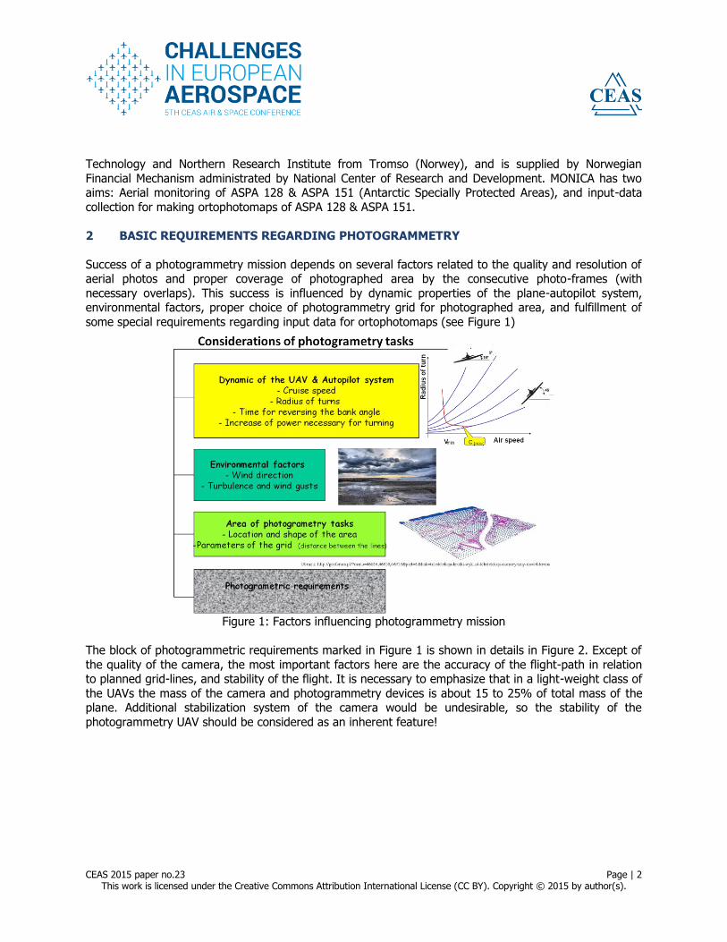
Success of a photogrammetry mission depends on several factors related to the quality and resolution of aerial photos and proper coverage of photographed area by the consecutive photo-frames (with
necessary overlaps). This success is influenced by dynamic properties of the plane-autopilot system, environmental factors, proper choice of photogrammetry grid for photographed area, and fulfillment of
some special requirements regarding input data for ortophotomaps (see Figure 1)
Figure 1: Factors influencing photogrammetry mission
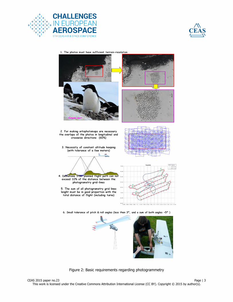
The block of photogrammetric requirements marked in Figure 1 is shown in details in Figure 2. Except of
the quality of the camera, the most important factors here are the accuracy of the flight-path in relation to planned grid-lines, and stability of the flight. It is necessary to emphasize that in a light-weight class of
the UAVs the mass of the camera and photogrammetry devices is about 15 to 25% of total mass of the plane. Additional stabilization system of the camera would be undesirable, so the stability of the
photogrammetry UAV should be considered as an inherent feature!
CEAS 2015 paper no.23 Page | 3 This work is licensed under the Creative Commons Attribution International License (CC BY). Copyright © 2015 by author(s).
Figure 2: Basic requirements regarding photogrammetry
CEAS 2015 paper no.23 Page | 4 This work is licensed under the Creative Commons Attribution International License (CC BY). Copyright © 2015 by author(s).
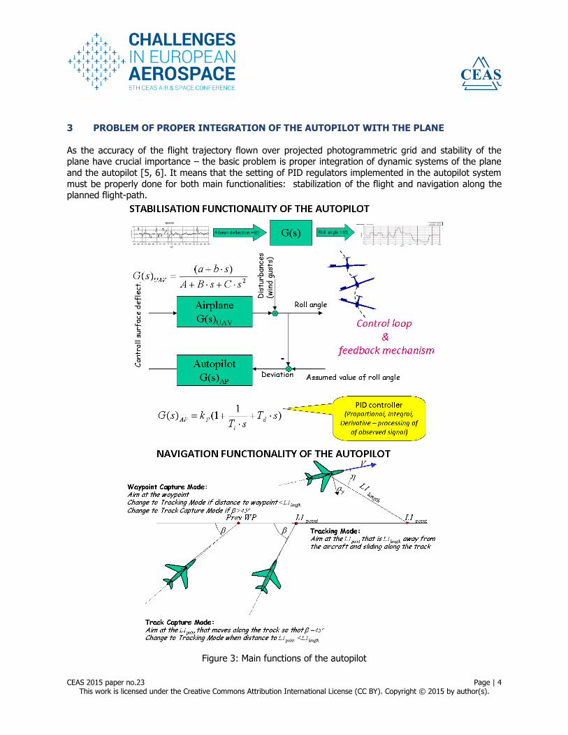
3 PROBLEM OF PROPER INTEGRATION OF THE AUTOPILOT WITH THE PLANE
As the accuracy of the flight trajectory flown over projected photogrammetric grid and stability of the plane have crucial importance – the basic problem is proper integration of dynamic systems of the plane
and the autopilot [5, 6]. It means that the setting of PID regulators implemented in the autopilot system
must be properly done for both main functionalities: stabilization of the flight and navigation along the planned flight-path.
Figure 3: Main functions of the autopilot
CEAS 2015 paper no.23 Page | 5 This work is licensed under the Creative Commons Attribution International License (CC BY). Copyright © 2015 by author(s).
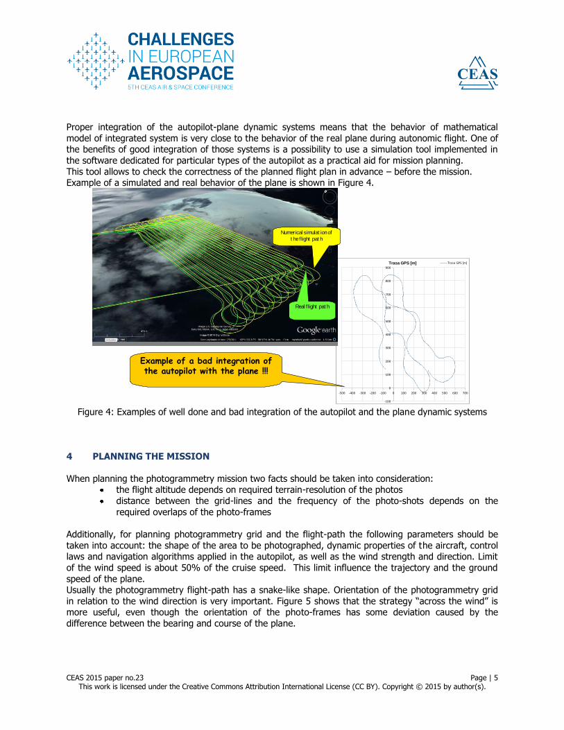
Proper integration of the autopilot-plane dynamic systems means that the behavior of mathematical
model of integrated system is very close to the behavior of the real plane during autonomic flight. One of the benefits of good integration of those systems is a possibility to use a simulation tool implemented in
the software dedicated for particular types of the autopilot as a practical aid for mission planning.
This tool allows to check the correctness of the planned flight plan in advance – before the mission. Example of a simulated and real behavior of the plane is shown in Figure 4.
Trasa GPS [m]
-100
0
100
200
300
400
500
600
700
800
900
-500 -400 -300 -200 -100 0 100 200 300 400 500 600 700
Trasa GPS [m]
Example of a bad integration of the autopilot with the plane !!!
Numerical simulat ion of
t he flight pat h
Real flight pat h
Numerical simulat ion of
t he flight pat h
Real flight pat h
Figure 4: Examples of well done and bad integration of the autopilot and the plane dynamic systems
4 PLANNING THE MISSION
When planning the photogrammetry mission two facts should be taken into consideration: the flight altitude depends on required terrain-resolution of the photos
distance between the grid-lines and the frequency of the photo-shots depends on the
required overlaps of the photo-frames
Additionally, for planning photogrammetry grid and the flight-path the following parameters should be
taken into account: the shape of the area to be photographed, dynamic properties of the aircraft, control laws and navigation algorithms applied in the autopilot, as well as the wind strength and direction. Limit
of the wind speed is about 50% of the cruise speed. This limit influence the trajectory and the ground
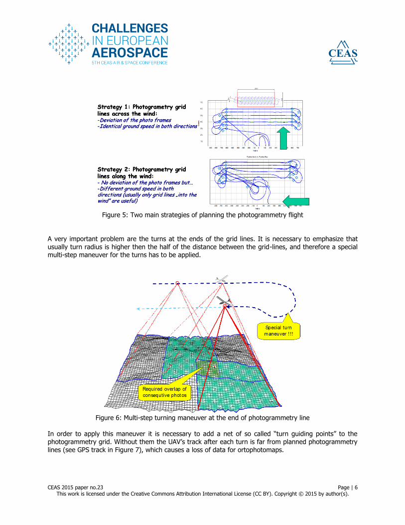
speed of the plane. Usually the photogrammetry flight-path has a snake-like shape. Orientation of the photogrammetry grid
in relation to the wind direction is very important. Figure 5 shows that the strategy “across the wind” is more useful, even though the orientation of the photo-frames has some deviation caused by the
difference between the bearing and course of the plane.
CEAS 2015 paper no.23 Page | 6 This work is licensed under the Creative Commons Attribution International License (CC BY). Copyright © 2015 by author(s).
Strategy 1: Photogrametry grid lines across the wind:-Deviation of the photo frames-Identical ground speed in both directions
Strategy 2: Photogrametry grid lines along the wind:- No deviation of the photo frames but...-Different ground speed in both directions (usually only grid lines „into the wind” are useful)
Figure 5: Two main strategies of planning the photogrammetry flight
A very important problem are the turns at the ends of the grid lines. It is necessary to emphasize that
usually turn radius is higher then the half of the distance between the grid-lines, and therefore a special multi-step maneuver for the turns has to be applied.
Figure 6: Multi-step turning maneuver at the end of photogrammetry line
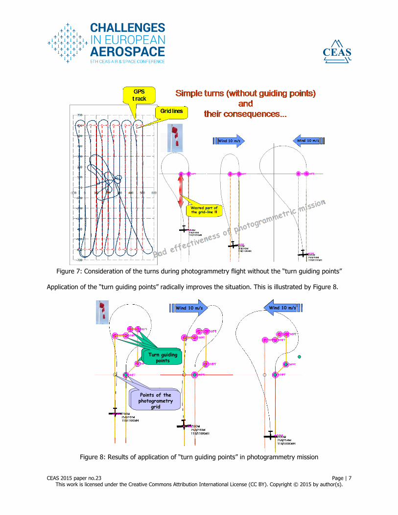
In order to apply this maneuver it is necessary to add a net of so called “turn guiding points” to the
photogrammetry grid. Without them the UAV’s track after each turn is far from planned photogrammetry
lines (see GPS track in Figure 7), which causes a loss of data for ortophotomaps.
CEAS 2015 paper no.23 Page | 7 This work is licensed under the Creative Commons Attribution International License (CC BY). Copyright © 2015 by author(s).
Figure 7: Consideration of the turns during photogrammetry flight without the “turn guiding points”
Application of the “turn guiding points” radically improves the situation. This is illustrated by Figure 8.
Wind 10 m/s Wind 10 m/s
Turn guidingpoint
Points of the photogrametry
grid
Points of the photogrametry
grid
Turn guidingpoints
Turn guidingpoint
Turn guidingpoint
Turn guidingpoints
Wind 10 m/s Wind 10 m/sWind 10 m/sWind 10 m/s Wind 10 m/sWind 10 m/s
Turn guidingpoint
Points of the photogrametry
grid
Points of the photogrametry
grid
Turn guidingpoints
Turn guidingpoint
Turn guidingpoint
Turn guidingpoints
Figure 8: Results of application of “turn guiding points” in photogrammetry mission
CEAS 2015 paper no.23 Page | 8 This work is licensed under the Creative Commons Attribution International License (CC BY). Copyright © 2015 by author(s).
As one can see, also in this case the orientation of the “turn guiding points” net in relation to the wind is very important, because improper orientation causes the UAV to leave the desired flight path (see the
case on the right side of Figure 8).
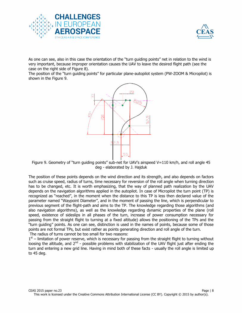
The position of the “turn guiding points” for particular plane-autopilot system (PW-ZOOM & Micropilot) is shown in the Figure 9.
Figure 9. Geometry of “turn guiding points” sub-net for UAV’s airspeed V=110 km/h, and roll angle 45
deg - elaborated by J. Hajduk
The position of these points depends on the wind direction and its strength, and also depends on factors
such as cruise speed, radius of turns, time necessary for reversion of the roll angle when turning direction has to be changed, etc. It is worth emphasizing, that the way of planned path realization by the UAV
depends on the navigation algorithms applied in the autopilot. In case of Micropilot the turn point (TP) is
recognized as “reached”, in the moment when the distance to this TP is less then declared value of the parameter named “Waypoint Diameter”, and in the moment of passing the line, which is perpendicular to
previous segment of the flight-path and aims to the TP. The knowledge regarding those algorithms (and also navigation algorithms), as well as the knowledge regarding dynamic properties of the plane (roll
speed, existence of sideslips in all phases of the turn, increase of power consumption necessary for
passing from the straight flight to turning at a fixed altitude) allows the positioning of the TPs and the “turn guiding” points. As one can see, distinction is used in the names of points, because some of those
points are not formal TPs, but exist rather as points generating direction and roll angle of the turn. The radius of turns cannot be too small for two reasons:
1st – limitation of power reserve, which is necessary for passing from the straight flight to turning without loosing the altitude, and 2nd - possible problems with stabilization of the UAV flight just after ending the
turn and entering a new grid line. Having in mind both of these facts - usually the roll angle is limited up
to 45 deg.
CEAS 2015 paper no.23 Page | 9 This work is licensed under the Creative Commons Attribution International License (CC BY). Copyright © 2015 by author(s).
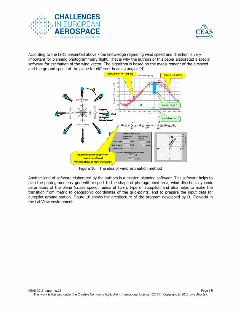
According to the facts presented above - the knowledge regarding wind speed and direction is very
important for planning photogrammetry flight. That is why the authors of this paper elaborated a special software for estimation of the wind vector. The algorithm is based on the measurement of the airspeed
and the ground speed of the plane for different heading angles [4].
Figure 10: The idea of wind estimation method
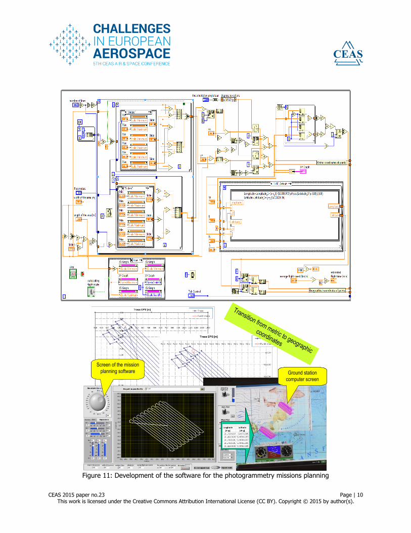
Another kind of software elaborated by the authors is a mission planning software. This software helps to plan the photogrammetry grid with respect to the shape of photographed area, wind direction, dynamic
parameters of the plane (cruise speed, radius of turn), type of autopilot, and also helps to make the
transition from metric to geographic coordinates of the grid-points, and to prepare the input data for autopilot ground station. Figure 10 shows the architecture of the program developed by D. Glowacki in
the LabView environment.
CEAS 2015 paper no.23 Page | 10 This work is licensed under the Creative Commons Attribution International License (CC BY). Copyright © 2015 by author(s).
D. Głowacki Ph.D.
Transition from metric to geographic
coordinates
Ground station
computer screen
Screen of the mission
planning software
D. Głowacki Ph.D.
Transition from metric to geographic
coordinates
Ground station
computer screen
Screen of the mission
planning software
Figure 11: Development of the software for the photogrammetry missions planning
CEAS 2015 paper no.23 Page | 11 This work is licensed under the Creative Commons Attribution International License (CC BY). Copyright © 2015 by author(s).
5 IMPLEMENTATION OF METHODS DEVELOPED BY AUTHORS IN PHOTOGRAMMETRY
MISSIONS IN ANTARCTICA
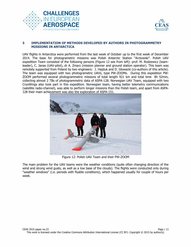
UAV flights in Antarctica were performed from the last week of October up to the first week of December
2014. The base for photogrametric missions was Polish Antarctic Station “Arctowski”. Polish UAV
expedition Team consisted of the following persons (Figure 12 see from left): prof. M. Rodzewicz (team-leader), C. Janas (UAV-pilot), dr A. Zmarz (mission planner and ground station operator). This team was
remotely supported from Poland by two engineers: J. Hajduk and D. Glowacki (co-authors of this article). The team was equipped with two photogrametric UAVs, type PW-ZOOMs. During this expedition PW-
ZOOM performed several photogrammetric missions of total length 921 km and total time 8h 52min, collecting almost 2 TBs of photogrammetric data of ASPA-128. Norwegian UAV Team, equipped with two
CryoWings also took part in this expedition. Norwegian team, having better telemetry communications
(satellite radio-channel), was able to perform longer missions than the Polish team, and apart from ASPA-128 their main achievement was also the exploration of ASPA-151.
Figure 12: Polish UAV Team and their PW-ZOOM
The main problem for the UAV teams were the weather conditions (quite often changing direction of the wind and strong wind gusts, as well as a low base of the clouds). The flights were conducted only during
“weather windows” (i.e. periods with flyable conditions), which happened usually for couple of hours per week.
CEAS 2015 paper no.23 Page | 12 This work is licensed under the Creative Commons Attribution International License (CC BY). Copyright © 2015 by author(s).
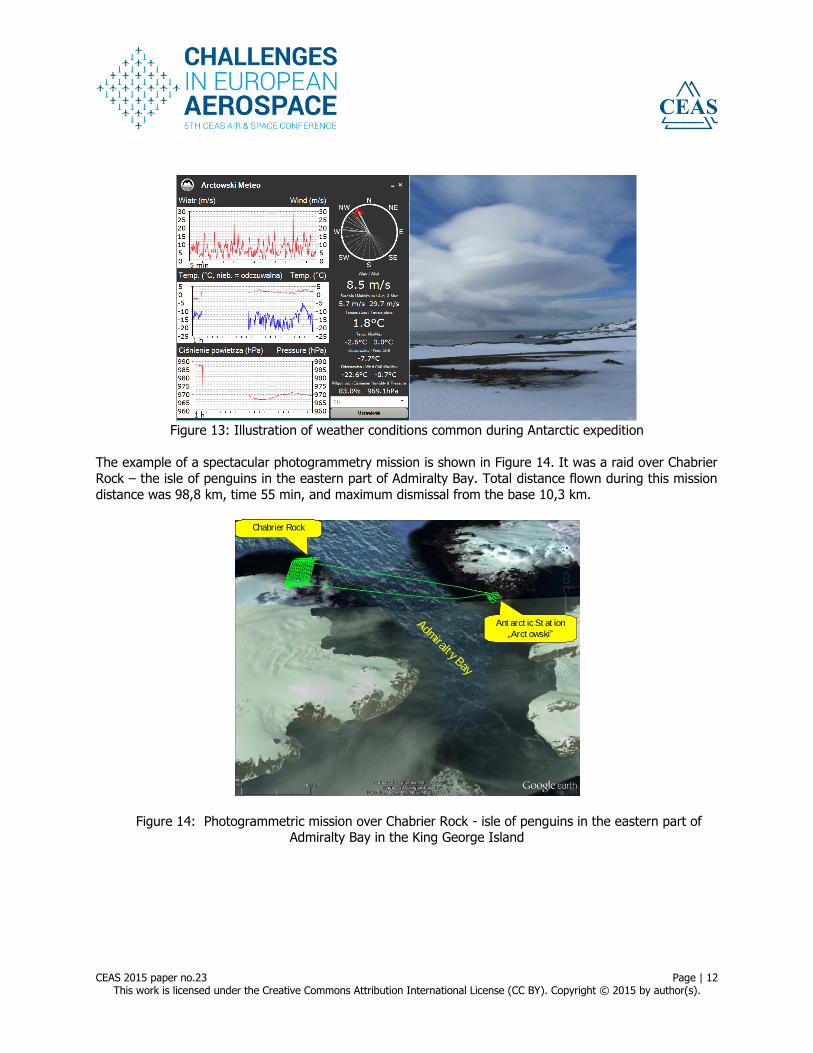
Figure 13: Illustration of weather conditions common during Antarctic expedition
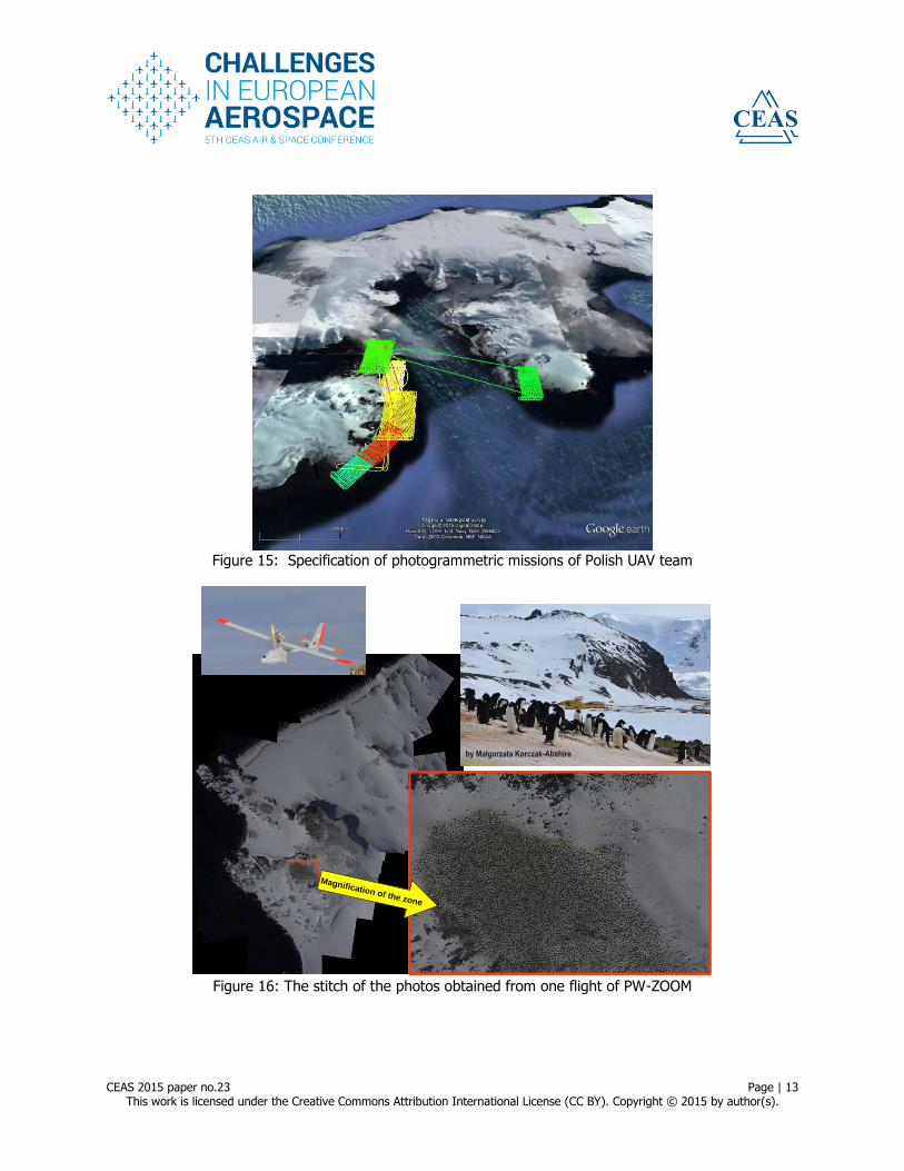
The example of a spectacular photogrammetry mission is shown in Figure 14. It was a raid over Chabrier
Rock – the isle of penguins in the eastern part of Admiralty Bay. Total distance flown during this mission
distance was 98,8 km, time 55 min, and maximum dismissal from the base 10,3 km.
Admiralt y Bay
Ant arct ic St at ion
„Arct owski”
Chabrier Rock
Admiralt y Bay
Ant arct ic St at ion
„Arct owski”
Chabrier Rock
Figure 14: Photogrammetric mission over Chabrier Rock - isle of penguins in the eastern part of Admiralty Bay in the King George Island
CEAS 2015 paper no.23 Page | 13 This work is licensed under the Creative Commons Attribution International License (CC BY). Copyright © 2015 by author(s).
Figure 15: Specification of photogrammetric missions of Polish UAV team
by Małgorzata Korczak-Abshire
Magnification of the zone
by Małgorzata Korczak-Abshireby Małgorzata Korczak-Abshire
Magnification of the zone
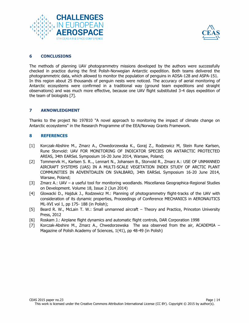
Figure 16: The stitch of the photos obtained from one flight of PW-ZOOM
CEAS 2015 paper no.23 Page | 14 This work is licensed under the Creative Commons Attribution International License (CC BY). Copyright © 2015 by author(s).
6 CONCLUSIONS
The methods of planning UAV photogrammetry missions developed by the authors were successfully checked in practice during the first Polish-Norwegian Antarctic expedition. Both teams delivered the
photogrammetric data, which allowed to monitor the population of penguins in ADSA-128 and ASPA-151.
In this region about 25 thousands of penguin nests were noticed. The accuracy of aerial monitoring of Antarctic ecosystems were confirmed in a traditional way (ground team expeditions and straight
observations) and was much more effective, because one UAV flight substituted 3-4 days expedition of the team of biologists [7].
7 AKNOWLEDGMENT
Thanks to the project No 197810 "A novel approach to monitoring the impact of climate change on
Antarctic ecosystems" in the Research Programme of the EEA/Norway Grants Framework.
8 REFERENCES
[1] Korczak-Abshire M., Zmarz A., Chwedorzewska K., Goraj Z., Rodzewicz M, Stein Rune Karlsen,
Rune Storvold: UAV FOR MONITORING OF INDICATOR SPECIES ON ANTARCTIC PROTECTED
AREAS, 34th EARSeL Symposium 16-20 June 2014, Warsaw, Poland;
[2] Tommervik H., Karlsen S. R.., Lennart N., Johansen B., Storvold R., Zmarz A.: USE OF UNMANNED
AIRCRAFT SYSTEMS (UAS) IN A MULTI-SCALE VEGETATION INDEX STUDY OF ARCTIC PLANT
COMMUNITIES IN ADVENTDALEN ON SVALBARD, 34th EARSeL Symposium 16-20 June 2014,
Warsaw, Poland;
[3] Zmarz A.: UAV – a useful tool for monitoring woodlands. Miscellanea Geographica-Regional Studies
on Development. Volume 18, Issue 2 (Jun 2014)
[4] Glowacki D., Hajduk J., Rodzewicz M.: Planning of photogrammetry flight-tracks of the UAV with
consideration of its dynamic properties, Proceedings of Conference MECHANICS in AERONAUTICS
ML-XVI vol 1, pp 175- 188 (in Polish);
[5] Beard R. W., McLain T. W.: Small unmanned aircraft – Theory and Practice, Princeton University
Press, 2012
[6] Roskam J.: Airplane flight dynamics and automatic flight controls, DAR Corporation 1998
[7] Korczak-Abshire M., Zmarz A., Chwedorzewska The sea observed from the air, ACADEMIA –
Magazine of Polish Academy of Sciences, 1(41), pp 48-49 (in Polish)