methods of measuring residual stresses in...
TRANSCRIPT
1
Methods of Measuring Residual Stresses in Components
N. S. Rossinia,b, M. Dassistia, K. Y. Benyounisb and A. G. Olabib
a- Mechanical and Management Engineering Department, Politecnico di Bari, Viale Japigia 182, 70126 Bari-Italy b- Material Processing Research Centre, School of Mech. & Manu. Eng., Dublin City University, Dublin 9, Ireland. Tel: +353-1-7005000
[email protected]; [email protected]; [email protected]; [email protected]
Abstract
Residual stresses occur in many manufactured structures and components. Large number of
investigations have been carried out to study this phenomenon and its effect on the mechanical
characteristics of these components.
Over the years, different methods have been developed to measure residual stress for different types
of components in order to obtain reliable assessment. The various specific methods have evolved
over several decades and their practical applications have greatly benefited from the development of
complementary technologies, notably in material cutting, full-field deformation measurement
techniques, numerical methods and computing power. These complementary technologies have
stimulated advances not only in measurement accuracy and reliability, but also in range of
application; much greater detail in residual stresses measurement is now available. This paper aims
to classify the different residual stresses measurement methods and to provide an overview of some
of the recent advances in this area to help researchers on selecting their techniques among
destructive, semi destructive and non destructive techniques depends on their application and the
availabilities of those techniques. For each method scope, physical limitation, advantages and
disadvantages are summarized. In the end this paper indicates some promising directions for future
developments.
Keywords: Residual stresses, X-Ray diffraction, Hole-Drilling Method
1. Introduction
The engineering properties of materials and structural components, notably fatigue life,
distortion, dimensional stability, corrosion resistance, and brittle fracture can be considerably
influenced by residual stresses [1]. Such effects usually bring to considerable expenditure in repairs
and restoration of parts, equipment, and structures. Accordingly, residual stresses analysis is a
2
compulsory stage in the design of parts and structural elements and in the estimation of their
reliability under real service conditions. Systematic studies had shown that, for instance, welding
residual stresses might lead to a drastic reduction in the fatigue strength of welded elements. In
multicycle fatigue (N > 106 cycles), the effect of residual stresses can be comparable to the effect of
stress concentration [2]. Surprisingly, significant are the effect of residual stresses on the fatigue life
of welded elements as regards relieving harmful tensile residual stresses and introducing beneficial
compressive residual stresses in the weld toe zones. Currently, the residual stresses are one of the
main factors determining the engineering properties of materials, pats, and welded elements, and
should be taken into account during the design and manufacturing of different products. Although
successful progress has been achieved in the development of techniques for residual stresses
management, considerable effort is still required to develop efficient and cost-effective methods of
residual stress measurement and analysis as well as technologies for the beneficial redistribution of
residual stresses.
1.1 Definition and classification of residual stresses
Residual stresses can be defined as the stresses that remain within a material or body after
manufacture and material processing in the absence of external forces or thermal gradients. They
can also be produced by service loading, leading to inhomogeneous plastic deformation in the part
or specimen. Accordingly, residual stresses are not caused by loads (forces or moments), therefore
they have to be globally balanced, i.e.:
σ 0 (1)
σ A 0 (2)
where σ is the solicitation in a point, dA is any infinitesimal area in the welded member and z is the distance from any reference point. Residual stresses can be defined as either macro or microstresses and both may be present in a component at any one time. They can be classified as:
- Type I: Macro residual stress that develop in the body of a component on a scale larger than the
grain size of the material;
- Type II: Micro residual stresses that vary on the scale of an individual grain;
- Type III: Micro residual stresses that exist within a grain, essentially as a result of the presence of
dislocations and other crystalline defects.

3
1.2 Causes of residual stresses
Residual stresses are generated during most manufacturing processes involving material
deformation, heat treatment, machining or processing operations that transform the shape or change
the properties of a material. They are originated from a number of sources and can be present in the
unprocessed raw material, introduced during manufacturing or arise from in-service loading. It is
possible classified the origin of residual stresses in the following way:
differential plastic flow;
differential cooling rates;
phase transformations with volume changes etc.
For example, the presence of tensile residual stresses in a part or structural element are generally
harmful since they can contribute to, and are often the main cause of fatigue failure and stress-
corrosion cracking. Indeed, compressive residual stresses induced by different means in the
(sub)surface layers of material are usually beneficial since they prevent origination and propagation
of fatigue cracks, and increase wear and corrosion resistance. Examples of operations that produce
harmful tensile stresses are welding, machining, grinding, and rod or wire drawing. Figure 1 shows
a characteristic residual stress profile on a low carbon steel welded component [3].
The maximum value of the harmful residual stress is about 360 N/mm2 (tensile stress) near the
welding line and it decreases to be about 165 N/mm2 at the distance of 80 mm from the welding
axis. The minimum residual stress is about 90 N/mm2 near the welding line and it becomes about 60
N/mm2 in compression at the distance of about 60 mm, then it reduces to about 10 N/mm2 in
tension at 80 mm distance from the axis. Such high tensile residual stresses are the result of
thermoplastic deformations during the welding process and are one of the main factors leading to
the origination and propagation of fatigue cracks in welded elements.
1.3 Residual stresses in welding
Welding is a vital production process for industry, and generates residual stresses at a remarkable
level. They are formed in the structure as the result of differential contractions which occur as the
weld metal solidifies and cools to ambient temperature. In fact, welding introduces high heat input
to the material being welded. As a result of this, non-uniform heat distributions, plastic
deformations and phase transformations occur on the material. These changes generate different
residual stresses patterns for weld region and in the heat affected zone (HAZ). Each stress

4
generating mechanism has its own effects on the residual stress distribution as shown in Figure 2.
Residual stresses induced by shrinkage of the molten region are usually tensile. Transformation
induced residual stresses occur at the parts of the HAZ where the temperature exceeds the critical
values for phase transformations. When the effect of phase transformations is dominant
compressive residual stresses are formed in the transformed areas [4].
2. Classification Of Residual Stress Measuring Techniques
During the past years many different methods for measuring the residual stresses in different
types of components have been developed. Techniques to measure Type I (except for techniques
such as diffraction, which selectively sample “special” grains, i.e. those correctly oriented for
diffraction) residual stresses may be classified as either destructive or semi destructive or non
destructive as shown in Figure 3. The destructive and semi destructive techniques, called also
mechanical method, are dependent on inferring the original stress from the displacement incurred
by completely or partially relieving the stress by removing material. These methods rely on the
measurement of deformations due to the release of residual stresses upon removal of material from
the specimen. Sectioning, contour, hole-drilling, ring-core and deep-hole are the principals
destructive and semi destructive techniques used to measure residual stresses in structural members.
Non destructive methods include X-ray or neutron diffraction, ultrasonic methods and magnetic
methods. These techniques usually measure some parameter that is related to the stress. They for
the assessment of fatigue-related damage become increasingly important since many structural
components, e.g. bridges, aircraft structures or offshore platforms, need to be inspected periodically
to prevent major damage or even failure. For inspection in the field or on large constructions, small,
mobile and easy to handle devices are essential. Additionally, cost minimizing requires short
measuring times without time-consuming preparation of the part prior to the test [5].
2.1 Mechanical methods
These techniques are called stress-relaxing methods, which analyze the stress-relaxation
produced in a metal part when material is removed. By measuring the deformation caused by the
relaxation, the values of the residual stresses present in the part before the metal was removed can
be determined by analyzing the successive state of equilibrium [6]. The most common mechanical
methods are as follows:
2.1.1 Hole-drilling technique
5
The hole-drilling method is relatively simple and quick; it is one of the most popularly used semi
destructive methods of residual stress evaluation which can provide the measurement of residual
stress distribution across the thickness in magnitude, direction and sense. It has the advantages of
good accuracy and reliability, standardized test procedures, and convenient practical
implementation. The damage caused to the specimen is localized to the small, drilled hole, and is
often tolerable or repairable. The principle involves introduction of a small hole (of about 1.8 mm
diameter and up to about 2.0 mm deep) at the location where residual stresses are to be measured.
Due to drilling of the hole the locked up residual stresses are relieved and the corresponding strains
on the surface are measured using suitable strain gauges (Figure 4) bonded around the hole on the
surface [7]. From the strains measured around the hole, the residual stresses are calculated using
appropriate calibration constants derived for the particular type of strain gauge rosette used as well
as the most suitable analysis procedure for the type of stresses expected [8].
The ring-core method [9, 10] is an “inside-out” variant of the hole-drilling method. Whereas the
hole-drilling method involves drilling a central hole and measuring the resulting deformation of the
surrounding surface, the ring core method involves measuring the deformation in a central area
caused by the cutting of an annular slot in the surrounding material. As with the hole-drilling
method, the ring-core method has a basic implementation to evaluate in-plane stresses [10], and an
incremental implementation to determine the stress profile [11]. The ring-core method has the
advantage over the hole-drilling method that it provides much larger surface strains. However, is
less frequently used because it creates much greater specimen damage and is much less convenient
to implement in practice.
The hole-drilling method is, in comparison to other residual stresses measuring techniques,
applicable in general to all groups of materials. Firstly, the materials should be isotropic and the
elastic parameters should be known. Secondly, the analyzed materials should be machinable, i.e. the
boring of the hole should not prejudice the measured strain. The method determines macro residual
stresses. Most of in-depth evaluation algorithms provide a solution to determine an elastic plane
stress state. However, to avoid local yielding because of the stress concentration due to the hole, the
maximal magnitude of measured residual stress should not exceed 60-70% of local yield stress. The
local resolution of the method is dependent on the equipment used. Laterally, the resolution ranges
in the area of produced hole diameter. The minimal analyzable depth of the hole does not exceed
0.5 x d0 (hole diameter) [12]. Vishay measurements group have explained the practical steps of the
implementation of the hole-drilling method [13].
6
Many investigators have applied this method to study the residual stresses in components
produced by welding. Liu et al. [14] have measured the residual stresses present around thick
aluminum friction stir welded butt joints using the hole-drilling method. The relieved strain caused
by the drilling operation was detected by the electric resistance rosette strain gage (BE120-2CA-K)
and was displayed on an ASM7.0 Strain Indicator. Olabi and Hashmi [7, 15, 16] in their
investigations have applied the hole drilling method to evaluate the magnitude and the distribution
of residual stresses, before and after the application of post-weld heat-treatments (PWHTs), of I-
beam welded box-sections in structural steel materials and high-chromium steel AISI 410 used in
aircraft engines. The RS-200 hole-drilling technique was employed and the strain-gauge rosettes
were installed along the same line across the welding at different distances from the welding axis. A
number of preparations were made in assessing the residual stress according to the following steps:
1) surface and strain gauge preparation and installation; 2) after bonding the strain gauges to the test
part at points where the residual stresses were to be determined, each rosette grid element was
connected to a strain indicator P-3500 and 'zero' readings were recorded; 3) the RS-200 milling
guide was positioned over the centre of the gauge and securely attached to the test part by using a
special kind of cement; 4) finally, the principal residual stresses and their directions were computed
by using appropriate equations. The results of this test show that there is a tensile stress near to the
welding zone and that it decreases as the distance from the welding zone increases. Moreover,
suitable PWHTs have significant effect on reducing the residual stresses for different levels. Olabi
et al. [17] have used the hole-drilling method to measure residual stresses in the heat affected zones
of AISI 304 steel welded plates and to establish the relationship between laser welding input
parameters and principal residual stresses magnitude and direction. Furthermore, the hole-drilling
method have been employed by Anawa and Olabi [3] for measuring the residual stresses of
dissimilar metal welds between Ferritic steel (AISI 316 stainless steel) and Austenitic steel (AISI
1008 low carbon), commonly used in power plants, food industry, pharmaceutical industry and
many other applications. The micro-strains (ε) at different depth levels were measured and used to
calculate the principal residual stresses. Benyounis et al. [18] have applied the hole-drilling method
to measure the maximum residual stress in the heat-affected zone of dissimilar but jointed welds of
AISI 304 and AISI 1016. The holes were drilled at two locations one on the centre of each side and
as close as possible to the weld seam to ensure the holes are located in the HAZ. In all the previous
studies, a strain gauge rosette used was of type CEA-06-062UM-120, which allows measurement of
the residual stresses close to the weld-bead.
7
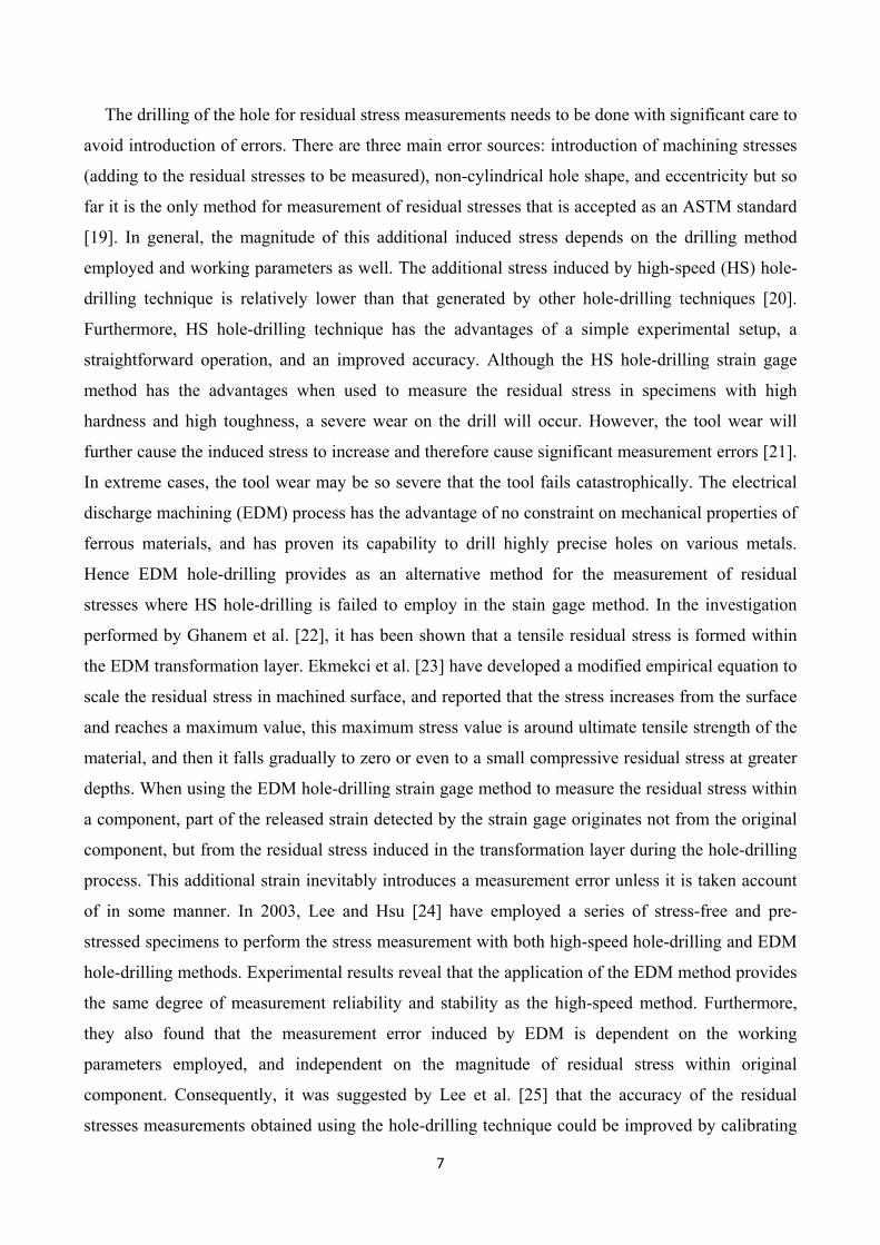
The drilling of the hole for residual stress measurements needs to be done with significant care to
avoid introduction of errors. There are three main error sources: introduction of machining stresses
(adding to the residual stresses to be measured), non-cylindrical hole shape, and eccentricity but so
far it is the only method for measurement of residual stresses that is accepted as an ASTM standard
[19]. In general, the magnitude of this additional induced stress depends on the drilling method
employed and working parameters as well. The additional stress induced by high-speed (HS) hole-
drilling technique is relatively lower than that generated by other hole-drilling techniques [20].
Furthermore, HS hole-drilling technique has the advantages of a simple experimental setup, a
straightforward operation, and an improved accuracy. Although the HS hole-drilling strain gage
method has the advantages when used to measure the residual stress in specimens with high
hardness and high toughness, a severe wear on the drill will occur. However, the tool wear will
further cause the induced stress to increase and therefore cause significant measurement errors [21].
In extreme cases, the tool wear may be so severe that the tool fails catastrophically. The electrical
discharge machining (EDM) process has the advantage of no constraint on mechanical properties of
ferrous materials, and has proven its capability to drill highly precise holes on various metals.
Hence EDM hole-drilling provides as an alternative method for the measurement of residual
stresses where HS hole-drilling is failed to employ in the stain gage method. In the investigation
performed by Ghanem et al. [22], it has been shown that a tensile residual stress is formed within
the EDM transformation layer. Ekmekci et al. [23] have developed a modified empirical equation to
scale the residual stress in machined surface, and reported that the stress increases from the surface
and reaches a maximum value, this maximum stress value is around ultimate tensile strength of the
material, and then it falls gradually to zero or even to a small compressive residual stress at greater
depths. When using the EDM hole-drilling strain gage method to measure the residual stress within
a component, part of the released strain detected by the strain gage originates not from the original
component, but from the residual stress induced in the transformation layer during the hole-drilling
process. This additional strain inevitably introduces a measurement error unless it is taken account
of in some manner. In 2003, Lee and Hsu [24] have employed a series of stress-free and pre-
stressed specimens to perform the stress measurement with both high-speed hole-drilling and EDM
hole-drilling methods. Experimental results reveal that the application of the EDM method provides
the same degree of measurement reliability and stability as the high-speed method. Furthermore,
they also found that the measurement error induced by EDM is dependent on the working
parameters employed, and independent on the magnitude of residual stress within original
component. Consequently, it was suggested by Lee et al. [25] that the accuracy of the residual
stresses measurements obtained using the hole-drilling technique could be improved by calibrating
8
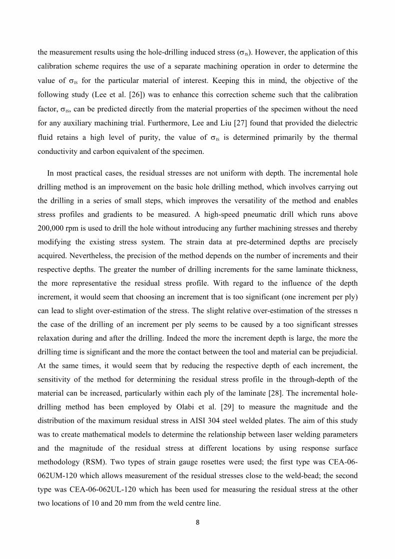
the measurement results using the hole-drilling induced stress (σIS). However, the application of this
calibration scheme requires the use of a separate machining operation in order to determine the
value of σIS for the particular material of interest. Keeping this in mind, the objective of the
following study (Lee et al. [26]) was to enhance this correction scheme such that the calibration
factor, σIS, can be predicted directly from the material properties of the specimen without the need
for any auxiliary machining trial. Furthermore, Lee and Liu [27] found that provided the dielectric
fluid retains a high level of purity, the value of σIS is determined primarily by the thermal
conductivity and carbon equivalent of the specimen.
In most practical cases, the residual stresses are not uniform with depth. The incremental hole
drilling method is an improvement on the basic hole drilling method, which involves carrying out
the drilling in a series of small steps, which improves the versatility of the method and enables
stress profiles and gradients to be measured. A high-speed pneumatic drill which runs above
200,000 rpm is used to drill the hole without introducing any further machining stresses and thereby
modifying the existing stress system. The strain data at pre-determined depths are precisely
acquired. Nevertheless, the precision of the method depends on the number of increments and their
respective depths. The greater the number of drilling increments for the same laminate thickness,
the more representative the residual stress profile. With regard to the influence of the depth
increment, it would seem that choosing an increment that is too significant (one increment per ply)
can lead to slight over-estimation of the stress. The slight relative over-estimation of the stresses n
the case of the drilling of an increment per ply seems to be caused by a too significant stresses
relaxation during and after the drilling. Indeed the more the increment depth is large, the more the
drilling time is significant and the more the contact between the tool and material can be prejudicial.
At the same times, it would seem that by reducing the respective depth of each increment, the
sensitivity of the method for determining the residual stress profile in the through-depth of the
material can be increased, particularly within each ply of the laminate [28]. The incremental hole-
drilling method has been employed by Olabi et al. [29] to measure the magnitude and the
distribution of the maximum residual stress in AISI 304 steel welded plates. The aim of this study
was to create mathematical models to determine the relationship between laser welding parameters
and the magnitude of the residual stress at different locations by using response surface
methodology (RSM). Two types of strain gauge rosettes were used; the first type was CEA-06-
062UM-120 which allows measurement of the residual stresses close to the weld-bead; the second
type was CEA-06-062UL-120 which has been used for measuring the residual stress at the other
two locations of 10 and 20 mm from the weld centre line.

9
Recent work [30, 31] has concentrated on the use of full-field optical techniques to measure the
deformations around a drilled hole. These developments have greatly expanded the scope of hole-
drilling residual stress measurements, notably by providing a very rich source of available data.
These additional data can provide detailed information about residual stress distributions, and can
enable issues such as non-linear material behaviour and non-uniform stresses to be taken into
account.
2.1.2 Deep hole method
The deep hole method [32, 33] is a further variant procedure that combines elements of both the
hole-drilling and ring-core methods. In the deep-hole method, a hole is first drilled through the
thickness of the component. The diameter of the hole is measured accurately and then a core of
material around the hole is trepanned out, relaxing the residual stresses in the core. The diameter of
the hole is re-measured allowing finally the residual stresses to be calculated from the change in
diameter of the hole. The deep hole method is classified as a semi destructive method of residual
stresses measurement since although a hole is left in the component, the diameter of the hole can be
quite small and could coincide with a hole that needs to be machined subsequently. The main
feature of the method is that it enables the measurement of deep interior stresses. The specimens
can be quite large, for example, steel and aluminum castings weighing several tons. Initial
development of the deep-hole method was carried out by Zhandanov and Gonchar [34], Beaney
[35], Jesensky and Vargova [36]. Zhadanov and Gonchar used the deep-hole method to measure
residual stresses in steel welds. They drilled 8 mm diameter holes and trepanned out a 40 mm
diameter core. In their method, the trepanning was carried out incrementally. Beaney used a 3 mm
gun-drill and an electro-chemical machining process to trepan the core. He measured the diameter
of the hole using two strain gauged beams that were drawn along the sides of the hole. His
methodology was later improved by Procter and Beaney [37] with the introduction of non-
contacting capacitance gauges to measure the hole diameter. Jesensky and Vargova [36] again
measured residual stresses in steel welds but used strain gauges attached to the sides of the hole to
measure the strain relaxation following trepanning. More recent improvements to the deep-hole
method have been made by Smith and his coworkers [38 – 41]. They have followed an approach of
gun-drilling a hole of 3 mm nominal diameter and measuring the change in diameter of the hole
using an air probe. The air probe works by calculating the clearance between the gauge and the hole
from the pressure required to blow air from the gauge into the gap. Trepanning the core is carried
out using an electro-discharge machining (EDM) operation [42 – 45].

10
The deep-hole method has become a standard technique for the measurement of residual stresses
in isotropic materials. The method is particularly suited to thick components. Some investigators
[46] have developed an extension to the method to allow the measurement of residual stress in
orthotropic materials such as thick laminated composite components.
2.1.3 Sectioning technique
Sectioning technique [47, 48] is a destructive method that relies on the measurement of
deformation due to the release of residual stress upon removal of material from the specimen. It has
been used extensively to analyze residual stresses in structural carbon steel, aluminum and stainless
steel sections [49 – 51]. The sectioning method consists in making a cut on an instrumented plate in
order to release the residual stresses that were present on the cutting line. For this, the cutting
process used should not introduce plasticity or heat, so that the original residual stress can be
measured without the influence of plasticity effects on the cutting planes’ surface. Figure 5 shows
an example of the sectioning method, where a sequence of cuts was made to evaluate the residual
stresses in an I-beam section [48].
The strains released during the cutting process are generally measured using electrical or
mechanical strain gauges. In general, the strips of material released by the sectioning process may
exhibit both axial deformation and curvature, corresponding to membrane and bending (through
thickness) residual stresses, respectively. Membrane residual stresses σm generally dominate in hot
rolled and fabricated sections whereas bending residual stresses σb are generally dominant in cold
formed sections. These two residual stress components are illustrated in Figure 6, where the
bending stresses are assumed to be linearly varying through the thickness. From this assumption it
follows that the combined membrane and bending residual stress pattern σrc is always a linear
relationship [52].
Excellent residual stresses measurement results obtained with this method are presented in the
literature, e.g. Lanciotti et al. [53], for welded stiffened aluminum structures and centre cracked
tension specimens accordingly. Cruise and Gardner [54] have been carried out an experimental
program to quantify the residual stresses in stainless steel sections from three different production
routes. Comprehensive residual stress distributions have been obtained for three hot rolled angles,
eight press braked angles and seven cold rolled box sections. In the hot rolled and press braked
sections, residual stresses were typically found to be below 20% of the material 0.2% proof stress,
though for the cold rolled box sections, whilst membrane residual stresses were relatively low,
bending residual stresses were found to be between 40% and 70% of the material 0.2% proof stress.

11
2.1.4 Contour method
The contour method, first proposed in 2000 [55], is a newly invented relaxation method that
enables a 2D residual stress map to be evaluated on a plane of interest. The contour method
provides higher spatial resolution, while the sectioning technique is easier to apply since almost no
calculations are needed. The method has found a number of applications: for example, carbon steel
Tee-join welded [56, 57], quenched and impacted thick plates [58], cold-expanded hole [43] and
aluminium alloy forging [8]. It offers improvements over conventional relaxation methods of
measuring residual stresses [59, 60]. The theory of the contour method is based on a variation of
Bueckners elastic superposition principle [61]. The method was first published in detail in 2001,
where the contour method was numerically verified by 2D finite element (FE) simulation and
experimentally validated on a bent steel beam having a known residual stress distribution [60]. The
potential of the contour method was later demonstrated on a 12-pass TIG BS4360 steel weld to
measure a complex 2D stress variation across the weld section [56]. The result obtained from the
contour method was in excellent quantitative agreement with the outcome measured by a
completely different technique non destructive neutron diffraction. A high stress component, over
the initial yield stress of the material, was measured in that case. The contour method was also
successfully used for measuring the residual stresses induced by impact in a high-strength low-alloy
steel (HSLA-100) with thickness up to 51 mm [58]. The comparison with explicit FE simulation of
the impact process indicated a good match, and the as-received HSLA-100 quenched plate showed
a typical quenching residual stress distribution. Another application was an EN8 steel plate with a
cold-expanded hole where a characteristic profile of 2D longitudinal residual stresses was measured
by the contour method [62]. The measured cold expansion stress profile was compared with the
result predicted by 3D FE modelling, and the comparison was encouraging although there were
certain errors at edges, including hole edges. The latest application of the contour method was a
7075 aluminium alloy hand forging, in which three cuts were performed in orthogonal directions to
obtain three directions of the stress tensor [59]. The measured stresses were in good agreement with
the FE-predicted outcomes.
Application of the contour method primarily involves four steps: specimen cutting, contour
measurement, data reduction and stress analysis, which will be detailed as follows.
• Weld cutting: specimen cutting is the first and the most critical step in implementing the
contour method, as the subsequent procedures of contour measurement, data reduction and
stress analysis are all reliant on the quality of the cutting. Wire electric discharge machining
12
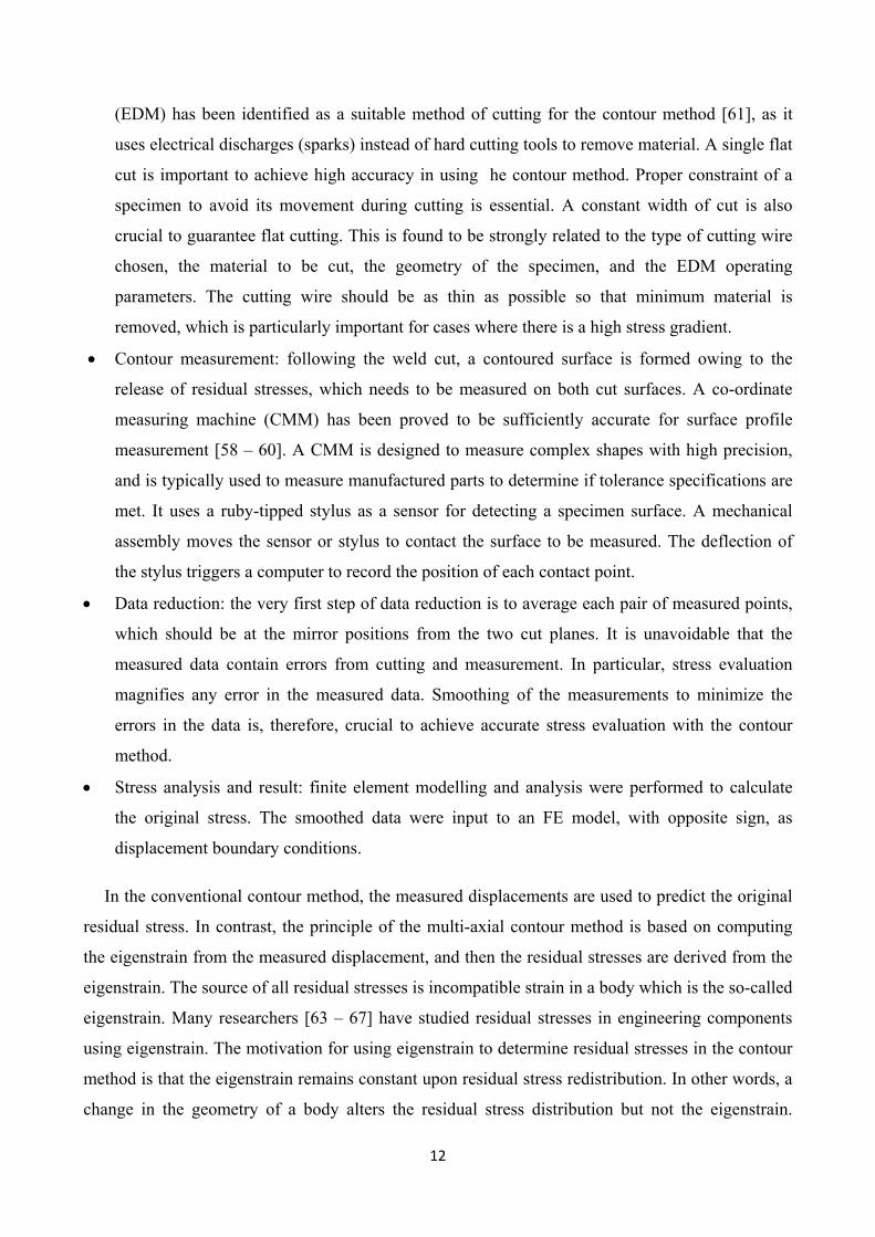
(EDM) has been identified as a suitable method of cutting for the contour method [61], as it
uses electrical discharges (sparks) instead of hard cutting tools to remove material. A single flat
cut is important to achieve high accuracy in using he contour method. Proper constraint of a
specimen to avoid its movement during cutting is essential. A constant width of cut is also
crucial to guarantee flat cutting. This is found to be strongly related to the type of cutting wire
chosen, the material to be cut, the geometry of the specimen, and the EDM operating
parameters. The cutting wire should be as thin as possible so that minimum material is
removed, which is particularly important for cases where there is a high stress gradient.
• Contour measurement: following the weld cut, a contoured surface is formed owing to the
release of residual stresses, which needs to be measured on both cut surfaces. A co-ordinate
measuring machine (CMM) has been proved to be sufficiently accurate for surface profile
measurement [58 – 60]. A CMM is designed to measure complex shapes with high precision,
and is typically used to measure manufactured parts to determine if tolerance specifications are
met. It uses a ruby-tipped stylus as a sensor for detecting a specimen surface. A mechanical
assembly moves the sensor or stylus to contact the surface to be measured. The deflection of
the stylus triggers a computer to record the position of each contact point.
• Data reduction: the very first step of data reduction is to average each pair of measured points,
which should be at the mirror positions from the two cut planes. It is unavoidable that the
measured data contain errors from cutting and measurement. In particular, stress evaluation
magnifies any error in the measured data. Smoothing of the measurements to minimize the
errors in the data is, therefore, crucial to achieve accurate stress evaluation with the contour
method.
• Stress analysis and result: finite element modelling and analysis were performed to calculate
the original stress. The smoothed data were input to an FE model, with opposite sign, as
displacement boundary conditions.
In the conventional contour method, the measured displacements are used to predict the original
residual stress. In contrast, the principle of the multi-axial contour method is based on computing
the eigenstrain from the measured displacement, and then the residual stresses are derived from the
eigenstrain. The source of all residual stresses is incompatible strain in a body which is the so-called
eigenstrain. Many researchers [63 – 67] have studied residual stresses in engineering components
using eigenstrain. The motivation for using eigenstrain to determine residual stresses in the contour
method is that the eigenstrain remains constant upon residual stress redistribution. In other words, a
change in the geometry of a body alters the residual stress distribution but not the eigenstrain.

13
Hence, multiple cuts can be made without changing the eigenstrain distribution. Moreover, as long
as the eigenstrain variation in the body is known, its residual stress can be calculated for any
configuration sectioned from this body. The multi-axial contour stress measurement technique was
applied successfully to the measurement of the residual stresses in a VPPA-welded plate [68]. The
measurements were compared with results obtained previously using neutron diffraction, and good
agreement was obtained. The method has therefore been successfully validated.
2.1.5 Other destructive methods
Other less used methods such as excision, splitting, curvature, layer removal and slitting, are
described as follows. Excision is a simple quantitative method for measuring residual stresses. It
entails attaching one or more strain gauges on the surface of the specimen, and then excising the
fragment of material attached to the strain gauge(s). This process releases the residual stresses in the
material, and leaves the material fragment stress-free. The strain gauge(s) measure the
corresponding strains. Excision is typically applied with thin plate specimens, where the cutting of a
small material fragment around the strain gauge(s) is straightforward. Application on thicker
specimens is also possible. Full excision is possible, but is not usually done because the
inconvenience of the undercutting process required to excavate the material fragment. Indeed,
partial excision by cutting deep slots at each end of the strain gauge [69 – 71] is a more practical
procedure. Figure 7(a) illustrates the splitting method [72]. A deep cut is sawn into the specimen
and the opening (or possibly the closing) of the adjacent material indicates the sign and the
approximate size of the residual stresses present. This method is widely used as a quick comparative
test for quality control during material production. The “prong” test shown in Figure 7(b) is a
variant method used for assessing stresses in dried lumber [73]. The splitting method is usually used
to assess the in residual stresses thin-walled tubes. In Figure 7 are shown two different cutting
arrangements [74], (c) for evaluating longitudinal stresses and (d) for circumferential stresses. The
latter arrangement is commonly used for heat exchanger tubes, and is specified by ASTM standard
E1928 [75]. The thin-wall tube splitting method illustrated in Figure 7(c, d) is also an example of
Stoney’s Method [76], sometimes called the curvature method. This method consists in measuring
the deflection or curvature of a thin plate caused by the addition or removal of material containing
residual stresses. The method was firstly developed for evaluating the stresses in electroplated
materials, and is also useful for assessing the stresses induced by shot-peening [77].

14
The layer removal method is a generalization of Stoney’s Method. It involves observing the
deformation caused by the removal of a sequence of layers of material. The method is suited to flat
plate and cylindrical specimens where the residual stresses are known to vary with depth from the
surface, but to be uniform parallel to the surface. Figure 8 illustrates examples of the layer removal
method, (a) on a flat plate specimen, and (b) on a cylindrical specimen. The method involves
measuring deformations on one surface, for example using strain gauges, as parallel layers of
material are removed from the opposite surface [78]. In the case of a hollow cylindrical specimen,
deformation measurements can be made on either the outside or inside surface, while annular layers
are removed from the opposite surface. If applied to cylindrical specimens, the layer removal
method is commonly called “Sachs’ Method” [79]. The method is a general one; it is typically
applied to metal specimens, e.g., but can be applied to other materials, e.g., paperboard [80].
Some investigator [81, 82] have applied this method using electrochemical machining (ECM) for
measurement of the residual stresses in a metallurgy steel. Since it is a non-mechanical metal
removal process, ECM is capable of machining any electrically-conductive material with attendant
high removal rates, regardless of mechanical properties. In particular, the removal rate in ECM is
independent of the hardness and toughness of the material being machined.
The slitting method [83 – 85] is also very similar to the hole-drilling method, but using a long slit
rather than a hole. Figure 9 illustrates the geometry. Strain gauges are attached either on the front or
back surfaces, or both, and the relieved strains are measured as the slit is incrementally increased in
depth. The slit can be introduced by a thin saw, milling cutter or wire EDM. Due to this, the
residual stresses perpendicular to the cut can then be determined from the measured strains using
finite element calculated calibration constants, in the same way as for hole-drilling calculations.
Overall, the slitting method has the advantage over the hole-drilling method that it can evaluate the
stress profile over the entire specimen depth, the surface strain gauge providing data for the near-
surface stresses, and the back strain gauge providing data for the deeper stresses. However, the
slitting method provides only the residual stresses normal to the cut surface, whereas the hole-
drilling method provides all three in-plane stresses. Additional cuts can be made to find other stress
components, in which case the overall procedure resembles the sectioning method [86 – 88]. The
slitting method can also be applied to estimate the stress intensity factor caused by residual stresses,
which is very useful for fatigue and fracture studies [89].
15
2.2 Diffraction techniques
Diffraction methods are based on determining the elastic deformation which will cause changes
in the interplanar spacing, d, from their stress free value, d0. Then, the strain could be calculated by
using Bragg’s law and of course it is necessary to have an accurate measure of stress-free
interplanar spacing. The most common diffraction methods are as follows.
2.2.1 X-ray diffraction method
The X-ray method is a non destructive technique for the measurement of residual stresses on the
surface of materials. X-ray diffraction techniques exploit the fact that when a metal is under stress,
applied or residual stress, the resulting elastic strains cause the atomic planes in the metallic crystal
structure to change their spacings. X-ray diffraction can directly measure this inter-planar atomic
spacing; from this quantity, the total stress on the metal can then be obtained [90, 91].
Since metals are composed of atoms arranged in a regular three-dimensional array to form a crystal,
most metal components of practical concern consist of many tiny crystallites (grains), randomly
oriented with respect to their crystalline arrangement and fused together to make a bulk solid. When
such a polycrystalline metal is placed under stress, elastic strains are produced in the crystal lattice
of the individual crystallites. In other words, an externally applied stress or one residual within the
material, when bellow the yield strength of the material, is taken up by inter-atomic strains in the
crystals by knowing the elastic constants of the material and assuming that stress is proportional to
strain, a reasonable assumption for most metals and alloys of practical concern [92]. Therefore, X-
ray diffraction residual stresses measurement is applicable to materials that are crystalline,
relatively fine grained, and produce diffraction for any orientation of the sample surface. Sample
may be metallic or ceramic, provided a diffraction peak of suitable intensity and free of interference
from neighboring peaks can be produced in the high back-reflection region with the radiations
available [93]. Some investigators have used the X-ray method to evaluate the residual stress
distribution in dissimilar metal welds of maraging steel to quenched and tempered medium alloy
medium carbon steel across the weldment (i.e., perpendicular to welding direction) [94] and to
measure the residual stresses on the top side of a double-electrode butt welded steel plates in
longitudinal and transversal directions [95]. Indeed, some problems arise when using diffraction to
determine the residual stresses in large welds because the limited space available on most beam
lines or X-ray diffractometers means that samples often need to be cut-down in order to be
measured. The geometry has to be such that an X-ray can both hit measurement area and still be
diffracted to the detector without hitting any obstructions. Portable diffractometers that can be taken
out into field for measurements of structures such as pipelines, welds, and bridges are now available
16
[96]. It could be also combined with some form of layer-removal technique so that a stress profile
can be generated, but then the method becomes destructive and the current results clearly indicate
that such cutting must be done with care to ensure the stress state is not unduly altered [97].
Moreover, in the case of a nanostructured material, it is not easy to use diffraction techniques
because of the difficulty involved in analyzing the shape of the nanomaterial diffraction peak. It is
difficult to pinpoint the peak location or to determine the peak shift in order to study the
macroscopic stress due to severe plastic deformation for many materials. For this reason,
mechanical methods are the only techniques known for the study of residual stresses in all kinds of
surface nanostructured materials without the effect of nanostructure [98]. The speed of
measurement depends on a number of factors, including the type of material being examined, the X-
ray source, and the degree of accuracy required. The gauge volume is a trade-off between the need
for spatial resolution within the expected strain field and the time available for data collection. With
careful selection of the X-ray source and test set-up speed of measurement can be minimized. New
detector technology has also greatly reduced the measurement time.
Third generation synchrotron sources provide access to high X-ray energies. At these high (hard)
energies the attenuation length, defined as the path length over which the intensity falls to e−1,
increases markedly. This combined with the very high X-ray intensities they produce leads to path
lengths of centimetres even in steel [99]. The main advantages are the high intensity and the high
collimation of the beam, which allow data acquisition rates of the order of seconds if not
milliseconds, and the definition of millimeter to micron size sampled gauge dimensions [100]. The
intense beams of high energy synchrotron X-rays available at synchrotron sources offer
unparalleled spatial resolution lateral to the beam (1–100 μm) and fast data acquisition times (1 ms
say). These make the method well suited to the collection of detailed maps of the strain field in two
or three dimensions, or to monitor phase transformations where neutron diffraction would be
unfeasibly slow. In counterpoint, there are serious drawbacks in the application of the synchrotron
method. Firstly, the low scattering angles mean that the sampling gauge is usually very elongated.
This means that the spatial variation is very different in different directions, being excellent lateral
to the beam, but much poorer along the beam. Secondly, the low scattering angles mean that the
method is well-suited to plate geometries where the significant stresses are in-plane, but for large or
geometrically complex samples it can be difficult to achieve short path lengths for all measurement
directions. Consequently it is often not possible to derive the stresses (which require at least 3
perpendicular strain values) without invoking simplifying assumptions, e.g. plane stress. As a
solution researchers have developed hybrid methods whereby synchrotron diffraction is used to
17
provide two components of strain and another method, e.g. neutron diffraction used to determine
the third [101]. It should also be noted that neutron diffraction is often more appropriate for
multiphase or composite materials containing both high and low atomic number elements. Finally,
in many cases the high spatial resolutions achievable in theory cannot be realised in practice
because the powder method breaks down due to insufficient grain sampling. Even at similar gauge
dimensions to the neutron method, the very low divergence of the incident X-ray beam means that
in many cases too few grains satisfy the diffraction condition to provide results representative of the
bulk [102].
2.2.2 Neutron diffraction method
Neutron diffractions method is very similar to the X-ray method as it relies on elastic
deformations within a polycrystalline material that cause changes in the spacing of the lattice planes
from their stress-free condition. The application of neutron diffraction in solving engineering
relevant problems has become widespread over the past two decades. The advantage of the neutron
diffraction methods in comparison with the X-ray technique is its lager penetration depth. In fact the
X-ray diffraction technique has limits in measuring residual stresses through the thickness of a
welded structure. On the other hand, a neutron is able to penetrate a few centimeters into the inside
of a material, thus it can be applied widely to evaluate an internal residual stress of materials. It
enables the measurement of residual stresses at near-surface depths around 0.2 mm down to bulk
measurement of up to 100mm in aluminum or 25 mm in steel [103]. This is especially useful for
alloys of high average atomic number because the penetration of X-rays falls off rapidly in this
regime. With high spatial resolution, the neutron diffraction method can provide complete three-
dimensional maps of the residual stresses in material. At each measurement point, strain was
measured in three orthogonal directions: along the sample axis (axial strain εA), transverse to it
(transverse strain εT) and through the wall (normal strain εN). This was achieved by mounting each
sample in three different orientations as shown in Figure 10 (the strain measurement direction
bisects the incident and diffracted beam directions) [104]. However, compared to other diffraction
technique such as X-ray diffraction, the relative cost of application of neutron diffraction method, is
much higher, mainly because of the equipment cost. It is too expensive to be used for routine
process quality control in engineering applications.
In 2001, after a series of round robin studies an International Organisation for Standardisation
Technology Trends Assessment document was produced recommending procedures for the
measurement of residual stress by neutron diffraction in polycrystalline materials [105]. It outlines

18
the method to be followed, calibration procedures, recommends diffraction peaks to be used for
different materials, how to deal with elastic and plastic anisotropy, methods for inferring the strain
free lattice parameter and reporting guidelines. In the past neutron diffractometers have generally
been built as “all-purpose” instruments, with designs that are compromises, balancing competing
requirements to measure the intensities, positions and widths of diffraction peaks simultaneously. In
contrast the newly constructed diffractometer ENGIN-X [106] was designed with the single aim of
making engineering strain measurements; essentially the accurate measurement of polycrystalline
lattice parameters, at a precisely determined position. Under this design philosophy, considerable
performance improvements have been obtained compared to the existing instrument. The
improvement in count times obtained allows for more complete studies, either through more
detailed scanning experiments of components, or for parametric studies. The improvement in
intensity and low background also means that larger path lengths than previously possible can now
be achieved, allowing for the study of large parts. Finally, the improved count times allow the study
of shorter timescale phenomena. Danna et al. [107] detailed the design philosophy of this
instrument, including tuneable incident resolution, together with the approaches used to realise the
performance required. The improved instrument performance was demonstrated , with results
obtained during the commissioning of ENGIN-X. These results include strain mapping
experiments, and demonstrate the influence of resolution on required count times, and provide a
direct comparison with measurements from the existing ENGIN instrument at ISIS.
There are several reports experimental about neutron diffraction measurements of weld stresses;
Martinson et al. [108] have applied the neutron diffraction technique to characterize laser and
resistance spot welds to gain an understanding of residual stresses of different joint geometries used
in the automotive industry. Paradowska [109] had used the neutron diffraction technique to
investigate and compare the residual stresses characteristics in fully restrained samples with
different numbers of beads. The aim of the research was to characterize the residual stress
distribution which arises in a welded component with increasing the number of passes or beads. The
resolution of the measurements carried out in this work achieves a new level of detail and reveals
significant features of the residual stress pattern in multi-bead welding. The findings have important
consequences for the design of welding procedures, demonstrating the effects of placing new beads
on prior welding.
Taken together with the complementary synchrotron method it can provide non destructive
evaluation for the introduction of new process technologies, or for structural integrity assessment at
the component or plant scale. Recently, neutrons have even been used to study welding process
19
induced stresses in. At the device level, neutron diffraction can provide information into the
activation of smart transformations, while at the material level it delivers phase or grain family
information for optimizing the performance of alloys and composites. With the increasing number
and performance of dedicated neutron strain measurement instruments around the world there is no
doubt that neutron diffraction will continue to make a significant contribution to basic science and
applied engineering over the coming years [110].
2.3 Other non-destructive techniques
These methods are based on measurements of electromagnetic, optical and other physical
phenomena in the residual stress zone. The common methods among this category are as follows.
2.3.1 Barkhausen noise method
The magnetic Barkhausen noise (MBN) method is of particular interest because of its potential
as a non destructive industrial tool to measure surface residual stress (SRS) and other
microstructural parameters. MBN technique is applicable to ferromagnetic materials, which are
composed of small order magnetic regions called magnetic domains. Each domain is spontaneously
magnetized along the easy axes of the crystallographic magnetization direction. However,
magnetization vectors inside the domains oriented in such a way that the total magnetization of the
material is zero except or the natural magnets. Domains are separated each other by domain walls
also called Bloch walls. There are two types of Bloch walls in a ferromagnetic material. 180° Bloch
walls have greater mobility than 90° walls so their contribution to MBN is bigger [111]. If an
external D.C. magnetic field is applied to a ferromagnetic substance, the magnetization of the
sample changes due to the domain wall movements. Domains with alignments parallel or nearly
parallel to the applied field vector expand and others annihilate during magnetization. When all of
the magnetization vectors inside the domains align themselves in the direction of the applied field
by domain wall movements the saturation occurs [6]. Grain boundaries, lattice dislocations, second
phase materials (e.g., carbides in iron) and impurities in the ferromagnetic material act as an
obstacle for the movement of domain walls. By the application of higher magnetization force
values, force on the domain wall exceed the restraining force due to pinning sites, so there is an
increase in the magnetization in small jumps, which also give rise to hysteresis. This increase can be
determined by placing an inductive coil near to the specimen being magnetized. Because of this
magnetization change an electrical pulse is induced on the coil. When all electrical pulses produced
by all domain movements added together a noise like signal called as Barkhausen Noise is
generated [6]. Figure 11 schematically shows the design of a micromagnetic sensor. A U-shaped

20
yoke is excited by a coil connected to a bipolar power-supply unit. By the orientation of the poles,
the direction of the resulting alternating magnetic field is defined and thus the corresponding stress
component can be measured. The Barkhausen noise is detected by a small air coil whereas the
tangential field strength is measured by a Hall probe. Both signals are amplified, filtered and
evaluated in the micromagnetic testing system [112].
Stewart et al. [113] have made measurements on a welded steel plate. Away from the weld the
results are consistent with the expected compressive stress parallel to the weld direction. At a point
near one edge of the weld, the amount and character of the MBN changed sharply, suggesting a
concentration of stress. MBN is sensitive to changes in applied stress. This phenomenon of elastic
properties interacting with domain structure and magnetic properties of the material is called a
"magneto-elastic interaction". As a result of magneto-elastic interaction, in materials with positive
magnetic anisotropy (iron, most steels and cobalt), compressive stresses will decrease the intensity
of Barkhausen noise while tensile stresses increase it. This fact can be exploited so that by
measuring the intensity of Barkhausen noise the amount of residual stresses can be determined. As
well as being sensitive to the stress state of ferromagnetic materials, Barkhausen noise is also
affected by the microstructural state of the material. This implies that the stress dependent
Barkhausen signal will change from one material to the next. Therefore, for MBN to be effective in
determining residual or applied stresses, different materials must be calibrated individually. Yelbay
et al. [114] in their study have concluded that calibration procedure is very important for accurate
and reliable results. Each zone having remarkably different microstructure should be separately
considered for calibration.
Previous studies [115, 116] on steels have shown that the maximum amplitude of the MBN
signal decreases with the reduction in grain size however, it increases with increasing
misorientation angles at the grain boundary. From a similar viewpoint, it is almost impossible to use
the MBN to assess residual stresses in weldments containing heat-affected zones (HAZ), since HAZ
have very rapid microstructural gradients. Jua et al. [117] have developed a modified magnetic
Barkhausen noise method to obtain the residual stress distribution in an API X65 pipeline
weldment. In order to reflect the microstructural variations in the heat-affected zone, calibration
samples were extracted from four different regions: weld metal, coarse-grained HAZ (CGHAZ),
fine-grained HAZ (FGHAZ), and base metal. This approach yielded that compressive residual
stresses existed in the CGHAZ contrary to the tensile results using the base-metal-based calibration
method. Compared with the results from the mechanical cutting method, it can be concluded that
the data obtained with the HAZ-based calibration method were more reliable.

21
The MBN method is also limited by the saturation of the MBN energy signal in either tension or
compression. When either minimum or maximum energy values arise the stress can no longer alter
the MBN energy level. This limits correlation between stress and MBN energy to maximum tensile
and maximum compressive stress values. However, this magnetic BN method has the advantages of
being rapid, suitable for the circular geometry like rings, and requiring no direct contact. Some
investigators [118] have developed BN method to evaluate surface residual stress in aeronautic
bearings, in particular in contact zones between ball or roller bearings and their raceways, with the
aim to move this method out of the laboratory and into the industrial environment.
The measurement depth depends mainly on the permeability of the material and it is typically up
to 0.2 mm for surface hardened components. Since this depth is 100 times more than that of X-ray
diffraction, the Barkhausen noise method is also capable of quantifying subsurface stress without
need of removing the surface layer.
2.3.2 Ultrasonic method
One of the promising directions in the development of non destructive techniques for residual
stresses measurement is the application of ultrasound. Ultrasonic method, called also refracted
longitudinal (LCR) wave techniques, is not limited by the types of material understudy and can be
utilized for residual stresses measurements on thick samples. Ultrasonic stress measurement
techniques are based on the acoustic-elasticity effect, according to which the velocity of elastic
wave propagation in solids is dependent on the mechanical stress [119, 120]. The most important
advantages of the development technique and equipment is the possibility to determinate the
residual and applied stresses in samples and real structure elements. The relationships between the
changes of the velocities of longitudinal ultrasonic waves and shear waves with orthogonal
polarization under the action of tensile and compressive loads in steel and aluminum alloys are
presented in Figure 12 [121]. As can be seen, the intensity and character of these changes can be
different, depending on the material properties. Different configurations of ultrasonic equipment
can be used for residual stresses measurements. Overall, waves are launched by a transmitting
transducer, propagate through a region of the material, and are detected by a receiving transducer,
as show in Figure 13 [122].
The technique in which the same transducer is used for excitation and receiving of ultrasonic
waves is often called the pulse-echo method. This method is effective for the analysis of residual
stresses in the interior of the material. In this case the trough-thickness average of the residual
stresses is measured. In the configuration shown in Figure 13 the residual stress in a (sub)surface

22
layer is determined. The depth of this layer is related to the ultrasonic wave-length, often exceeding
a few millimetres, and hence is much greater that obtained by X-ray method. Other advantages of
the ultrasonic technique are the facts that instrumentation is convenient to use, quick to step up,
portable, inexpensive, and free of radiation hazards. This method is suitable for routine inspection
procedures for large components such as steam turbine discs [123, 124].
In the technique proposed by Kudryavtsev et al. [121], the velocities of longitudinal ultrasonic
wave and shear waves with orthogonal polarization are measured at a considered point to
determinate the uni-and biaxial residual stresses. The bulk waves in this approach are used to
determine the stresses averaged over the thickness of the investigated elements. Surface waves are
used to determine the uni-and-biaxial stresses at the surface of the material. The mechanical
properties of the material are represented by the proportionality coefficients, which can be
calculated or determinate experimentally under external loading of a sample of the considered
material. They developed the ultrasonic computerized complex (UCC) that includes a measurement
unit supporting software and a laptop with an advanced database and expert system (ES) for the
analysis of the influence of residual stresses on the fatigue life of welded components. The UCC
allows the determination of uni-and biaxial applied and residual stresses for a wide range of
materials. In general, the change in the ultrasonic wave velocity in structural materials under
mechanical stress amounts to only tenths of a percentage point. Therefore the equipment for
practical application of ultrasonic technique for residual stress measurement should be of high
resolution, reliable, and fully computerized. Ya et al. [125] have used an ultrasonic method to
measure the non-uniform residual stresses in the transverse direction of the aluminum alloys.
Aluminum alloys are widely used in the automotive, aerospace and other industries because of their
high strength/weight ratio. They show that the LCR technique offers advantages not possible with
other acoustic techniques, such as acoustic birefringence. Specifically the LCR technique is less
sensitive to texture, most sensitive to stress, and is capable of indicating stress gradients.
Furthermore, the LCR technique does not require opposite parallel surfaces and, therefore, does not
impose any strict geometric limitations on the test specimens.
Currently, the main difficulty with such methods is that the relative deviations of ultrasonic
velocities produced by the presence of stress are extremely small. Time-of-flight measurements are
usually carried out to determine the velocity difference. The accuracy of such measurements
obviously depends on the time duration of a probe pulse. On the other hand the duration of a probe
pulse can’t be reduced indefinitely, because the attenuation of ultrasound in metals is usually
proportional to the second or even fourth degree of frequency. Nonetheless, a compromise can be
23
achieved with the application of wide-band ultrasonic pulses. However traditional piezoelectric
techniques are inefficient for excitation over a very wide frequency range. Karabutov et al. [126]
have developed a new laser ultrasonic method for residual stress measurements. The optoacoustic
(OA) phenomenon can be employed for producing a large frequency band. The ultrasonic transients
excited by the absorption of laser radiation in a metal follow the time envelope of the laser pulse
intensity. In this way it is possible to obtain nanosecond ultrasonic pulses with an aperiodic
temporal profile, a wide frequency spectrum, and pressure amplitudes up to a few hundreds of MPa.
3. Conclusion
The non destructive residual stresses measurement methods have the obvious advantage of
specimen preservation, and they are particularly useful for production quality control and for
measurement of valuable specimens. However, these methods commonly require detailed
calibrations on representative specimen material to give required computational data. The
diffraction methods such as X-ray and neutron diffraction can be applied for the polycrystalline and
fine grained materials as well as metallic or ceramic. However, they cannot be used for large welds
because the limited space available on most beam lines or X-ray diffractometers or for
nanostructured materials because of the difficulty involved in analyzing the shape of the
nanomaterial diffraction peak. The advantage of the neutron diffraction method in comparison with
the X-ray technique is its lager penetration depth as x-ray method is limited for the measurement of
residual stresses on the surface of materials. However, the relative cost of application of neutron
diffraction method, is much higher, mainly because of the equipment cost and it is not
recommended to be used for routine process quality control in engineering applications. The
magnetic Barkhausen noise (MBN) method is applicable to ferromagnetic materials. It is affected
by the “magneto-elastic interaction”, by the saturation of the MBN energy signal in either tension or
compression and by the microstructural state of the material, therefore different materials must be
calibrated individually. However, this magnetic BN method has the advantages of being rapid,
suitable for the circular geometry like rings, requiring no direct contact and the penetration is 100
times more than that of X-ray diffraction. Ultrasonic method, is not limited by the types of material
understudy and can be utilized for residual stresses measurements on thick samples. Although this
method is completely portable and cheap to perform, the wave’s velocities depend on
microstructural in-homogeneities and there are difficulties in separating the effects of multi-axial
stresses. This method is especially recommended for routine inspection procedures for large
components such as steam turbine discs.
24
In comparison to the non destructive method, the destructive and semi destructive residual
stresses measurement methods generally require much less specific calibrations because they
measure fundamental quantities such as displacements or strains, thus giving them a wide range of
application. The hole drilling method is a cheap, fast and popular semi destructive method. It could
be applied to isotropic and machinable materials whose elastic parameters are known. The main
problem of this method regards the introduction of machining stresses. The high-speed (HS) hole-
drilling technique allows to resolve this problem inducing a lower additional stress and it has got the
advantages of a simple experimental setup, a straightforward operation, and an improved accuracy.
HS Hole-drilling is suggested to measure the residual stresses in specimens with high hardness and
high toughness. However, the tool wear will further cause the induced stress to increase and
therefore cause significant measurement errors. EDM hole-drilling provides as an alternative
method for the measurement of residual stresses where HS hole-drilling is failed to employ in the
stain gage method. It has got the advantage of no constraint on mechanical properties of ferrous
materials, and has proven its capability to drill highly precise holes on various metals. When the
residual stresses are not uniform with depth the incremental hole-drilling method is recommended.
It needs the appropriate trade-off with regard both the number of the drilling increments and the
depth of each increment. The ring-core method is a variant of the hole drilling method suitable for
much larger surface strains but it creates much greater specimen damage and is much less
convenient to implement in practice. The semi destructive deep hole method combines elements of
both the hole-drilling and ring-core methods. It enables the measurement of deep interior stresses
for quite large specimens as steel and aluminum castings weighing several tons and it has become a
standard technique for the measurement of residual stress in isotropic materials. The sectioning
technique is a destructive method that gives only the average residual stresses for the area from
which the piece was removed but it is still counted as a simple and accurate method for
measurement in structural carbon steel, aluminum and stainless steel sections.
Many of these methods are the subject of continual advancement, but two in particular are of
particular interest for the future because they have only recently become routinely available. As
regards destructive methods, the contour method promises to be a useful complement to existing
methods, being the first destructive method to provide high-resolution maps of the stress normal to
the cut surface. However, it is not possible to make successive slices close together or at right
angles to one another in order to comprehensively map the stress tensor due to stress relaxation
caused by each successive cut. The method find a number of application for example, steel welds,
quenched and impacted thick plates, cold-expanded hole and aluminium alloy forging. By the
25
nature of the cutting process, provided one can find an electro-discharge machine big enough, the
contour method can reveal the stress fields over large areas. This makes it ideal for identifying hot-
spot locations in residual stress. As regards non destructive method, the use of synchrotron radiation
to perform strain scanning is a relatively recent development in residual stresses measurement, and
its advantages lie in favorable combination of high X-ray intensity and penetration, combined with
count times that range from several minutes per point to well under a minute, depending on the
synchrotron source and the details of the experimental set-up. It is particularly useful for relatively
thin plates of light element materials, such as aluminum alloys.
Finally, in the Table 1 are summarized the advantages and the disadvantages of each methods,
while Figure 14 shows the penetration and the spatial resolution.
Finally, the following remarks should be considered when choosing the residual stress measurement
techniques:
1- X-ray diffraction method can be used for ductile materials to obtain both macro and micro
residual stresses, but it is a lab based methods and can be used for small components.
2- Hole and deep hole drilling methods are easy and fast methods, they can be used for wide
range of materials, but they are semi destructive method and it has limited strain sensitivity
and resolution.
3- Neutron diffraction has an optimal resolution but it needs an expensive and specialist
facilities.
4- Barkhausen noise and Ultrasonic both are fast, easy and low cost methods but they have low
resolution.
5- Sectioning method is fast and can be used for a wide range of materials but it is a destructive
method and has a limited strain resolution..
6- Contour method has a high resolution and can be used to high range of materials and for
large components, but it is a destructive method.
7- Finally, Synchroton method is fast method for both macro and micro residual stresses, but it
needs a very special equipments.
26
References
[1] G. Totten. Handbook on residual stress. SEM, Bethel 2005, ISBN: 978-0871707291; 1: 417.
[2] V. Trufyakov, P. Mikheev, Y. Kudryavtsev. Fatigue Strength of Welded Structures. London: Harwood Academic 1999; p.100.
[3] E.M. Anawa, A.G. Olabi. Control of welding residual stress for dissimilar laser welded materials. Journal of materials processing technology 2008; 204: 22–33.
[4] E. Macherauch, K.H. Kloos. Origin, Measurements and Evaluation of Residual Stresses. Residual Stresses in Science and Technology 1987; pp.3–26.
[5] C. Lachmann, Th. Nitschke-Pagel, H. Wohlfahrt. Non-destructive characterization of fatigue processes in cyclically loaded welded joints by the Barkhausen noise method. Stanford University: 2nd International Workshop on Structural Health Monitoring; 1999.
[6] J. Lu. Handbook of Measurement of Residual stresses. SEM, Bethel 1996, ISBN: 978-
0132557382; 1: 319-322. [7] A.G. Olabi, M.S.J. Hashmi. Stress relief procedures for low carbon steel (1020) welded
components, Journal of Materials Processing Technology 1996; 56: 552-562. [8] F.A. Kandil, J. D. Lord. A review of residual stress measurement methods, a guide to technique
selection. NPL Report MAT(A)04, 2001. [9] K.P. Milbradt. Ring-method determination of residual stresses. Proc SESA 1951; 9(1): 63–74. [10] S. Kiel. Experimental determination of residual stresses with the ring-core method and an on-
line measuring system. Exp Tech 1992; 16(5): 17–24. [11] A. Ajovalasit, G. Petrucci, B. Zuccarello. Determination of non-uniform residual stresses using
the ring-core method. Journal of Materials Processing Technology 1996; 118(2): 224–228. [12] B. Scholtes. Residual stress analysis of components with real geometries using the incremental
hole-drilling technique and a differential evaluation method. Kassel university press GmbH 2007.
[13] Vishay measurements group, 2007 http://www.vishaypg.com/ (accessed March 1, 2011). [14] J. Liu, H. Zhu, W. Xu. Analysis of residual stresses in thick aluminum friction stir welded butt
joints. Materials and Design 2011; 32(4): 2000-2005. [15] A.G. Olabi, M.S.J. Hashmi. The effect of post-weld heat-treatment on mechanical-properties
and residual-stresses mapping in welded structural steel. Journal of Materials Processing Technology 1995; 55: 117-122.
27
[16] A.G. Olabi, M.S.J. Hashmi. Effects of the stress-relief conditions on a martensite stainless-steel welded component, Journal of Materials Processing Technology 1998; 77: 216–225.
[17] A.G. Olabi, G. Casalino, K.Y. Benyounis, A. Rotondo. Minimisation of the residual stress in
the heat affected zone by means of numerical methods. Materials and Design 2007; 28: 2295–2302.
[18] K. Y. Benyounis, A. G. Olabi, J. H. Abboud. Assessment and Minimization of the Residual
Stress in Dissimilar Laser Welding. Applied Mechanics and Materials 2007; 7-8: 139-144. [19] G.S. Schajer. Hole-Drilling Residual Stress Measurements at 75: Origins, Advances,
Opportunities. Experimental Mechanics 2009; 50: 245–253. [20] M.T. Flaman, G.A. Herring. Comparison of four hole-producing techniques for the center-hole
residual-stress measurement method. Exp. Tech. 1985; 9: 30–32. [21] M.T. Flaman, G.A. Herring. Ultra-high-speed center-hole technique for difficult machining
materials, Exp. Tech. 1986; 10: 34–35. [22] F. Ghanem, C. Braham, H. Sidhom. Influence of steel type on electrical discharge machined
surface integrity. Journal of materials processing technology. 2003; 142: 163–173. [23] B. Ekmekci, A.E. Tekkaya, A. Erden. A semi-empirical approach for residual stresses in
electric discharge machining (EDM). Int. J. Mach. Tools Manuf 2006; 46: 858–868. [24] H.T. Lee, F.C. Hsu. Feasibility evaluation of EDM hole drilling method for residual stress
measurement. Mater. Sci. Technol. 2003; 19: 1261–1265. [25] H.T. Lee, W.P. Rehbach, F.C. Hsu, T.Y. Ta, E. Hsu. The study of EDM hole-drilling method
for measuring residual stress in SKD 11 tool steel. Journal of materials processing technology. 2004; 149: 88–93.
[26] J. Mayer, F.C. Hsu. Application of EDM hole-drilling method to the measurement of residual
stress in tool and carbon steels. J Journal of materials processing technology. 2006; 128: 468–475.
[27] H.T. Lee, C. Liu. Calibration of residual stress measurements obtained from EDM hole drilling
method using physical material properties. Mater. Sci. Technol. 2008; 24: 1462–1469. [28] O. Sicot, X.L. Gong, A. Cherouat, J. Lu. Determination of residual stress in composite
laminates using the incremental hole-drilling method. Journal of Composite Materials 2003; 37: 831–844.
[29] A. G. Olabi, K. Y. Benyounis, M. S. J. Hashmi. Application of Response Surface Methodology
in Describing the Residual Stress Distribution in CO2 Laser Welding of AISI304. Strain 2007; 43(1): 37-46.
28
[30] A. Baldi. A New Analytical Approach for Hole Drilling Residual Stress Analysis by Full Field
Method. Journal of materials processing technology. 2005; 127(2): 165.
[31] G.S. Schajer, M. Steinzing. Full-field calculation of hole-drilling residual stresses from ESPI data. Exp. Mech. 2005; 45(6): 526-532.
[32] R.H. Leggatt, D.J. Smith, S.D. Smith, F. Faure. Development and experimental validation of the deep hole method for residual stress measurement. J Strain Anal 1996; 31(3): 177–186.
[33] A.T. DeWald, M.R. Hill. Improved data reduction for the deep hole method of residual stress
measurement. J Strain Anal 2003; 38(1): 65–78. [34] I.M. Zhandano, A.K. Gonchar. Determining the residual welding stresses at depth in metals.
Automatic Welding 1978; 31: 22–4. [35] E.M. Beaney. Measurement of sub-surface stress. Central Electricity Generating Board Report
Rd/B/N4325, 1978. [36] M. Jesensky, J. Vargova. Calculation and measurement of stresses in thick-walled pressure
vessels. Svaracske Spravy 1981; 4: 79–87. [37] E. Procter, E.M. Beaney. Advances in surface treatments: technology application effects. New
York: International guide book on residual stresses 1987; 14: 165–98. [38] R.H. Leggatt, D.J. Smith, S.D. Smith, F. Faure. Development and experimental validation of
the deep-hole method for residual stress measurements. Journal of Strain Analysis 1996; 31: 177–86.
[39] N.W. Bonner, D.J. Smith. Measurement of residual stresses using the deep-hole method.
Pressure Vessels and Piping 1996; 327: 53–65. [40] D. George, P.J. Bouchard, D.J. Smith. Evaluation of through wall residual stresses in stainless
steel weld repairs. Materials Science Forum 2000; 347–349: 646–51. [41] D. George, D.J. Smith. The application of the deep-hole technique for measuring residual
stresses in auto frettaged tubes. ASME PVP High Pressure Technology 2000; 406: 25–31. [42] D. George, D.J. Smith. Residual stress measurement in thick section components. Seattle: P
roceedings of the ASME pressure vessels and piping conference 2000; 410: 275–82. [43] D.J. Smith, P.J. Bouchard, D. George. Measurement and prediction of through thickness
residual stresses in thick section welds. Journal of Strain Analysis 2000; 35: 287–305.
29
[44] D. George, E. Kingston, D.J. Smith. Measurement of through-thickness stresses using small holes. Journal of Strain Analysis 2002; 37: 125–39.
[45] R.C. Wimpory, P.S. May, N.P O’Dowd, G.A. Webster, D.J. Smith, E. Kingston. Measurement
of residual stresses in T-plate weldments. Journal of Strain Analysis 2003; 38: 349–65. [46] M.G. Bateman, O.H. Miller, T.J. Palmer, C.E.P. Breen, E.J. Kingstonb, D.J. Smith, M.J.
Pavier. Measurement of residual stress in thicksection composite laminates using the deep-hole method. International Journal of Mechanical Sciences 2005; 47: 1718–1739.
[47] J.R. Shadley, E.F. Rybicki, W.S. Shealy. Application guidelines for the parting out in a
through thickness residual stress measurement procedure. Strain 1987; 23: 157–166. [48] N. Tebedge , G. Alpsten, L. Tall. Residual-stress measurement by the sectioning method. Exp
Mech 1973; 13(2): 88–96.
[49] F.M. Mazzolani. Aluminium alloy structures. 2nd ed.. E&FN Spon, An imprint of Chapman and Hal 1995, ISBN: 978-0419177708.
[50] O. Lagerqvist, A. Olsson. Residual stresses in welded I-girders made of stainless steel and structural steel. Helsinki: Proceedings of the ninth nordic steel construction conference 2001; pp. 737–744.
[51] B. Young, W.M. Lui. Behavior of Cold-formed high strength stainless steel sections. Journal of Structural Engineering, ASCE 2005; 131(11): 1738–1745.
[52] B.W. Schafer, T. Peköz. Computational modelling of cold-formed steel: Characterizing geometric imperfections and residual stresses. Journal of Constructional Steel Research 1998; 47(3): 192–210.
[53] A. Lanciotti, L. Lazzeri, C. Polese. Presentation at the Porto meeting of the European Union DaToN project 2007.
[54] R. B. Cruise, L. Gardner. Strength enhancements induced during cold forming of stainless steel sections. Journal of Constructional Steel Research 2008; 64(11): 1320-1316.
[55] M.B Prime, A.R Gonzales. Proceedings of the sixth international conference on residual stresses. Oxford, UK: IOM Communications Ltd 2000; pp. 617–624.
[56] M.B Prime, D.J. Hughes, P.J. Webster. Proceedings of 2001 SEM annual conference on
experimental and applied mechanics. Portland, OR 2001. pp. 608–611. [57] N. Murugan, R. Narayanan. Finite element simulation of residual stresses and their
measurement by contour method. Materials and Design 2009; 30(6): 2067-2071.

30
[58] M.B. Prime, R.L Martineau. Mapping residual stresses after foreign object damage using the contour method. Materials Science Forum 2002; 404– 407: 521–5216.
[59] Y. Zhang, M.E. Fitzpatrick, L. Edwards. Measurement of the residual stresses around a cold
expanded hole in an EN8 steel plate using the contour method. Materials Science Forum 2002; 404–407: 527–34.
[60] M.B. Prime. Cross-Sectional Mapping of residual stresses by measuring the surface contour after a cut. Journal of Engineering Materials and Technology 2001; 123(2): 162–168.
[61] H.F. Bueckner. The propagation of cracks and the energy of elastic deformation. Trans ASME
1958; 80: 1225–1230. [62] M.B. Prime, M.A Newborn, J.A Balog. Quenching and cold-work residual Stresses in
aluminum hand forgings: contour Method. Materials Science Forum 2003; 426– 432: 435–440. [63] A.T DeWald, M.R Hill. Multi-axial contour method for mapping residual stresses in
continuously processed bodies. Experimental Mechanics 2006; 46: 473-490. [64] Y.M. Ueda, K. Fukuda, Y.C. Kim. New measuring method of axisymmetric three-Dimensional
residual stresses using inherent strains as parameters. Journal of Engineering Materials and Technology 1986; 108(4): 328-335.
[65] Y.M Ueda, K. Fukuda. New measuring method of three-dimensional residual stresses in long
welded joints using inherent strains as parameters-Lz method. Journal of Engineering Materials and Technology 1989; 111(1): 1-8
[66] M.R. Hill. Determination of residual stress based on the estimation of eigenstrain. PhD Thesis.
USA: Stanford University; 1996. [67] A.T. DeWald. Measurement and modelling of laser peening residual stresses in geometrically
complex specimens. PhD Thesis. Davis, USA: University of California; 2005. [68] M.E. Kartal, C.D.M. Liljedahl, S. Gungor, L. Edwards, M.E. Fitzpatrick. Determination of the
profile of the complete residual stress tensor in a VPPA weld using the multi-axial contour method. Acta Materialia 2008; 56: 4417–4428.
[69] R. Gunnert. Method for measuring residual stresses and its application to a study of residual welding stresses. Stockholm: Almqvist & Wiksell 1955.
[70] J. Schwaighofer. Determination of residual stresses on the surface of structural parts.
Experimental Mechanics 1964; 4(2): 54–56.

31
[71] D. Jullien, J. Gril. Growth strain assessment at the periphery of small-diameter trees using the two-grooves method: influence of operating parameters estimated by numerical simulations. Wood Sci Technol 2008; 42(7): 551–565.
[72] H.W. Walton. Deflection methods to estimate residual stress. Handbook of residual stress and deformation of steel. ASM International 2002, ISBN: 0-87170-729-2; pp. 89–98.
[73] J. Fuller. Conditioning stress development and factors that influence the prong test. USDA
Forest Products Laboratory, Research Paper 1995; 537: 6. [74] W.M. Baldwin. Residual stresses in metals. Philadelphia: Proc. American Society for Testing
and Materials 1949; p. 49. [75] ASTM: Standard practice for estimating the approximate residual circumferential stress in
straight thin-walled tubing. Standard test method E1928-07, West Conshohocken: American Society for testing and materials; 2007.
[76] G.G. Stoney. The tension of thin metallic films deposited by electrolysis. Proc R Soc Lond
1909; 82: 172–175. [77] W. Cao, R. Fathallah, L. Castex. Correlation of Almen arc height with residual stresses in shot
peening process. Mater Sci Technol 1995; 11(9): 967–973. [78] R.G. Treuting ,W.T. Read. A mechanical determination of biaxial residual stress in sheet
materials. J Appl Phys 1951; 22(2): 130–134. [79] G. Sachs, G. Espey. The measurement of residual stresses in metal. Iron age. 1941; pp. 63–71. [80] M. Östlund, S. Östlund , L.A. Carlsson, C. Fellers. Experimental determination of residual
stresses in paperboard. Exp Mech 1985; 45(6): 493–497. [81] F. Kafkas, C. Karatas, A. Sozen, E.Arcaklioglu , S. Saritas. Determination of residual stresses
based on heat treatment conditions and densities on a hybrid (FLN2-4405) powder metallurgy steel using artificial neural network. Materials and Design 2007; 28(9): 2431–2442
[82] E.Fetullazad, H. K. Akyildiz, S. Saritas. Effects of the machining conditions on the strain
hardening and the residual stresses at the roots of screw threads. Materials and Design 2010; 31(4): 2025-2031
[83] M.B. Prime. Residual stress measurement by successive extension of a slot: the crack
compliance method. Appl Mech Rev 1999; 52(2): 75–96. [84] M. Germaud, W. Cheng, I. Finnie, M.B. Prime. The compliance method for measurement of
near surface residual stresses analytical background. J Eng Mater Technol 1994; 119(4): 550–555.
32
[85] W. Cheng, I. Finnie. Residual stress measurement and the slitting method. New York:
Springer 2007, ISBN 978-144194241. [86] M.B. Prime, M.R. Hill. Residual stress, stress relief, and in homogeneity in aluminum plate.
Scr Mater 2002; 46(1): 77–82. [87] S. Nervi S, B.A. Szabó. On the estimation of residual stresses by the crack compliance method.
Comput Methods Appl Mech Eng 2007; 196(37–40): 3577–3584. [88] Y. An, G.S. Schajer. Residual stress determination using cross-slitting and dual-axis ESPI. Exp
Mech 2010; 50(2): 169–177. [89] H.J. Schindler, W. Cheng, I. Finnie. Experimental determination of stress intensity factors due
to residual stresses. Exp Mech 1997; 37(3): 272–277. [90] J. H. Norton and D. Rosenthal: Stress measurement by x-ray diffraction. Proceedings of the
society for experimental stress analysis 1944; 1(2): 73-76. [91] J. H. Norton and D. Rosenthal. Application of the x-ray method of stress measurement to
problems involving residual stress in metals. Proceedings of the society for experimental stress analysis 1944; 1(2): 81-90.
[92] C. O. Ruud. A review of selected non-destructive methods for residual stress measurement. NDT International 1982; 15(1): 15-23
[93] P. S. Prevéy. X-ray diffraction residual stress techniques. Lambda Technologies 2006; 10: 380-392
[94] P. Venkata Ramana, G. Madhusudhan Reddy, T. Mohandas, A.V.S.S.K.S. Gupta. Microstructure and residual stress distribution of similar and dissimilar electron beam welds – Maraging steel to medium alloy medium carbon steel. Materials and Design 2010; 31(2): 749-760.
[95] S.F. Estefen, T. Gurova, X. Castello, A. Leontiev. Surface residual stress evaluation in double-electrode butt welded steel plates. Materials and Design 2010; 31(3): 1622-1627
[96] J. Lu, D. Retraint. A review of recent developments and applications in the field of X-ray diffraction for residual stress studies. J. Strain Anal. 1998; 33(2): 127-136.
[97] X. Cheng, J. Fisher, H.Prask, T. Gnauper, B. Yen, S. Roy. Residual stress modification by post-weld treatment and its beneficial effect on fatigue strength of welded structures. Int. J. Fatigue 2003; 25: 1259-1269.
33
[98] M. Ya, Y. Xing, F. Dai, K. Lu, J. Lu. Study of residual stress in surface nanostructured AISI 316L stainless steel using two mechanical methods. Surface and Coatings Technology 2003; 168(2-3): 148-155.
[99] P.J. Withers. Depth capabilities of neutron and synchrotron diffraction strain measurement instruments. I. The maximum feasible path length. Journal of Applied Crystallography 2004; 37(4): 596–606.
[100] W. Reimers, M. Broda, B. Brusch, D. Dantz, K.-D. Liss, A. Pyzalla, T. Schmackers, T. Tschentscher, J. Nondest. Eval. Evaluation of residual stresses in the bulk of materials by high energy synchrotron diffraction. Journal of Nondestructive Evaluation 1998; 17(3): 129–140.
[101] S. Ganguly, M.E. Fitzpatrick, L. Edwards. Use of neutron and synchrotron X-ray diffraction
for evaluation of residual stresses in a 2024-T351 aluminum alloy variable-polarity plasma-arc weld. Metallurgical and Materials Transactions 2006; 37(2): 411–420.
[102] P. J. Withers. Mapping residual and internal stress in materials by neutron diffraction. Comptes Rendus Physique 2007; 8(7-8): 806-820.
[103] Seok-Hoon Kim, Jong-Bum Kim, Won-Jae Lee. Numerical prediction and neutron diffraction
measurement of the residual stresses for a modified 9Cr–1Mo steel weld. Journal of Materials Processing Technology 2009; 209(8): 3905-3913.
[104] L. Claphama, K. Abdullah , J.J. Jeswiet , P.M. Wild , R. Roggec. Neutron diffraction residual
stress mapping in same gauge and differential gauge tailor-welded blanks. Journal of Materials Processing Technology 2004; 148(2): 177-185.
[105] G.A. Webster (Ed.), Polycrystalline materials - determinations of residual stresses
by neutron diffraction. ISO/TTA3 Technology Trends Assessment, Geneva 20, Switzerland, 2001.
[106] J.A. Dann, M.R. Daymond, J.A.J. James, J.R. Santisteban, L. Edwards. A new diffractometer
optimized for stress measurements. ENGIN-X Proc. ICANS XVI 2003; 1: 231–238. [107] J.A. Dann, M.R. Daymond, L. Edwards, J.A. James, J.R. Santisteban. A comparison between
Engin and Engin-X, a new diffractometer optimized for stress measurement. Physica B 2004; 350(1-3): E511-E514.
[108] P. Martinson, S. Daneshpour, M. Koçak, S. Riekehr, P. Staron. Residual stress analysis of
laser spot welding of steel sheets. Materials and Design 2009; 30(9): 3351-3359.
[109] A. Paradowska, J.W.H. Price, R. Ibrahim, T.R. Finlayson, R. Blevins, M. Ripley. Residual stress measurements by neutron diffraction in multi-bead welding. Physica B 2006; 385-386(2): 890-893.

34
[110] W. Woo, Z. Feng, X.-L. Wang, K. An, W.B. Bailey, S.A. David, C.R. Hubbard and H. Choo. Materials Science Forum 2006; 524–525: 387–392.
[111] I. Altpeter , G. Dobmann, M. Kröning, M. Rabung, S. Szielasko. Micro-magnetic evaluation
of micro residual stresses of the IInd and IIIrd order. NDT&E International 2009; 42: 283-290.
[112] W. Theiner, P Höller. Magnetische Verfahren zu Spannungsermittlung. HTM-Beiheft:
Eigenspannungen und Lastspannungen, hrsg. v. V. Hauk und E. Macherauch, Hanser 1982; pp. 156-163.
[113] D. M. Stewart, K. J. Stevens, A. B. Kaiser: Magnetic Barkhausen noise analysis of stress in
steel. Original Research Article Current Applied Physics 2004; 4(2-4): 308-311.
[114] H. Ilker Yelbay, Ibrahim Cam, C. Hakan Gur. Non-destructive determination of residual stress state in steel weldments by Magnetic Barkhausen Noise technique. NDT&E International 2010; 43: 29–33.
[115] J. Anglada-Rivera, L.R. Padovese, J. Capo-Sanchez. Magnetic Barkhausen noise and hysteresis loop in commercial carbon steel: influence of applied tensile stress and grain size. J. Magn. Magn. Mater. 2001; 231: 299–306.
[116] S. Yamaura, Y. Furuya, T. Watanabe. The effect of grain boundary microstructure on
Barkhausen noise in ferromagnetic materials. Acta Mater 2001; 49: 3019–27.
[117] Jang-Bog Ju, Jung-Suk Lee, Jae-il Jang, Woo-sik Kim, Dongil Kwon. International Journal of Pressure Vessels and Piping 2003; 80(9): 641-646.
[118] S. Desvaux, M. Duquennoy, J. Gualandri, M. Ourak. The evaluation of surface residual stress in aeronautic bearings using the Barkhausen noise effect. Original Research Article NDT & E International 2004; 37(1): 9-17.
[119] F. Balahcene, J. Lu. Study of residual stress induced in welded steel by surface longitudinal ultrasonic metho. Proceedings of SEM Annual Conference on Theoretical, Experimental and Computational Mechanics 1999; pp. 331-334.
[120] T. Leon-Salamanca D.E. Bray. Residual stress measurement in steel plates and welds using critically refracted waves. Res. Nondestructive Eval. 1996; 7(4): 169-184.
[121] Y. Kudryavtev, J. Kleiman, O. Gushcha, V. Smilenko, V. Brodovy. Ultrasonic technique and device for residual stress measurement. X Int. Congress and Exposition on Experimental and Applied Mechanics 2004; pp. 1-7.
[122] M. J. Park, H.N. Yang, D.Y. Jang, J.S Kim, T.E. Jin. Residual stress measurement on welded specimen by neutron diffraction. Journal of Materials Processing Technology 2004; 155-156: 1171-1177.
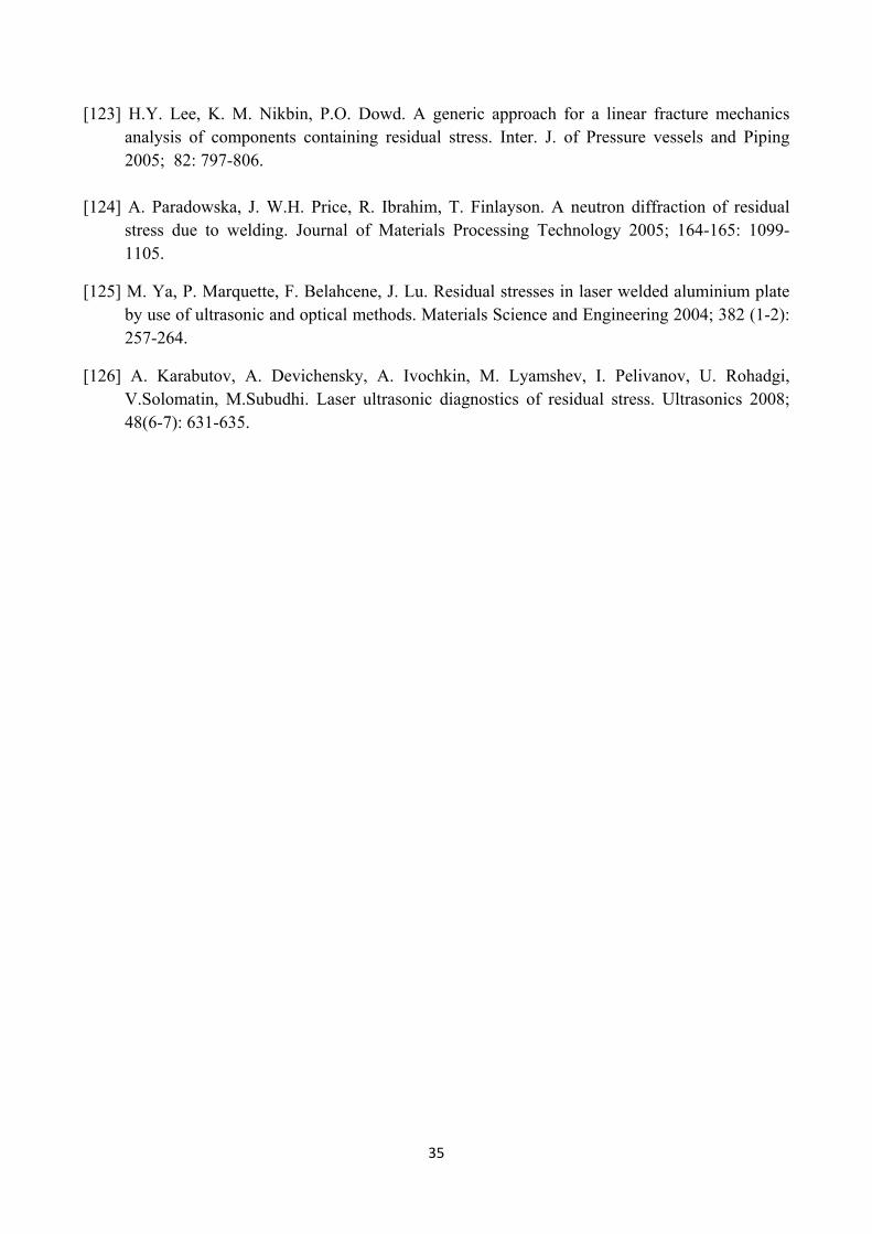
35
[123] H.Y. Lee, K. M. Nikbin, P.O. Dowd. A generic approach for a linear fracture mechanics analysis of components containing residual stress. Inter. J. of Pressure vessels and Piping 2005; 82: 797-806.
[124] A. Paradowska, J. W.H. Price, R. Ibrahim, T. Finlayson. A neutron diffraction of residual
stress due to welding. Journal of Materials Processing Technology 2005; 164-165: 1099-1105.
[125] M. Ya, P. Marquette, F. Belahcene, J. Lu. Residual stresses in laser welded aluminium plate by use of ultrasonic and optical methods. Materials Science and Engineering 2004; 382 (1-2): 257-264.
[126] A. Karabutov, A. Devichensky, A. Ivochkin, M. Lyamshev, I. Pelivanov, U. Rohadgi, V.Solomatin, M.Subudhi. Laser ultrasonic diagnostics of residual stress. Ultrasonics 2008; 48(6-7): 631-635.
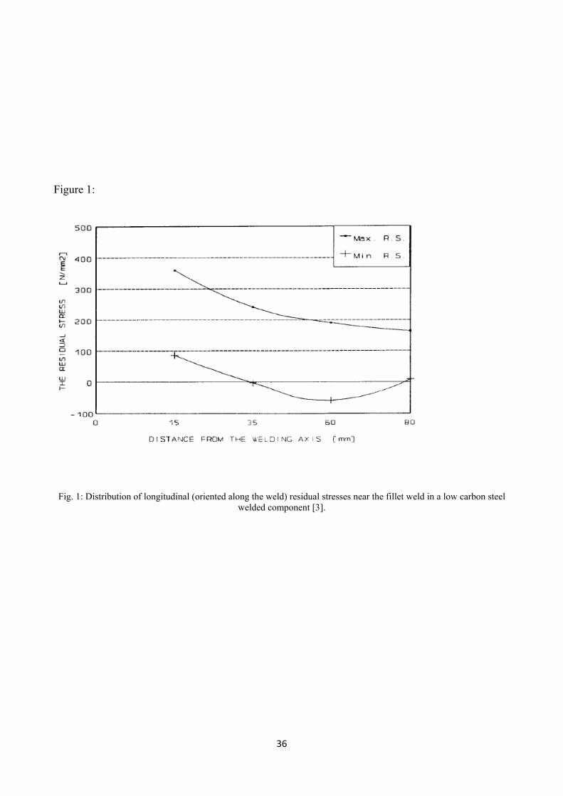
36
Figure 1:
Fig. 1: Distribution of longitudinal (oriented along the weld) residual stresses near the fillet weld in a low carbon steel welded component [3].

37
Figure 2:
Fig. 2: Change of residual stress due to metallurgical processes during welding [4].

38
Figure 3:
Fig. 3: Residual stresses measuring techniques.

39
Figure 4:
Fig. 4: Schematic illustrations of the application of hole-drilling methods for residual stress measurement [7].
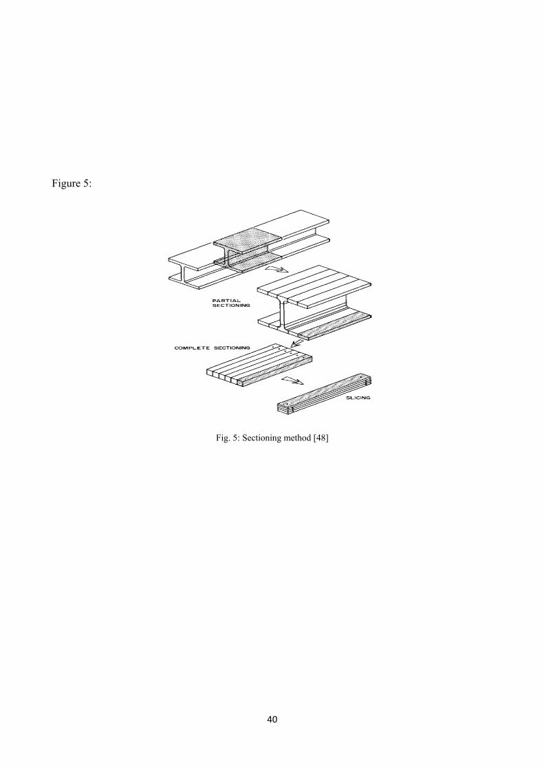
40
Figure 5:
Fig. 5: Sectioning method [48]

41
Figure 6:
Fig. 6: Modeling of residual stresses with membrane and bending stress components [54].
42
Figure 7:
Fig. 7: The splitting method, (a) for rods (from [68]), (b) for wood (from [69]), (c) for axial stresses in tubes [70], (d) for circumferential stresses in tubes [74].
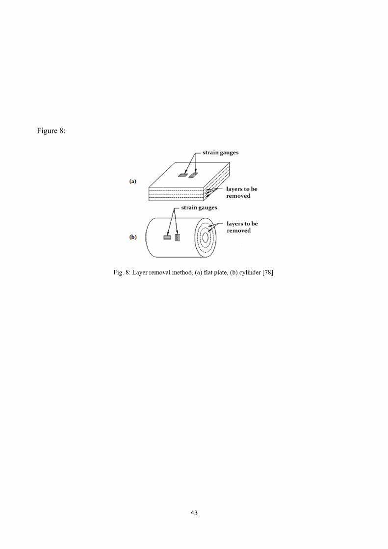
43
Figure 8:
Fig. 8: Layer removal method, (a) flat plate, (b) cylinder [78].

44
Figure 9:
Fig. 9: Slitting method [83].
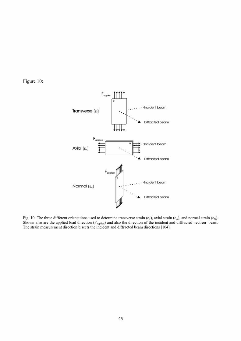
45
Figure 10:
Fig. 10: The three different orientations used to determine transverse strain (εT), axial strain (εA), and normal strain (εN). Shown also are the applied load direction (Fapplied) and also the direction of the incident and diffracted neutron beam. The strain measurement direction bisects the incident and diffracted beam directions [104].
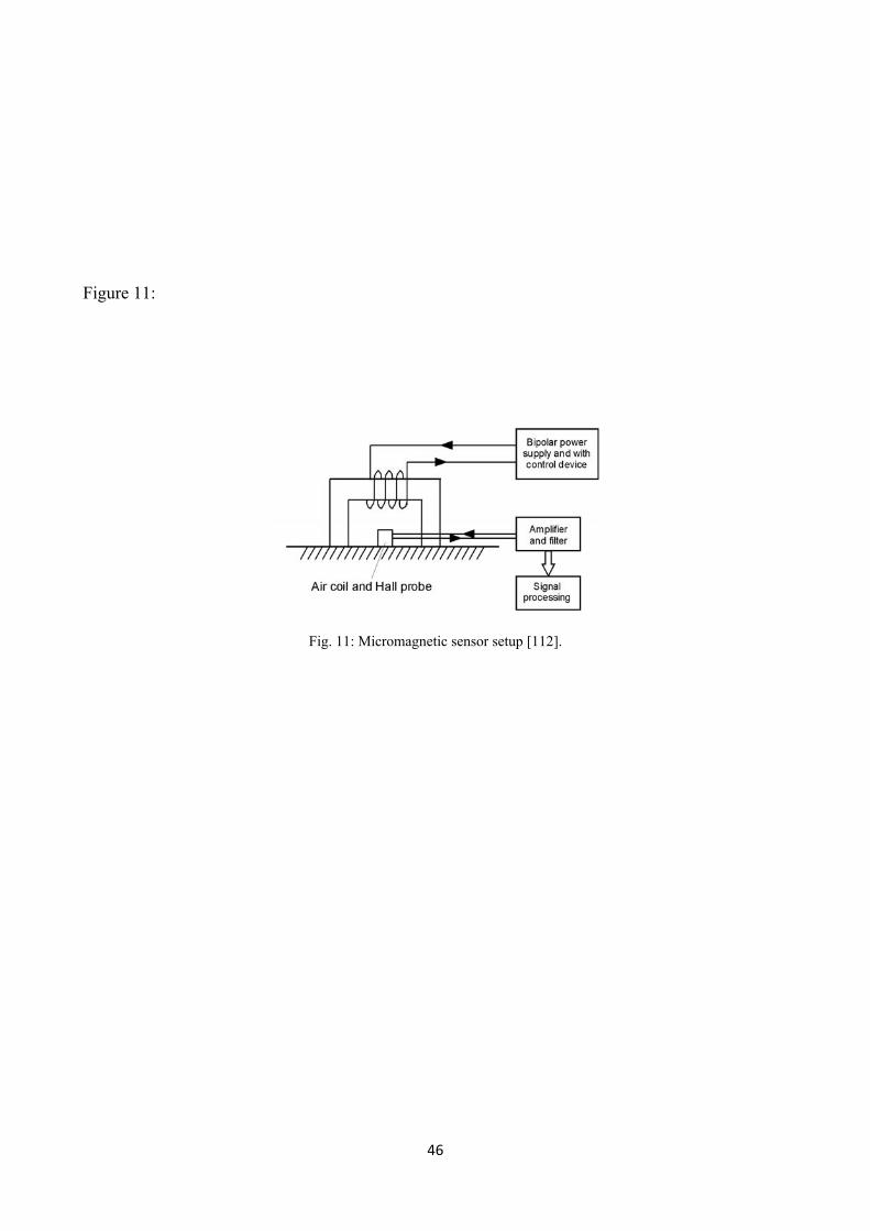
46
Figure 11:
Fig. 11: Micromagnetic sensor setup [112].

47
Figure 12:
ΔC/C ·10-3
σ, MPa
(a) (b) (c)
Fig. 12(a-c): Change of ultrasonic longitudinal wave velocity (CL) and shear waves velocities of orthogonal polarization (CSX3 ; CSX2 ) depending on the mechanical stress σ in steel A (a), steel B (b) and aluminum alloy (c): ● - CSX3 ; ○ - CSX2 ; x - CL [121].
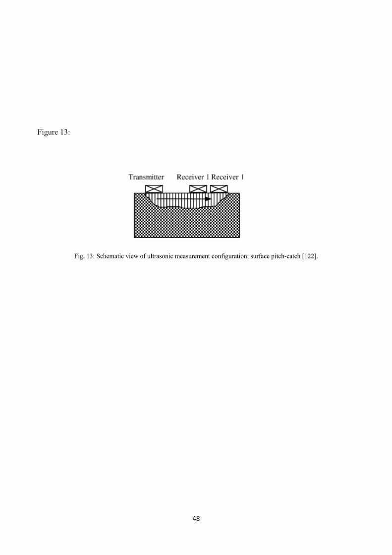
48
Figure 13:
Fig. 13: Schematic view of ultrasonic measurement configuration: surface pitch-catch [122].
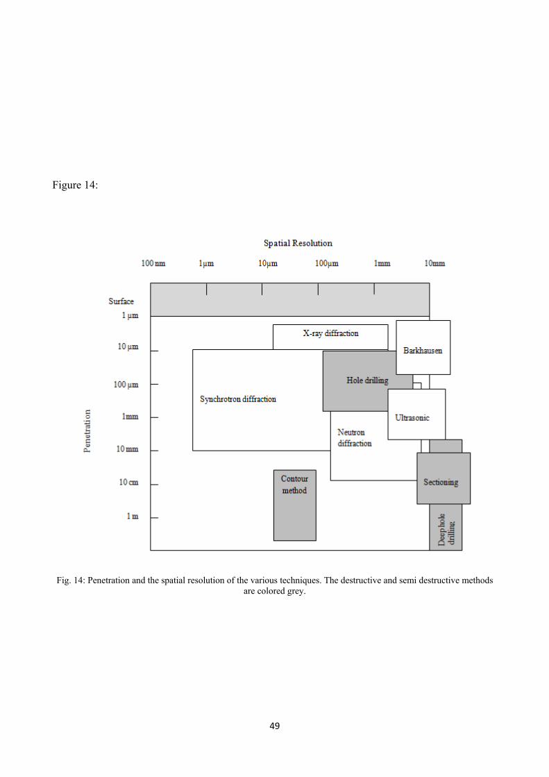
49
Figure 14:
Fig. 14: Penetration and the spatial resolution of the various techniques. The destructive and semi destructive methods are colored grey.

50
Table 1:
Table 1: Comparison of the residual stresses measurement techniques.
Technique Advantage Disadvantage
X-ray diffraction
Ductile Generally available Wide range of materials Hand-held systems Macro and Micro RS
Lab-based systems Small components Only basic measurements
Hole Drilling
Fast, Easy use Generally available Hand-held Wide range of materials
Interpretation of data Semi destructive Limited strain sensitivity and resolution
Neutron Diffraction Macro and Micro RS Optimal penetration & resolution 3D maps
Only specialist facility Lab-based system
Barkhausen Noise
Very quick Wide sensitive to Microstructure effects especially in welds Hand-held
Only ferromagnetic materials Need to divide the microstructure signal from that due to stress
Ultrasonic
Generally available Very quick Low cost Hand-held
Limited resolution Bulk measurements over whole volume
Sectioning Wide range of material Economy and speed Hand-held
Destructive Interpretation of data Limited strain resolution
Contour
High-resolution maps of the stress normal to the cut surface Hand-held Wide range of material Larger components
Destructive Interpretation of data Impossible to make successive slices close together
Deep hole drilling Deep interior stresses measurement Thick section components Wide range of material
Interpretation of data Semi destructive Limited strain sensitivity and resolution
Synchrotron
Improved penetration & resolution of X-rays Depth profiling Fast Macro and micro RS
Only specialist facility Lab-based systems