methods of mine-timbering - archive.org
TRANSCRIPT
TNC3A3
m

LIBRARYUNIVERSITY OF CAUFORJHIA
DAVIS


CAIvlKORNIA STTATTK IVIININO BURKAUJ. J. ORA"WPORt>, State Mineralogist.
BUivLKTiN No. S. San Francisco, June, 1894.
METHODS
MINE TIMBEEING.
By W. H. storms,Assistant in the Field.
SACRAMENTO:STATE OFFICE, : : : A. J. JOHNSTON, SUPT. STATE PRINTING.
1894.
LIBRARYUKIVERSITY OF CALIFORNIA
DAVIS
PREFACE.
There is no attempt in this Bulletin to present a complete treatise on
methods of mine timbering, but simply to give consideration to those
systems ordinarily used in, or adapted to, the gold mines of California.
Both in the lode and deep gravel mines of this State, those systems in
use have been selected from the best practice and applied in various
ways according to circumstances. In collecting the material herewith
presented, many mines have been visited and the details of timbering
work noted, so that those who have not an opportunity of comparing
methods for themselves may be enabled to learn the practice of others.
It has been thought proper also to give some detailed account of sys-
tems of mine timbering used in other States where extensive ore-bodies
are worked, since these are adapted to use here under corresponding
conditions.
W. H. STORMS,Assistant in the Field, State Mining Bureau.
METHODS OF MINE TIMBERING.By W. H. Storms, Assistant in the Field.
The excavation of any considerable amount of earth, or rock, beneath
the surface of the groun'd usually necessitates that the roof, and not
infrequently the sides, of such excavation be sustained artificially to
prevent caving. In these later years the size of underground excava-
tions is so great, as compared with those formerly made, that the
ingenuity and skill of the miner is taxed to the utmost limit. So suc-
cessful, however, have miners become in devising novel methods to meet
daily exigencies that the obstacles usually encountered in mining,
among which are flakey rock roofs; soft, running ground; floods of
water, sometimes scalding hot; and, worst of all, swelling ground with
heavy pressure from all sides, including the bottom, have mostly been
successfully overcome.Before Deidesheimer's " square set " system came into use, the ingen-
ious placing of posts, caps, and ^' stulls " constituted the only method of
timbering, the multitude of conditions met in the mines making the
combinations almost endless. Where veins occur in firm, solid rock,
being perpendicular, or near it, the danger of caving is greatly lessened,
and the amount of timber required is reduced to a minimum, but these
conditions are exceptional.
Veins dip at all angles between perpendicular and horizontal, andvary greatly in width. Moreover, the character of the wall rocks, as well
as of the ore itself, is so variable that unexpected problems are encoun-
tered daily. The shape of large bodies of ore is a matter of great impor-
tance in determining the system of timbering to be employed.Through all this variety and change in form, dip, size, and character
of the vein, or deposit, and in the inclosing walls, certain established
principles are followed in sustaining the roof and sides, the constant aimbeing to prevent caving, and to avoid such a catastrophe timbers are
placed with a view of holding the rock masses in place, and always in
such a manner as to receive the strain directly. Those timbers whichreach from wall to wall of an inclined vein (stulls) are not set at a
right angle to the pitch of the hanging wall, but at a somewhat higher
angle. The reason is obvious, for, if placed at a right angle, should a
subsidence of the wall occur, the timber, partaking of this movement,at its upper end, would then have a tendency to fall of its own weight,
whereas, if set originally above an angle of 90 degrees with the hangingwall, the subsidence of that wall only serves to wedge and hold the
timber support more firmly, when it must bend and break before falling.
When properly placed, stull timbers usually give sufiicient warning of
their weakness to permit of placing additional timbers and subsequentlythe removal and replacement of old or weak timbers.
To make an understanding of the various practices more comprehen-sive a number of drawings have been introduced in this article. As a
matter of course certain exigencies are likely to arise, the character of
— 6 —which has not been anticipated, but in all cases the principles appliedremain the same, and it is thought that the conditions most likely to
occur have been treated fully enough to meet the demands of metallifer-
ous mining generally.
KINDS OF TIMBER USED.
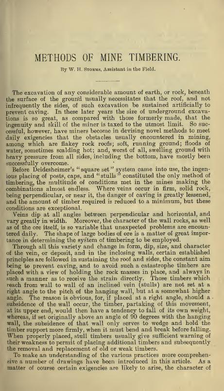
In some instances solid masonry is built to sustain certain portions of
mines, and in late years iron has been introduced as a substitute for
timber, but in American mines timber is most commonly employed.Ordinarily the location of the mine determines the kind of timber. Pineof various kinds is more extensively used than any other. Sugar pineand spruce are preferred when obtainable, but yellow pine is by far the
most common. Oak is gladly taken when good sticks of sufficient size
can be found. There are oak timbers in mines in Mariposa County,apparently sound, that have been in place for twenty years. They cer-
tainly outlast any other timber. Cottonwood and redwood are some-times used when no other is obtainable, but are not at all desirable. Inthe desert in this State, in parts of Arizona and Nevada, miners takeany timber they can get, even resorting to the yucca, which answersquite well for a time in that dry climate, when the pressure is not toogreat. At Silver Reef, in San Bernardino County, green yuccas wereused in timbering a drift. They still stand in fair condition, havingbeen in place five years. The Superintendent of the Gover Mine,Amador County, California, has commenced some experiments withspruce and sugar pine, placing them side by side in the same set in thelower levels of his mine, to test their durability.
Fig. A.
TUNNELS AND DRIFTS.
The methods employed to sustain the roof and sides of tunnels and•drifts are numerous, the existing conditions determining the method.Often the rock is sufficiently firm to stand without timber, but at times
the conditions are annoying and dangerous.
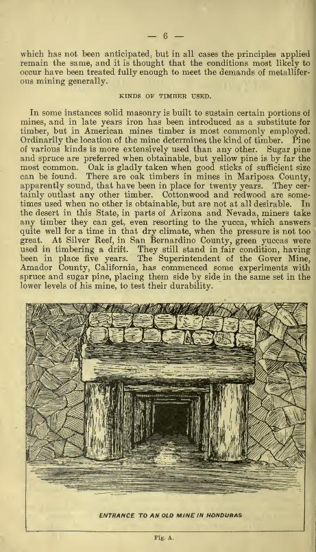
Where the pressure is entirely overhead an upright post is set oneither side of the tunnel, usually spread somewhat at the bottom, butotherwise always at right angles to the roof. (Drifts are frequently runon an incline, particularly in blanket veins, and also in fissures havinga low angle of dip.) (See Figs. 2 and 4.) On these posts are placed a
cross-piece called a cap.
"When it may occur that the floor of a tunnel, drift, or cross-cut does
not afford a firm foundation for the posts, as in soft, wet fissures, whennot in ore, or as is often the case at the entrance to a mine, a cross-piece
I I I I A- i « I tt I I I—
r
ENTRANCE TO TUNNCL, CALAVERA* COWSOLIOATTO MINE,
CARBON HILL, CALAVERAS CO^ CAL-
or sill is first laid and the posts set upon it. A second cross-piece (the
cap) is then inserted at the top, the ends resting upon the posts, the capbeing employed in all cases whether the sill is necessary or not.
In working ground that is fairly firm, particularly in the drift gravelmines of California, a system of posts and "breasting caps" is used.
This consists of a piece of timber, hewn or split, 2^ feet long, 1 foot wide,and 3 or 4 inches in thickness (the cap), which is placed against theroof, and a post of the necessary length is set beneath it, being driveninto a perpendicular position by blows of a heavy hammer or maul. It
is a cheap and secure method of timbering small drifts, and is often
employed in large ones, the breast extending entirely across the channel.Lagging placed at right angles to the cap may be driven in above it whennecessary.
— 8 —
K^^i '[\
11'
I?'
s
P

9 —
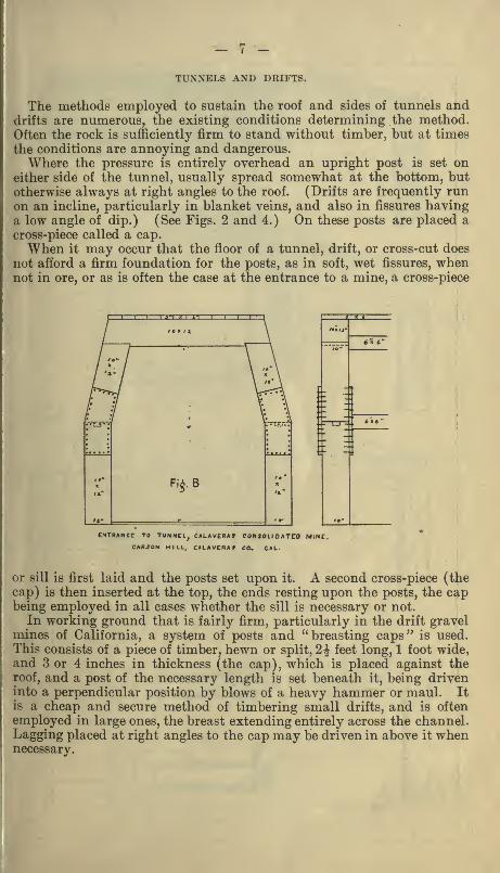
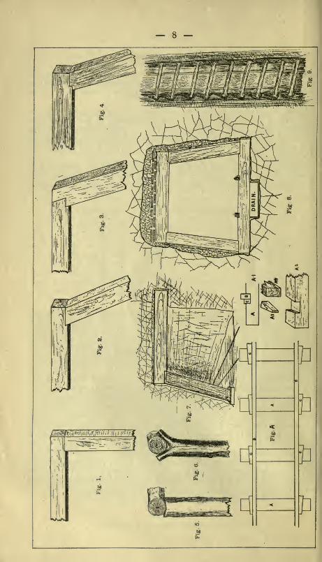
Very often pressure is exerted from the sides as well as from the top
of a drift. In such cases the timbers are framed with a view to bindingthem more firmly together when in place. (Fig. 8.)
Figs. 1, 2, 3, and 4 show several styles
of framing timbers for drifts. Of these
Fig. 4 is undoubtedly the best. Better
than any of these is the beveled notch,
which greatly reduces the liability of the
timbers splitting. It has come quite
extensively into use of late years. Whenproperly framed and set there is little
danger of slipping. Still another, and nodoubt the best method of all, has lately
come into practice. It is that of nailing
a 2-inch plank on the under side of the
cap. By this device the fullest strength
of the timbers is obtained, with no proba-bility of splitting.
THE BEVELLED NOTCH
Fig. 9 A.
• When round timbers are used they should always be stripped of thebark or they will speedily decay. The manner of framing timbers is thesame, whether they be round, hewn, or sawed.
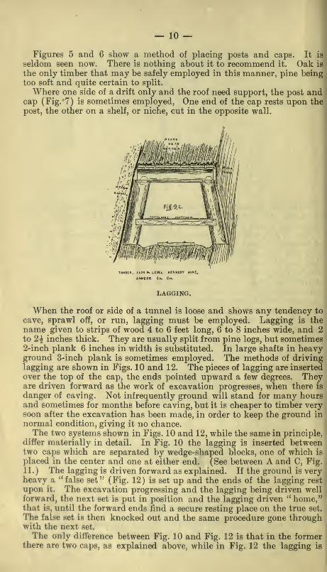
— 10 —Figures 5 and 6 show a method of placing posts and caps. It is
seldom seen now. There is nothing about it to recommend it. Oak is
the only timber that may be safely employed in this manner, pine beingtoo soft and quite certain to split.
Where one side of a drift only and the roof need support, the post andcap (Fig. 7) is sometimes employed, One end of the cap rests upon thepost, the other on a shelf, or niche, cut in the opposite wall.
USa ft. LEVCl
AMADOR Co,
LAGGING.
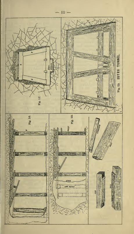
When the roof or side of a tunnel is loose and shows any tendency to
cave, sprawl off, or run, lagging must be employed. Lagging is the
name given to strips of wood 4 to 6 feet long, 6 to 8 inches wide, and 2
to 2i inches thick. They are usually split from pine logs, but sometimes2-inch plank 6 inches in width is substituted. In large shafts in heavyground 3-inch plank is sometimes employed. The methods of drivinglagging are shown in Figs. 10 and 12. The pieces of lagging are inserted
over the top of the cap, the ends pointed upward a few degrees. Theyare driven forward as the work of excavation progresses, when there is
danger of caving. Not infrequently ground will stand for many hoursand sometimes for months before caving, but it is cheaper to timber verysoon after the excavation has been made, in order to keep the ground in
normal condition, giving it no chance.The two systems shown in Figs. 10 and 12, while the same in principle,
differ materially in detail. In Fig. 10 the lagging is inserted betweentwo caps which are separated by wedge-shaped blocks, one of which is
placed in the center and one at either end. (See between A and C, Fig.
11.) The lagging is driven forward as explained. If the ground is veryheavy a '* false set" (Fig. 12) is set up and the ends of the lagging rest
upon it. The excavation progressing and the lagging being driven wellforward, the next set is put in position and the lagging driven '' home,"that is, until the forward ends find a secure resting place on the true set.
The false set is then knocked out and the same procedure gone throughwith the next set.
The only difference between Fig. 10 and Fig. 12 is that in the formerthere are two caps, as explained above, while in Fig. 12 the lagging is
— 11 —
— 12 —inserted beneath the forward ends of the next set back. In each case
the lagging is kept pointed slightly upward by the insertion of a block
of wood shown at B, Fig. 12. When the forward ends of the lagging
rest on the false set this block may be allowed to drop out. The system
shown in Fig. 10 can be employed much more advantageously and workprogress more rapidly in very heavy ground, than when that shown in
Fig. 12 is used, which does very well in lighter ground. Where the
ground is very bad the lagging must be kept driven as far forward as
possible. By observing care in this matter serious runs are sometimes
prevented. Sills are only employed when the bottom of the tunnel does
not afford a firm foundation for the posts.
For lagging, spruce, yellow pine, and tamarack are much used, but
the sugar pine of California has no superior for toughness and durability.
Lagging should not be too strong, for in the event of extreme weight
it should bend and give notice of impending danger. The miner maythen relieve the pressure by cutting away a portion and reinforcing the
timbers, thus saving the more expensive framed timbers and perhaps
preventing a serious cave.
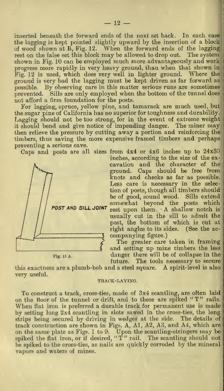
Caps and posts are all sizes from 4x4 or 4x6 inches up to 24x30inches, according to the size of the ex-
cavation and the character of the
ground. Caps should be free fromknots and checks as far as possible.
Less care is necessary in the selec-
tion of posts, though all timbers should
be of good, sound wood. Sills extendsomewhat beyond the posts which
POST AND SILL JOINT ^^^^ ^^^^ ^^^^^^ A shallow notch is
usually cut in the sill to admit the
post, the bottom of which is cut at
right angles to its sides. (See the ac-
companying figure.)
The greater care taken in framingand setting up mine timbers the less
Fig. 13 A. danger there will be of collapse in the
future. The tools necessary to secure
this exactness are a plumb-bob and a steel square. A spirit-level is also
very useful.
TRACK-LAYING.
To construct a track, cross-ties, made of 3x4 scantling, are often laid
on the floor of the tunnel or drift, and to these are spiked "T" rails.
When flat iron is preferred a durable track for permanent use is madeby setting long 2x4 scantling in slots sawed in the cross-ties, the long
strips being secured by driving in wedges at the side. The details of
track construction are shown in Figs. A, Al, A2, A8, and A4, which are
on the same plate as Figs. 1 to 9. Upon the scantling-stringers may be
spiked the flat iron, or if desired, " T '' rail. The scantling should not
be spiked to the cross-ties, as nails are quickly corroded by the mineral
vapors and waters of mines.
— 13
DRAINAGE.
I
Provision for drainage should always be made at the very commence-ment of opening a mine, for, though the tunnel may be dry at its mouth,
when it has been driven a long way into the mountain more or less water
is nearly always encountered. A drain or trench should always be cut
in the center or at the sides of every tunnel or drift. Illy drained work-
ings cause the timbers to rot quickly, and also endanger the health of
the miners. Neglect to provide drainage very often results in the neces-
sity of retimbering, which expense might otherwise have been avoided
for a long time.
Prospectors, in their haste to advance work as speedily and as cheaply
as possible, frequently fail to timber properly and to provide for drainage,
with disastrous results in the future. Many months of laborious toil are
too often lost in this way, to say nothing of the loss of life and limb bythe unfortunate miner caught in a cave which might have been easily
avoided.SWELLING GROUND.
One of the greatest difficulties with which miners have to contend is
the swelling of the rock masses into which their excavations have pene-
trated. Often the force or pressure against timbers caused by the swell-
ing of the ground is irresistible. It is a common feature of many of the
Mother Lode mines in California, particularly in Tuolumne, Calaveras,
and Amador Counties. Swelling bedrock is quite common in the gravel
drift mines of California. All Comstock miners know what swelling
ground is. It is one of the most serious obstacles with which they haveto contend.
In a general way it may be said that the only recourse is to timber in
the most substantial manner, and then, by frequently, or as often as
necessary, cutting out a portion of the heavy ground and relieving the
pressure the timbers may be kept in place and the excavation kept open.
Fig. 14 represents a cross-section of a tunnel where this trouble in its
worst form was encountered. By setting timbers in the manner shownin the cut, placing the sets close together, and relieving the ground bythe removal of the encroaching portion from time to time, the trouble is
reduced to a minimum. In the Hardenburg Mine, Amador County,swelling ground has caused a great deal of trouble lately. The 900-foot
level is run in a zone of crushed foliated black slate, which, on the foot-
wall side of the drift, when first broken, appears firm and solid, but in
a few days it commences to spawl off and to noticeably encroach uponthe drift. It continues to swell, displacing timbers or breaking them,and causing no end of trouble. Now such places are timbered with 18and 20-inch round timber and somewhat loosely lagged. But few dayspass before it is necessary to take out lagging and cut away the swelledground.
In running the main tunnel of the Hidden Treasure Mine at ForestHill, in Placer County, swelling bedrock was encountered. Mr. Ross E.Browne, E.M., in his article, " The ancient river beds of the Forest Hill
Divide" {vide X report, State Mineralogist of California), says of this
occurrence:" The pressure of the gravel is not great, but the swelling bedrock has
been a source of trouble, driving the legs of the timber-set inward and

— 14 —
crushing the cap. After many unsuccessful attempts to overcome this
difficulty, the legs were given an increasingly greater bottom spread,
until finally it was found that they remained stationary. The swelling
bedrock is removed from time to time and the track adjusted. Theaccompanying cut shows the form of tunnel timber-set now used in badswelling ground. Sets are first put in 4 feet apart, and in the course
of a few months center-sets are placed between these. Timber-sets onthis plan have now been in place three years (1879), and are still in
good condition. In 8,500 feet length of tunnel there are about 4,000 sets
of timbers. Two men are kept constantly employed in easing andrepairing the sets and adjusting the track."
Fig. 14.
^ ^ LOOSE '^ORAVEl.y
3'6"
€::>
C3-.o/
O
'I J SWetUNG 0£D'/?OC/C^f 1^ //ilfl /
./
Some of the drift mines on Sugar Loaf Mountain, near Nevada City,
Cal., that were worked twenty-five years ago, were timbered in a verypeculiar and unusual manner, owing to the swelling of the bedrock.
Massive timbers had been placed time and again, only to be forced out
of place, or broken. At last the method here described was introduced
and found to answer every requirement most admirably. It was subse-
quently tried in some of the other mines of the neighborhood withequally satisfactory results. Once firmly placed, the timbers were never
|
again renewed, standing until the mine was worked out.
The plan adopted was as follows: A drift of the usual form was runand heavily timbered, being well lagged overhead. The sets wereplaced 5 feet from center to center. As the work of excavating thei
drift proceeded, a triangular section was cut out of each side of the drift|
between the posts of the two adjoining sets. These two posts formed the
base of a triangle, the apex being directly opposite the center of the base.
At the apex a post was set, the center of which was 3 feet from the
center line of the posts forming the base. Caps were placed reachingfrom the post at the apex to each of those of the base, and lagging
driven in diagonally from the drift. The two sides of the triangular
section opposite the base were lagged, a considerable space being left
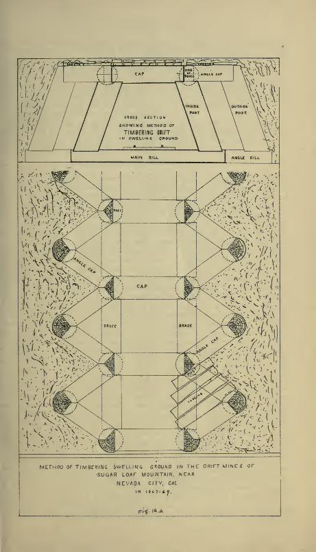
METHOD OF T/MBrRlNa SWFLLIMG GROUND IN THE DRITT MINES Of
•SUQAR LOAF MOUiNTAIN, NEAR
NEVAQA CITY, CAL
Ft?'- '4-.
A


between the lagging to atibrd an opportunity for the soft swelling ground
to force its way through the open spaces, when it is removed. These
triangular spaces were continuous; that is, were cut opposite each set of
the main drift. The method involved considerable extra expense in
mining and timbering, but it was so infinitely superior to any plan pre-
viously tried that it was looked upon as a success mechanically andfinancially. The accompanying sketch will make plain the details of
this peculiar method which since its use in the mines on Sugar Loaf
Mountain, seems to have been lost sight of.
Drifts sometimes require but a few posts to support particular rock
masses that threaten to fall. Where a post alone affords insufficient
support, a heavy piece of plank (plate) is inserted between the top of
the post and the roof.
RUNNING GROUND.
Tunnels and shafts at times must pass through soft, running ground.
Zones of rock of this description are often found lying between walls of
firmer rock. The occurrence is not infrequent on the Mother Lode of
California when the fissure is barren of quartz and filled with a mass of
soft crushed foliated black slate. It is prominent in the Quaker City,
Gwin, Hardenburg, Kennedy, and many other mines on the lode.
Such ground is nearly always wet, and the process of sinking or drift-
ing in it is attended with expense and danger. In sinking through such
ground the miners usually make an effort to push the work and pass
through it as quickly as possible. When the ground is very wet andruns easily it is not always the best plan to " crowd " it. In some cases
the difficulties are more easily overcome, the expense reduced, and the
completion of the task sooner accomplished by going slowly, allowing
the ground to assume a more normal condition by cutting out andremoving the material falling into or forced into the excavation. Whenwater is troublesome in ground of this character, the better plan is to
permit it to drain off. By so doing the ground sometimes becomes
firmer, and, as a consequence, is more easily handled, timbers morereadily placed in position, and the work carried on more satisfactorily.
Another kind of ground difficult to timber is found in some muchaltered rocks where talc, steatite (soapstone), and serpentine, containing
i
much water, have to be passed through. The ground often breaks well
and sometimes stands well for a time, but it is treacherous and should
be promptly and substantially timbered. Rocks of this description are
abundant in the great auriferous belt of California, and as miners there
well know, are usually fissured in every direction and upon exposure to
the atmosphere exhibit a tendency to break up (called blocky ground).
I
Great angular blocks and " heads " (round bowlders) drop from the roof
and sides without warning. The former are often wedge-shaped andslip out from the fissured rocks when the ground had appeared firm andsolid. The heads are usually hard in the center, while the outer portion
is quite soft, feeling greasy to the touch. In size these masses range
from an inch or two in diameter to those which weigh tons. Timbermust be placed in ground like this immediately as the work progresses.
The sets should not be more than 2^ feet from center to center, instead
of the usual distance, 4 to 5 feet, whether it be in shaft or tunnel. Lag-ging, when used, must also be short.
When passing through slips or fissures, whether single or in zones, in

— 16 —any kind of rock, extraordinary precautions should be taken, as accidentis much more likely to occur at such points than in solid, unfissuredground. Rock in the vicinity of veins is nearly always more dangerousthan that at a distance from the vein.
SHAFTS.
Working shafts, as well as tunnels and drifts, should be arrangedwith a view to securing their permanency. Indeed, in consideration of
future possibilities, even greater care should be exercised in the selection
of their location and in deciding upon their size, while the manner of
timbering is most important. Worldng shafts should be so equipped as
to remain open and be in use as long as ore remains in the mine whichit will pay to extract. As in all other mine work, the amount of timberrequired depends largely on the size of the shaft and more particularly
on the character of the rock through which it passes. Prospecting shafts
are sometimes sunk in good-standing ground to the depth of several
hundred feet without other timber than a few stulls, to which ladders
are secured. The few timbers thus placed often become insecure throughneglect, particularly in regions where there are climatic alternations of
wet and dry. When wet, the timbers and the wedges securing them,swell. With the change to dryness they shrink and are likely to dropout. An additional danger results when the rock walls crumble, andmen working below are in constant danger from falling rocks and tim-bers. The wedges demand frequent attention, for they must be keptdriven well in at all times. On the desert and in mines above timberline, where timber is expensive, miners endeavor to get along with as
little as possible and are not very particular as to the kind and quality
of that which is used. It would perhaps be a better plan to dispense
with timber altogether than to place too much dependence on sticks that
are likely to drop out of position unexpectedly. As a matter of fact,
the writer has seen shafts in the Mojave Desert mines more than 200feet in depth without a single stick of timber. The necessities of the
case in sparsely timbered regions and on the desert have obliged the
miner to resort to many novel plans to protect himself against dangerat the least possible expense. He puts in as substantial a frame of
timbers as he can obtain, or as he may think he can afford, using a fewfrail saplings, thin, split lagging, or even brush, to support the sides of
his shaft. Fortunately for him, in the desert regions, where scarcity of
timber forces upon him this economical '' system " of timbering, the rock,
being nearly always dry, stands fairly well, as a rule, and expensivetimbering is not necessary.
The extremities to which prospectors are often reduced to procure
timber in these timberless regions has resulted in the adoption of a
method peculiar to such districts. While the result is not particularly
pleasing from a workmanlike standpoint, it nevertheless exemplifies mostfaithfully those principles which are the foundation of the most elabo-
rate system of timbering. In these shafts all timbers are stulls, each onebeing placed to support some particular rock or mass which seeminglythreatens to fall. Each stick is independent of the others; there are nosuperfluous timbers, and no attempt at system or regularity. As a result
— 17 —
these sticks cross the shaft at many angles. Some are horizontal, butmost of them inclined somewhat from that position. It sometimes gives
the shaft timbers a spiral appearance as viewed from above. Despitethe fact that these timbers are placed so much at variance with recog-
nized methods, if placed at the time of making the excavation, or shortly
thereafter, and are properly and firmly wedged, they usually render theshaft fairly safe. In that region old redwood railroad ties are very fre-
quently used for mine timbers, and answer admirably, even thoughunsuited for such use from having lain for months in a railroad bed,
being split and often cut by the rails. The miners are glad to get them,poor as the timber is, for when once properly placed they have been foundto do very well, where the pressure js not too great.
Shafts having a single compartment, such as are frequently seen in
small mines, are timbered in a simple manner. The timbers consist of
two wall and two end plates and four posts to each set. The methodshown in Fig. 14 C is quite common and suited to shafts of moderate size
(5x7 in the clear), having a single compartment. The four frame timbersare placed in position and tightly wedged, the posts being driven in at
the corners. Care must be taken to keep the sets in line. Sets are
ordinarily 5 feet apart from center to center. When the ground is heavy,sets may be placed closer than 5 feet. They are often only half thatdistance from center to center.
Lagging, either split or sawed (2-inch plank), is driven in behindthe timbers. It is driven one half to three quarters of the way down,when the lower ends of the next set below are inserted between thetimber and the wall. Later the lagging of the set above is drivendown to its proper place.
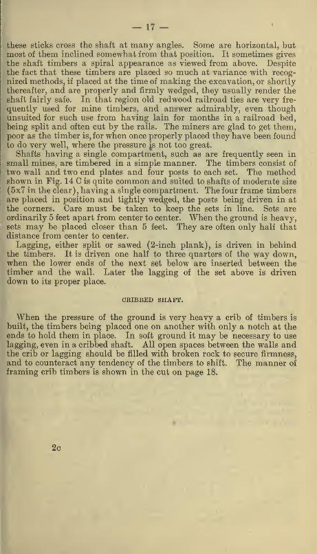
CRIBBED SHAFT.
When the pressure of the ground is very heavy a crib of timbers is
built, the timbers being placed one on another with only a notch at theends to hold them in place. In soft ground it may be necessary to uselagging, even in a cribbed shaft. All open spaces between the walls andthe crib or lagging should be filled with broken rock to secure firmness,
and to counteract any tendency of the timbers to shift. The manner of
framing crib timbers is shown in the cut on page 18.
2c
— 18 —
Fig. 14 B.
REACHERS IN SHAFTS.
When sinking can be carried on somewhat in advance of timbering, it
is sometimes the custom, in firm ground, to place long timbers, called" reachers," across the shaft, the ends resting in niches cut in the walls.
These having been firmly placed, the four timbers of the set are laid
upon them and firmly wedged, and from this foundation the sets are
built upward to the next set of reachers above, a distance of 25 to 30feet. Where the shaft is sunk in country rock, or in a large pillar of
ore (the latter to be avoided when possible), the reachers are placedalternately in sets at right angles.
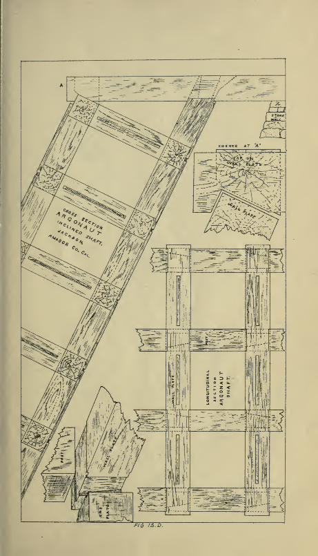
The manner of framing the ends of shaft timbers where they join at
the corners is shown in the cuts of the Requa, Forman, and Almashafts and the Argonaut incline.
Men working in shafts placing timbers usually work suspended onslings secured to timbers above.

— 19 —
fl—:-]! - ^ JLa^ft^...^^.=..^«^^^fe^ht>/WJ.^^tJ^
^Mmmr--^irn^iU"\\ ^^M\mMl -.^^ I :,tK>^a.;.4fc ^^P^#-%J( 3^ W'^^^ir^
Fig. 14 C.
IRON DOGS AND BOLTS.
In places where the above described methods of building sets of shaft
timbers on reachers is not possible, owing to the soft nature of the rock
in which the shaft is sunk, or where it is desirable to run cages to the
bottom of the mine, it was formerly the custom to suspend the shaft
timbers by ropes in a position as near to that desired as possible, andto then maintain them in that position by driving iron dogs into the
timbers, the weight being supported by the set next above, which hadpreviously been secured by wedges. In some cases these dogs were never
removed. Many of them may be seen in the older California mines.
The dogs were made of round or square iron bars 1x1 inch or 1x1^
inches, and having the ends turned at right angles. The points were
3 or 4 inches in length and sharp. The length of the dog was deter-
mined by the distance from center to center of the sets.
When the rock was sufficiently firm to admit of the timbers being
firmly wedged the dogs were knocked out. Iron dogs or bolts are useless
as a means of support when the surrounding rock masses have once
firmly settled on the timbers.
A safer and more convenient device has been introduced in later years,
in the form of iron bars having a thread at one end and a ring or hookat the other. These go in pairs, their combined length exceeding by 6
inches the distance from the top of one set to the bottom of the next set
beneath. The manner of using these hangers is as follows: A set havingbeen securely wedged in its proper position, the threaded end of the bolt
provided with a hook is passed upward through a hole in the plate
(bored in all timbers for the purpose), a washer passed over the end of
the bolt, and a threaded nut screwed down onto it. A second '' lock-
nut " may be used, but is not necessary. A second similar bolt with
— 20 —hook is passed through a hole near the opposite end of the same timber,
and also secured with washer and nut. The timber to be placed directly
below is suspended by ropes in a position approximating that desired
and a bolt having a ring at one end is passed downward through this
timber, immediately below that in the timber above, and a similar bolt
is passed through the opposite end. Washers and nuts are placed onthe* ends of these bolts and the rings are caught in the hooks of the bolts
above. The nuts may now be turned and the timber drawn to exactlythe position required, when the ropes may be removed. All four of the
timbers of this set having been placed in position, and being suspendedon the hangers, the posts are slipped in, the nuts tightened still further,
and the whole firmly wedged, when the next set below may be put in in
like manner. The hangers are left a few days or weeks, and in someinstances permanently, but, as previously stated, they are useless as a
means of support when the weight of the surrounding rock has settled
on the timbers.
Where, owing to the soft nature of the ground, it is thought desirable
to have the hangers remain in place indefinitely, a bar having a threadat one end and simply turned at a right angle at the other, or having a
solid hammered head with a washer, may be used, being passed upwardthrough the bottom timber and then through that above, where the
adjustment is made by means of a washer and nut; but as these bars
are longer than the distance between sets, their removal is impossible,
a set below once having been put in place. There is no question as to
the superiority of the bolts having rings and hooks for either temporaryor permanent use.
RETIMBERING SHAFTS.
It very frequently occurs that shaft timbers have to be removed andnew ones inserted, and also often necessary to reinforce timbers already
in place. This work frequently necessitates the suspension of hoisting
through the shaft. The Superintendent of the Wildman Mine, at Sutter
Creek, Amador County, California, having occasion to retimber the shaft
between the 500 and 600 levels of the mine, constructed a chute 1 foot
square of 2-inch plank in one corner of a compartment of the shaft
reaching between these levels. It was built in short sections, each the
length of a set of timbers. The work of retimbering was commencedabove and carried downward, all of the refuse rock, timber, etc., beingdumped into the chute. This material was taken up on the 600 level,
dumped into a skip from time to time, and sent to the surface; by this
means the work was quickly and safely carried on, sections of the chutebeing removed to keep pace with the work. By means of this device
there was very little delay in operating the skips, and hoisting of ore
was continued almost without interruption during the retimbering of
that portion of the shaft.
SHAFTS HAVING TWO OR MORE COMPARTMENTS.
Lafge shafts are separated into two or more compartments by placing
timbers called " dividers " at intermediate points between the end plates.
They reach from the wall plate on one side to that on the opposite side
of the shaft. These dividers are framed with a short beveled tenon,
broader at the top than at the bottom. (See cuts of Forman, Requa,

— 21 —
lER or rRAMIN & DIVIDER
and Alma shafts.) These tenons fit exactly into mortices or notches in
the wall plates. At each of the four corners of the shaft and between
the wall plates, opposite each divider, is placed a post, which is set in a
shallow notch or seat cut in the plates. In size the posts may equal
that of the plates, or if desired they may be of smaller dimensions. Thedividers are made the same depth as the wall plates, but are usually
narrower across the upper face.
The dividers separating shafts into two or more compartments may be
made most secure by permitting the upper portion of the beveled tenon
to extend into the wall plate 2 or 3 inches, the bottom portion being let
in but 1 inch. The post setting directly on the divider holds it muchmore firmly, and the danger of having the dividers knocked out by shots
fired directly blow is greatly decreased, if not obviated entirely. It not
infrequently occurs when dividers are framed so as to set but 1 inch into
the wall plates a heavy blast will tear them out altogether, incurring
expense of timber and time, which may be avoided in the manner stated
above.
Drawings of two Comstock shafts illustrate the manner of framingand placing timbers in them. One of these is called an " L" shaft, andwas sunk by the Overman and Caledonia companies jointly. It is
known as the Forman shaft. The other is the Requa shaft, sunk bythe Chollar, Norcross, and Savage companies. It is a large rectangular
shaft having four compartments, and is a splendid example of its kind.
An illustration of the new Alma shaft at Jackson, Amador County,California, shows a different style of framing. In fact, the manner of
framing and joining the timbers of these three shafts is totally different.
In size, shaft timbers range from 8x8 to 20x24, and even larger dimen-sions are sometimes employed in very heavy ground, particularly in
inclined shafts. The wall plates are usually broader on one side thanon the other, and are placed in position with broad side up. End plates
are usually the square of the smaller dimension of the wall plate.
Pumping and manway compartments do not require lining, but hoist-
ing compartments, particularly where cages are run, should be lined
throughout to prevent accident to men who sometimes overcrowd a cage.
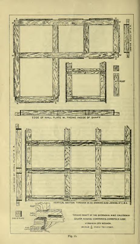
EDGE OF WALL PLATE W. FACING INSIDE OF SHAFT
'ORMAN SHAFT OF THE OVERMAN ANO CALEDONIA
3r SILVER MIMNG COMPANIES COMSTOCK LODE
VIRGINIA CITY NEVADA
SCALE A INCH TO 1 FOOT.
Fig. 10.
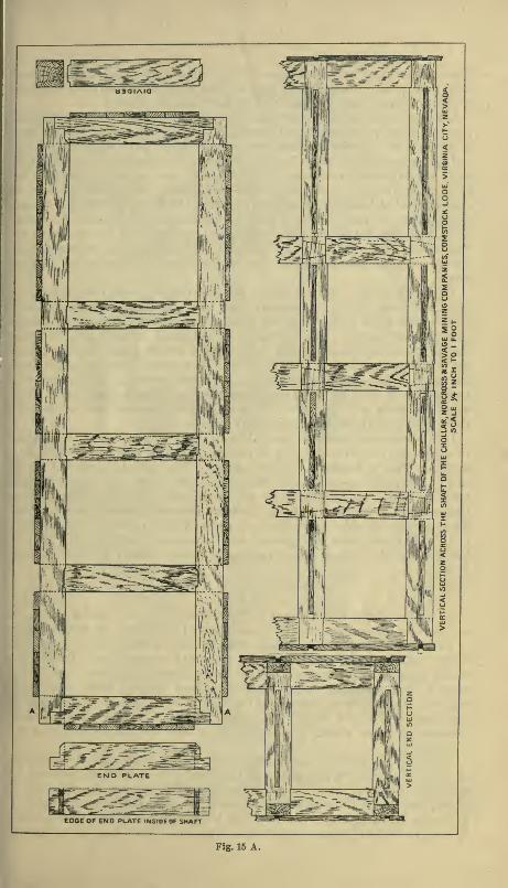
EDGE OF END PLATE INStOEOF SHAFT
Fig. 15 A.

— 24 —There appears to be less danger of this where buckets or skips are used.
Every shaft in a mine should be provided with ladder ways as a meansof exit in case of accident to shaft or hoisting machinery.
Sinking large shafts in swelling ground, in loose, watery, runningground, or in quicksand greatly multiplies the difficulties and dangersof the miner. There are instances where shafts have been abandonedowing to insurmountable obstacles which a combination of engineeringskill, capital, and labor were unable to overcome, but such instances are
of rare occurrence. Few shafts present greater difficulties than wereencountered at Leadville, Colorado; in the Lake Superior region; in somecoal mines; on the Comstock, and in Calaveras and Amador Counties,
California (the latter are mostly inclines), and some of the shafts in the
regions mentioned are to-day splendid and substantial monuments to
American engineering and to the enterprise of the companies owningthem.The shaft of El Capitan Mine, Nevada County, now the property of
the Providence Mining Company, was sunk through decomposed slate
and altered dyke rock under the most trying and dangerous conditions.
After several failures, the shaft was carried down to solid ground underthe direction of Francis Burns, who worked slowly and carefully, givingthe soft running ground time to drain. The water being pumped fromthe sump, after standing for a time, appeared to drain the ground, andit was found that by this means progress was much more rapid thanwhen the work was hurried. " Breast-boards " were carried down until
the dangerous places had been safely passed.
It is sometimes necessary in sinking large shafts to carry them downin sections by driving lagging or planks down in advance of the exca-vation. This is known as '' fore-poling.'^ The section is started at oneend of the main opening and advanced several feet, the lagging beingwell braced. Considerable water will drain into this depression, makingthe removal of the ground from the remainder of the shaft much easier.
By carrying one side of the shaft somewhat in advance of the remainder,in this manner, loose, wet ground can be worked more quickly and at
less expense than when it is attempted to carry down the entire shaft at
once.
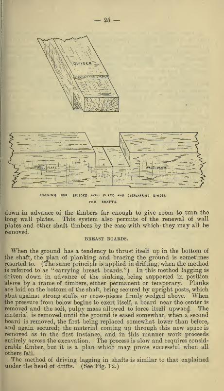
SPLICED WALL PLATES.
In cases where sinking cannot be carried on in shafts much in
advance of timbering the wall plates may be spliced. The better planis to extend the plate from one side entirely across the two hoistingcompartments, that portion in the pumping compartment being in asingle piece, and joining the longer piece directly opposite the dividernext to the pumping compartment. These joining ends of the twosections of wall plate should be framed so as to permit the divider to
lap over their entire width, the upper half of the plate sections beingremoved so as to admit the upper half of the divider, as shown in theillustration.
The post standing immediately upon the divider, and covering theentire splice and overlap, prevents the divider from being blown out byheavy shots below. This plan also greatly facilitates the placing of
shaft timbers, as there is not that great loss of time in getting the wallplates in position, which results when long timbers are handled. Thereis always difficulty and loss of time where the shaft cannot be carried


25 —
'-jj^^^^^ATp^-*2 ^=-\ ' T;rq^., .,"~n
—
. _-^ iWAtJF-; PjyrrrL- :-.^_____=^
rn/NMiNC POR SPLICED WALL Plate: and ovcrlapp.inc divider.
FOR SHArrs.
down in advance of the timbers far enough to give room to turn the
long wall plates. This system also permits of the renewal of wall
plates and other shaft timbers by the ease with which they may all beremoved.
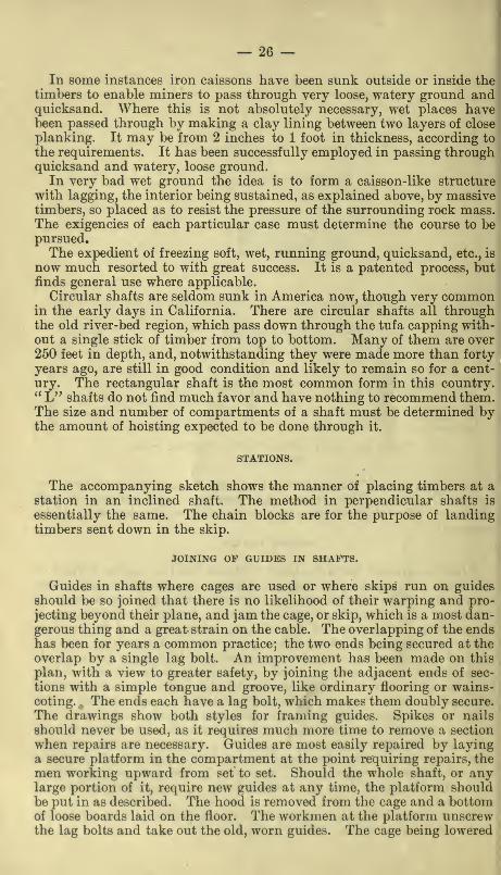
BREAST BOARDS.
When the ground has a tendency to thrust itself up in the bottom of
the shaft, the plan of planking and bracing the ground is sometimesresorted to. (The same principle is applied in drifting, when the methodis referred to as "carrying breast boards.") In this method lagging is
driven down in advance of the sinking, being supported in position
above by a frame of timbers, either permanent or temporary. Planksare laid on the bottom of the shaft, being secured by upright posts, whichabut against strong stulls or cross-pieces firmly wedged above. Whenthe pressure from below begins to exert itself, a board near the center is
removed and the soft, pulpy mass allowed to force itself upward. Thematerial is removed until the ground is eased somewhat, when a secondboard is removed, the first being replaced somewhat lower than before,
and again secured; the material coming up through this new space is
removed as in the first instance, and in this manner work proceedsentirely across the excavation. The process is slow and requires consid-
erable timber, but it is a plan which may prove successful when all
others fail.
The method of driving lagging in shafts is similar to that explainedunder the head of drifts. (See Fig. 12.)
— 26 —In some instances iron caissons have been sunk outside or inside the
timbers to enable miners to pass through very loose, watery ground andquicksand. Where this is not absolutely necessary, wet places havebeen passed through by making a clay lining between two layers of close
planking. It may be from 2 inches to 1 foot in thickness, according to
the requirements. It has been successfully employed in passing throughquicksand and watery, loose ground.
In very bad wet ground the idea is to form a caisson-like structure
with lagging, the interior being sustained, as explained above, by massivetimbers, so placed as to resist the pressure of the surrounding rock mass.The exigencies of each particular case must determine the course to bepursued.The expedient of freezing soft, wet, running ground, quicksand, etc., is
now much resorted to with great success. It is a patented process, butfinds general use where applicable.
Circular shafts are seldom sunk in America now, though very commonin the early days in California. There are circular shafts all throughthe old river-bed region, which pass down through the tufa capping with-out a single stick of timber from top to bottom. Many of them are over250 feet in depth, and, notwithstanding they were made more than forty
years ago, are still in good condition and likely to remain so for a cent-
ury. The rectangular shaft is the most common form in this country." L" shafts do not find much favor and have nothing to recommend them.The size and number of compartments of a shaft must be determined bythe amount of hoisting expected to be done through it.
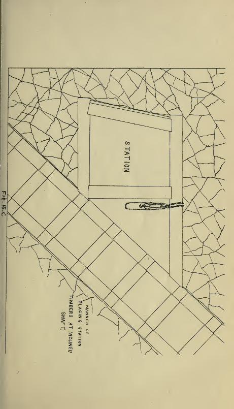
STATIONS.
The accompanying sketch shows the manner of placing timbers at astation in an inclined shaft. The method in perpendicular shafts is
essentially the same. The chain blocks are for the purpose of landingtimbers sent down in the skip.
JOINING OF GUIDES IN SHAFTS.
Guides in shafts where cages are used or where skips run on guides
should be so joined that there is no likelihood of their warping and pro-
jecting beyond their plane, and jam the cage, or skip, which is a most dan-gerous thing and a great strain on the cable. The overlapping of the endshas been for years a common practice; the two ends being secured at the
overlap by a single lag bolt. An improvement has been made on this
plan, with a view to greater safety, by joining the adjacent ends of sec-
tions with a simple tongue and groove, like ordinary flooring or wains-coting. , The ends each have a lag bolt, which makes them doubly secure.
The drawings show both styles for framing guides. Spikes or nails
should never be used, as it requires much more time to remove a section
when repairs are necessary. Guides are most easily repaired by layinga secure platform in the compartment at the point requiring repairs, the
men working upward from set to set. Should the whole shaft, or anylarge portion of it, require new guides at any time, the platform shouldbe put in as described. The hood is removed from the cage and a bottomof loose boards laid on the floor. The workmen at the platform unscrewthe lag bolts and take out the old, worn guides. The cage being lowered


I
1
CrUlOE
'M liI
'ii(,'///'/
^
r,X,X
I
II
Jl i
1'
. I
•-qrq^:yA\;^^.'
-^'>^ v/
is.
QU»DEMANNER OF FRAMlfx/G AND
SECURING GU/DETS.
p
FJQ fS.D.

— 27 —1
to the proper point, the old guides are passejd up through a hole madein the bottom of the cage, and the new guides passed down in the samemanner and put in place. In this way the guides may be removed for
a thousand feet in a single day by a gang of good workmen. Otherrepairs in the shaft may be made in a somewhat similar manner.
INCLINES.
Inclined shafts are somewhat different from those that are vertical,
and are probably quite as numerous. In California the number of
inclined shafts far exceeds those that are vertical, being, as a rule, sunkon the vein, which, in a majority of cases, dips at some angle from thehorizontal. In a general way what has been said of vertical shafts
applies to those that are inclined. There is considerable dilference, how-ever, in the manner of framing timbers for an incline, and while timbersframed for an incline will do, perhaps, equally well in a vertical shaft,
those framed as already shown in the illustration are not preferred in anincline. An illustration of the method of framing timbers for the newArgonaut shaft at Jackson, Amador County, California, which is expectedto reach a depth of 2,000 feet on the incline (63°), is given. It resemblessomewhat the new Alma shaft, also at Jackson, though the first 400 or
600 feet of the Alma will be vertical.
STOPES AND CHAMBERS.
The cuttings in mines which require the most care and greatest skill
in placing timbers to support overhanging ground are " stopes " andlarge " chambers." The method adopted must always depend upon thesize of the excavation, character of the ore and of the walls, the pitch
of the vein or ore shoot, and also on the expense of the timber.
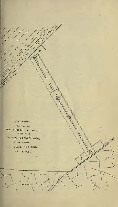
TAKING ANGLES AND DISTANCE BETWEEN WALLS.
A very convenient instrument for measuring the distance between thehanging and foot walls of the vein, and to determine their respective
angles of inclination, for the purpose of cutting stulls with proper lengthand bevels, is shown in the accompanying illustration. It consists of
two flat planed boards having slots, as shown in the drawing, and fitted
with thumb screws, s s s. At either end is a movable arm, A A. Theseare placed against the walls and the screws tightened, the distance
between walls being ascertained by lengthening or shortening the instru-
ment by means of the sliding arrangement. Having carefully taken therequired measurements, there can be no mistake as to the kind of stull
required.
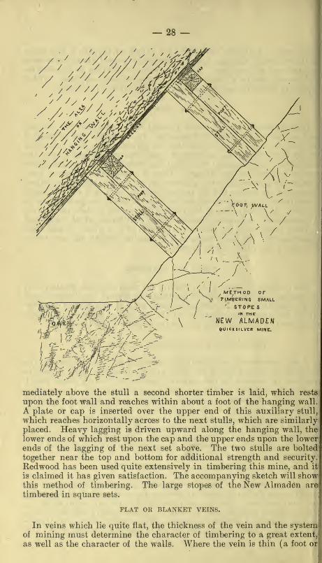
TIMBERING A SOFT HANGING WALL.
In some portions of the New Almaden Quicksilver Mine, where thewidth of ore stoped is about 10 feet, an unusual method of timberinghas been adopted. The foot wall is usually hard and solid, while the" alta," as the hanging wall is called, is almost always soft and shelly,
and is considered dangerous ground. Heavy stulls are placed at regu-lar distances (about 8 feet), and are set in line one above another. Im-
— 28
»^>^^;;''" /
^ METH 00 orTIM^eRING SMALL
STORESIN THC
NEW ALMADENQUICKSILVER MINC.
¥-MMu^^-'^n$'Mij:n^r.y.
mediately above the stull a second shorter timber is laid, which rests
upon the foot wall and reaches within about a foot of the hanging wall.
A plate or cap is inserted over the upper end of this auxiliary stull,
which reaches horizontally across to the next stulls, which are similarly
placed. Heavy lagging is driven upward along the hanging wall, the
lower ends of which rest upon the cap and the upper ends upon the lowerends of the lagging of the next set above. The two stulls are bolted
together near the top and bottom for additional strength and security.
Redwood has been used quite extensively in timbering this mine, and it
is claimed it has given satisfaction. The accompanying sketch will showthis method of timbering. The large stopes of the New Almaden are
timbered in square sets.
FLAT OR BLANKET VEINS.
In veins which lie quite flat, the thickness of the vein and the systemof mining must determine the character of timbering to a great extent,
as well as the character of the walls. Where the vein is thin (a foot or

— 29 —two) very little timber is required, the waste rock filling the entire spac8behind the miner. Where the mineral deposit is thicker and timber is
necessary various methods are pursued. Some ground stands well bysimply leaving pillars of mineral. In other cases a series of uprightposts and breasting caps will sustain the roof, the posts being placed in
rows directly back of the workmen and as close to the face as the neces-
sity demands. The foot of the post rests either directly on the rockfloor or upon a block of wood or piece of heavy plank. The posts are
forced into position by driving them up with heavy hammers. Caremust be taken that these posts are so placed as to receive the weight of
the roof directly and not at an angle. These timbers are set in lines
standing in two, three, or four rows back from the face, the waste beingpiled behind as the work advances. In this manner, by exercising care,
many sticks can be recovered before the weight settles so heavily on therefuse rock as to render it impossible to remove the timbers. Some fiat
veins make little or no waste. It is then necessary to follow the " pillar
and stall " system of extraction, considerable blocks being left to sustain
the roof. Posts and caps are used in this system also. Frequently thecaps reach in a continuous line from post to post, joining the next set,
the ends of two caps resting on a single post, the combined sets being a
hundred feet or more in width. Large timbers thus placed will supportgreat weight, but if small rocks fall from the roof lagging must also beemployed. This system is much in use in California gravel drift mines.When a vein lying nearly, or quite horizontal, and making no waste,
is to be mined, a drift should be run along the lowest portion of thedeposit, this point having been reached by incline or shaft. The workadvances toward the surface, good sized pillars being left to sustain theroof. If timber is necessary, it is put in place in the manner required.
The work having advanced sufficiently far toward the surface, the pillars
may now be cut out at the back end, while the work progresses as before.
As the pillars are removed more timber must be put in, or waste fromthe surface must be piled in cribs of timber built in the workings alreadymade. Usually some timber can be recovered in this way and thecaving of the roof after the complete removal of the ore, or mineral, doesno harm. The main gangways should be substantially timbered, if
necessary, as it is desirable to keep it open to the lowest working level
at all times.
The ''long wall" system of extracting ore is usually carried from thesurface inward, a main gangway having been first driven ahead to a con-nection with a ventilating shaft, when possible. All the ore is removedat once, the waste being thrown back of the miners, who carry the breastforward with the center considerably in advance of the sides, the excava-tion being in form somewhat like the letter "A," with the apex forward.The waste is thrown into the center to support the roof, while the side
passages permit of a free circulation of air all along the face.
STEEPLY INCLINED VEINS.
In vertical or steeply inclined veins, the principles governing themethods of timbering are essentially the same as those above explained,though the application is different. In such workings the post of theflat vein becomes a " stull."
— 30 —OVERHAND STOPING.
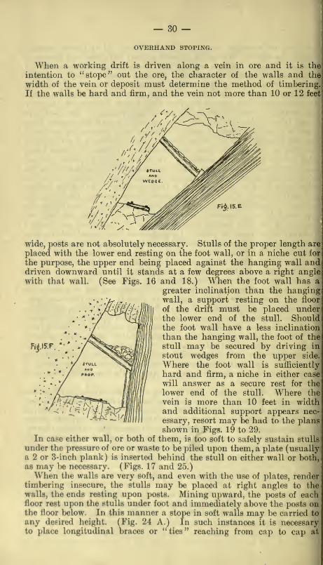
When a working drift is driven along a vein in ore and it is the
intention to "stope" out the ore, the character of the walls and the
width of the vein or deposit must determine the method of timbering.
If the walls be hard and firm, and the vein not more than 10 or 12 feet
wide, posts are not absolutely necessary. Stulls of the proper length are
placed with the lower end resting on the foot wall, or in a niche cut for
the purpose, the upper end being placed against the hanging wall anddriven downward until it stands at a few degrees above a right anglewith that wall. (See Figs. 16 and 18.) When the foot wall has a
greater inclination than the hangingwall, a support resting on the floor
of the drift must be placed underthe lower end of the stull. Shouldthe foot wall have a less inclination
than the hanging wall, the foot of the
stull may be secured by driving in
stout wedges from the upper side.
Where the foot wall is sufhciently
hard and firm, a niche in either case;
will answer as a secure rest for the:
lower end of the stull. Where the
vein is more than 10 feet in widthand additional support appears nec-
essary, resort may be had to the plansshown in Figs. 19 to 29.
In case either wall, or both of them, is too soft to safely sustain stulls
under the pressure of ore or waste to be piled upon them, a plate (usuallya 2 or 3-inch plank) is inserted behind the stull on either wall or both,
as may be necessary. (Figs. 17 and 25.)
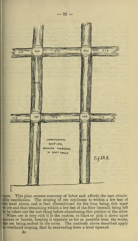
When the walls are very soft, and even with the use of plates, rendertimbering insecure, the stulls may be placed at right angles to thewalls, the ends resting upon posts. Mining upward, the posts of eachfloor rest upon the stulls under foot and immediately above the posts onthe floor below. In this manner a stope in soft walls may be carried to
any desired height. (Fig. 24 A.) In such instances it is necessaryto place longitudinal braces or "ties" reaching from cap to cap at

— 31 —

— 32 —right angles to the stull. These ties may be of smaller dimensions than|the stull and post timbers.
The method shown in Fig. 19 may be employed where the veinexceeds 8 or 10 feet and when sticks sufficiently large to support theweight of ore or waste cannot be obtained. Fig. 20 may be employedin the same manner with a greater width of vein. Both of these instancespresume considerable waste to result from mining, which will, to a greatextent, fill the excavation. Fig. 23 afibrds a firm support to a stull in
a wide place in the vein, and Fig. 22the same in a still broader vertical vein.
Fig. 25 shows how, in a vein of low dipand considerable width, a stull may befirmly supported to retain waste or ore
coming down from the stope above.]
In soft vein and wall rock a substan-
tial method of placing sill, stull, andpost is shown in Fig. 26.
Stulls are placed at distances rang-ing from 2 1 to 6 feet, as may berequired. On them are laid split
lagging, forming a floor. As theminer stands on the floor thus im-provised, he breaks down the ore,
separating it from the waste, if there
be any, and sending the ore into the''level" or main passageway below,
allowing the waste to accumulate onthe floor. The waste often occurs;
to such an extent that a portion of;
it also has to be sent to the surface.
When this is the case, very little
timber is required in the stopes.
When, however, the quantity of wasteis small, it is often necessary to
build a temporary staging upon whichto stand until a sufficient space is cut out above to admit of laying a
second tier of stulls to sustain the floor. Floors are 6 to 8 feet apart
and sometimes even more.
A passageway, called a "mill hole," "chute," or "slide," is left every
30 to 50 feet for the purpose of sending ore to the level below, as the
work progresses upward. The distance between these slides is deter-
mined by the dip of the vein. They may be a greater distance apart in
a steeply inclined vein than in one having a low angle of inclination.
Rock will not run freely on a slope having a slope of less than 40 degrees,
and more is preferable. In cases where the slope angle is low, it is a good
idea to line the slide with plank to facilitate the delivery of the ore to
the level beneath. In opening a stope between levels, the best methodis to make a raise from level to level, building a loading chute at the
bottom. Then at a short distance to one side (15 or 20 feet) a second
raise is carried up about 1 5 feet and connected with the winze. Fromthis point the stope is opened, the excavation being carried upward and the
ore being passed down through the winze to the loading chute. As the
floors are carried up a crib is built around the winze, keeping it constantly
— 33 —
open. This plan secures economy of labor and affords the best obtain-
able ventilation. The stoping of ore continues to within a few feet of
the level above, and is then discontinued for the time being, this massof ore and that remaining within a few feet of the floor beneath being left
to be taken out the last thing before abandoning this portion of the mine.When ore is very rich it is the custom to blast or pick it down upon
canvas or boards, keeping it separate as far as possible from the waste,
the ore being sacked in the mine. The methods above described applyto overhand stoping, that is, excavating from a level upward.
3c
— 34 —UNDERHAND STOPING
Is the term used to indicate an operation the reverse of that just
described, being the method by which the miner takes out the floor of
his level and continues the excavation downward in a series of steps 7 or
8 feet in height. In this method it is best for the economical handlingof the ore, for ventilation, and for drainage, to have established a con-
nection by winze with the level next below, or it will be necessary to hoist
all the ore and water from the stope to the level above. The waste, if
there be any, is thrown on platforms or floors between the face of eachfloor and the winze, slide,* or chute. This method is not advisable
except in narrow, rich veins.
Underhand stoping is not commonly followed, but may be recom-mended in working small veins of very rich ore. It requires usually
more timber than overhand stoping and the timber cannot be recov-
ered as in the latter method.
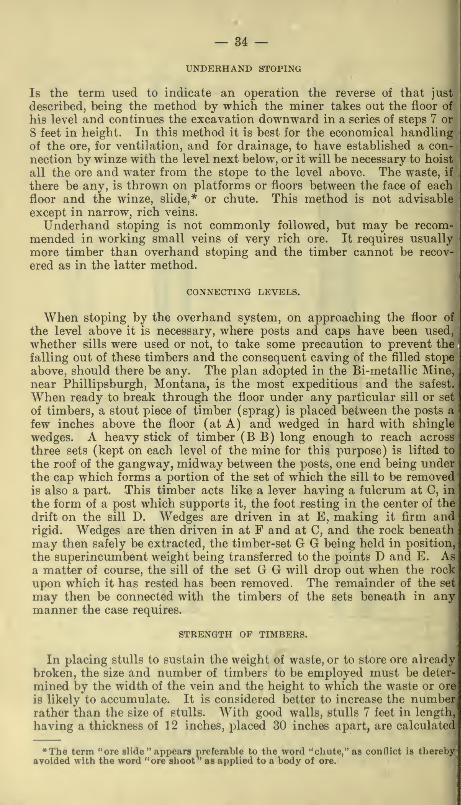
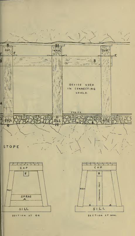
CONNECTING LEVELS.
When stoping by the overhand system, on approaching the floor of
the level above it is necessary, where posts and caps have been used,
whether sills were used or not, to take some precaution to prevent the
falling out of these timbers and the consequent caving of the filled stope
above, should there be any. The plan adopted in the Bi-metallic Mine,
near Phillipsburgh, Montana, is the most expeditious and the safest.
When ready to break through the floor under any particular sill or set
of timbers, a stout piece of timber (sprag) is placed between the posts a
few inches above the floor (at A) and wedged in hard with shingle
wedges. A heavy stick of timber (B B) long enough to reach across
three sets (kept on each level of the mine for this purpose) is lifted to
the roof of the gangway, midway between the posts, one end being underthe cap which forms a portion of the set of which the sill to be removedis also a part. This timber acts like a lever having a fulcrum at C, in
the form of a post which supports it, the foot resting in the center of the
drift on the sill D. Wedges are driven in at E, making it firm andrigid. Wedges are then driven in at F and at C, and the rock beneathmay then safely be extracted, the timber-set G G being held in position,
the superincumbent weight being transferred to the points D and E. Asa matter of course, the sill of the set G G will drop out when the rock
upon which it has rested has been removed. The remainder of the set
may then be connected with the timbers of the sets beneath in anymanner the case requires.
STRENGTH OF TIMBERS.
In placing stulls to sustain the weight of waste, or to store ore already
broken, the size and number of timbers to be employed must be deter-
mined by the width of the vein and the height to which the waste or ore
is likely to accumulate. It is considered better to increase the numberrather than the size of stulls. With good walls, stulls 7 feet in lengtli,
having a thickness of 1 2 inches, placed 30 inches apart, are calculated
The term "ore slide " appears preferable to the word "cliute,"as conflict is therebyayoided with the word "ore shoot^' as applied to a body of ore.
\
RT^ —Rf. ^M
OEVICC USEDI N CONNECTIN Q
LCVCLff.
^<\-^
./,'
STO P E
^ .'.' ' .'.
.
'FFRCAP
5PRAG
SI LL
CAR
SECTION AT «•&
S J L L
SECTION AT H
— 35 —

— 36 —to sustain 60 feet of waste or broken ore in a vein standing at a highangle. After waste has remained in place for some time it settles, andin some instances becomes so firm as to retain its solidity after thestulls have fallen out or have been removed. This need not be expectedin wide veins.
When it becomes necessary to quickly catch up settling stull timbersor caps, a stout post, which will just slip under the sinking timber, is
placed in position and four stout wooden wedges, having the inclinedplanes sloping alternately in different directions, are driven in betweenthe post and stull. This plan will recover the subsidence, if not toogreat, and permit of reinforcing the timbers without losing ground.
THE SAODLC WEDGES,
IN USE AX THCBUCHANAN MINC,
roOLUMNE COUHTY, CAL.
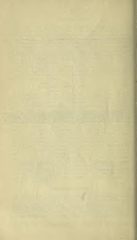
SADDLE BACKS.
A peculiar method of timbering, known as the " saddle, back," is in
vogue in some portions of Colorado. It appears to do well in the lead-
silver mines having good limestone roofs and walls. It may be considered
a modification of the " square-set." It requires less timber and is far less
substantial. It will not do in heavy ground. The details differ withthe various conditions encountered, but the. principles are those obtain-
ing in all other timber systems—the application of resistance to pressure.
The drawings illustrate one method of setting up the saddle back.
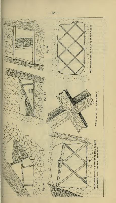
LOADING CHUTES.
The accompanying sketch shows a design for a loading chute or slide,
though they are not always made as elaborate as represented in the
drawing. The inclination of the bottom should exceed 30 degrees, ores
that are soft and wet requiring the slide to have a greater pitch thanthose that are dry. Between the two upright posts which reach fromthe floor of the drift to the roof or to stout stulls overhead, two short
— 37 —
A LOADING CHUTEFig. 31.
uprights are placed, and on top of them, reaching from one to the other,is laid a 4x6 scantling. The gate, furnished with ratchet and wheel andpinion, may be dispensed with, loose boards being substituted, whichmay be pried up, when desired, with a bar. It is well always to buildloading chutes in a substantial manner, so that rebuilding may not be
— 38 —necessary. It is a wise plan to provide false sides and bottoms, whichmay be quickly renewed.The posts supporting loading chutes are not alwaj's placed perpen-
dicular. In steeply inclined veins it is sometimes desirable to set theminclining forward. In vertical veins they are built across the vein.
In square sets, ore bins are constructed within the sets and the chutesare attached to the caps or ties, being arranged at convenient distancesfrom each other.
In some mines, as in the Golden Gate, at Sonora, in Tuolumne County,large storage bins are constructed below the floors of the levels at thehoisting shaft, provided with a loading chute. The skip is stopped at theproper point and loaded. In this manner the necessity of waiting for cars,
or loaded cars and men waiting for the skip, is obviated. In this mineloading chutes are provided on the several levels from the stopes over-
head, as a matter of course being constructed in the ordinary manner.
GREAT CHAMBERS AND SQUARE SETS.
The systems of timbering hereinbefore described refer particularly to
veins having a width not exceeding 12 feet, though mines have beenworked under great difficulties, and where the operations were attendedwith extreme danger, where the distance between walls was 20 and even25 feet. An instance may be mentioned in California in the MountJefierson Mine, at Groveland, in Tuolumne County, where the vein was25 feet from wall to wall. A very ingenious system of timbering wasintroduced in 1854, or thereabouts, consisting of long stulls supportedby wall and inside props 7 feet apart. Longitudinal braces, or ties, werealso introduced to support the timbers longitudinally, but the supportwas insufficient, and a most disastrous case resulted. It is a matter of
absolute impossibility, however, to recover, by the methods thus far given,
all the ore from such great masses of mineral as were found in the Com-stock Lode, where one ore body, the Great Bonanza, measured 340 feet
in width at one point, 600 feet in height, and 1,250 feet in length. Stopesin the various mines of the Homestake group, in the Black Hills, SouthDakota, range from 40 to 150 feet in width and several hundred feet in
length and height. The Caledonia Mine, of this group, measured on the
300-foot level 195 feet horizontally. The Homestake vein at the sur-
face, in the open cut, is 360 feet wide, by actual measurement.In California there are many mines of great value that cannot be
worked by any system of stulls. The Stonewall Mine, in San DiegoCounty, has 20 feet or more of vein in places. The Alvord GoldMine, in San Bernardino County, is a very wide vein. The Odessa,
Occidental, Oriental, Silver Monument, and Waterloo Mines, of the Calico
District, measure 30 to over 100 feet in width. Some of the mines of
Bodie have very broad veins. The Josephine Mine, in Mariposa County,has an immense ore shoot 50 feet wide. The Utica-Stickles Mine, at
Angels, Calaveras County, is 40 to over 100 feet wide, and the Gover Mine,of Amador, has an ore body 30 to 50 feet wide. The Zeila, at Jackson, is
working an immense mass of ore. The Boston Mine, near MokelumneHill, is 40 to 60 feet wide, and some of the ore bodies in the larger quick-
silver mines are of prodigious size. In addition to these there are manyother mines on the gold belt of California where the great width of vein
— 39 —]n'ecliides the extraction of the ore by the use of any system of stulls or
<imple posts and caps.
Veins and ore bodies of large size can be safely, completely, andcheaply mined by using what is known as the " square set " system of
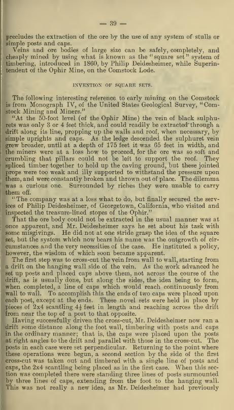
timbering, introduced in 1860, by Philip Deidesheimer, while Superin-tendent of the Ophir Mine, on the Comstock Lode.
INVENTION OF SQUARE SETS.
The following interesting reference to early mining on the Comstockis from Monograph IV, of the United States Geological Survey, "Com-stock Mining and Miners."
''At the 50-foot level (of the Ophir Mine) the vein of black sulphu-rets was only 8 or 4 feet thick, and could readily be extracted' through adrift along its line, propping up the walls and roof, when necessary, bysimple uprights and caps. As the ledge descended the sulphuret vein
grew broader, until at a depth of 175 feet it was 65 feet in width, andthe miners were at a loss how to proceed, for the ore was so soft andcrumbling that pillars could not be left to support the roof. Theyspliced timber together to hold up the caving ground, but these jointed
props were too weak and illy supported to withstand the pressure uponthem, and were constantly broken and thrown out of place. The dilemmawas a curious one. Surrounded by riches they were unable to carry
them off.
"The company was at a loss what to do, but finally secured the serv-
ices of Philip Deidesheimer, of Georgetown, California, who visited andinspected the treasure-lined stopes of the Ophir."That the ore body could not be extracted in the usual manner was at
once apparent, and Mr. Deidesheimer says he set about his task withsome misgivings. He did not at one stride grasp the idea of the squareset, but the system which now bears his name was the outgrowth of cir-
cumstances and the very necessities of the case. He instituted a policy,
however, the wisdom of which soon became apparent.
The first step was to cross-cut the vein from wall to wall, starting froma drift on the hanging wall side of the vein. As the work advanced heset up posts and placed caps above them, not across the course of the
drift, as is usually done, but along the sides, the idea being to form,when completed, a line of caps which would reach continuously fromwall to wall. To accomplish this the ends of two caps were placed uponeach post, except at the ends. These novel sets were held in place bypieces of 2x4 scantling 4^ feet in length and reaching across the drift
from near the top of a post to that opposite.
Having successfully driven the cross-cut, Mr. Deidesheimer now ran adrift some distance along the foot wall, timbering with posts and capsin the ordinary manner; that is, the caps were placed upon the posts
at right angles to the drift and parallel with those in the cross-cut. Theposts in each case were set perpendicular. Returning to the point wherethese operations were begun, a second section by the side of the first
cross-cut was taken out and timbered with a single line of posts andcaps, the 2x4 scantling being placed as in the first case. When this sec-
tion was completed there were standing three lines of posts surmountedby three lines of caps, extending from the foot to the hanging wall.
This was not really a new idea, as Mr. Deidesheimer had previously
— 40 —employed the same method in his drift mine on Forest Hill, when thej
breast was carried in 125 feet wide, the roof being supported by rows of]
posts with continuous caps.
— 41
— 42 —The work thus far performed in the Ophir revealed the fact that an
extremely rich body of ore extended upward from the level where thiswork had been done. The miners were directed to commence stopingupward in the body of soft, black, crumbling ore, and soon a consider-able excavation had been made. It became evident that the groundmust be secured at once.
In the Georgetown Mine, that Mr. Deidesheimer had left but a shorttime before, the vein was vertical, and the walls were so soft and crumb-ling that in order to stope out the mineral he had resorted to the expe-dient of setting one post directly above another, the lower end resting onthe cap, and in this way he managed to work the vein without muchdifficulty.
The Georgetown experience suggested the idea of adopting a similarplan in the Ophir. Accordingly, Mr. Deidesheimer had a mortice cutat the junction of two caps, which were already in place, and having apost framed with a tenon to fit, set the post in place directly above theone resting on the floor below. In a short tim6 four posts were in posi-
tion with the caps upon them as below, together with the frail 2x4scantling, the office of which was to keep the other timbers from falling
down. The first '' square set " timbers, it will be seen, were framed inthe mine, the mortices being cut in the timbers in place. The work of
extracting ore proceeded slowly yet, for the ground had to be secured aswell as possible. It soon became evident, however, that something moresubstantial than 2x4 scantling would be required to keep the timbers in
position, and it was determined to put in timbers of the same dimensionsas those forming caps and posts. This was done at once, and the" square set " was complete in principle, though not in detail. The capsoccupied all the space on top of the posts, leaving no resting place for
the " ties," which had to be supported in some other manner. As theywere looked upon as simply an auxiliary—a support to the posts andcaps—they were only required to be held in position. Accordingly a lot
of iron spikes were made, in shape somewhat like the thumb, having a
sharp point at one end, the other end having a face three fourths of an inchsquare. Two of these spikes were driven into a post at the proper height,
and two in the post opposite, and the tie placed so that the ends rested
upon these iron lugs, wedges being driven in at the ends to secure firm-
ness. The posts and caps were now framed on the surface and delivered
below, ready for use wherever needed. The work of mining now pro-
gressed much more rapidly and the problem seemed solved. Soon after
it was determined to frame the timbers so that the ties might also rest
on the posts. The stopes becoming of such great size, the dimensions of
the timbers were increased and they were then framed as shown in theaccompanying illustrations.
As the work progressed slight changes were made from time to timewhenever any improvement seemed possible. Sills were laid upon thefloors of the levels as a foundation for the timbers above, which hadnow assumed massive proportions. The sill timbers were cut as longas it was possible to get into the mine. The men who were obliged to
handle these ponderous timbers could see no reason why the sills shouldbe longer than the caps, and had from the first looked upon the growthof this new system of timbering with much prejudice. When the great
stopes were carried up from level to level the wisdom of the use of long
sills became apparent, as they permitted the removal of all the ore and

— 43 —the placing of timbers without danger or loss, which could not have beenaccomplished with short sills, as when breaking up through the floor of
a level from below short sills would have nothing to sustain them.When, in the course of ore extraction, the work reached the walls,
additional timbers, called "wall plates," were put in, as shown in the
sketch of timbering in the Ophir Mine. The caps were extended fromthe nearest post to the wall plate, except when a post came within twofeet of the wall plate. In such case the cap extended from the wall
plate to the second post in a single piece.
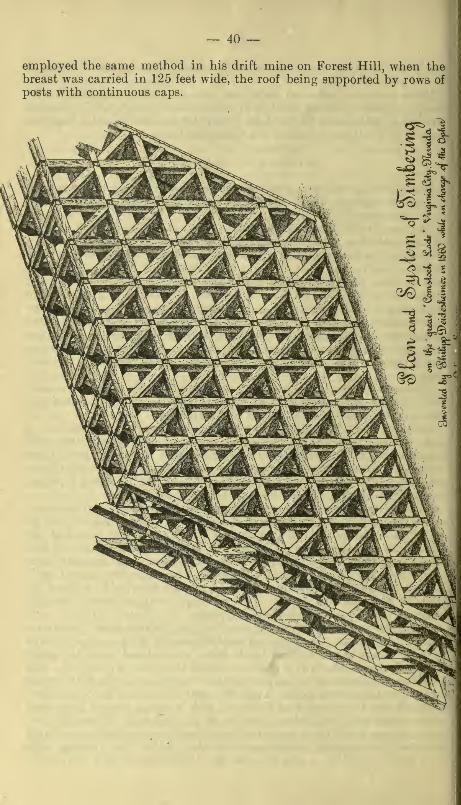
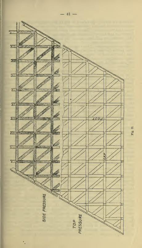
By a close inspection of the drawings the details may be plainly seen.
It will be noticed that a system of braces reaching diagonally across the
sets was also introduced, as well as close lagging on the walls. There is
no doubt that the Ophir was the best timbered mine in the world, butthe Comstock miners who gladly adopted the Deidesheimer system soon
began to disregard many precautions which to them seemed unnecessary.
The diagonal braces were left out, and the ground was found to standabout as well. Then, anxious to still further reduce expense and hurrythe work of extraction, the lagging on the walls were dispensed with, andlater, in somewhat firmer ground, the wall plates were left out, andfinally the timbers were placed in rectangular sets, with only a few propshere and there to the walls and roof, as shown in the drawing of the
Caledonia Gold Mine. The disregard of these important details in
American mines has resulted in numerous disastrous caves.
Owing to the careless timbering in the " Big Bonanza," in the Cali-
fornia and Con. Virginia Mines, cribs of solid timber had to be built,
reaching from the floor to the roof.
The sketch of the Caledonia Mine, in the Black Hills, S. D., repre-
sents the mine as it appeared in the spring of 1883. The main shaft
was sunk in the large vein, the hoisting works being located on the adit
level, 200 feet from the surface, vertical measurement, and 820 feet fromthe mouth of the tunnel. This shaft reached the foot wall on the 300-
foot level, and a large stope was at once opened around the shaft, a pil-
lar of ore 30 feet square being left to support it. The shaft was continuedvertically to the 400-foot level and an extensive stope opened there also.
The gold-bearing rock of the Caledonia is hard white quartz, whichoccurs in bunches and reticulated veins in chloritic schist, and in this
respect resembles some California mines, as the Utica-Stickles, Gover,and some others. In the Caledonia great headers were excavated in
advance of placing the square sets. The timbers were all properly framedand were massive, but there was a disregard of what were consideredthe minor unnecessary details in placing them, particularly on the walls
and against the roof. As these large stopes were extended, too broad anarea was taken out at one time, and the superincumbent weight at lengththrew the timbers out of line, and almost without warning the m*ine
caved, the immense timbers "jack-knifing" and snapping like reeds.
Thousands of tons of ore, the expensive machinery, and a mass of
splintered timbers were dumped in a chaotic mass to the bottom of the400-foot level. There were three causes which led up to this disaster:
The extraction at one time of too large an area of ground; carelessness
in timbering, and the slippery nature of the foot wall (talc schist),
which afforded a poor support to the large pillar of ore.
It is unreasonable to expect a frame of timbers, however strong, to
support the weight of a mountain of rock, and for that reason discretion
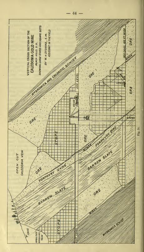
— 44 —
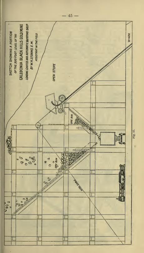
45 —
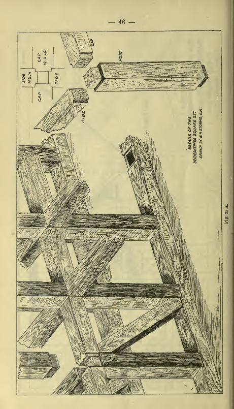
— 46 —
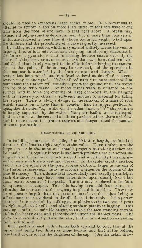
— 47 —should be used in extracting large bodies of ore. It is hazardous to
attempt to remove a section more than three or four sets wide at onetime from the floor of one level to that next above. A breast may-
extend entirely across the deposit or vein, but if more than four sets in
width are removed at one time it allows too much weight to fall uponthe timbers, and the probability of a cave is greatly increased.
By taking out a section, which may extend entirely across the vein or
deposit, three or four sets wide, and carrying the stope up somewhat in
the form of a pyramid, so that on nearing the floor next above only the
space of a single set, or at most, not more than two, be at first removed,and the timbers firmly wedged to the sills before enlarging the excava-tion at that point, all the ore may be extracted, and the operation in
this manner is attended by the least expense and danger. When a
section has been mined out from level to level as described, a secondsection may be attempted. Under all ordinary circumstances it will befound that the timbers will usually support the ground until the stopes
can be filled with waste. At many mines waste is obtained on the
surface, and in some the opening of large chambers in the hangingwall is necessary to obtain a sufiicient amount of material for filling
the stopes. There is always danger in the removal of a mass of rockwhich stands on a base that is broader than its upper portion, or
apex, like the letter "A," while on the other hand a '' V " shaped massis largely supported by the walls. Many ore bodies are lens-shaped;that is, broader at the center than those portions either above or below;and in these masses the greatest expense and danger attend the removalof the upper portion.
CONSTRUCTION OF SQUARE SETS.
In building square sets, the sills, 16 to 20 feet in length, are first laid
down on the floor at right angles to the walls. These timbers are thelargest in use in the mine, and should properly be as long as they canbe handled. At regular intervals shallow depressions are cut across theupper face of the timber one inch in depth and superficially the same size
as the posts which are to rest upon the sill. In the center is cut a mortice,
two thirds the square of the post, at least QxQj and larger as the size of
the timber is increased. Into the mortice, a tenon on the bottom of thepost fits nicely. The sills are laid horizontally and exactly parallel, at
such distances as may have been determined upon, usually 5 or 6 feet
from center to center of the posts. The sets may be placed in the formof squares or rectangles. Two sills having been laid, four posts, con-stituting the four corners of a set, may be placed in position. They maybe of greater length than the posts of sets above, the object being to
afford more room overhead on the sill floor, if desirable. A temporaryplatform is constructed by spiking stout planks to the two sets of postsat right angles to the sills, and placing on them planks or lagging. Thisstaging is built at a suitable height, to enable the men standing thereonto lift the heavy caps and place the ends upon the framed posts. Thecaps are placed directly above the sills; that is, in a direction extendingfrom wall to wall.
Each post is framed with a tenon both top and bottom; that at theupper end being two thirds or three fourths, and that at the bottom,one third or one fourth the thickness of the cap. (See the detail draw-

— 48 —ings.) It is necessary that the bottom of each post shall rest directly
upon the top of that in the set next below. All the timbers mustcarefully framed or it will be found that they will not join properly.Having placed caps upon the posts, the ties may also be lifted into
position, crossing from post to post and resting upon them in the samemanner as the caps, but at right angles to them. Ordinarily caps arebroader on one side than on the other. The broad side is laid upward, thewidth of which is equal to that of the post, which is square. The tie is
equal to the smaller width of the cap. The ties should fit tightly,
and if they do not, must be secured by wedging at the ends. Thebest results are obtained when it is necessary to drive the ties down withmauls.As the work of extracting the ore proceeds the timbering keeps
pace with it. As the stopes are carried upward, set is built upon set,
reaching from one level to another. Temporary working floors are laid,
split lagging being used for this purpose. These floors are moved fromtime to time as the work progresses. Ore broken down on these floors
is shoveled into the bins beneath, or onto the sill floor before the binshave been provided, and from there shoveled or dumped into cars andsent to the surface.
When timbers have been placed the wedges along the walls should bedriven up between the plates and walls, and in all other places whereneeded, to secure firmness and rigidity, and some one man should bedetailed to look after them and see that they remain so; for in large
stopes the ground is constantly shifting more or less, and the weightbeing transferred from one point to another causes the wedges to loosen,
when they must be again tightened to insure safety.
The size of timbers used in the square set system ranges from 8x8 or
8x10 inches to 20x24 or even 24x28 inches, though timbers of the latter
dimensions are often difficult to obtain. When such massive timberscannot be had, the sets may be constructed on a smaller scale, having a
lesser distance between posts, and also less height to the set; thus greater
strength is secured by the employment of a larger number of timbers.
Caps encroach upon the posts 2 to 6 inches according to their dimen-sions, while ties have a rest of 1 to 4 inches, this being also determinedby the size of the timbers. The posts are framed in accordance with thedimensions determined upon, which must be constant, to secure uni-
formity, whether the post be 16x16 or 24x24. As all caps are of the
same length and all ties of an equal length, it is evident that if the
tenons on the posts vary with any difference in the size of the posts
(should any difference occur), the system would soon be out of line. Asthe timbers used are all sawed, it should not be difficult to secure themhaving a uniform size for any single stope. In any event, the tenons at
the top and bottom of the post must have a uniform size regardless of
the dimensions of the post. For instance, should 18-inch posts be in use
on any particular level, framed with 12-inch tenons, if from necessity or
choice a 20-inch or 24-inch post be introduced in the sets, it must have a
12-inch tenon, corresponding with the others. Square timbers are usually
framed with gang saws, and are therefore uniform, and any particular
stick, whether post, cap, or tie, may be used in any portion of the mine.
Posts and caps which come in contact with the wall plate are mostlyframed by hand, to order, careful measurement having first been madeto determine the exact dimensions. Caps which meet the plate within
\'
^
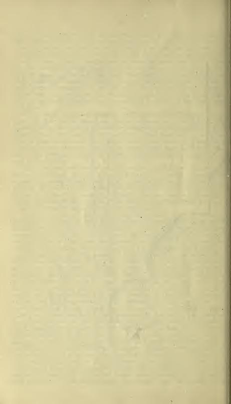

— 49 —
less than two thirds the width of the set are frequently made continuous
from the second post. Wall plates are cut in sections, the length of
which is determined by the conditions in the mine. These are also mostly
framed by hand. The manner of framing and fitting these timbers
will be understood by reference to the drawings.
CAP SILLS AND THEIR USE.
Cap sills are often used in preference to wall plates on the foot wall
of a vein. They are applicable to small stopes as well as great chambers.
As the name implies, these timbers are simply an extension of the cap
from the post nearest the foot wall to the wall where it rests .upon a
hitch cut in the wall (2 feet or more, according to the character of the
ground). It then forms a sill for the post of the set next above, as illus-
trated in the accompanying drawing.
AN IMPROVED SEAT FOR THE POST ON THE SILL.
The method commonly in use for cutting a seat for a post in the sill
:
that of cutting a section an inch deep entirely across the face of the sill,
THC FRAMING FOR TIES
PO ST5 AND SILLS.
in the center of which is a mortise to admit the tenon of the post, hasbeen superseded in some mines by a new practice, which has manyadvantages, particularly the ease with which all rock and other foreign
4c

— 50 —substance may be removed when ready to set the post. The tie or girt
is let in on each side, they being cut out to the depth of one inch at the
ends. The drawing will explain the idea better than a description. Theposts have a tenon one inch only in depth. A longer tenon would afibrd
no additional security or firmness.
RECOVERING LOST GROUND.
A great deal of good ore is sometimes lost by the settling of large veins
upon the timbers of the first few floors of a stope so heavily as to throw th(^
timbers out of line, when bulkheading and filling in must at once l)e
resorted to, to prevent caving. In the Anaconda Mine, of Butte City, Mon-tana, a case of this kind occurred. The timbers on the sill floor were forced
out of line, and it was evident that a disastrous cave was imminent. Thestope was packed full of timber and waste as rapidly as possible and the
level abandoned. A drift was then run from a cross-cut in the foot wall,
60 feet from the vein, and in this lateral drift at distances of 60 feet, anddirectly opposite the chutes in the abandoned stope, as established bythe mine surveyor, a square set was placed. A raise was then carried
up on an incline to the vein, where it was still intact above the filled
stope from each of these points. These raises were timbered with squaresets, which in section would present the appearance of a series of steps.
The rock in which the drift was run was solid granite, but as the foot
wall was approached it was much decomposed and required substantial
timbering. Had the foot wall country rock been firm and hard no timberwould have been necessary, except at the stand on the floor of the drift
where the loading chute was constructed and at the junction of the
winze and foot wall of the vein. Through the winzes thus made the lost
ore was almost entirely recovered.
DIAGONAL BRACES.
These timbers are necessary in heavy ground. It must be borne in
mind that they, in a measure, perform the office of stulls, and shouldnot be placed at right angles to the hanging wall, but at a higher angle.
For instance, supposing the inclination of the hanging wall to be 45degrees, the diagonal braces should stand at 55 degrees. The height andwidth of the sets must be determined by the desired inclination to be
given the diagonal or angle braces, and before this can be determinedthe inclination of the hanging wall must be known. The angle braces
may be of the same size as the posts or a little smaller. These timbers
are not mortised nor framed with tenons, but are slipped in sideways
and secured by thin wedges if they are not tight when put in place.
SIDE PRESSURE.
When the pressure is greater, apparently, from the side than from
overhead, the method of framing and joining these timbers is somewhatdifferent. The cap becomes the post. An examination of the drawings
will convey an idea of the system employed under these conditions.
The tenons at each end of the cap in this case are exactly the same size,
while the tie is also provided with a tenon, but of different style from
that used where the timbers are framed to resist top pressure. The
-D

— 51 —placing of wall plates and angle braces is the same in each system.
The accompanying drawings, showing a horizontal and vertical section
of a corner in both the top and side pressure systems, show plainly the
details of both methods.
BULKHEADS AND CRIBS.
It frequently occurs that bulkheads of solid timber, or cribs filled
with rock, have to be built to sustain sinking roofs which have already
been substantially timbered. Bulkheads are formed by laying massivesquared timbers side by side, filling the space between sets. Upon these
are laid a second layer at right angles to the first, and so on from floor
to roof of the stope. Cribs are constructed by building up timbers in
the form of a hollow square or rectangle, the interior space being filled
with large broken rock, and also extends from floor to roof. Either of
these devices forms a very substantial support to settling ground, thoughsometimes inefficient.
Bulkheads of solid masonry are sometimes built in mine workingsto stop a heavy influx of water. They should be constructed with the
greatest care and in the most substantial manner possible to preventfuture collapse. When it becomes necessary to build a bulkhead of this
kind a section should be cut in the floor, sides, and roof of the drift,
and the masonry extended into these spaces. Water bulkheads are
sometimes built of dry timbers, which, swelling, effectually shut off the
influx of water.
An instance recently came to the knowledge of the writer in which a
large flow of water followed the cutting of a subterranean reservoir bya power drill. As usual in such cases, wooden plugs were inserted anddriven in, but to no purpose, the force of the water driving them out.
The protection of a bulkhead seemed necessary to prevent the flooding
of the mine. An experiment was first tried, which, proving successful,
rendered the bulkhead unnecessary. A section of pipe provided with a
globe valve was inserted in the hole, the valve remaining open until the
pipe was firmly secured by wooden braces and tightly wedged in therock. The valve was then closed and the flow shut off. Provision thenbeing made to handle the water, the valve was opened partly and the
reservoir drained. It seems that this plan might be adopted with ad-vantage where the influx of water interferes with the construction andcompletion of a water-tight bulkhead, for at times the flow of water is
so great that it is almost impossible to construct a bulkhead, owing to
the pressure of the water back of it.
TIMBERING AT THE UTICA MINE.
The largest known.body of ore in California to-day is in the Utica-Stickles Mine, at Angles Camp, Calaveras County. Its extent is, as yet,
unknown. The workings have thus far exposed a mass of gold-bearingrock ranging from 40 to more than 100 feet broad, over 400 feet high, andexceeding 1,000 feet in length. Stopes of this size require a very sub-stantial system of timbering, and the square set system, which has beendescribed at length, is exactly suited to its requirements. It is not in use,
however, but in its stead another system, which is quite similar, andbased on exactly the same principles, still having very important differ-
— 52 —ences. A study of the accompanying timber sketch of the Utica Miiu"
will suffice to make an understanding of the method plain.
The timber used in this mine is exclusively round, peeled pine logs,
which are delivered by contract at the surface works. The cost of these
logs, I am informed, is 10 cents for each inch of diameter, making ;i
16-foot 18-inch log cost $1 80, and a 24-inch log, $2 40. These timbersare all cut into two lengths of 8 feet each. They are mostly over
18 inches in diameter, and occasionally are found as large as 28 and 80
inches in diameter. The posts are framed to 14 inches, top and bottom.the tenon being 4 inches high. Caps are framed to 14 inches at either
end, the tenon being 6 inches long. Thus it will be seen when two adja-
cent caps are placed on a post the tenons will not meet, but will have a
2-inch space between them. This space is filled by driving in a section
of 2-inch plank 14 inches square. At the junction of caps and posts, it
will be noticed, are two ties in place of one, as in the square set system.
These ties range from a foot to 1 6 inches in diameter, and are about 4
feet in length. The lower one has a horn 4 inches in length on its upperhalf. These projections rest upon the shoulders of the posts. The uppertie is tightly wedged between the posts, as shown in the drawing. Thissystem has replaced that formerly in use at the Utica Mine, in whichthe posts were 16 feet high; caps being let into the sides at 8 feet andothers resting on the top. The new system is much preferred and hasmany advantages over the old (a 30-inch post 16 feet in length weighedover 3,300 pounds). In the present system the posts and caps weighfrom 700 to over 1,000 pounds each.
Owing to the impossibility of procuring round timbers that are exactly
uniform in size, the Utica system involves a vast amount of dressing
timbers underground to secure the necessary uniformity in joining.
While the system is one affording great strength when properly placed,
it would seem to possess no advantages over the square set system, andto be more troublesome, cumbersome, and, in the writer's opinion, moreexpensive than the latter, though the first cost of round timber is less
than that of sawed square timber.
No wall plates, excepting short single pieces, are employed, and nosills are laid upon the levels of the floors. It would appear that neglect
to provide sills will in time prove a great disadvantage in connecting
the stopes from level to level.
HANDLING TIMBERS.
The manner of handling timbers at mines depends to a great extent
on the size and number of timbers used, and on the character of the
shaft, whether it be vertical or inclined. In drift mines and mineraldeposits which lie nearly horizontal, they are sent in on flat cars
(trolleys) built for the purpose. When cages are used in vertical shafts
the timbers are set upright on the floor of the cage, lashed together,
and lowered into the mine. At inclines it is a common practice to load
the timbers into the skip and lower them down the shaft in that wayto the desired point.
At the Utica Mine the heavy timbers are handled quickly and easily
on the surface. They are sent from the framing machine to the shafts
on trolleys. Two men are kept busy a great deal of the time in sending
timbers underground. A number of stout chains 8 feet in length are


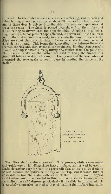
— 53 —jtrovided. In the center of each chain is a 4-inch ring, and at each enda (log, having a point projecting at about 70 degrees 4 inches in length.
One of these dogs is driven into the side of a post or cap somewhatal)0ve the center. The chain is passed over the end of the timber andthe other dog is driven into the opposite side. A spike 6 or 8 inches
long, having a 5-foot piece of rope attached, is driven well into the lower
end of the timber, and it is ready to lower into the mine. Beneath the
skips are stout chains with rings. An extra chain having hooks at
the ends is at hand. This forms the connecting link between the chain
1 leneath the skip and that attached to the timber. Having been securely
hooked the skip is raised slowly, lifting the timber from the platform.
The rope and spike at the bottom are used to bring the timber to a
standstill before the skip is lowered. Having reached the level where it
is wanted the rope again comes into use in landing the timber at the
-lation.
CL-CViCC FOR
LOWERINC TJMSCR
jUNDER TME
' CAGC OR SKIP.
The Utica shaft is almost vertical. This process, while a convenientand quick way of handling these heavy timbers, cannot well be used in
shafts departing very far from the perpendicular, unless a slide of plankbe laid between the guides or runway of the skip, and it would then beadvisable to line the slides with strips of flat iron. It would appearthat timbers might be handled in this manner in shafts having as lowan inclination as 35 degrees, particularly if the slide be lubricated. It
is certainly a superior method to that of loading the timbers into skips.
— 54 —
wh* jh involves much difficulty, particularly in landing them at stations.
Most mines have blocks and tackle at the stations, secured to heavytimbers overhead, for unloading timbers from skips.
It is always a good plan, where possible, to have complete connectionfrom level to level by means, of winzes in veins requiring very largetimbers. The timbers may then be unloaded on the level above wherethey are to be used and lowered through the winze nearest the stope
where they are to be placed, and to the particular floor of the stope
where they are required. Winzes for this purpose should have, if possi-
ble, an inclination of 65 degrees. Where the slope is too low for themto run, however, the timbers may be dragged down, which is certainly
much cheaper and easier than hauling them up.
All timbers should be framed on the surface where possible, as it saves
much time and trouble. Gang saws are much to be preferred to anyother method of framing timbers for square sets. The timbers can, in
this way, be framed as exactly if not more so than by hand, and in onetenth of the time.
In mines where cages are used, when it is necessary to send long tim-
bers down into the mine, as sills for square sets, or long plates, muchtime is saved by boring an auger hole through the timber near the endand passing an iron bar (|-inch) through it. The ends of the bar are
provided with threads and nuts. These ends pass through the ends of
a U-shaped frame, forming a large clevis. The clevis is attached by a
chain to the bottom of the cage, and in this manner lowered to the point
desired. The principle is the same as that employed at the Utica Mine.The drawing on page 53 will convey an idea of the device abovedescribed.

INDEXA
Page.
Alma shaft, Jackson, Cal 21-27
Aiuiconda Mine, Montana .- 50
Angle braces, in square sets 50
Angles, taking in shafts 27
Lionaut inchne, Jackson, Cal. 27
B]'>ark on timbers .-. -. 9
liedrock, swelling _ -- 14
r.eveled notch, the _ - -- 9I'.i-metallic Mine 34" r.locky ground " _ 15
r>olts and dogs for hanging shaft timbers _ 19
I'.owlders from roof - 15
IJraces, diagonal 50
r>reast boards, method of using.. .- - 24^25
r.reasting caps 7-9
liuehanan Mine, Tuolumne County 36JUilkheads and cribs for support 01 roofs 51lUUkheads, water-tight - 51
Cssons, where used 26
averas Consolidated tunnel, timber in 7
edonia Mine, timbering of -. 43-44-45' iiifornia mines, square sets in 38
Caps and posts, in drifts. - 9In square sets 48
Size of... 12
Careless timbering, in Caledonia _ '. 43,44In Con. Virginia _ _ - 43
Chambers and stopes _ _ 27
Chambers, great _ - 38
Chutes or ore slides __- -- 32
Chutes, loading, in drifts _ 32-36-37
In shafts .- — 32Clay linings for shafts... - -- 26
Comstock shafts 21-22-23
Cottonwood for timbers 6
Cribbed shaft ... - 17
Cribs and bulkheads _ 51
DDeidesheimer's square sets 39
Diagonal braces - - --- 50
Dividers in shafts.... - 20-21-24-25
Dogs for hanging timbers - 19
Drainage, importance of -
Drains -
Drift mines, timbering inDrift of Kennedy Mine, timber inDrifts and tunnels
EEl Capitan shaft, Nevada County, Cal —
FFalse setsFissures, precautions with.."Forepohng"Forman shaft, Comstock Lode ---
— 56 —Page.
Framing of shaft timbers 19-22-23Of drift and tunnel timbers 9Of guides in shafts -_ 26-27Of square set timbers ...46-47-48-49
Freezing quicksand and watery ground 26
GGolden Gate Mine, Sonora, loading chute in shaft of 38
Gover Mine, timber tests in GGreat chambers and square sets 38Guides in shafts 26
HHanging bolts and dogs for shafts 19-20
Hanging bolts and dogs, manner of using _. 19-20
Hanging wall, timbering a soft _ 27Handling timbers, on the surface at Utica Mine 52Handling timbers, underground _. 52
Honduras Mine, timbering in , 6
I
Inclines 27Timbering 27Argonaut, at Jackson, Cal. 27
Iron dogs for hanging timbers 19
KKinds of timber used in mines 6
LLagging, how made 10
In drift mines.. 7
Kinds of wood used in making 12
Manner of driving in drifts 10
Manner of driving in shafts 10,24-25• Size of shafts - 10
Levels, connecting 34
Loading chutes, manner of constructing... 32
In drifts... 32
In shafts 36,37Square sets 38
Long wall system 29
Lost ground, recovering _ 50
Lowering timbers 53
MManner of stoping large ore bodies '^
Measuring distance between walls -'7
NNew Almaden Quicksilver Mine, timbering in i'7
OOak for timbers 6
Ophir Mine 43
Ore bins 38Orp Rhont, 34
•r chutes 36,37
toping ''^
Pjtall system 29
re to support roof -- 29
trcaps --- 5)
II joint 12
are set ...: 47 48
t 7 9
•ifting cap 9
)f timbering mines 5


JRia Tl
THIS BOOK IS DUE ON THE LAST DATESTAMPED BELOW
AN INITIAL FINE OF 25 CENTSWILL BE ASSESSED FOR FAILURE TO RETURN THIS BOOKON THE DATE DUE. THE PENALTY WILL INCREASE TO50 CENTS ON THE FOURTH DAY AND TO $1.00 ON THE
SEVENTH DAY OVERDUE.
StP6 ISe5
JAN 3 1S6
FEB 26 19S6
IV EDHEFILEPPSL—
mAPR
SCI '. 'BRAim
Book Slip-20m-5,'59(A2537s4)458

I(1cn\vA or Vx. dK,
PHYSICAL
SCIENCE?
UBRAfry
C3A3
UBKAKYUVIVSRSITY OF CAUFQiJad
pAVia
181585
1175 00998 7051