metric catalog contents - proyectos técnicos y … 56 inch 56 insert overview insert overview the...
TRANSCRIPT


Metric Catalog Contents:
Profile and Copy Milling Program 58
Profile Modular Shrink System 69
Button Insert Cutters 80
APKT Square Shoulder Cutters 84
Aluminum Milling Cutters 86
High Feed Indexable Milling Program 90
Solid Carbide End Mill Program 100
SD Collet & HM Milling Chucks 118
Met
ric C
atal
og C
onte
nts
54

Millstar is an industry leader in producing die and mold profile tooling
and solid carbide tools. Millstar tools are designed for conventional
profile machining, and high speed and hard milling with modern
machine tools and methods.
Millstar Profile Milling Tools represent the latest in profile and contour
milling technology, resulting in shorter machining and lead times, higher
machining accuracy and true contouring results.
Customers include die and mold machining companies, aluminum
extrusion companies, high speed machining mold makers, and
aerospace and medical component industries. Insert tooling is
typically used in roughing and finishing applications.
The Millstar product line is manufactured in the USA, and all tools
are fully traceable. Nearly six decades of cutting tool design and
manufacturing for automotive, aerospace and many other industries,
as well as special design capabilities using 3-D CAD allow us to respond
quickly to requests for special designs.
55
The
Mill
star
Sto
ry

P a g e 5 6
Inch
56
Insert Overview
Inse
rt O
verv
iew
56
The Inserts Millstar inserts are fully ground precision inserts for better chip control, faster metal removal and higher surface accuracies. They are far more accurate than pressed and O.D. sharpened inserts.
• Positive ground chipbreaker or strong negative cutting edge designs guarantee outstanding cutting performance in a wide variety of ferrous and non-ferrous materials.
• A choice of state-of-the-art insert grades, designs and tool coatings allow for optimum speed and feed rates in wet and dry machining. Reduced machining times by 25% to 60% are not uncommon.
• Economical one-piece inserts with two cutting edges are cost-effective for contour milling. True radius geometry is fully CNC-ground for higher machining accuracy and greatly reduced manual finishing and polishing time.
• Choose from side-cutting ball nose inserts with 180 degree nose radius, and popular ball nose inserts with a cutting edge covering 230 degrees for steep wall up-and-down ramping, profiling, contour milling and blending, and for a wider range of applications compared to conventional ball nose tools.
• Select from a variety of flat bottom, back draft and toroid inserts for steep or straight wall milling with long extensions on hard to reach cores, cavities or fillets. Milling with small radii prevents deflection and results in superior finishes and contour accuracies. Available with or without chipbreaker and coating in a variety of corner radii and sizes.
Rock Solid Insert Clamping Cutting insert clamping is highly accurate and rigid. Unique V-pocket design gives a truly positive seat for the insert and will not allow insert movement when milling with a side thrust. “Sandwiched” insert clamping with single locking screw is unsurpassed for rigidity. The advanced design of Millstar inserts eliminates heat-seizing of locking screws or insert movement due to costly locating screws or pins of less advanced design. Positive V-pocket seating eliminates mismatch when changing to fresh inserts. It also eliminates the need to program new length or diameter offsets.

P a g e 5 7
Met
ric
57
Ball Nose Inserts
MBT SuperFinisher Ball Nose InsertPrecision ground, harder grade, for semi-finish and finish milling. Excellent choice for unattended finish milling at small depth and high speeds and feed rates.
MB Ball Nose InsertUnique cutting edge allows performance in all operations in material below 42 HRc; in semi, & finishing operations above. Significant benefits in chip evacuation. Insert geometry allows smoother cutting motion-diminishing heat build up & tool deflection, reduces vibration caused by cutting action.
VRBS Small Ball Nose InsertUsed for semi and finish-milling small radius or detail work, and surface milling in soft and hard steel, cast iron, aerospace and non-ferrous alloys, graphite, etc. Suitable for high speed and hard milling.
RB-N Ball Nose InsertPrecision ground, non- chipbreaker. Best choice for cavity, core and profile milling of pre-hard and fully hard die/mold steels, cast steels and cast iron. Strongest cutting edge design.
RBT InsertPrecision ground for semi-finish and finish milling. Excellent choice for unattended finish milling at small depth and high speed and feed rates.
BS-N Ball Nose InsertSidecutting, non-chipbreaker. Side cutting insert used in cavity and core profiling, for blending of fillets on medium and hard materials.
Flat Bottom Inserts
BDS Flat Bottom InsertPrecision ground, non-chipbreaker. Unique crossover design between flat bottom FB and back draft BD inserts. Allows straight walls with a larger step down than BD, but less cutting forces than FB; allows
higher cutting speeds and feed
FB-R Flat Bottom InsertPrecision ground, with positive ground chipbreaker. Flat bottom insert for shoulder milling, fillet finishing and long reach angular wall finishing of softer materials
HF (High Feed) Inserts Millstar’s new HF insert is designed for High Speed and High Feed machining. The HF is designed to run at high cutting speeds and feed rates with shallow depth of cut. The NEW curved geometry allows the chip to flow up and out of the cut quickly and smoothly allowing for the use of heavy chip loads. The geometry of the new HF insert generates cutting forces upward, toward the spindle, which helps eliminate vibration and deflection, allowing for very high chip loads. The HF insert is designed to fit into Millstar’s standard flat holders, style 4 (CYF, TAF and CBCYF) making these holders more versatile than ever.
Back Draft Inserts
BD-R Back Draft InsertPrecision ground, with positive ground chipbreaker and 7 degree back-taper. Used for milling of cores, cavities, fillets with straight or very steep walls of softer material.
VBD Small Back Draft InsertUsed for semi and finish-milling small radius or detail work, and surface milling in soft and hard steel, cast iron, aerospace and non-ferrous alloys, aluminum alloys, graphite, etc. Suitable for high speed and hard milling.
BD-N Back Draft Insert Precision ground, non-chipbreaker and 7 degree backtaper. Used for milling of cores, cavities, fillets with straight or very steep walls of harder material.
TOBD-NF Back Draft Inserts for Non-Ferrous MaterialsMillstar’s new TOBD-NF insert is specifically designed for high speed and high feed roughing of Aluminum, but also has the versatility to be used for fine finishing as well. This unique cutting edge design allows the chips to flow freely up the flute allowing higher speeds and feeds. The TOBD-NF comes in diameters from 1/2 inch (12mm) up to 1 inch (25mm) and fits into our standard flat type tool holders making the holders more versatile than ever.
CBN TippedFor high speed machining or milling of high hardness materials with longer tool life and superior finishes.
PCD TippedFor carbon milling with longer tool life.
Toroid
TO Toroid Bull Nose InsertPrecision ground, large corner radius & back taper for spiral and pocket milling, milling of pre-hard and hardened flat surfaces at higher speeds than tools with smaller corner radii. Good choice for HS milling of Aluminum
57
Inse
rt O
verv
iew

P a g e 5 8
Inch
58
Profile Milling Program Tool ContentsVRBS, MBT, VBD, BDS Graphite Machining Program 60
SFCY Cylindrical Steel Shank Holder – Ball 62
SFTA Taper Steel Shank Holder – Ball 62
CYF Cylindrical Steel Shank Holder – Flat 63
TAF Taper Steel Shank Holder – Flat 63
TAV, CY, TA Spike-Line Cylindrical Steel Shank 64
CB SFCY Cylindrical Carbide Shank Holder – Ball 64
CB CYF Cylindrical Carbide Shank Holder – Flat 65
CB TAV Spike-Line Taper Carbide Shank Holder – Ball & Flat
65
CB TA Taper Carbide Uni-Shank Holder – Ball & Flat
65
CB CYV Spike Line Taper Carbide Shank – Ball & Flat
66
CB CY Cylindrical Carbide Uni-Shank Holder – Ball & Flat
66
CYFMK Morse Steel Shank Holder – Flat 67
CYMK Morse Steel Shank Holder – Ball 67
SF CY/CYF Screw-on Head – Ball & Flat 68
Solid Carbide Adaptor 68
G1
D
L
Carbide ModularShrink System
69
Inserts 70-75
Cutting Parameters 76-77
58
Sect
ion
Cont
ents

P a g e 5 9
Met
ric
59
Profile Milling Program ToolsMillstar Profile Milling Tools represent the latest in profile and
contour milling technology, providing the competitive edge of
shorter machining and lead times, and the advantages of higher
machining accuracy and true contouring results.
Profi
le M
illin
g Pr
ogra
m T
ools
59
The Millstar AdvantageBetter surface finishes = Reduced finishing work
Faster run & feed speed = Reduced machining time
Increased tool life = Reduced tool changes & cost
Accurate and consistant milling = Reduced manual rework
Balanced milling action, two flute efficiency = Greatly increased metal removal
productivity

Met
ric
60
VRBS
• R
B •
MBT
D
D2
D1
L1L2
VRBS/RB - General Ball Nose Graphite Machining Line, Metric Tool
Ordering Number
Dimensions
Recommended Shank Part Number
Size ØD
Shank ØD1
Neck ØD2
Neck Length L1
Total Length L2
VRBS-6-DMD 6 6 5,7 30 115 CBCYV-06-115-06
VRBS-8-DMD 8 8 7,5 30 115 CBCYV-08-130-08
RB-10-N-DMD 10 10 9,0 32 150 CBCY-10-150-10
RB-12-N-DMD 12 12 10,8 52 165 CBSFCY-12-150-12
RB-16-N-DMD 16 16 14,4 52 170 CBSFCY-16-150-16
RB-20-N-DMD 20 20 18,0 77 225 CBSFCY-20-200-20
RB-25-N-DMD 25 25 22,5 93 230 CBSFCY-25-200-25
RB-30-N-DMD 30 30 27,2 57 230 CBSFCY-30/32-190-32
RB-32-N-DMD 32 32 27,2 57 230 CBSFCY-30/32-190-32
D
D2
D1
L1L2
MBT - Ball Nose Graphite Finishing Line, Metric Tool
Ordering Number
Dimensions
Recommended Shank Part Number
Size ØD
Shank ØD1
Neck ØD2
Neck Length L1
Total Length L2
MBT-10-DMD 10 10 9,0 32 150 CBCY-10-150-10
MBT-12-DMD 12 12 10,8 52 165 CBSFCY-12-150-12
MBT-16-DMD 16 16 14,4 52 170 CBSFCY-16-150-16
MBT-20-DMD 20 20 18,0 77 225 CBSFCY-20-200-20
MBT-25-DMD 25 25 22,5 93 230 CBSFCY-25-200-25
MBT-30-DMD 30 30 27,2 57 230 CBSFCY-30/32-190-32
MBT-32-DMD 32 32 27,2 57 230 CBSFCY-30/32-190-32
* For other holder options, see page 13 (Metric).
Graphite Machining Program

P a g e 6 1
Met
ric
61
VBD/BDS - Flat Bottom Graphite Machining Line, Metric Tool
Ordering Number
Dimensions
Recommended Shank Part Number
Size ØD Radius
Shank ØD1
Neck ØD2
Neck Length L1
Total Length L2
VBD-06-R0,1 6 0,1 6 5,7 30 115 CBCYV-06-115-06
VBD-06-R0,4 6 0,4 6 5,7 30 115 CBCYV-06-115-06
VBD-08-R0,1 8 0,1 8 7,5 30 115 CBCYV-08-130-08
VBD-08-R0,4 8 0,4 8 7,5 30 115 CBCYV-08-130-08
BDS-10-N-0.1 10 0,1 10 9,0 32 150 CBCY-10-150-10
BDS-10-N-0.8 10 0,8 10 9,0 32 150 CBCY-10-150-10
BDS-10-N-1.0 10 1,0 10 9,0 32 150 CBCY-10-150-10
BDS-12-N-0.1 12 0,1 12 10,8 52 165 CBCYF-12-150-12
BDS-12-N-1.0 12 1,0 12 10,8 52 165 CBCYF-12-150-12
BDS-16-N-0.1 16 0,1 16 14,4 52 170 CBCYF-16-150-16
BDS-16-N-1.0 16 1,0 16 14,4 52 170 CBCYF-16-150-16
BDS-16-N-1.3 16 1,3 16 14,4 52 170 CBCYF-16-150-16
BDS-20-N-0.1 20 0,1 20 18,0 77 225 CBCYF-20-200-20
BDS-20-N-1.0 20 1,0 20 18,0 77 225 CBCYF-20-200-20
BDS-20-N-1.6 20 1,6 20 18,0 77 225 CBCYF-20-200-20
BDS-25-N-1.0 25 1,0 25 22,5 93 230 CBCYF-25-200-25
BDS-25-N-2.0 25 2,0 25 22,5 93 230 CBCYF-25-200-25
VBD
• B
DS
* For other holder options, see page 13 (Metric).
Graphite Machining Program

Met
ric
62
D
D2
D1
L1L2
SFCY - Cylindrical Steel Shank Holder, BallTool
Ordering Number
Dimensions
Screw Key
Use with Inserts
Size ØD
Shank ØD1
Neck ØD2
Neck Length L1
Total Length L2 Type Code
SFCY-12-125-12 12 12 10,8 36 125 MS12 T20
MB,MBT,RB-N,BS-N,RBT
SFCY-12-150-12 12 12 10,8 46 150 MS12 T20
SFCY-0500-6.0-12 0.5” 12 11,2 44 152 MS12 T20
SFCY-14-125-16 14 16 12,6 36 125 MS16 T20
SFCY-16-160-16 16 16 14,4 50 160 MS16 T20
SFCY-20-150-20 20 20 18,0 50 150 MS20 T20
SFCY-20-190-20 20 20 18,0 61 190 MS20 T20
SFCY-22-200-25 22 25 19,8 50 200 MS25 T20
SFCY-25-150-25 25 25 22,5 50 150 MS25 T20
SFCY-25-200-25 25 25 22,5 64 200 MS25 T20
SFCY-25-250-25 25 25 22,5 64 250 MS25 T20
SFCY-1000-6.0-25 1.0” 25 22,5 44 152 MS25 T20
SFCY-1000-10.0-25 1.0” 25 22,5 70 254 MS25 T20
SFCY-30/32-190-32 30/32 32 27,2 57 190 MS32 T30
SFCY-30/32-250-32 30/32 32 27,2 76 250 MS32 T30
SFCY-30/32-300-32 30/32 32 27,2 57 300 MS32 T30
D
D2
6°
D1
L1L2
SFTA - Taper Steel Shank Holder, BallTool
Ordering Number
Dimensions
Screw Key
Use with Inserts
Size ØD
Shank ØD1
Neck ØD2
Neck Length L1
Total Length L2 Type Code
SFTA-12-190-16 12 16 10,8 60 190 MS12 T20
MB,MBT,RB-N,BS-N,RBT
SFTA-16-190-20 16 20 14,4 57 190 MS16 T20
SFTA-20-200-25 20 25 18,0 80 200 MS20 T20
SFTA-25-250-32 25 32 22,5 100 250 MS25 T20
SFTA-25-315-32 25 32 22,5 100 315 MS25 T20
SFTA-30/32-250-40 30/32 40 27,2 120 250 MS32 T30
SFTA-30/32-250-42 30/32 42 27,2 120 250 MS32 T30
SFCY
• S
FTA
Profile Milling Program Tools

P a g e 6 3
Met
ric
63
CYF
• TA
F
CYF - Cylindrical Steel Shank Holder, Flat Tool
Ordering Number
Dimensions
Screw Key
Use with Inserts
Size ØD
Shank ØD1
Neck ØD2
Neck Length L1
Total Length L2 Type Code
CYF-10-100-10 10 10 9,0 19 100 MS10 T15
BD-N,BD-R,BDS,FB-R,TO,
TOBD-NF,HF
CYF-12-125-12 12 12 10,8 36 125 MS12 T20
CYF-12-150-12 12 12 10,8 46 150 MS12 T20
CYF-16-160-16 16 16 14,4 50 160 MS16 T20
CYF-20-150-20 20 20 18,0 50 150 MS20 T20
CYF-20-200-20 20 20 18,0 61 200 MS20 T20
CYF-25-150-25 25 25 22,5 50 150 MS25 T20
CYF-25-200-25 25 25 22,5 64 200 MS25 T20
CYF-30/32-190-32 30/32 32 28,6 57 190 MS32 T30
CYF-30/32-250-32 30/32 32 28,6 76 250 MS32 T30
D
D2
6°
D1
L1L2
TAF - Taper Steel Shank Holder, FlatTool
Ordering Number
Dimensions
Screw Key
Use with Inserts
Size ØD
Shank ØD1
Neck ØD2
Neck Length L1
Total Length L2 Type Code
TAF-10-150-12 10 12 9,0 35 150 MS10 T15BD-N,BD-R,BDS,FB-R,TO,
TOBD-NF,HF
TAF-12-190-16 12 16 10,8 60 190 MS12 T20
TAF-16-190-20 16 20 14,4 57 190 MS16 T20
TAF-20-200-25 20 25 18,0 80 200 MS20 T20
TAF-25-250-32 25 32 22,5 100 250 MS25 T20
TAF-25-315-32 25 32 22,5 100 315 MS25 T20
TAF-30/32-250-40 30/32 40 28,6 120 250 MS32 T30
Profile Milling Program Tools

Met
ric
64
TAV,
CY,
TA
• CB
SFC
Y
D
D2
D1
L1 L2
TAV, CY, TA - Spike-Line Cylindrical Steel ShankTool
Ordering Number
Dimensions
Screw Key
Use with Inserts
Size ØD
Shank ØD1
Neck ØD2
Neck Length L1
Total Length L2 Type Code
TAV-06-095-12 6 12 5,7 30 95 MS06N T7VRBS, VBD,MB, MBT,
RB-N, BS-N,BD, BDS,
FB, TO, HF,RBT
TAV-08-095-12 8 12 7,5 32 95 MS08N T7
CY-10-100-10 10 10 9,0 19 100 MS10 T15
CY-10-100-12 10 12 9,0 25 100 MS10 T15
TA-10-125-12 10 12 9,0 35 125 MS10 T15
TA-10-150-12 10 12 9,0 35 150 MS10 T15
D
D2
D1
L1L2
CB SFCY - Cylindrical Carbide Shank Holder, Ball Tool
Ordering Number
Dimensions
Screw Key
Use with Inserts
Size ØD
Shank ØD1
Neck ØD2
Neck Length L1
Total Length L2 Type Code
CBSFCY-12-150-12 12 12 10,8 52 165 MS12 T20MB,MBT,RB-N,BS-N,RBT
CBSFCY-16-150-16 16 16 14,4 52 170 MS16 T20
CBSFCY-20-200-20 20 20 18,0 77 225 MS20 T20
CBSFCY-25-200-25 25 25 22,5 93 230 MS25 T20
CBSFCY-30/32-190-32 30/32 32 27,2 57 230 MS32 T30
P a g e 6 5
Met
ric
65
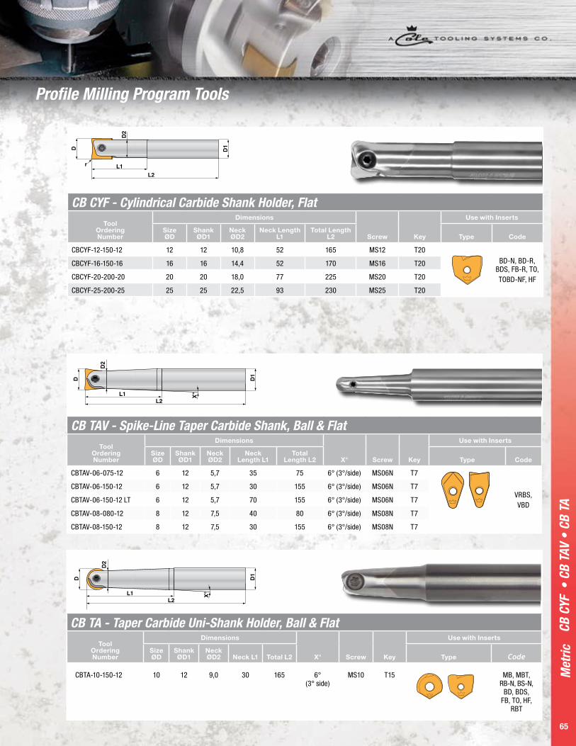
CB CYF - Cylindrical Carbide Shank Holder, FlatTool
Ordering Number
Dimensions
Screw Key
Use with Inserts
Size ØD
Shank ØD1
Neck ØD2
Neck Length L1
Total Length L2 Type Code
CBCYF-12-150-12 12 12 10,8 52 165 MS12 T20
BD-N, BD-R, BDS, FB-R, TO,TOBD-NF, HF
CBCYF-16-150-16 16 16 14,4 52 170 MS16 T20
CBCYF-20-200-20 20 20 18,0 77 225 MS20 T20
CBCYF-25-200-25 25 25 22,5 93 230 MS25 T20
D
D2
X°
D1
L1L2
CB TAV - Spike-Line Taper Carbide Shank, Ball & FlatTool
Ordering Number
Dimensions
X° Screw Key
Use with Inserts
Size ØD
Shank ØD1
Neck ØD2
Neck Length L1
Total Length L2 Type Code
CBTAV-06-075-12 6 12 5,7 35 75 6° (3°/side) MS06N T7
VRBS,VBD
CBTAV-06-150-12 6 12 5,7 30 155 6° (3°/side) MS06N T7
CBTAV-06-150-12 LT 6 12 5,7 70 155 6° (3°/side) MS06N T7
CBTAV-08-080-12 8 12 7,5 40 80 6° (3°/side) MS08N T7
CBTAV-08-150-12 8 12 7,5 30 155 6° (3°/side) MS08N T7
D
D2
X°
D1
L1L2
CB TA - Taper Carbide Uni-Shank Holder, Ball & Flat Tool
Ordering Number
Dimensions
X° Screw Key
Use with Inserts
Size ØD
Shank ØD1
Neck ØD2 Neck L1 Total L2 Type Code
CBTA-10-150-12 10 12 9,0 30 165 6° (3° side)
MS10 T15 MB, MBT, RB-N, BS-N,
BD, BDS, FB, TO, HF,
RBT
CB C
YF •
CB
TAV
• CB
TA
Profile Milling Program Tools

Met
ric
66
Profile Milling Program Tools
CB C
YV •
CB
CY
D
D2
D1
L1L3L2
X˚
CB CYV - Spike Line Taper Carbide Shank, Ball & Flat Tool
Ordering Number
Dimensions
X° Screw Key
Use with Inserts
Size ØD
Shank ØD1
Neck ØD2 Neck L3 Neck L1 Total L2 Type Code
CBCYV-06-115-12 6 12 5,7 30 45 115 1° MS06N T7VRBS,VBDCBCYV-08-100-12 8 12 7,5 30 30 100 1° MS08N T7
D
D2
D1
L1L2
CB CY - Cylindrical Carbide Uni-Shank Holder, Ball & Flat Tool
Ordering Number
Dimensions
Screw Key
Use with Inserts
Size ØD
Shank ØD1
Neck ØD2 Neck L1 Total L2 Type Code
CBCYV-06-115-06 6 6 5,7 30 115 MS06N T7 VRBS,VBD
CBCYV-08-130-08 8 8 7,5 30 130 MS08N T7
CBCY-10-150-10 10 10 9,0 32 150 MS10 T15MB, MBT, RB-N, BS-N, BD, BDS, FB, TO, HF, RBT

P a g e 6 7
Met
ric
67
CYFM
K •
CYM
K
D
D2
L1L2
CYMK - Morse Steel Shank Holder, Ball
Tool Ordering Number
Dimensions
Screw Key
Use with Inserts
Size ØD
Shank ØD1
Neck L1
TotalL2 MORSE Type Code
CYMK-2-130-12 12 10,8 40 130 MK2 MS12 T20MB,MBT,RB-N,BS-N, RBT
CYMK-2-140-16 16 14,4 45 140 MK2 MS16 T20
CYMK-2-150-20 20 18,0 55 150 MK2 MS20 T20
CYMK-3-180-25 25 22,5 70 180 MK3 MS25 T20
CYMK-4-210-32 32 27,2 75 210 MK4 MS32 T30
L2
CYFMK - Morse Steel Shank Holder, Flat
Tool Ordering Number
Dimensions
Screw Key
Use with Inserts
Size ØD
Shank ØD1
Neck L1
Total L2 MORSE Type Code
CYFMK-2-130-12 12 10,8 40 130 MK2 MS12 T20BD-N, BD-R,BDS, FB-R,
TO,TOBD-NF,
HF
CYFMK-2-140-16 16 14,4 45 140 MK2 MS16 T20
CYFMK-2-150-20 20 18,0 55 150 MK2 MS20 T20
CYFMK-3-180-25 25 22,5 70 180 MK3 MS25 T20
CYFMK-4-210-32 32 27,2 75 210 MK4 MS32 T30
Profile Milling Program Tools

Met
ric
68
SF C
Y •
CYF
• So
lid C
arbi
de A
dapt
or
D2
G1
D1
L1 L
Solid Carbide AdaptorTool
Ordering Number Size ØD1 Neck ØD2 Neck L1 Total LThread
G1
CY-10-150-SC-M6 10 9,8 30 150 M6
CY-12-80-12-SC-M6 12 10,8 27 80 M6
CY-12-150-SC-M6 12 10,8 27 150 M6
CY-16-200-SC-M8 16 15,0 31 200 M8
CY-18-130-SC-M10-CH 18 - - 130 M10
CY-18-190-SC-M10-CH 18 - - 190 M10
CY-20-200-SC-M10 20 18,0 36 200 M10
CY-25-170-SC-106-M12 25 24 106 170 M12
CY-25-220-SC-156-M12 25 24 156 220 M12
CY-25-250-SC-M12 25 22,5 44 250 M12
CY-32-170-SC-106-M16 32 29 106 170 M16
CY-32-220-SC-156-M16 32 29 156 220 M16
CY-32-300-SC-M16 32 28,6 52 300 M16
D G1
D1
D2
L1L2
SF CY - Screw-on Head, BallTool
Ordering NumberSize ØD
Diameter D1
Diameter D2
Thread G1
Length L1
Length L2 Screw Key
Use with Inserts
Type Code
SFCY-10-SC-M6 10 9,8 6,5 M6 24 40 MS10 T15
MB, MBT, RB-N, BS-N, RBT
SFCY-12-SC-M6 12 10,8 6,5 M6 26 42 MS12 T20
SFCY-16-SC-M8 16 15,0 8,5 M8 30 48 MS16 T20
SFCY-20-SC-M10 20 18,0 10,5 M10 36 56 MS20 T20
SFCY-25-SC-M12 25 22,5 12,5 M12 44 65 MS25 T20
SFCY-32-SC-M16 32 28,6 16,5 M16 50 74 MS32 T30
G1
D1
D2
L1L2
CYF - Screw-on Head, FlatTool
Ordering Number Size ØDDiameter
D1Diameter
D2Thread
G1Length
L1Length
L2 Screw Key
Use with Inserts
Type Code
CYF-10-SC-M6 10 9,8 6,5 M6 24 40 MS10 T15
BD-N, BD-R,BDS, FB-R,
TO,TOBD-NF, HF
CYF-12-SC-M6 12 10,8 6,5 M6 26 42 MS12 T20
CYF-16-SC-M8 16 15,0 8,5 M8 30 48 MS16 T20
CYF-20-SC-M10 20 18,0 10,5 M10 36 56 MS20 T20
CYF-25-SC-M12 25 22,5 12,5 M12 44 65 MS25 T20
CYF-32-SC-M16 32 28,6 16,5 M16 50 74 MS32 T30

69
Carbide Modular Shrink System Millstar’s Carbide Modular Shrink System offers versatility,
strength and accuracy. The carbide shank offers strength and
rigidity and the shrink tolerances offer better accuracy than screw
on type systems. These tools are designed for high speed machining
and hard metal machining and will allow for better tool life as
well as better surface finishes.
Carb
ide
Mod
ular
Shr
ink
Syst
em

Met
ric
70
Carb
ide
Mod
ular
Shr
ink
Syst
em
Carbide Modular Shrink SystemInserts & Holders 71
Profile Milling Program Tools
72-73
BDS Series in PCD and CBN Tipped
74
Copy Milling Program Tools
75
Cutting Parameters 76-77
Shrink System IdentificationHead, SteelMeasurement System
Denotes Type
Diameter Size
Connection Compatability
Imperial CHY 500 T1Metric CHY 12 T1Shank, CarbideMeasurement System
Denotes Type
Diameter Size
Overall Length
Connection Compatability
Imperial CSS 500 2.29 T1Metric CSS 12 75 T1
“CHTA” or “CHTAV” = Taper Neck Head“CHY” = Straight Head for Ball Insert
“CHF” = Straight Head for Flat Type Insert
Imperial = Hundredths of an Inch
Metric = Millimeters
70

P a g e 7 1
Met
ric
71
Insert Shrink Fit HEAD Shrink Fit SHANK
Type Code Tool Number
Dimensions
Tool Number
Dimensions
ØD1 L1 L2 ØD1 L1 L2
VBD, VRBS CHTAV-06-T1 11,7 43,2 22,3
CSS-12-75-T1 CSS-12-125-T1
12 12
73,60 124,40
15,24 15,24
CHTAV-08-T1 11,7 43,2 20,9
TO, HF, FB, BDS, MB,MBT, BD, TOBD-NF, RBT CHTA-10-T1 11,7 43,2 21,5
RB, MB, MBT, BS, RBTCHY-12-T1 11,7 43,2 21,5
FB, BD, BDS, HF, TO, TOBD-NFCHF-12-T1 11,7 43,2 21,5
BS, RB, MB, MBT, RBTCHY-16-T2 14,0 38,2
CSS-16-105-T2 CSS-16-180-T2
16 16
104,80 180,80
16,51 16,51FB, BD, BDS, HF, TO, TOBD-NF
CHF-16-T2 14,0 38,2
RB, BS, MB, MBT, RBTCHY-20-T3 17,1 48,3
CSS-20-95-T3 CSS-20-175-T3 CSS-18-150-T3
20 20 18
96,50 172,70
150
17,78 17,78 17,78FB, BD, BDS, HF, TO, TOBD-NF
CHF-20-T3 17,1 48,3
Carbide Modular Shrink System, Metric
Carb
ide
Mod
ular
Shr
ink
Syst
em In
sert
s &
Hol
ders
6˚L2
L1
T1
L2
L1
D1
11,05
CHTAV-06-T17,97
CHY-12-T1CHF-12-T1
6˚
T1D1
L2
L1
7.67CHTA-10-T1
T1D1
6˚
L2
L1
T1D1
10,43CHTAV-08-T1
L2
L1
D1
T1
T2
L1
13,97
CHY-16-T2 CHF-16-T2
L2
L1
D1
T2
T3
L1
17,14
CHY-20-T3CHF-20-T3
L2
L1
D1
T3

Met
ric
72
VRBS
, VBD
, HF
Inse
rts
• HF
Cut
ting
Reco
mm
enda
tions
Small Ball Nose & Back Draft Inserts
VRBSTool Ordering
Number
Dimensions Grade
DescriptionD L R XRN TLN HSN
2˚
L
VRBS-6 6 8,10 3 • • • Used for semi and finish-milling small radius or detail work, and surface milling in soft and hard steel, cast iron, aerospace and non-ferrous alloys, graphite, etc. Suitable for high speed and hard milling.
VRBS-8 8 4,50 4 • • •
Metric High Feed Inserts
HFTool Ordering
Number
Dimensions Grade
DescriptionD L PR XRN TLN HSN
D
L
HF-10 10 3 1,00 • • • Millstar HF insert is designed for High feed and High speed machining. It runs at high cutting speed and feed rates with shallow depth of cut. It allows the chip to flow up and out of the cut quickly. It allows heavy chip loads.
HF-12 12 4 1,43 • • •
HF-16 16 5 1,94 • • •
HF-20 20 6 2,26 • • •
HF-25 25 7 2,82 • • •
VBDTool Ordering
Number
Dimensions Grade
D L R XRN TLN HSN
DLR
1̊
VBD-06 6 8,6 0,1/0,4 • • • Used for semi and finish-milling small radius or detail work, and surface milling in soft and hard steel, cast iron, aerospace and non-ferrous alloys, graphite, etc. Suitable for high speed and hard milling
VBD-08 8 5 0,1/0,4 • • •
Cutting Recommendations for High Feed Inserts Work
MaterialMaterial
HardnessCutting Depth at Diameter
ap maxCutting Width
InsertCoating
Type Recom.
Cut speed at D
Max feed per tooth fz at cutting insert diameter D
USA/W.- Nr./JIS Hrc 10 12 16 20 25 Ae max sfm/min 10 12 16 20 25
H13/1,2344/
SKD61<41 0,38 0,46 0,61 0,76 0,95 60 - 75% HF XRN/HSN 157 - 218 0,28~0,48 0,36~0,56 0,051~0,71 0,66~0,86 0,85~1,05
H13/1,2344/
SKD6141-50 0,32 0,38 0,51 0,64 0,80 60 - 75% HF XRN/HSN 126 - 187 0,22~0,42 0,28~0,48 0,41~0,61 0,54~0,74 0,70~0,90
H13/1,2344/
SKD6151+ 0,26 0,31 0,42 0,52 0,65 60 - 75% HF HSN 96 - 157 0,16~0,36 0,21~0,41 0,32~0,52 0,42~0,62 0,55~0,75
A2/1,2363/
SKD12<41 0,38 0,46 0,61 0,76 0,95 60 - 75% HF XRN/HSN 157 - 218 0,28~0,48 0,36~0,56 0,51~0,71 0,66~0,86 0,85~1,05
A2/1,2363/
SKD1214-50 0,32 0,38 0,51 0,64 0,80 60 - 75% HF XRN/HSN 126 - 187 0,220~0,42 0,28~0,48 0,32~0,52 0,54~0,74 0,70~0,90
A2/1,2363/
SKD1251+ 0,26 0,31 0,42 0,52 0,65 60 - 75% HF HSN 96 - 157 0,16~0,36 0,21~0,41 0,51~0,71 0,42~0,62 0,55~0,75
P20/1,2330 <41 0,38 0,46 0,61 0,76 0,95 60 - 75% HF XRN/HSN 157 - 218 0,28~0,48 0,36~0,56 0,41~0,61 0,66~0,86 0,85~1,05
P20/1,2330 14-50 0,32 0,38 0,51 0,64 0,80 60 - 75% HF XRN/HSN 126 - 187 0,22~0,42 0,28~0,48 0,51~0,71 0,54~0,74 0,70~0,90
D2/1,2379/
SKD11<41 0,38 0,46 0,61 0,76 0,95 60 - 75% HF XRN/HSN 157 - 218 0,28~0,48 0,36~0,56 0,41~0,71 0,66~0,86 0,85~1,05
D2/1,2379/
SKD1114-50 0,32 0,38 0,51 0,64 0,80 60 - 75% HF XRN/HSN 126 - 187 0,22~0,42 0,28~0,48 0,41~0,61 0,54~0,744 0,70~0,90
D2/1,2379/
SKD1151+ 0,26 0,31 0,42 0,52 0,65 60 - 75% HF HSN 96 - 157 0,16~0,36 0,21~0,41 0,32~052 0,42~0,62 0,55~0,75
Grey Cast Iron/
GG<41 0,38 0,46 0,61 0,76 0,95 60 - 75% HF XRN/HSN 157 - 218 0,282~0,48 0,36~0,56 0,51~0,71 0,66~0,86 0,85~1,05
Cast Iron/GGG 41+ 0,38 0,46 0,61 0,76 0,95 60 - 75% HF XRN/HSN 157 - 218 0,28~0,48 0,36~0,56 0,51~0,71 0,66~0,86 0,85~1,05
Profile Milling Program Tools
P a g e 7 3
Met
ric
73
Flat
Bot
tom
, Bac
k Dr
aft &
Tor
oid
Met
ric In
sert
s
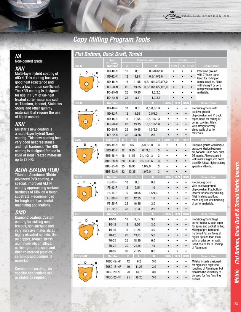
Flat Bottom, Back Draft, Toroid
BD-N
Tool Ordering Number
Dimensions Grade
DescriptionD L R XRN TLN HSN
D
L
R BD-10-N 10 8,5 0,5/0,8/1,0 • • • Precision ground with 7º back taper. Used for milling of cores, cavities, fillets with straight or very steep walls of harder materials.
BD-12-N 12 9,95 0,5/1,0/2,0 • • •
BD-16-N 16 11,55 0,5/1,0/1,3/2,0/3,0 • • •
BD-20-N 20 13,35 0,5/1,0/1,6/2,0/3,0 • • •
BD-25-N 25 19,95 1,0/2,0 • • •
BD-32-N 32 8,5 1,0/2,6 • • •
BD-R Number D L R XRN TLN HSN Description
D
L
RBD-10-R 10 8,5 0,5/0,8/1,0 • • • Precision ground with
positive ground chip-breaker and 7º back taper. Used for milling of cores, cavities, fillets with straight or very steep walls of softer materials.
BD-12-R 12 9,95 0,5/1,0 • • •
BD-16-R 16 11,55 0,5/1,0/1,3 • • •
BD-20-R 20 13,35 0,5/1,0/1,6 • • •
BD-25-R 25 19,95 1,0/2,0 • • •
BD-32-R 32 23,35 2,6 • • •
TO Number D L R XRN TLN HSN Description
D
L
R TO-10 10 8,65 3,0 • • • Precision ground large corner radius & back taper for spiral and pocket milling. Milling of pre-hard and hardened flat surfaces at higher speeds than tools with smaller corner radii. Good choice for HS milling of Aluminum.
TO-12 12 9,20 3,0 • • •
TO-16 16 11,25 4,0 • • •
TO-20 20 13,15 5,0 • • •
TO-25 25 18,25 6,0 • • •
TO-30 30 22,15 7,5 • • •
TO-32 32 21,95 8,0 • • •
TOBD-NF Number D L R XRN TLN HSN Description
D
L
R TOBD-12-NF 12 9,2 3,0 • • • Millstar inserts designed for high seed high feed roughing of Aluminum, but also has the versatility to be used for fine finishing as well.
TOBD-16-NF 16 11,25 3,0 • • •
TOBD-20-NF 20 13,15 3,0 • • •
TOBD-25-NF 25 18,25 3,0 • • •
BDS Number D L R L1 XRN TLN HSN Description
BDS-10-N 10 8,5 0,1/0,8/1,0 3 • • • Precision ground with unique crossover design between flat bottom FB and back draft DB inserts. Allows straight walls with a larger step down than BD. Allows higher cutting speeds and feeds.
BDS-12-N 12 9,95 0,1/1,0 3 • • •
BDS-16-N 16 11,55 0,1/1,0/1,3 3 • • •
BDS-20-N 20 13,35 0,1/1,0/1,6 3 • • •
BDS-25-N 25 19,95 1,0/2,0 3 • • •
BDS-32-N 32 23,35 1,0/2,0 3 • • •
FB-R Number D L R XRN TLN HSN Description
D
L
R FB-10-R 10 8,5 0,8 • • • Precision ground with positive ground chip-breaker. Flat bottom inserts for shoulder milling, fillet finishing and long reach angular wall finishing of softer materials.
FB-12-R 12 9,15 1,0 • • •
FB-16-R 16 10,65 0,5/1,3 • • •
FB-20-R 20 12,25 1,6 • • •
FB-25-R 25 16,35 2,0 • • •
FB-32-R 32 21,3 2,6 • • •
Copy Milling Program Tools
NA Non-coated grade.
XRN Multi-layer hybrid coating of AlCrN. This coating has very good heat resistance and also a low friction coefficient. The XRN coating is designed for use in HSM of un-heat treated softer materials such as Titanium, Inconel, Stainless Steels and other gummy materials that require the use of liquid coolant.
HSN Millstar’s new coating is a multi-layer hybrid Nano coating. This new coating has very good heat resistance and high hardness. The HSN coating is designed for use in HSM of Heat Treated materials up to 72 HRc.
ALTiN-EXALON (TLN) Titanium Aluminum Nitride advanced PVD coating. A special, improved ALTiN coating approaching surface hardness of CBN on a tough substrate. Recommended for tough and hard metal machining applications.
DMD Diamond coating. Custom coating for cutting non-ferrous, non-metallic and very abrasive materials at highly elevated speeds. Use on copper, bronze, brass, aluminum-silicon alloys, carbon graphite, solid and fiber-reinforced plastics, ceramics and composite materials.
Custom tool coatings for specific applications are available by request.

Back
Dra
ft
Radius Ordering Numbers:For .015 use ordering # .015 • For 1/32” use ordering # 02 1/16” use ordering # 04 For 1/8” use ordering # 08Example: 1/2” BDS-0500N-04-PCD or CBN74
NEW!Higher cutting speeds and feeds with new
Back Draft Tools
Back Draft
BDS
Tool Ordering Number
Dimensions Grade
DescriptionD L R L1 XRN TLN HSN
BDS-10-N 10 8,5 0,1/0,8/1,0 3 • • • Precision ground with unique crossover design between flat bottom FB and back draft BD inserts. Allows straight walls with a larger step down than BD. Allows higher cutting speeds and feeds.
BDS-12-N 12 9,95 0,1/1 3 • • •
BDS-16-N 16 11,55 0,1/1/1,3 3 • • •
BDS-20-N 20 13,35 0,1/1/1,6 3 • • •
BDS-25-N 25 19,95 1/2 3 • • •
BDS Series in PCD and CBN Tipped
PCD Tipped For carbon milling with longer tool life
CBN TippedFor high speed machining or milling of high hardness materials with longer tool life and superior finishes.

P a g e 7 5
Met
ric
75
Ball
Nose
Inse
rts
Ball Nose Inserts
BS-NTool Ordering
Number
Dimensions Grade
DescriptionD L S XRN TLN HSN
D
SL
BS-10-N 10 9,50 3,65 • • • Sidecutting, non-chipbreaker. Side cutting insert used in cavity and core profiling, for blending of fillets on medium and hard materials.
BS-12-N 12 8,80 2,90 • • •
BS-16-N 16 10,70 2,85 • • •
BS-20-N 20 12,75 2,85 • • •
BS-25-N 25 17,20 4,85 • • •
BS-30-N 30 20,00 5,10 • • •
BS-32-N 32 21,00 5,30 • • •
MB Number D L XRN TLN HSN Description
D
L
MB-10 10 8,65 • • • Unique cutting edge allows performance in all operations in material below 42 HRc; in semi, & finishing operations above. Significant benefits in chip evacuation. Insert geometry allows smoother cutting motion-diminishing heat build up & tool deflection, reduces vibration caused by cutting action.
MB-12 12 9,20 • • •
MB-16 16 11,25 • • •
MB-20 20 13,15 • • •
MB-25 25 18,25 • • •
MB-30 30 22,15 • • •
MB-32 32 21,95 • • •
MBT Number D L XRN TLN HSN Description
D
L
MBT-10 10 8,65 • • • Precision ground, harder grade, for semi-finish and finish
milling. Excellent choice for unattended finish milling at
small depth and high speeds and feed rates.
MBT-12 12 9,20 • • •
MBT-16 16 11,25 • • •
MBT-20 20 13,15 • • •
MBT-25 25 18,25 • • •
MBT-30 30 22,15 • • •
MBT-32 32 21,95 • • •
RB-N Number D L XRN TLN HSN Description
D
L
RB-10-N 10 9,50 • • • Precision ground, non-chipbreaker. Best choice for cavity, core and profile milling of pre-hard and fully hard die/mold steels, cast steels and cast iron. Strongest cutting edge design.
RB-12-N 12 9,20 • • •
RB-14-N 14 9,45 • • •
RB-16-N 16 11,25 • • •
RB-20-N 20 13,15 • • •
RB-22-N 22 17,45 • • •
RB-25-N 25 18,25 • • •
RB-30-N 30 22,15 • • •
RB-32-N 32 21,95 • • •
RBTRBT Number D L XRN TLN HSN Description
RB-10-T 10 8,65 • • • Precision ground for semi-finish and finish milling. Excellent choice for unattended finish milling at small depth and high speed and feed rates.
RB-12-T 12 9,20 • • •
RB-16-T 16 11,25 • • •
RB-20-T 20 13,15 • • •
RB-25-T 25 18,25 • • •
RB-30-T 30 22,15 • • •
RB-32-T 32 21,95 • • •
D
L
Copy Milling Program Tools
NA Non-coated grade.
XRN Multi-layer hybrid coating of AlCrN. This coating has very good heat resistance and also a low friction coefficient. The XRN coating is designed for use in HSM of un-heat treated softer materials such as Titanium, Inconel, Stainless Steels and other gummy materials that require the use of liquid coolant.
HSN Millstar’s new coating is a multi-layer hybrid Nano coating. This new coating has very good heat resistance and high hardness. The HSN coating is designed for use in HSM of Heat Treated materials up to 72 HRc.
ALTiN-EXALON (TLN) Titanium Aluminum Nitride advanced PVD coating. A special, improved ALTiN coating approaching surface hardness of CBN on a tough substrate. Recommended for tough and hard metal machining applications.
DMD Diamond coating. Custom coating for cutting non-ferrous, non-metallic and very abrasive materials at highly elevated speeds. Use on copper, bronze, brass, aluminum-silicon alloys, carbon graphite, solid and fiber-reinforced plastics, ceramics and composite materials.
Custom tool coatings for specific applications are available by request.

Met
ric
76
Choosing Cutting Parameters/Calculating Cutting Speed and Feed – METRIC For Ball Nose Inserts
Cutt
ing
Para
met
ers
/ Cut
ting
Spee
d &
Fee
d
Table 1 - Cutting Conditions for Using Steel Shank Holders
Working Material Hardness Grade Vc m/min
Feed fn (mm/Rev)
Ap Max Ae MaxInsert Diameter (mm)
6 8 10 12 16 20 25 30 32
Low Alloy Steel(1.7225) 200-280HB TLN, HSN 150-200 0,2 0,3 0,4 0,4 0,5 0,5 0,6 0,6 0,6 .15 x D .15 x D
Alloy & Die Steel (1.2311, P20, DME2/3/5) 32-42HRC TLN, HSN 100-150 0,15 0,25 0,3 0,4 0,4 0,4 0,5 0,5 0,5 .20 x D .20 x D
Tool Steel (1.2344, 1.2379) 42-52HRC TLN, HSN 120-160 0,15 0,25 0,3 0,4 0,5 0,5 0,6 0,6 0,6 .20 x D .20 x D
Stainless Steel (1.4301, 1.4401) 200-350HB XRN, TLN, HSN 90-120 0,15 0,25 0,3 0,4 0,4 0,4 0,5 0,5 0,5 .20 x D .20 x D
Gray Cast Iron (GG25-GG30) 160-260HB TLN, HSN 200-360 0,2 0,3 0,4 0,5 0,6 0,6 0,7 0,7 0,7 .10 x D .10 x D
Nodular Cast Iron (GGG60-GGG70) 180-300HB TLN, HSN, HSN 150-300 0,2 0,3 0,4 0,5 0,6 0,6 0,7 0,7 0,7 .15 x D .15 x D
Copper Alloy 80-150HB XRN 150-200 0,25 0,4 0,5 0,6 0,7 0,7 0,8 0,8 0,8 .10 x D .10 x D
Aluminum Alloys 30-120HB XRN 200-300 0,25 0,4 0,5 0,6 0,7 0,7 0,8 0,8 0,8 .6 x D .6 x D
Graphite TLN 200-400 0,3 0,5 0,6 0,7 0,8 0,8 0,9 0,9 0,9 .5 x D .5 x D
Ni & Co Based Alloy 250-320HB XRN, HSN 30-70 0,15 0,2 0,3 0,4 0,4 0,5 0,5 0,6 0,6 .30 x D .30 x D
Titanium Alloy (Annealed) <350HB XRN, HSN 50-120 0,15 0,2 0,25 0,35 0,35 0,4 0,45 0,5 0,5 .33 x D .33 x D
Titanium Alloy (Sol. Treated/Aged) <380HB XRN, HSN 40-90 0,1 0,15 0,2 0,3 0,3 0,35 0,4 0,45 0,45 .35 x D .35 x D
Harden Steel (1.2344, 1.2379) 45-55HRC TLN, HSN 70-90 0,15 0,25 0,3 0,4 0,5 0,5 0,6 0,6 0,6 .30 x D .30 x D
Table 2 - Cutting Conditions for Using Carbide Shank Holders
Working Material Hardness Grade Vc m/min
Feed fn (mm/Rev)Ap Max Ae Max Insert Diameter (mm)
6 8 10 12 16 20 25 30 32
Low Alloy Steel (1.7225) 200-280HB TLN, HSN 260-380 0,3 0,4 0,4 0,5 0,6 0,6 0,7 0,7 0,7 .15 x D .50 x D
Alloy & Die Steel (1.2311, P20, DME2/3/5) 32-42HRC TLN, HSN 250-330 0,25 0,3 0,3 0,4 0,5 0,5 0,6 0,6 0,6 .20 x D .50 x D
Tool Steel (1.2344, 1.2379) 42-52HRC TLN, HSN 240-320 0,25 0,3 0,3 0,4 0,5 0,5 0,6 0,6 0,6 .20 x D .50 x D
Stainless Steel (1.4301, 1.4401) 200-350HB XRN, TLN, HSN 200-260 0,25 0,3 0,4 0,5 0,6 0,65 0,7 0,8 0,8 .20 x D .50 x D
Gray Cast Iron (GG25-GG30)
160-260HB TLN, HSN 360-450 0,35 0,45 0,5 0,5 0,6 0,7 0,8 1,0 1,0 .10 x D .40 x D
Nodular Cast Iron (GGG60-GGG70) 180-300HB TLN, HSN 300-400 0,3 0,4 0,4 0,5 0,6 0,6 0,7 0,8 0,8 .15 x D .15 x D
Copper Alloy 80-150HB XRN 300-400 0,3 0,4 0,4 0,5 0,6 0,6 0,7 0,7 0,7 .10 x D .40 x D
Aluminum Alloys 30-120HB XRN 400-500 0,3 0,4 0,5 0,6 0,7 0,7 0,8 0,8 0,8 .6 x D .40 x D
Graphite TLN, HSN 600-800 0,3 0,5 0,6 0,7 0,8 0,8 0,9 0,9 0,9 .5 x D .40 x D
Ni & Co Based Alloy 250-320HB XRN, HSN 80-110 0,25 0,3 0,4 0,4 0,5 0,6 0,6 0,7 0,7 .30 x D .50 x D
Titanium Alloy (Annealed) <350HB XRN, HSN 150-230 0,15 0,2 0,25 0,35 0,35 0,4 0,45 0,5 0,5 .33 x D .50 x D
Titanium Alloy (Sol. Treated/Aged) <380HB XRN, HSN 110-220 0,1 0,15 0,2 0,3 0,3 0,35 0,4 0,45 0,45 .35 x D .50 x D
Harden Steel (1.2344, 1.2379) 45-55HRC TLN, HSN 120-220 0,2 0,25 0,3 0,4 0,5 0,5 0,6 0,6 0,6 .30 x D .30 x D
P a g e 7 7
Met
ric
77
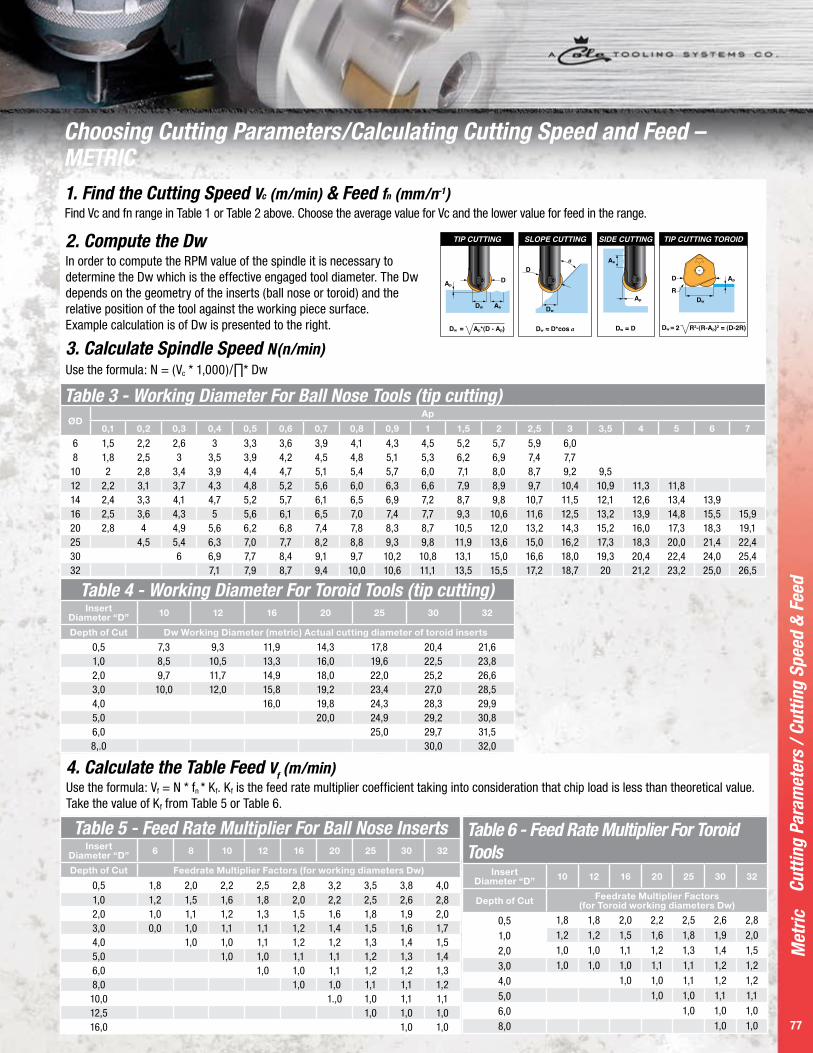
4. Calculate the Table Feed Vf (m/min)Use the formula: Vf = N * fn * Kf. Kf is the feed rate multiplier coefficient taking into consideration that chip load is less than theoretical value. Take the value of Kf from Table 5 or Table 6.
Table 3 - Working Diameter For Ball Nose Tools (tip cutting)ØD
Ap
0,1 0,2 0,3 0,4 0,5 0,6 0,7 0,8 0,9 1 1,5 2 2,5 3 3,5 4 5 6 7
6 1,5 2,2 2,6 3 3,3 3,6 3,9 4,1 4,3 4,5 5,2 5,7 5,9 6,08 1,8 2,5 3 3,5 3,9 4,2 4,5 4,8 5,1 5,3 6,2 6,9 7,4 7,710 2 2,8 3,4 3,9 4,4 4,7 5,1 5,4 5,7 6,0 7,1 8,0 8,7 9,2 9,512 2,2 3,1 3,7 4,3 4,8 5,2 5,6 6,0 6,3 6,6 7,9 8,9 9,7 10,4 10,9 11,3 11,814 2,4 3,3 4,1 4,7 5,2 5,7 6,1 6,5 6,9 7,2 8,7 9,8 10,7 11,5 12,1 12,6 13,4 13,916 2,5 3,6 4,3 5 5,6 6,1 6,5 7,0 7,4 7,7 9,3 10,6 11,6 12,5 13,2 13,9 14,8 15,5 15,920 2,8 4 4,9 5,6 6,2 6,8 7,4 7,8 8,3 8,7 10,5 12,0 13,2 14,3 15,2 16,0 17,3 18,3 19,125 4,5 5,4 6,3 7,0 7,7 8,2 8,8 9,3 9,8 11,9 13,6 15,0 16,2 17,3 18,3 20,0 21,4 22,430 6 6,9 7,7 8,4 9,1 9,7 10,2 10,8 13,1 15,0 16,6 18,0 19,3 20,4 22,4 24,0 25,432 7,1 7,9 8,7 9,4 10,0 10,6 11,1 13,5 15,5 17,2 18,7 20 21,2 23,2 25,0 26,5
Table 4 - Working Diameter For Toroid Tools (tip cutting)Insert
Diameter “D” 10 12 16 20 25 30 32
Depth of Cut Dw Working Diameter (metric) Actual cutting diameter of toroid inserts
0,5 7,3 9,3 11,9 14,3 17,8 20,4 21,61,0 8,5 10,5 13,3 16,0 19,6 22,5 23,82,0 9,7 11,7 14,9 18,0 22,0 25,2 26,63,0 10,0 12,0 15,8 19,2 23,4 27,0 28,54,0 16,0 19,8 24,3 28,3 29,95,0 20,0 24,9 29,2 30,86,0 25,0 29,7 31,58,.0 30,0 32,0
Table 5 - Feed Rate Multiplier For Ball Nose InsertsInsert
Diameter “D” 6 8 10 12 16 20 25 30 32
Depth of Cut Feedrate Multiplier Factors (for working diameters Dw)
0,5 1,8 2,0 2,2 2,5 2,8 3,2 3,5 3,8 4,01,0 1,2 1,5 1,6 1,8 2,0 2,2 2,5 2,6 2,82,0 1,0 1,1 1,2 1,3 1,5 1,6 1,8 1,9 2,03,0 0,0 1,0 1,1 1,1 1,2 1,4 1,5 1,6 1,74,0 1,0 1,0 1,1 1,2 1,2 1,3 1,4 1,55,0 1,0 1,0 1,1 1,1 1,2 1,3 1,46,0 1,0 1,0 1,1 1,2 1,2 1,38,0 1,0 1,0 1,1 1,1 1,210,0 1.,0 1,0 1,1 1,112,5 1,0 1,0 1,016,0 1,0 1,0
Table 6 - Feed Rate Multiplier For Toroid Tools
Insert Diameter “D” 10 12 16 20 25 30 32
Depth of Cut Feedrate Multiplier Factors (for Toroid working diameters Dw)
0,5 1,8 1,8 2,0 2,2 2,5 2,6 2,8
1,0 1,2 1,2 1,5 1,6 1,8 1,9 2,0
2,0 1,0 1,0 1,1 1,2 1,3 1,4 1,5
3,0 1,0 1,0 1,0 1,1 1,1 1,2 1,2
4,0 1,0 1,0 1,1 1,2 1,2
5,0 1,0 1,0 1,1 1,1
6,0 1,0 1,0 1,0
8,0 1,0 1,0
Cutt
ing
Para
met
ers
/ Cut
ting
Spee
d &
Fee
d
3. Calculate Spindle Speed N(n/min)Use the formula: N = (Vc * 1,000)/∏* Dw
1. Find the Cutting Speed Vc (m/min) & Feed fn (mm/n-1)Find Vc and fn range in Table 1 or Table 2 above. Choose the average value for Vc and the lower value for feed in the range.
2. Compute the Dw In order to compute the RPM value of the spindle it is necessary to determine the Dw which is the effective engaged tool diameter. The Dw depends on the geometry of the inserts (ball nose or toroid) and the relative position of the tool against the working piece surface. Example calculation is of Dw is presented to the right.
Choosing Cutting Parameters/Calculating Cutting Speed and Feed – METRIC

Met
ric
78
Verify Surface Roughness (Rth )
1. Decreasing the Ae and feed by half will improve surface roughness by 4 times.
2. Using fz = Ae in most cases is the best option.
Surface Roughness Step-Over
Surface Roughness Feed Dir
P a g e 7 9
Met
ric
79
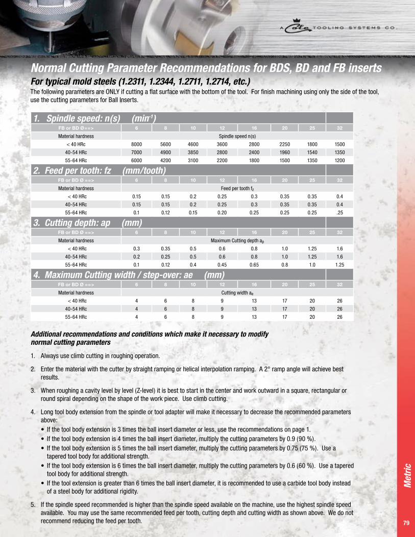
1. Spindle speed: n(s) (min-1)FB or BD Ø==> 6 8 10 12 16 20 25 32
Material hardness Spindle speed n(s)
< 40 HRc 8000 5600 4600 3600 2800 2250 1800 1500
40-54 HRc 7000 4900 3850 2800 2400 1960 1540 1350
55-64 HRc 6000 4200 3100 2200 1800 1500 1350 1200
2. Feed per tooth: fz (mm/tooth)FB or BD Ø ==> 6 8 10 12 16 20 25 32
Material hardness Feed per tooth fz < 40 HRc 0.15 0.15 0.2 0.25 0.3 0.35 0.35 0.4
40-54 HRc 0.15 0.15 0.2 0.25 0.3 0.35 0.35 0.4
55-64 HRc 0.1 0.12 0.15 0.20 0.25 0.25 0.25 .25
3. Cutting depth: ap (mm)FB or BD Ø ==> 6 8 10 12 16 20 25 32
Material hardness Maximum Cutting depth ap
< 40 HRc 0.3 0.35 0.5 0.6 0.8 1.0 1.25 1.6
40-54 HRc 0.2 0.25 0.5 0.6 0.8 1.0 1.25 1.6
55-64 HRc 0.1 0.12 0.4 0.45 0.65 0.8 1.0 1.25
4. Maximum Cutting width / step-over: ae (mm)FB or BD Ø ==> 6 8 10 12 16 20 25 32
Material hardness Cutting width ae
< 40 HRc 4 6 8 9 13 17 20 26
40-54 HRc 4 6 8 9 13 17 20 26
55-64 HRc 4 6 8 9 13 17 20 26
Normal Cutting Parameter Recommendations for BDS, BD and FB insertsFor typical mold steels (1.2311, 1.2344, 1.2711, 1.2714, etc.) The following parameters are ONLY if cutting a flat surface with the bottom of the tool. For finish machining using only the side of the tool, use the cutting parameters for Ball Inserts.
Additional recommendations and conditions which make it necessary to modify normal cutting parameters 1. Always use climb cutting in roughing operation.
2. Enter the material with the cutter by straight ramping or helical interpolation ramping. A 2° ramp angle will achieve best results.
3. When roughing a cavity level by level (Z-level) it is best to start in the center and work outward in a square, rectangular or round spiral depending on the shape of the work piece. Use climb cutting.
4. Long tool body extension from the spindle or tool adapter will make it necessary to decrease the recommended parameters above:
• If the tool body extension is 3 times the ball insert diameter or less, use the recommendations on page 1. • If the tool body extension is 4 times the ball insert diameter, multiply the cutting parameters by 0.9 (90 %). • If the tool body extension is 5 times the ball insert diameter, multiply the cutting parameters by 0.75 (75 %). Use a
tapered tool body for additional strength. • If the tool body extension is 6 times the ball insert diameter, multiply the cutting parameters by 0.6 (60 %). Use a tapered
tool body for additional strength. • If the tool extension is greater than 6 times the ball insert diameter, it is recommended to use a carbide tool body instead
of a steel body for additional rigidity.
5. If the spindle speed recommended is higher than the spindle speed available on the machine, use the highest spindle speed available. You may use the same recommended feed per tooth, cutting depth and cutting width as shown above. We do not recommend reducing the feed per tooth.

80
Copy Milling Program ToolsMillstar face mills are equally useful on newer high velocity machines
and older slower equipment and will optimize milling performance
of all your machine tools. The hardened tool bodies can be run at
aggressive spindle speed and feed rates, when used with Millstar’s
precision ground, strong and thick, round inserts with proven hard,
high performance TLN and HSN tool coatings.
The tools provide for precision finish results, minimal tool deflection
and run-out. Excellent milling results can be achieved in roughing,
semi finishing and fine finishing in Z-level, profiling or raster cuts, as
well as in linear or circular interpolation milling or ramping.
The tools may be used with coolant, but we recommend dry, mist
or MQL (minimum quantity lubrication) milling with strong air blast
when high speed or hard machining steel, particularly in the higher
hardness range (> 45HRc / 425 HBN).
Copy
Mill
ing
Prog
ram
Too
ls

P a g e 8 1
Met
ric
81
Copy Milling Program Tool ContentsFM Style 1 Toroid Cylindrical End Milling Cutter 82
FM Style 2 Toroid Taper End Milling Cutter 82
FMA Arbor Style Milling Cutter 82
Insert Data 83
Cutting Parameters 83
Sect
ion
Cont
ents
ShankMeasurement System
Denotes Copy Milling Cutter
Denotes Diameter Size
Denotes Number of
FlutesDenotes Tool Cutter Length
Denotes Tool Diameter Shank
Imperial FM 1000 / 2 - 6.0 - 1000Metric FM 25 / 2 - 180 - 25
Milling Cutters Identification SystemArborMeasurement System
Denotes Copy Milling Arbor
StyleDenotes
Diameter Size
Denotes Number of
Flutes
Imperial FMA 2000 / 5Metric FMA 63 / 5

Met
ric
82
FM •
FM
A
D2
L1
D1
S2
S1
D
L2
D2
L1
D1
S2L2
S1
D
Toroid Taper End Milling CuttersToroid Cylindrical End Milling Cutters
Tool Ordering Number
Dimensions
Insert ScrewFace Clamp
Screw Key Insert CodeØD ØD1 ØD2 L1 L2 Z
FM-25/2-180-25 25 25 23 30 180 2 FMIS-1 FMIS-2 T15 FMI-12T3
FM-32/2-180-32-16 32 32 29 100 180 2 FMIS-6 FMIS-6FMIW-6
T20 FMI-1604
FM-32/3-180-25 32 25 24 42 180 3 FMIS-1 FMIS-2 T15 FMI-12T3 FMIR-12T3
FM-32/3-180-32 32 32 29 70 180 3 FMIS-1 FMIS-2 T15 FMI-12T3 FMIR-12T3
FM-32/4-180-32-10 32 32 31 42 180 4 FMIS-1 NA T15 FMI-1003
FM-40/3-180-32-16 40 32 29 NA 180 3 FMIS-6 FMIS-6 FMIW-6
T20 FMI-1604
FM-40/4-180-32 40 32 31 42 180 4 FMIS-1 FMIS-2 T15 FMI-12T3 FMIR-12T3
FM-42/4-180-32 42 32 31 42 180 4 FMIS-1 FMIS-2 T15 FMI-12T3 FMIR-12T3
S1
S2
DD
1
2
Key Width
L2
D
Arbor Style Milling CuttersTool Ordering
Number
DimensionsArbor Screw
Insert Screw S1
Face Clamp Screw S2 Key
Insert CodeØD ØD1 L2 Z Key Width D2
FMA-50/5 50 40 50 5 10,4 22 10mm FMIS-1 FMIS-2 T15 FMI-12T3 FMIR-12T3
FMA-52/7-10 52 40 50 7 10,4 22 10mm FMIS-1 NA T15 FMI-1003
FMA-52/5 52 40 50 5 10,4 22 10mm FMIS-1 FMIS-2 T15 FMI-12T3 FMIR-12T3
FMA-52/4-16 52 40 50 4 10,4 22 10mm FMIS-6 FMIS-6FMIW-6
T20 FMI-1604
FMA-63/5 63 40 50 5 12,4 22 12mm FMIS-1 FMIS-2 T15 FMI-12T3 FMIR-12T3
FMA-63/5-16 63 40 50 5 12,4 27 12mm FMIS-6 FMIS-2 T20 FMI-1604
FMA-100/7-16 100 84 55 7 14,4 32 32mm FMIS-6 FMIS-6 FMIW-6
T20 FMI-1604
Copy Milling Program Tools

P a g e 8 3
Met
ric
83
FMI •
Cut
ting
Cond
ition
s
SD15°
D1
Insert DataTool Ordering
Number
Dimensions
HSN TLND S D1
FMI-1003 10 3,18 3,88 • •
FMI-12T3 12 3,97 3,9 • •
FMIR-12T3 12 3,97 3,9 • •
FMI-1604 16 4,77 5,2 • •
Cutting Conditions: Recommended Cutting Speed And ApWorking Material Hardness Insert
Type GradeVc
m/minAp Max
RoughingAp Max Medium
Ap Max Light
Low Alloy Steel (1.7225)
200-280HB FMI HSN, TLN 130-200 2,5-4,5 1,0-2,5 0,1-1,0
Alloy & Die Steel (1.2311, P20, DME2/3/5) 32-42HRC FMI HSN, TLN 100-150 2,5-4,0 1,0-2,5 0,1-1,0
Tool Steel (1.2344, 1.2379) 42-52HRC FMI HSN, TLN 80-100 2,0-3,5 1,0-2,5 0,1-1,0
Stainless Steel (1.4301, 1.4401)
200-350HB FMIR HSN, TLN 120-170 2,5-4,0 1,0-2,5 0,1-1,0
Gray Cast Iron (GG25-GG30)
160-260HB FMIR HSN, TLN 140-190 2,5-4,0 1,0-2,5 0,1-1,0
Nodular Cast Iron (GGG60-GGG70)
180-300HB FMIR HSN, TLN 120-170 2,5-4,0 1,0-2,5 0,1-1,0
Copper Alloy 80-150HB FMIR TLN 350 2,5-4,5 1,0-2,5 0,1-1,0
Aluminum Alloys 30-120HB FMIR TLN 400 2,5-5,0 1,0-2,5 0,1-1,0
Ni & Co Based Alloy 250-320HB FMIR HSN, TLN 30-60 2,0-3,0 1,0-2,5 0,1-1,0
Titanium Alloy (Annealed) <350HB FMIR HSN, TLN 50-70 2,0-3,0 1,0-2,5 0,1-1,0
Cutting Conditions: Recommended Feed fz (mm/tooth)Operation
Ap
IC 0,3 0,5 0,7 0,8 1 1,2 2 3 4 5 6 8
Light
10 0,3 0,23 0,2 0,18 0,15 0 0 0 0 0 0 0
12 0,38 0,3 0,25 0,23 0,21 0,18 0 0 0 0 0 0
16 0,45 0,35 0,3 0,27 0,23 0,21 0,18 0 0 0 0 0
Rough
10 0 0 0 0 0,32 0,29 0,22 0,18 0,16 0,14 0 0
12 0 0 0 0 0,42 0,38 0,3 0,28 0,24 0,20 0,18 0,16
16 0 0 0 0 0,50 0,47 0,36 0,3 0,27 0,25 0,34 0,23
The “fz” indicated above is for an overhang of 3xD. The values are calculated based on the recommended thickness of the chip “hm”. LIGHT: Ae up to 25% of the Diameter of the Tool “D”.ROUGH: Ae up to 75% of the Diameter of the Tool “D”.
Working Diameter (Dw )
In order to compute the RPM value of the spindle it is necessary to determine the Dw which is the effective engaged tool diameter. The Dw depends on the geometry of the inserts (ball nose or toroid) and of the relative position of the tool against the working piece surface. A formula is presented.
Copy Milling Program Tools
FMIR
Chipbreaker Style
FMI
Non-Chipbreaker Style

Met
ric
84
InsertsMillstar Insert Number Corner Radius Use
APHT-1003-AL 0.8 Aluminum
APHT-1604-AL 0.8 Aluminum
APKT-1003-TLN or HSN 0.4 Steel
APKT-1003-TCT 0.4 Steel
APKT-1604-TCT 0.8 Steel
APKT-1604-TLN or HSN 0.8 Steel
APMT-1604-12-TLN 1.2 Steel
APMT-1604-16-TLN 1.6 Steel
APMT-1604-24-TLN 2.4 Steel
APMT-1604-32-TLN 3.2 Steel
APMT-1604-40-TLN 4 Steel
APMT-1604-48-TLN 4.8 Steel
APMT-1604-64-TLN 6.4 Steel
Bodies for 1003 InsertMillstar Part Number Diameter Shank
Diameter Overall Length Effective Length
No. of Flutes Insert size Screw Torx
DSKI-10-110-16 10 16 110 25 1 1003 1425 T07
DSKI-12-110-16 12 16 110 25 1 1003 1425 T07
DSKI-16-110-20 16 20 110 25 2 1003 1425 T07
DSKI-16-175-20 16 20 175 25 2 1003 1425 T07
DSKI-20-125-20 20 20 125 30 3 1003 1225 T07
DSKI-20-200-20 20 20 200 30 3 1003 1225 T07
DSKI-25-125-25 25 25 125 30 4 1003 1225 T07
APKT Series, Inserts and Bodies
Bodies for 1604 InsertMillstar Part Number Diameter Shank
Diameter Overall Length Effective Length
No. of Flutes Insert size Screw Torx
DSMI-20-100-20 20 20 100 30 1 1604 1440 T15
DSMI-20-200-20 20 20 200 35 1 1604 1440 T15
DSMI-25-100-25 25 25 100 30 2 1604 1440 T15
DSMI-25-200-25 25 25 200 35 2 1604 1440 T15
DSMI-32-110-32 32 32 110 35 3 1604 1240 T15
DSMI-32-250-32 32 32 250 35 3 1604 1240 T15
DSMI-40-110-32 40 32 110 35 4 1604 1240 T15
DSMI-40-250-32 40 32 250 35 4 1604 1240 T15
APKT
Ser
ies,
Inse
rts
and
Bodi
es
DSKI Bodies for 1003 Insert
DSMI Bodies for 1604 Insert

P a g e 8 5
Met
ric
85
Arbor Style Holders for 1003 InsertMillstar Part Number Diameter Height Keyway Bore No. of
Flutes Insert size Screw Torx
DSSA-32/5 32 40 8,4 16 5 1003 1225 T07
DSSA-40/6 40 40 8,4 16 6 1003 1225 T07
DSSA-50/7 50 40 10,4 22 7 1003 1225 T07
DSSA-63/9 63 50 10,4 22 9 1003 1225 T07
Screw On Heads for 1003 InsertMillstar Part Number Diameter Length Thread Pilot
DiameterNo. of Flutes Insert size Screw Torx
DSSC-16/2 16 23 M8 8,5 2 1003 1425 T07
DSSC-20/3 20 30 M10 10,5 3 1003 1225 T07
DSSC-25/3 25 35 M12 12,5 3 1003 1425 T07
Screw On Heads for 1604 InsertMillstar Part Number Diameter Length Thread Pilot
DiameterNo. of Flutes Insert size Screw Torx
DSMC-25/2 25 35 M12 12,5 2 1604 1440 T15
DSMC-32/3 32 43 M12 17 3 1604 1240 T15
APKT
Ser
ies,
Inse
rts
and
Bodi
es
Arbor Style Holders for 1604 InsertMillstar Part Number Diameter Height Keyway Bore No. of
Flutes Insert size Screw Torx
DSMA-40/4 40 40 8,4 16 4 1604 1240 T15
DSMA-50/5 50 40 10,4 22 5 1604 1240 T15
DSMA-63/6 63 50 10,4 27 6 1604 1240 T15
DSMA-80/7 80 50 12,4 27 7 1604 1240 T15
DSMA-100/8 100 50 14,4 32 8 1604 1240 T15
DSMA-125/8 120 63 16,4 40 8 1604 1240 T15
DSMA-160/9 160 63 16,4 40 9 1604 1240 T15

Met
ric
86
Inde
xabl
e M
illin
g Pr
ogra
m T
ools
for A
lum
inum
Allo
ys
Milling Cutters Identification SystemModular
Measurement System
Denotes Cutter forNon-Ferrous
Metals & Plastics
SOC = Screw-On Cutter with Side ClearanceSON = Screw-on Cutter with no Side ClearanceSMC =Shell Milling Cutter with Side Clearance
SMN = Shell Milling Cutter with no Side Clearance
Denotes Diameter
Size
Denotes Number of
Flutes
Metric A SOC 32 / 3
Indexable Milling Program Tools for Aluminum Alloys ContentsASOC Modular Screw-on Heads
With Side Clearance87
ØD Ød1M
93˚
ASON Modular Screw-on HeadsWith No Side Clearance
87ØD Ød1M
90 ˚
ASMC Shell Milling Cutters WithSide Clearance
87øD ØD1
93˚
ASMN Shell Milling Cutter WithNo Side Clearance
88øD ØD1
90˚
AEMC End Milling Cutter WithSide Clearance
88ØD
Ødh6
93˚L3
L
D1
AEMN End Milling Cutter WithNo Side Clearance
88ØD
Ødh6
90˚
D1
L3L
Insert Data
89 r
35˚ (l)s
7˚
d
Cutting Conditions 89
Indexable Milling Program Tools for Aluminum Alloys
ShankMeasurement System
Denotes Cutter for Non-Ferrous
Metals & PlasticsEMC = End Milling
Shank CutterDenotes
Diameter Size
Denotes Tool Cutter
LengthDenotes Tool
Diameter Shank
Metric A EMC 42 - 220 - 25Metric A EMN 42 - 220 - 25

P a g e 8 7
Met
ric
87
ØD Ød1M
93˚
ASOC Modular Screw-On HeadsTool Ordering
Number
Dimensions (mm) Use with
RPM MaxØD L Ød1 M Z Screw Key Inserts
ASOC-25/3 25 50 21 M12 3 AIS-1 T7 VCGT-110308 30000
ASOC-32/3 32 50 29 M16 3 AIS-2 T15 VCGT-160412 28000
ASOC-42/3 42 50 29 M16 3 AI-3 T20 VCGT-220530 24000
øD ØD1
93˚
ASMC Shell Milling CuttersTool Ordering
Number
Dimensions (mm) Use with
RPM MaxØD L ØD1 Key Width Z Screw Key Inserts
ASMC-50/3 50 55 22 10,4 3 AIS-2 T15 VCGT-160412 23000
ASMC-63/4 63 60 22 10,4 4 AIS-2 T15 VCGT-160412 20000
ASMC-80/4 80 60 27 12,4 4 AIS-3 T20 VCGT-220530 18000
ASOC
• A
SON
• AS
MC
ØD Ød1M
90 ˚
ASON Modular Screw-On HeadsTool Ordering
Number
Dimensions (mm) Use with
RPM MaxØD L Ød1 M Z Screw Key Inserts
ASON-25/2 25 35 18 M10 2 AIS-1 T7 VCGT-110308 30000
ASON-25/3 25 50 21 M12 3 AIS-1 T7 VCGT-110308 30000
ASON-32/3 32 50 29 M16 3 AIS-2 T15 VCGT-160412 24000
ASON-42/3 42 50 29 M16 3 AIS-3 T20 VCGT-220530 24000

P a g e 8 8
Inch
88
Met
ric
88
øD ØD1
90˚
ASMN Shell Milling CuttersTool Ordering
Number
Dimensions (mm) Use with
RPM MaxØD L ØD1 Key Width L2 Z Screw Key Inserts
ASMN-42/3 42 55 16 8,4 15 3 AIS-3 T20 VCGT-220530 24000
ASMN-50/3 50 55 22 10,4 13 3 AIS-2 T15 VCGT-160412 23000
ASMN-52/3 52 55 22 10,4 15 3 AIS-3 T20 VCGT-220530 22000
ASMN-63/4 63 60 22 10,4 13 4 AIS-2 T15 VCGT-160412 20000
ASMN-66/4 66 60 27 10,4 15 4 AIS-3 T20 VCGT-220530 19000
ASMN-80/5 80 60 27 12,4 15 5 AIS-3 T20 VCGT-220530 18000
ASMN-100/5 100 65 32 14,4 15 5 AIS-3 T20 VCGT-220530 16000
ØDØdh6
93˚L3
L
D1
AEMC End Milling CuttersTool Ordering
Number
Dimensions (mm) Use with
RPM MaxØD L L1 D1 L3 Z Screw Key Inserts
AEMC-25/3 25 140 10 20 40 3 AIS-1 T7 VCGT-110308 30000
AEMC-32/3 32 140 13,5 25 50 3 AIS-2 T15 VCGT-160412 28000
AEMC-42/3 42 140 15 32 50 3 AIS-3 T20 VCGT-220530 24000
Indexable Milling Program Tools for Aluminum Alloys
ØDØdh6
90˚
D1
L3L
AEMN End Milling CuttersTool Ordering
Number
Dimensions (mm) Use with
RPM MaxØD L L1 D1 L3 Z Screw Key Inserts
AEMN-20/2-L100 20 100 10 18 30 2 AIS-1 T7 VCGT-110308 30000
AEMN-20/2-L200 20 200 10 18 30 2 AIS-1 T7 VCGT-110308 26000
AEMN-25/3-L140 25 140 10 20 40 3 AIS-1 T7 VCGT-110308 30000
AEMN-25/3-L240 25 240 10 20 40 3 AIS-1 T7 VCGT-110308 26000
AEMN-32/3-L140 32 140 13 25 50 3 AIS-2 T15 VCGT-160412 28000
AEMN-32/3-L240 32 240 13 25 50 3 AIS-2 T15 VCGT-160412 24000
AEMN-42/3-L140 42 140 15 32 50 3 AIS-3 T20 VCGT-220530 24000
AEMN-42/3-L240 42 240 15 32 50 3 AIS-3 T20 VCGT-220530 20000
ASM
N •
AEM
C •
AEM
N

P a g e 8 9
Met
ric
8989
Met
ric
r
35˚ (l)s
7˚
d
Insert DataTool Ordering
Number
Dimensions
l s d r Screw
VCGT-110308 11 3.18 2.8 0.8 AIS-1
VCGT-160412 16.6 4.76 4.4 1.2 AIS-2
VCGT-220530 22 5.56 5.5 3 AIS-3
Cutting Conditions: Recommended Cutting Speed
Alloy Group
Rm(Mpa)
Roughing Finishing
SpeedVc(m/min)
FeedFz(mm/tooth)
D.O.C.Ap(m/min)
SpeedVc(m/min)
FeedFz(mm/tooth)
D.O.C.Ap(m/min)
Min Max Min Max Max Min Max Min Max Max
AL Alloy <280 600 2000 0,2 0,4 10 600 2000 0,15 0,2 10
Al-Cu 300-460 400 2000 0,25 0,3 10 400 2500 0,15 0,25 10
Al-Mg-Si 200-400 400 2000 10 400 2500 10
Al-Zn 400-600 400 2000 0,25 0,35 10 400 3000 0,15 0,25 10
Al-Si <12%Si 350-380 200 800 0,2 0,25 10 200 1000 0,15 0,2 10
Cupper alloy 400 500 0,2 10 400 500 0,2 10
Mg. alloys 400 450 0,2 10 400 450 0,2 10
Thermoplastics 300 350 0,15 10 300 350 0,15 10
Duro-plastics 180 200 0,15 10 180 200 0,15 10
Inse
rt D
ata
• Cu
ttin
g Co
nditi
ons

P a g e 9 0
Met
ric
9090
High Feed Indexable Milling Program Tools With new five- and six-axis CNC grinding technology, Millstar has been
able to create some of the most sophisticated and complex geometries in
use today. With this increase in grinding technology, high-feed tooling has
been reborn. The definition of high-feed geometry is producing a positive
cutting edge out of a series of continuous radii with no tangent point to
induce wear. The geometry must allow the chip to flow up and out of the
cut quickly and smoothly. This cutting motion allows the use of heavy chip
loads to achieve very high feed rates.
High
Fee
d In
dexa
ble
Mill
ing
Prog
ram
Too
ls

P a g e 9 1
Met
ric
Met
ric
91
High Feed Indexable Milling Program Tool ContentsHFSC Modular Screw-on Heads 92
HFA Shell Milling Cutters 92
HFSS End Milling Cutters 92
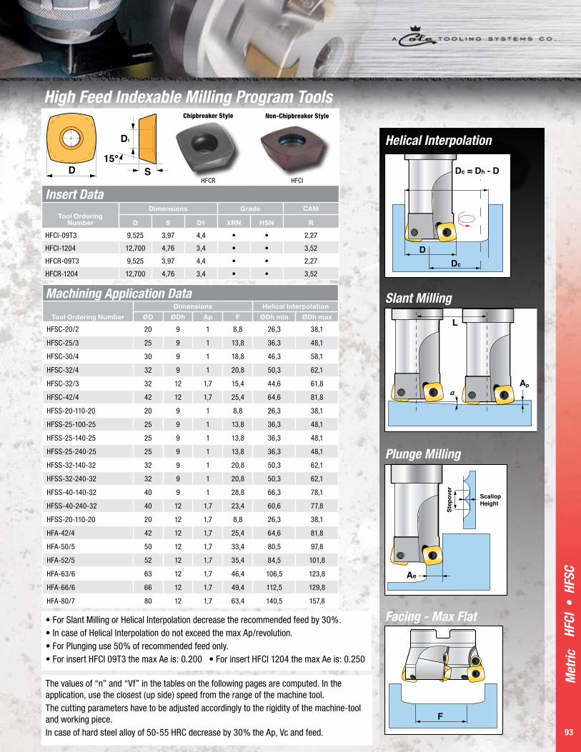
Insert Data 93
Cutting Conditions Data
94-98
Sect
ion
Cont
ents
ShankMeasurement System
Denotes High Feed Cutter
Denotes Shank Cutter
Denotes Diameter Size
Denotes Tool Cutter
LengthDenotes Tool
Diameter Shank
Imperial HF SS 1000 - 5.5 - 1000Metric HF SS 25 - 140 - 25
Milling Cutters Identification SystemModularMeasurement System
Denotes High Feed Cutter
SC = Screw-on CutterA = Shell Cutter
Denotes Diameter Size
Denotes Number of Flutes
Imperial HF SC 1000 / 3Metric HF SC 25 / 3

Met
ric
92
HFSC
• H
FA •
HFS
S
HFSC - Modular Screw-On HeadsTool Ordering
Number
DimensionsThread
G1 Screw Clamp KeyUse with Inserts CAM RØD L1 L2 D2 Z
HFSC-20/2 20 31 49 10,5 2 M10 HFIS 1 - T8 HFCI-09T3 2,27
HFSC-25/3 25 32 54 12,5 3 M12 HFIS 1 - T8 HFCI-09T3 2,27
HFSC-30/4 30 40 63 16,5 4 M16 HFIS 1 - T8 HFCI-09T3 2,27
HFSC-32/4 32 40 63 16,5 4 M16 HFIS 1 - T8 HFCI-09T3 2,27
HFSC-32/3 32 40 63 16,5 3 M16 HFIS 2 HFIC-1 T15 HFCI-1204 3,52
HFSC-42/4 42 40 63 16,5 4 M16 HFIS 2 HFIC-1 T15 HFCI-1204 3,52
S2
D1
S2
C1
HFA - Shell Milling Cutters
Tool Ordering Number
DimensionsScrew
S1Screw
S2Clamp
C1 KeyUse with Inserts CAM RØD ØD1 L1 L2 Z
HFA-42/4 42 16 8,4 40 4 HFIS-2 HFIS-2 HFIC-1 T15 HFCI-1204 3,52
HFA-50/5 50 22 10,4 40 5 HFIS-2 HFIS-2 HFIC-1 T15 HFCI-1204 3,52
HFA-52/5 52 22 10,4 50 5 HFIS-2 HFIS-2 HFIC-1 T15 HFCI-1204 3,52
HFA-63/6 63 27 12,4 50 6 HFIS-2 HFIS-2 HFIC-1 T15 HFCI-1204 3,52
HFA-66/6 66 27 12,4 50 6 HFIS-2 HFIS-2 HFIC-1 T15 HFCI-1204 3,52
HFA-80/7 80 27 12,4 50 7 HFIS-2 HFIS-2 HFIC-1 T15 HFCI-1204 3,52
HFA-100/8 100 32 14,4 50 8 HFIS-2 HFIS-2 HFIC-1 T15 HFCI-1204 3,52
HFSS - End Milling Cutters
Tool Ordering Number
Dimensions
ScrewClamp
C1 KeyUse with Inserts CAM RØD ØD1 L1 L2 Z
HFSS-20-110-20 20 20 30 110 2 HFIS-1 - T8 HFCI-09T3 2,27
HFSS-25-100-25 25 25 30 100 3 HFIS-1 - T8 HFCI-09T3 2,27
HFSS-25-140-25 25 25 40 140 3 HFIS-1 - T8 HFCI-09T3 2,27
HFSS-25-240-25 25 25 40 240 3 HFIS-1 - T8 HFCI-09T3 2,27
HFSS-32-140-32 32 32 40 140 4 HFIS-1 - T8 HFCI-09T3 2,27
HFSS-32-240-32 32 32 40 240 4 HFIS-1 - T8 HFCI-09T3 2,27
HFSS-40-140-32 40 32 - 140 4 HFIS-2 HFIC-1 T15 HFCI-1204 3,52
HFSS-40-240-32 40 32 - 240 4 HFIS-2 HFIC-1 T15 HFCI-1204 3,52
High Feed Indexable Milling Program Tools
P a g e 9 3
Met
ric
93
HFCI
• H
FSC
Machining Application Data
Tool Ordering Number
Dimensions Helical Interpolation
ØD ØDh Ap F ØDh min ØDh max
HFSC-20/2 20 9 1 8,8 26,3 38,1
HFSC-25/3 25 9 1 13,8 36,3 48,1
HFSC-30/4 30 9 1 18,8 46,3 58,1
HFSC-32/4 32 9 1 20,8 50,3 62,1
HFSC-32/3 32 12 1,7 15,4 44,6 61,8
HFSC-42/4 42 12 1,7 25,4 64,6 81,8
HFSS-20-110-20 20 9 1 8,8 26,3 38,1
HFSS-25-100-25 25 9 1 13,8 36,3 48,1
HFSS-25-140-25 25 9 1 13,8 36,3 48,1
HFSS-25-240-25 25 9 1 13,8 36,3 48,1
HFSS-32-140-32 32 9 1 20,8 50,3 62,1
HFSS-32-240-32 32 9 1 20,8 50,3 62,1
HFSS-40-140-32 40 9 1 28,8 66,3 78,1
HFSS-40-240-32 40 12 1,7 23,4 60,6 77,8
HFSS-20-110-20 20 12 1,7 8,8 26,3 38,1
HFA-42/4 42 12 1,7 25,4 64,6 81,8
HFA-50/5 50 12 1,7 33,4 80,5 97,8
HFA-52/5 52 12 1,7 35,4 84,5 101,8
HFA-63/6 63 12 1,7 46,4 106,5 123,8
HFA-66/6 66 12 1,7 49,4 112,5 129,8
HFA-80/7 80 12 1,7 63,4 140,5 157,8
Insert DataTool Ordering
Number
Dimensions Grade CAM
D S D1 XRN HSN R
HFCI-09T3 9,525 3,97 4,4 • • 2,27
HFCI-1204 12,700 4,76 3,4 • • 3,52
HFCR-09T3 9,525 3,97 4,4 • • 2,27
HFCR-1204 12,700 4,76 3,4 • • 3,52
The values of “n” and “Vf” in the tables on the following pages are computed. In the application, use the closest (up side) speed from the range of the machine tool.The cutting parameters have to be adjusted accordingly to the rigidity of the machine-tool and working piece.In case of hard steel alloy of 50-55 HRC decrease by 30% the Ap, Vc and feed.
High Feed Indexable Milling Program Tools
• For Slant Milling or Helical Interpolation decrease the recommended feed by 30%.• In case of Helical Interpolation do not exceed the max Ap/revolution.• For Plunging use 50% of recommended feed only. • For insert HFCI 09T3 the max Ae is: 0.200 • For insert HFCI 1204 the max Ae is: 0.250
Helical Interpolation
Slant Milling
Plunge Milling
Facing - Max Flat
HFCR
Chipbreaker Style
HFCI
Non-Chipbreaker Style

Met
ric
94
HF C
uttin
g Co
nditi
ons
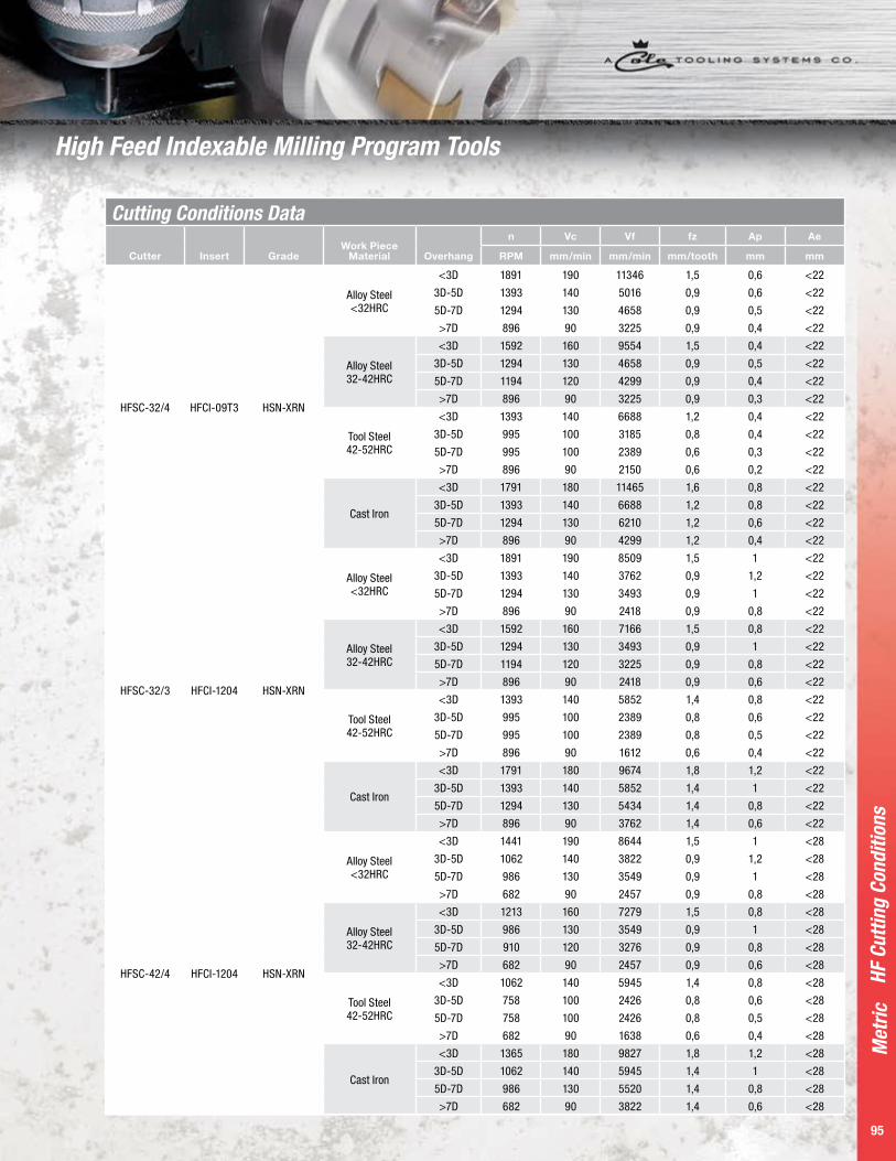
Cutting Conditions Data
Cutter Insert GradeWork Piece
Material Overhang
n Vc Vf fz Ap Ae
RPM mm/min mm/min mm/tooth mm mm
HFSC-20/2 HFCI-09T3 HSN-XRN
Alloy Steel <32HRC
<3D 3025 190 8471 1,4 0,6 <15
3D-5D 2229 140 3567 0,8 0,6 <15
5D-7D 2070 130 3312 0,8 0,5 <15
>7D 1433 90 2293 0,8 0,4 <15
Tool Steel 32-42HRC
<3D 2548 160 7134 1,4 0,4 <15
3D-5D 2070 130 3312 0,8 0,5 <15
5D-7D 1911 120 3057 0,8 0,4 <15
>7D 1433 90 2293 0,8 0,3 <15
Tool Steel 42-52HRC
<3D 2229 140 5350 1,2 0,4 <15
3D-5D 1592 100 2548 0,8 0,4 <15
5D-7D 1592 100 2548 0,8 0,3 <15
>7D 1433 90 1720 0,6 0,2 <15
Cast Iron
<3D 2866 180 9172 1,6 0,8 <15
3D-5D 2229 140 5350 1,2 0,8 <15
5D-7D 2070 130 4968 1,2 0,6 <15
>7D 1433 90 3439 1,2 0,5 <15
HFSC 25/3 HFCI-09T3 HSN-XRN
Alloy Steel <32HRC
<3D 2420 190 11618 1,6 0,6 <20
3D-5D 1783 140 5350 1 0,6 <20
5D-7D 1656 130 4968 1 0,5 <20
>7D 1146 90 3439 1 0,4 <20
Alloy Steel 32-42HRC
<3D 2038 160 9783 1,6 0,4 <20
3D-5D 1656 130 4968 1 0,5 <20
5D-7D 1529 120 4586 1 0,4 <20
>7D 1146 90 3439 1 0,3 <20
Tool Steel 42-52HRC
<3D 1783 140 7490 1,4 0,4 <20
3D-5D 1274 100 3057 0,8 0,4 <20
5D-7D 1274 100 3057 0,8 0,3 <20
>7D 1146 90 2064 0,6 0,2 <20
Cast Iron
<3D 2293 180 11006 1,6 0,8 <20
3D-5D 1783 140 6420 1,2 0,8 <20
5D-7D 1656 130 5962 1,2 0,6 <20
>7D 1146 90 4127 1,2 0,5 <20
HFSC-30/4 HFCI-09T3 HSN-XRN
Alloy Steel <32HRC
<3D 2017 190 12102 1,5 0,6 <21
3D-5D 1486 140 5350 0,9 0,6 <21
5D-7D 1380 130 4968 0,9 0,5 <21
>7D 955 90 3439 0,9 0,4 <21
Alloy Steel 32-42HRC
<3D 1699 160 10191 15 0,4 <21
3D-5D 1380 130 4968 0,9 0,5 <21
5D-7D 1274 120 4586 0,9 0,4 <21
>7D 955 90 3439 0,9 0,3 <21
Tool Steel 42-52HRC
<3D 1486 140 7134 1,2 0,4 <21
3D-5D 1062 100 3397 0,8 0,4 <21
5D-7D 1062 100 2548 0,6 0,3 <21
>7D 955 90 2293 0,6 0,2 <21
Cast Iron
<3D 1911 180 12229 1,6 0,8 <21
3D-5D 1486 140 7134 1,2 0,8 <21
5D-7D 1380 130 6624 1,2 0,6 <21
>7D 955 90 4586 1,2 0,4 <21
High Feed Indexable Milling Program Tools
P a g e 9 5
Met
ric
95
HF C
uttin
g Co
nditi
ons
Cutting Conditions Data
Cutter Insert GradeWork Piece
Material Overhang
n Vc Vf fz Ap Ae
RPM mm/min mm/min mm/tooth mm mm
HFSC-32/4 HFCI-09T3 HSN-XRN
Alloy Steel <32HRC
<3D 1891 190 11346 1,5 0,6 <22
3D-5D 1393 140 5016 0,9 0,6 <22
5D-7D 1294 130 4658 0,9 0,5 <22
>7D 896 90 3225 0,9 0,4 <22
Alloy Steel 32-42HRC
<3D 1592 160 9554 1,5 0,4 <22
3D-5D 1294 130 4658 0,9 0,5 <22
5D-7D 1194 120 4299 0,9 0,4 <22
>7D 896 90 3225 0,9 0,3 <22
Tool Steel 42-52HRC
<3D 1393 140 6688 1,2 0,4 <22
3D-5D 995 100 3185 0,8 0,4 <22
5D-7D 995 100 2389 0,6 0,3 <22
>7D 896 90 2150 0,6 0,2 <22
Cast Iron
<3D 1791 180 11465 1,6 0,8 <22
3D-5D 1393 140 6688 1,2 0,8 <22
5D-7D 1294 130 6210 1,2 0,6 <22
>7D 896 90 4299 1,2 0,4 <22
HFSC-32/3 HFCI-1204 HSN-XRN
Alloy Steel <32HRC
<3D 1891 190 8509 1,5 1 <22
3D-5D 1393 140 3762 0,9 1,2 <22
5D-7D 1294 130 3493 0,9 1 <22
>7D 896 90 2418 0,9 0,8 <22
Alloy Steel 32-42HRC
<3D 1592 160 7166 1,5 0,8 <22
3D-5D 1294 130 3493 0,9 1 <22
5D-7D 1194 120 3225 0,9 0,8 <22
>7D 896 90 2418 0,9 0,6 <22
Tool Steel 42-52HRC
<3D 1393 140 5852 1,4 0,8 <22
3D-5D 995 100 2389 0,8 0,6 <22
5D-7D 995 100 2389 0,8 0,5 <22
>7D 896 90 1612 0,6 0,4 <22
Cast Iron
<3D 1791 180 9674 1,8 1,2 <22
3D-5D 1393 140 5852 1,4 1 <22
5D-7D 1294 130 5434 1,4 0,8 <22
>7D 896 90 3762 1,4 0,6 <22
HFSC-42/4 HFCI-1204 HSN-XRN
Alloy Steel <32HRC
<3D 1441 190 8644 1,5 1 <28
3D-5D 1062 140 3822 0,9 1,2 <28
5D-7D 986 130 3549 0,9 1 <28
>7D 682 90 2457 0,9 0,8 <28
Alloy Steel 32-42HRC
<3D 1213 160 7279 1,5 0,8 <28
3D-5D 986 130 3549 0,9 1 <28
5D-7D 910 120 3276 0,9 0,8 <28
>7D 682 90 2457 0,9 0,6 <28
Tool Steel 42-52HRC
<3D 1062 140 5945 1,4 0,8 <28
3D-5D 758 100 2426 0,8 0,6 <28
5D-7D 758 100 2426 0,8 0,5 <28
>7D 682 90 1638 0,6 0,4 <28
Cast Iron
<3D 1365 180 9827 1,8 1,2 <28
3D-5D 1062 140 5945 1,4 1 <28
5D-7D 986 130 5520 1,4 0,8 <28
>7D 682 90 3822 1,4 0,6 <28
High Feed Indexable Milling Program Tools

Met
ric
96
HF C
uttin
g Co
nditi
ons
Cutting Conditions Data
Cutter Insert GradeWork Piece
Material Overhang
n Vc Vf fz Ap Ae
RPM mm/min mm/min mm/tooth mm mm
HFSS-20-110-20 HFCI-09T3 HSN-XRN
Alloy Steel <32HRC
<3D 3025 190 8471 1,4 0,6 <15
3D-5D 2229 140 3567 0,8 0,6 <15
5D-7D 2070 130 3312 0,8 0,5 <15
>7D 1433 90 2293 0,8 0,4 <15
Tool Steel 32-42HRC
<3D 2548 160 7134 1,4 0,4 <15
3D-5D 2070 130 3312 0,8 0,5 <15
5D-7D 1911 120 3057 0,8 0,4 <15
>7D 1433 90 2293 0,8 0,3 <15
Tool Steel 42-52HRC
<3D 2229 140 5350 1,2 0,4 <15
3D-5D 1592 100 2548 0,8 0,4 <15
5D-7D 1592 100 2548 0,8 0,3 <15
>7D 1433 90 1720 0,6 0,2 <15
Cast Iron
<3D 2866 180 9172 1,6 0,8 <15
3D-5D 2229 140 5350 1,2 0,8 <15
5D-7D 2070 130 4968 1,2 0,6 <15
>7D 1433 90 3439 1,2 0,5 <15
HFSS-25-110-25 HFSS-25-140-25 HFSS-25-240-25
HFCI-09T3 HSN-XRN
Alloy Steel <32HRC
<3D 2420 190 11618 1,6 0,6 <20
3D-5D 1783 140 5350 1 0,6 <20
5D-7D 1656 130 4968 1 0,5 <20
>7D 1146 90 3439 1 0,4 <20
Tool Steel 32-42HRC
<3D 2038 160 9783 1,6 0,4 <20
3D-5D 1656 130 4968 1 0,5 <20
5D-7D 1529 120 4586 1 0,4 <20
>7D 1146 90 3439 1 0,3 <20
Tool Steel 42-52HRC
<3D 1783 140 7490 1,4 0,4 <20
3D-5D 1274 100 3057 0,8 0,4 <20
5D-7D 1274 100 3057 0,8 0,3 <20
>7D 1146 90 2064 0,6 0,2 <20
Cast Iron
<3D 2293 180 11006 1,6 0,8 <20
3D-5D 1783 140 6420 1,2 0,8 <20
5D-7D 1656 130 5962 1,2 0,6 <20
>7D 1146 90 4127 1,2 0,5 <20
HFSS 32-140-32 HFSS-32-240-32 HFCI-09T3 HSN-XRN
Alloy Steel <32HRC
<3D 2017 190 12102 1,5 0,6 <21
3D-5D 1486 140 5350 0,9 0,6 <21
5D-7D 1380 130 4968 0,9 0,5 <21
>7D 896 90 3225 0,9 0,4 <21
Tool Steel 32-42HRC
<3D 1699 160 10191 1,5 0,4 <21
3D-5D 1380 130 4968 0,9 0,5 <21
5D-7D 1274 120 4586 0,9 0,4 <21
>7D 896 90 3225 0,9 0,3 <21
Tool Steel 42-52HRC
<3D 1486 140 7134 1,2 0,4 <21
3D-5D 1062 100 3397 0,8 0,4 <21
5D-7D 1062 100 2548 0,6 0,3 <21
>7D 896 90 2150 0,6 0,2 <21
Cast Iron
<3D 1911 180 12229 1,6 0,8 <21
3D-5D 1486 140 7134 1,2 0,8 <21
5D-7D 1380 130 6624 1,2 0,6 <21
>7D 896 90 4299 1,2 0,4 <21
High Feed Indexable Milling Program Tools

P a g e 9 7
Met
ric
97
HF C
uttin
g Co
nditi
ons
Cutting Conditions Data
Cutter Insert GradeWork Piece
Material Overhang
n Vc Vf fz Ap Ae
RPM mm/min mm/min mm/tooth mm mm
HFSS-40-140-32 HFSS-40-240-32 HFCI-1204 HSN-XRN
Alloy Steel <32HRC
<3D 1441 190 8644 1,5 1 <28
3D-5D 1062 140 3822 0,9 1,2 <28
5D-7D 986 130 3549 0,9 1 <28
>7D 717 90 2580 0,9 0,8 <28
Tool Steel 32-42HRC
<3D 1213 160 7279 1,5 0,8 <28
3D-5D 986 130 3549 0,9 1 <28
5D-7D 910 120 3276 0,9 0,8 <28
>7D 717 90 2580 0,9 0,6 <28
Tool Steel 42-52HRC
<3D 1062 140 5945 1,4 0,8 <28
3D-5D 758 100 2426 0,8 0,6 <28
5D-7D 758 100 2426 0,8 0,5 <28
>7D 717 90 1720 0,6 0,4 <28
Cast Iron
<3D 1365 180 9827 1,8 1,2 <28
3D-5D 1062 140 5945 1,4 1 <28
5D-7D 986 130 5520 1,4 0,8 <28
>7D 717 90 4013 1,4 0,6 <28
HFA-42/4 HFCI-1204 HSN-XRN
Alloy Steel <32HRC
<3D 1441 190 8644 1,5 1 <28
3D-5D 1062 140 3822 0,9 1,2 <28
5D-7D 986 130 3549 0,9 1 <28
>7D 682 90 2457 0,9 0,8 <28
Tool Steel 32-42HRC
<3D 1213 160 7279 1,5 0,8 <28
3D-5D 986 130 3549 0,9 1 <28
5D-7D 910 120 3276 0,9 0,8 <28
>7D 682 90 2457 0,9 0,6 <28
Tool Steel 42-52HRC
<3D 1062 140 5945 1,4 0,8 <28
3D-5D 758 100 2426 0,8 0,6 <28
5D-7D 758 100 2426 0,8 0,5 <28
>7D 682 90 1638 0,6 0,4 <28
Cast Iron
<3D 1365 180 9827 1,8 1,2 <28
3D-5D 1062 140 5945 1,4 1 <28
5D-7D 986 130 5520 1,4 0,8 <28
>7D 682 90 3822 1,4 0,6 <28
HFA-50/5 HFCI-1204 HSN-XRN
Alloy Steel <32HRC
<3D 1210 190 8471 1,4 0,7 <35
3D-5D 892 140 4459 1 1 <35
5D-7D 828 130 4140 1 0,8 <35
>7D 573 90 2293 0,8 0,6 <35
Tool Steel 32-42HRC
<3D 1019 160 6115 1,2 0,6 <35
3D-5D 828 130 4140 1 0,6 <35
5D-7D 764 120 3822 1 0,6 <35
>7D 573 90 2293 0,8 0,4 <35
Tool Steel 42-52HRC
<3D 892 140 5350 1,2 0,6 <35
3D-5D 637 100 2548 0,8 0,5 <35
5D-7D 637 100 2548 0,8 0,4 <35
>7D 573 90 2293 0,8 0,3 <35
Cast Iron
<3D 1146 180 9172 1,6 1 <35
3D-5D 892 140 5350 1,2 0,8 <35
5D-7D 828 130 4968 1,2 0,6 <35
>7D 573 90 3439 1,2 0,4 <35
High Feed Indexable Milling Program Tools

Met
ric
98
HF C
uttin
g Co
nditi
ons
Cutting Conditions Data
Cutter Insert GradeWork Piece
Material Overhang
n Vc Vf fz Ap Ae
RPM mm/min mm/min mm/tooth mm mm
HFA-52/5 HFCI-1204 HSN-XRN
Alloy Steel <32HRC
<3D 1164 190 8146 1,4 0,7 <36
3D-5D 857 140 4287 1 1 <36
5D-7D 796 130 3981 1 0,8 <36
>7D 551 90 2205 0,8 0,6 <36
Tool Steel 32-42HRC
<3D 980 160 5879 1,2 0,6 <36
3D-5D 796 130 3981 1 0,6 <36
5D-7D 735 120 3675 1 0,6 <36
>7D 551 90 2205 0,8 0,4 <36
Tool Steel 42-52HRC
<3D 857 140 5145 1,2 0,6 <36
3D-5D 612 100 2450 0,8 0,5 <36
5D-7D 612 100 2450 0,8 0,4 <36
>7D 551 90 2205 0,8 0,3 <36
Cast Iron
<3D 1102 180 8819 1,6 1 <36
3D-5D 857 140 5145 1,2 0,8 <36
5D-7D 796 130 4777 1,2 0,6 <36
>7D 551 90 3307 1,2 0,4 <36
HFA-63/6 HFCI-1204 HSN-XRN
Alloy Steel <32HRC
<3D 960 190 8068 1,4 0,7 <45
3D-5D 708 140 4246 1 1 <45
5D-7D 657 130 3943 1 0.8 <45
>7D 455 90 2184 0,8 0,6 <45
Tool Steel 32-42HRC
<3D 809 160 5823 1,2 0,6 <45
3D-5D 657 130 3943 1 0,6 <45
5D-7D 607 120 3640 1 0,6 <45
>7D 455 90 2184 0,8 0,4 <45
Tool Steel 42-52HRC
<3D 708 140 5096 1,2 0,6 <45
3D-5D 506 100 2426 0,8 0,5 <45
5D-7D 506 100 2426 0,8 0,4 <45
>7D 455 90 2184 0,8 0,3 <45
Cast Iron
<3D 910 180 8735 1,6 1 <45
3D-5D 708 140 5096 1,2 0,8 <45
5D-7D 657 130 4732 1,2 0,6 <45
>7D 455 90 3276 1,2 0,4 <45
HFA-66/6 HFCI-1204 HSN-XRN
Alloy Steel <32HRC
<3D 917 190 7701 1,4 0,7 <47
3D-5D 676 140 4053 1 1 <47
5D-7D 627 130 3764 1 0,8 <47
>7D 434 90 2085 0,8 0,6 <47
Tool Steel 32-42HRC
<3D 772 160 5559 1,2 0,6 <47
3D-5D 627 130 3764 1 0,6 <47
5D-7D 579 120 3474 1 0,6 <47
>7D 434 90 2085 0,8 0,4 <47
Tool Steel 42-52HRC
<3D 676 140 4864 1,2 0,6 <47
3D-5D 483 100 2316 0,8 0,5 <47
5D-7D 483 100 2316 0,8 0,4 <47
>7D 434 90 2085 0,8 0,3 <47
Cast Iron
<3D 869 180 8338 1,6 1 <47
3D-5D 676 140 4864 1,2 0,8 <47
5D-7D 627 130 4517 1,2 0,6 <47
>7D 434 90 3127 1,2 0,4 <47
High Feed Indexable Milling Program Tools

99
End
Mill
s
High Performance Solid Carbide End MillsMillstar offers a wide variety of Solid Carbide End Mills that are designed for high
performance machining. Our impressive lineup features a large selection of High Feed
Solid Carbide End Mills that achieve the highest performance in the industry. Our End
Mills can be used in a broad spectrum of materials such as hardened steels, soft steels,
titanium, cobalt chrome and many more.

Met
ric
100
BMT 102-104
EMBT 105-107
EMS Square 108
EMB Square–Bullnose 108
BM, BM4T Ball 109
BMS 72 Angle 30˚ 109
TOM Toroid 110
IMB-2-LL Bull Nose Long Length 2 Flute
110
IMB-4-LL Bull Nose Long Length 4 Flute NEW TOOL
110
BMNL Ball–Extended Reach, Taper Nose
111
EMR Square End Bull Nose with Corner Radius, Extended Reach Taper Nose
111
EMS2...LL 2 Flute Long Series – Square
112
EMS4...LL 4 Flute Long Series – Square
112
EMSA 3 Flute – 45˚ 112
BMA 3 Flute – Ball 45˚ 112
BM2 2 Flute – Long Series – Ball
112
BM4 4 Flute – Long Series – Ball
112
EMV4 4 Flute Variable – Square, 45˚ Chamfer
113
BM220 220˚ 2 Flute – Ball 113
EMS2 2 Flute – Square 113
EMS4 4 Flute – Square 113
BMNL Ball Nose Taper Neck
113
HFM4 High Feed Four Flute Solid Carbide
114
HFM6 High Feed with Coolant Through 6 Flute
114
HFM True Radius
High Feed Bullnose Series
114
Cutting Conditions
115
AlumiStar ALP 2
2 Flute Endmill, Aluminum
116
AlumiStar ALP 3
3 Flute Endmill, Aluminum
116
Solid Carbide End Mill Program Tool Contents

P a g e 1 0 1
Met
ric
101101
Solid
Car
bide
End
Mill
s
Solid Carbide End MillsMillstar’s new High Performance and ultra-precise solid carbide end mills were designed
for high speed, high velocity and hard steel milling. Designed with specially selected
premium sub-micron carbide substrate, special tool geometry and proprietary heat-
defying EXALON tool coating, these tools made in the United States, and are competitively
priced. Ideal choices for accurately and aggressively machining products in:
• Mold and die making: injection molds, glass molds, forging dies, extrusion dies.
• Aerospace: engine, landing gear and tail hook components, structural components,
blisks, airfoil machining and forging dies, helicopter rotor components.
• Power generating: turbine blades and other components.
• Medical: hip and knee replacement joints, surgical instruments, medical device molds.
• Automotive: stamping dies, wheel and tire molds, ball joints, cam shaft machining,
racing engine details, bumper and other injection molds, die cast dies, forging dies for
crank and cam shafts, connecting rods, steering knuckles and yokes.
• Consumer products: molds for cake forms and baking dishes, cell phones, lawn
chairs, trash cans, toys, bottles, recyclable cutlery and dishes, jewelry, golf clubs,
safety helmets, computer and accessory housings.
NA Non-coated grade.
XRN Multi-layer hybrid coating of AlCrN. This coating has very good heat resistance and also a low friction coefficient. The XRN coating is designed for use in HSM of un-heat treated softer materials such as Titanium, Inconel, Stainless Steels and other gummy materials that require the use of liquid coolant.
HSN Millstar’s new coating is a multi-layer hybrid Nano coating. This new coating has very good heat resistance and high hardness. The HSN coating is designed for use in HSM of Heat Treated materials up to 72 HRc.
ALTiN-EXALON (TLN) Titanium Aluminum Nitride advanced PVD coating. A special, improved ALTiN coating approaching surface hardness of CBN on a tough substrate. Recommended for tough and hard metal machining applications.
Custom tool coatings for specific applications are available by request.

Met
ric
102
BMT
Solid Carbide End Mill Program Tools
BMT Tool
Ordering No, Cutter Diameter tol. +0 /–0.0004
Effective Length
Shank Diameter
Neck Diameter
Cutting Length
Overall Length
BMT-0,5-HSN-3NL 0,5 3 4 0,47 0,4 45
BMT-0,5-HSN-6NL 0,5 6 4 0,47 0,4 45
BMT-0,5-HSN-8NL 0,5 8 4 0,47 0,4 45
BMT-1,0-HSN-4NL 1 4 4 0,8 0,8 45
BMT-1,0-HSN-6NL 1 6 4 0,8 0,8 45
BMT-1,0-HSN-8NL 1 8 4 0,8 0,8 45
BMT-1,0-HSN-10NL 1 10 4 0,8 0,8 45
BMT-1,0-HSN-12NL 1 12 4 0,8 0,8 45
BMT-1,0-HSN-16NL 1 16 4 0,8 0,8 45
BMT-1,5-HSN-4NL 1,5 4 4 1,44 1,2 45
BMT-1,5-HSN-6NL 1,5 6 4 1,44 1,2 45
BMT-1,5-HSN-8NL 1,5 8 4 1,44 1,2 45
BMT-1,5-HSN-10NL 1,5 10 4 1,44 1,2 45
BMT-1,5-HSN-12NL 1,5 12 4 1,44 1,2 45
BMT-1,5-HSN-16NL 1,5 16 4 1,44 1,2 45
BMT-1,5-HSN-20NL 1,5 20 4 1,44 1,2 45
BMT-2,0-HSN-8NL 2 8 4 1,94 1,6 45
BMT-2,0-HSN-10NL 2 10 4 1,94 1,6 45
BMT-2,0-HSN-12NL 2 12 4 1,94 1,6 45
BMT-2,0-HSN-16NL 2 16 4 1,94 1,6 45
BMT-2,0-HSN-20NL 2 20 4 1,94 1,6 45
BMT-2,0-HSN-25NL 2 25 4 1,94 1,6 45
BMT-2,5-HSN-8NL 2,5 8 4 2,41 2 45
BMT-2,5-HSN-10NL 2,5 10 4 2,41 2 45
BMT-2,5-HSN-12NL 2,5 12 4 2,41 2 45
BMT-2,5-HSN-16NL 2,5 16 4 2,41 2 45
BMT-2,5-HSN-20NL 2,5 20 4 2,41 2 45
BMT-2,5-HSN-25NL 2,5 25 4 2,41 2 45
BMT-2,5-HSN-30NL 2,5 30 4 2,41 2 45
BMT-3,0-HSN-8NL 3 8 6 2,91 2,4 60
BMT-3,0-HSN-10NL 3 10 6 2,91 2,4 60
BMT-3,0-HSN-12NL 3 12 6 2,91 2,4 60
BMT-3,0-HSN-16NL 3 16 6 2,91 2,4 60
BMT-3,0-HSN-20NL 3 20 6 2,91 2,4 75
BMT-3,0-HSN-25NL 3 25 6 2,91 2,4 75
BMT-3,0-HSN-30NL 3 30 6 2,91 2,4 75
BMT-4,0-HSN-16NL 4 15 6 3,91 3,91 75
BMT-4,0-HSN-20NL 4 20 6 3,91 3,91 75
BMT-4,0-HSN-25NL 4 25 6 3,91 3,91 75
BMT-4,0-HSN-30NL 4 30 6 3,91 3,91 75
BMT-4,0-HSN-35NL 4 35 6 3,91 3,91 80

P a g e 1 0 3
Met
ric
103
Cutting Conditions DataWork Piece Material
Carbon Steels, Alloy Steels, (180-250HB)Copper(Cu): N+20% / fz+20%
Tool Steels(25~35HRC)
Mill Dia.Radius Neck
Lengthdoc woc N fz Vf doc woc N fz Vf
mm mm mm rpm mm/tooth mm/min mm mm rpm mm/tooth mm/min
0,5 0,25 4 0,02 0,06 50,000 0,011 1,100 0,018 0,054 50,000 0,001 990
0,5 0,25 6 0,013 0,039 50,000 0,011 1,100 0,012 0,035 40,000 0,001 790
1 0,5 3 0,1 0,3 38,000 0,022 1,670 0,09 0,27 29,000 0,02 1,150
1 0,5 4 0,07 0,21 38,000 0,022 1,670 0,063 0,189 29,000 0,02 1,150
1 0,5 6 0,04 0,12 34,000 0,022 1,500 0,036 0,108 29,000 0,02 1,150
1 0,5 8 0,04 0,12 34,000 0,022 1,500 0,036 0,108 29,000 0,02 1,150
1 0,5 10 0,025 0,075 27,000 0,022 1,190 0,023 0,068 20,000 0,02 790
1 0,5 12 0,025 0,075 27,000 0,022 1,190 0,023 0,068 20,000 0,02 790
1 0,5 16 0,015 0,045 19,000 0,022 840 0,014 0,041 17,000 0,02 680
1 0,5 20 0,01 0,03 19,000 0,022 840 0,009 0,027 17,000 0,02 680
1,2 0,6 8 0,04 0,12 29,000 0,026 1,510 0,036 0,108 21,000 0,023 980
1,2 0,6 12 0,03 0,09 22,000 0,026 1,140 0,027 0,081 17,000 0,023 790
1,4 0,7 8 0,055 0,165 25,000 0,03 1,500 0,05 0,149 18,000 0,027 970
1,4 0,7 16 0,035 0,105 19,000 0,03 1,140 0,032 0,095 14,000 0,027 760
1,5 0,75 8 0,06 0,18 23,000 0,033 1,520 0,054 0,162 17,000 0,03 1,010
1,5 0,75 12 0,06 0,18 23,000 0,033 1,520 0,054 0,162 17,000 0,03 1,010
1,5 0,75 20 0,038 0,114 13,000 0,033 860 0,034 0,103 11,500 0,03 680
1,6 0,8 12 0,065 0,195 21,000 0,035 1,470 0,059 0,176 16,000 0,032 1,010
1,6 0,8 20 0,04 0,12 12,000 0,035 840 0,036 0,108 11,000 0,032 690
1,8 0,9 12 0,07 0,21 19,000 0,039 1,480 0,063 0,189 14,000 0,035 980
1,8 0,9 20 0,045 0,135 15,000 0,039 1,170 0,041 0,122 11,000 0,035 770
2 1 6 0,2 0,6 19,000 0,043 1,630 0,18 0,54 14,000 0,039 1,080
2 1 8 0,14 0,42 19,000 0,043 1,630 0,126 0,378 14,000 0,039 1,080
2 1 10 0,14 0,42 19,000 0,043 1,630 0,126 0,378 14,000 0,039 1,080
2 1 12 0,08 0,24 17,000 0,043 1,460 0,072 0,216 13,000 0,039 1,000
2 1 16 0,08 0,24 17,000 0,043 1,460 0,072 0,216 13,000 0,039 1,000
2 1 20 0,05 0,15 13,000 0,043 1,120 0,045 0,135 10,000 0,039 780
2 1 25 0,05 0,15 9,600 0,043 830 0,045 0,135 8,600 0,039 670
2 1 30 0,03 0,09 9,600 0,043 830 0,027 0,081 8,600 0,039 670
3 1,5 10 0,21 0,63 13,000 0,08 2,080 0,189 0,567 9,600 0,072 1,380
3 1,5 25 0,08 0,24 8,900 0,08 1,420 0,072 0,216 6,700 0,072 960
3 1,5 35 0,08 0,24 8,900 0,08 1,420 0,072 0,216 6,700 0,072 960
4 2 16 0,28 0,84 9,600 0,1 1,920 0,252 0,756 7,200 0,09 1,300
4 2 35 0,1 0,3 6,700 0,1 1,340 0,09 0,27 5,000 0,09 900
4 2 50 0,1 0,3 4,800 0,1 960 0,09 0,27 4,300 0,09 770
5 2,5 25 0,35 1,05 7,600 0,12 1,820 0,315 0,945 5,700 0,108 1,230
5 2,5 40 0,2 0,6 7,000 0,12 1,680 0,18 0,54 5,200 0,108 1,120
6 3 30 0,42 1,26 6,400 0,14 1,790 0,378 1,134 4,800 0,126 1,210
6 3 50 0,15 0,45 4,500 0,14 1,260 0,135 0,405 3,300 0,126 830
BMT Series
BMT

Met
ric
104
Cutting Conditions DataWork Piece Material
Tool Steels (35~45HRC) Hardened Steels (45~55HRC) Hardened Steels (55~70HRC)
Mill Dia.Radius Neck
Lengthdoc woc N fz Vf doc woc N fz Vf doc woc N fz Vf
mm mm mm rpm mm/tooth mm/min mm mm rpm mm/tooth mm/min mm mm rpm mm/tooth mm/min
0,5 0,25 4 0,016 0,048 40,000 0,009 700 0,013 0,039 29,000 0,008 450 0,01 0,03 23,200 0,008 360
0,5 0,25 6 0,01 0,031 31,000 0,009 550 0,008 0,025 29,000 0,008 450 0,007 0,02 23,200 0,008 360
1 0,5 3 0,08 0,24 22,000 0,018 770 0,065 0,195 16,000 0,015 490 0,05 0,15 12,800 0,015 390
1 0,5 4 0,056 0,168 22,000 0,018 770 0,046 0,137 16,000 0,015 490 0,035 0,105 12,800 0,015 390
1 0,5 6 0,032 0,096 20,000 0,018 710 0,026 0,078 14,000 0,015 430 0,02 0,06 11,200 0,015 350
1 0,5 8 0,032 0,096 20,000 0,018 710 0,026 0,078 14,000 0,015 430 0,02 0,06 11,200 0,015 350
1 0,5 10 0,02 0,06 16,000 0,018 560 0,016 0,049 14,000 0,015 430 0,013 0,038 11,200 0,015 350
1 0,5 12 0,02 0,06 16,000 0,018 560 0,016 0,049 14,000 0,015 430 0,013 0,038 11,200 0,015 350
1 0,5 16 0,012 0,036 16,000 0,018 570 0,001 0,029 14,000 0,015 430 0,008 0,023 11,200 0,015 350
1 0,5 20 0,008 0,024 16,000 0,018 570 0,007 0,02 14,000 0,015 430 0,005 0,015 11,200 0,015 350
1,2 0,6 8 0,032 0,096 17,000 0,021 710 0,026 0,078 12,000 0,018 440 0,02 0,06 9,600 0,018 350
1,2 0,6 12 0,024 0,072 13,000 0,021 540 0,02 0,059 12,000 0,018 440 0,015 0,045 9,600 0,018 350
1,4 0,7 8 0,044 0,132 14,000 0,024 670 0,036 0,107 10,000 0,021 420 0,028 0,083 8,000 0,021 340
1,4 0,7 16 0,028 0,084 11,000 0,024 530 0,023 0,068 10,000 0,021 420 0,018 0,053 8,000 0,021 340
1,5 0,75 8 0,048 0,144 13,000 0,026 690 0,039 0,117 9,600 0,023 440 0,03 0,09 7,680 0,023 360
1,5 0,75 12 0,048 0,144 13,000 0,026 690 0,039 0,117 9,600 0,023 440 0,03 0,09 7,680 0,023 360
1,5 0,75 20 0,03 0,091 10,000 0,026 530 0,025 0,074 9,600 0,023 440 0,019 0,057 7,680 0,023 360
1,6 0,8 12 0,052 0,156 13,000 0,028 730 0,042 0,127 9,000 0,025 440 0,033 0,098 7,200 0,025 350
1,6 0,8 20 0,032 0,096 10,000 0,028 560 0,026 0,078 9,000 0,025 440 0,02 0,06 7,200 0,025 350
1,8 0,9 12 0,056 0,168 11,000 0,031 690 0,046 0,137 8,000 0,027 440 0,035 0,105 6,400 0,027 350
1,8 0,9 20 0,036 0,108 8,700 0,031 540 0,029 0,088 8,000 0,027 440 0,023 0,068 6,400 0,027 350
2 1 6 0,16 0,48 11,000 0,034 750 0,13 0,39 8,000 0,03 480 0,1 0,3 6,400 0,03 380
2 1 8 0,112 0,336 11,000 0,034 750 0,091 0,273 8,000 0,03 480 0,07 0,21 6,400 0,03 380
2 1 10 0,112 0,336 11,000 0,034 750 0,091 0,273 8,000 0,03 480 0,07 0,21 6,400 0,03 380
2 1 12 0,064 0,192 10,000 0,034 690 0,052 0,156 7,200 0,03 430 0,04 0,12 5,760 0,03 350
2 1 16 0,064 0,192 10,000 0,034 690 0,052 0,156 7,200 0,03 430 0,04 0,12 5,760 0,03 350
2 1 20 0,04 0,12 7,800 0,034 540 0,033 0,098 7,200 0,03 430 0,025 0,075 5,760 0,03 350
2 1 25 0,04 0,12 7,800 0,035 540 0,033 0,098 7,200 0,03 440 0,025 0,075 5,760 0,03 350
2 1 30 0,024 0,072 7,800 0,035 540 0,02 0,059 7,200 0,03 440 0,015 0,045 5,760 0,03 350
3 1,5 10 0,168 0,504 7,400 0,064 950 0,137 0,41 5,300 0,056 590 0,105 0,315 4,240 0,056 470
3 1,5 25 0,064 0,192 5,200 0,064 660 0,052 0,156 4,800 0,056 540 0,04 0,12 3,840 0,056 430
3 1,5 35 0,064 0,192 5,200 0,064 660 0,052 0,156 4,800 0,056 540 0,04 0,12 3,840 0,056 430
4 2 16 0,224 0,672 5,600 0,08 900 0,182 0,546 4,000 0,07 560 0,14 0,42 3,200 0,07 450
4 2 35 0,08 0,24 3,900 0,08 620 0,065 0,195 3,600 0,07 500 0,05 0,15 2,880 0,07 400
4 2 50 0,08 0,24 3,900 0,08 620 0,065 0,195 3,600 0,07 500 0,05 0,15 2,880 0,07 400
5 2,5 25 0,28 0,84 4,500 0,096 860 0,228 0,683 3,200 0,084 540 0,175 0,525 2,560 0,084 430
5 2,5 40 0,16 0,48 4,000 0,096 770 0,13 0,39 2,900 0,084 490 0,1 0,3 2,320 0,084 390
6 3 30 0,336 1,008 3,700 0,112 830 0,273 0,819 2,700 0,098 530 0,21 0,63 2,160 0,098 420
6 3 50 0,12 0,36 2,600 0,112 580 0,098 0,293 2,400 0,098 470 0,075 0,225 1,920 0,098 380
BMT Series
BMT

P a g e 1 0 5
Met
ric
105
EMBT Tool
Ordering No. Cutter Diameter tol. +0 /–0.0004
Effective Length
Shank Diameter
Neck Diameter
Cutting Length
Overall Length
EMBT-1,0-0,1-HSN-4NL 1 4 4 0,95 0,8 50
EMBT-1,0-0,1-HSN-6NL 1 6 4 0,95 0,8 50
EMBT-1,0-0,1-HSN-8NL 1 8 4 0,95 0,8 50
EMBT-1,0-0,1-HSN-10NL 1 10 4 0,95 0,8 50
EMBT-1,0-0,1-HSN-12NL 1 12 4 0,95 0,8 50
EMBT-1,5-0,2-HSN-4NL 1,5 4 4 1,45 1,2 50
EMBT-1,5-0,2-HSN-6NL 1,5 6 4 1,45 1,2 50
EMBT-1,5-0,2-HSN-8NL 1,5 8 4 1,45 1,2 50
EMBT-1,5-0,2-HSN-10NL 1,5 10 4 1,45 1,2 50
EMBT-1,5-0,2-HSN-12NL 1,5 12 4 1,45 1,2 50
EMBT-2,0-0,2-HSN-6NL 2 6 4 1,92 1,6 50
EMBT-2,0-0,2-HSN-8NL 2 8 4 1,92 1,6 50
EMBT-2,0-0,2-HSN-10NL 2 10 4 1,92 1,6 50
EMBT-2,0-0,2-HSN-12NL 2 12 4 1,92 1,6 50
EMBT-2,0-0,2-HSN-16NL 2 16 4 1,92 1,6 50
EMBT-2,0-0,2-HSN-20NL 2 20 4 1,92 1,6 50
EMBT-2,5-0,2-HSN-6NL 2,5 6 4 2,42 2 50
EMBT-2,5-0,2-HSN-8NL 2,5 8 4 2,42 2 50
EMBT-2,5-0,2-HSN-10NL 2,5 10 4 2,42 2 50
EMBT-2,5-0,2-HSN-12NL 2,5 12 4 2,42 2 50
EMBT-2,5-0,2-HSN-16NL 2,5 16 4 2,42 2 50
EMBT-2,5-0,2-HSN-20NL 2,5 20 4 2,42 2 50
EMBT-2,5-0,2-HSN-25NL 2,5 25 4 2,42 2 50
EMBT-3,0-0,2-HSN-6NL 3 6 6 2,92 2,4 55
EMBT-3,0-0,2-HSN-8NL 3 8 6 2,92 2,4 55
EMBT-3,0-0,2-HSN-10NL 3 10 6 2,92 2,4 55
EMBT-3,0-0,2-HSN-12NL 3 12 6 2,92 2,4 55
EMBT-3,0-0,2-HSN-16NL 3 16 6 2,92 2,4 60
EMBT-3,0-0,2-HSN-20NL 3 20 6 2,92 2,4 60
EMBT-3,0-0,2-HSN-25NL 3 25 6 2,92 2,4 60
EMBT-3,0-0,2-HSN-30NL 3 30 6 2,92 2,4 75
EMBT-3,0-0,5-HSN-8NL 3 8 6 2,92 2,4 55
EMBT-3,0-0,5-HSN-10NL 3 10 6 2,92 2,4 55
EMBT-3,0-0,5-HSN-12NL 3 12 6 2,92 2,4 55
EMBT-3,0-0,5-HSN-16NL 3 16 6 2,92 2,4 60
EMBT-3,0-0,5-HSN-20NL 3 20 6 2,92 2,4 60
EMBT-3,0-0,5-HSN-25NL 3 25 6 2,92 2,4 60
EMBT-3,0-0,5-HSN-30NL 3 30 6 2,92 2,4 75
EMBT-4,0-0,5-HSN-8NL 4 8 6 3,82 3,2 70
EMBT-4,0-0,5-HSN-16NL 4 16 6 3,82 3,2 70
EMBT-4,0-0,5-HSN-24NL 4 24 6 3,82 3,2 70
EMBT-4,0-0,5-HSN-32NL 4 32 6 3,82 3,2 80
Solid Carbide End Mill Program Tools
EMBT

Met
ric
106
Cutting Conditions DataWork Piece Material (180-250HB) 100% Hardness (25~35HRC)
90%Hardness (35~45HRC)
80%Hardness (45~55HRC)
65%Hardness
(55~65HRC) 60%
Mill Dia.Radius Neck
Lengthdoc woc N Vf woc N Vf woc N Vf woc N Vf woc N Vf
mm mm mm rpm mm mm rpm mm mm rpm mm mm rpm mm mm rpm mm
1,0 0,05 2 0,025 0,45 32,400 1,359 0,45 29,160 1,223 0,45 27,540 1,039 0,45 24,300 815 0,45 22,680 666
1,0 0,05 4 0,020 0,45 32,400 1,359 0,45 29,160 1,223 0,45 27,540 1,039 0,45 24,300 815 0,45 22,680 666
1,0 0,05 6 0,017 0,45 26,244 990 0,45 23,620 891 0,45 22,307 842 0,45 19,683 660 0,45 18,371 539
1,0 0,05 8 0,015 0,45 23,328 880 0,45 20,995 792 0,45 19,829 748 0,45 17,496 587 0,45 16,330 479
1,0 0,10 4 0,038 0,40 32,400 1,359 0,40 29,160 1,223 0,40 27,540 1,039 0,40 24,300 815 0,40 22,680 666
1,0 0,10 6 0,024 0,40 26,244 990 0,40 23,620 891 0,40 22,307 842 0,40 19,683 660 0,40 18,371 539
1,0 0,10 8 0,024 0,40 23,328 880 0,40 20,995 792 0,40 19,829 748 0,40 17,496 587 0,40 16,330 479
1,0 0,10 10 0,015 0,40 20,412 770 0,40 18,371 693 0,40 17,350 655 0,40 15,309 514 0,40 14,288 419
1,0 0,10 12 0,015 0,40 18,144 609 0,40 16,330 548 0,40 15,422 453 0,40 13,608 399 0,40 12,701 320
1,0 0,20 4 0,070 0,30 32,400 1,359 0,30 29,160 1,223 0,30 27,540 1,039 0,30 24,300 815 0,30 22,680 666
1,0 0,20 6 0,040 0,30 26,244 990 0,30 23,620 891 0,30 22,307 842 0,30 19,683 660 0,30 18,371 539
1,0 0,20 8 0,040 0,30 23,328 880 0,30 20,995 792 0,30 19,829 748 0,30 17,496 587 0,30 16,330 479
1,0 0,20 10 0,025 0,30 20,412 770 0,30 18,371 693 0,30 17,350 655 0,30 15,309 514 0,30 14,288 419
1,0 0,20 12 0,025 0,30 18,144 609 0,30 16,330 548 0,30 15,422 453 0,30 13,608 399 0,30 12,701 320
1,0 0,30 6 0,040 0,20 26,244 990 0,20 23,620 891 0,20 22,307 842 0,20 19,683 660 0,20 18,371 539
1,0 0,30 10 0,025 0,20 20,412 770 0,20 18,371 693 0,20 17,350 655 0,20 15,309 514 0,20 14,288 419
1,5 0,1 4 0,042 0,6 24,930 1,130 0,65 22,453 1,017 0,65 20,956 868 0,65 18,711 678 0,65 17,364 556
1,5 0,1 8 0,036 0,65 22,680 1,027 0,65 20,412 924 0,65 19,278 873 0,65 17,010 685 0,65 15,876 559
1,5 0,1 12 0,036 0,65 18,144 822 0,65 16,330 740 0,65 15,422 698 0,65 13,608 548 0,65 12,701 447
1,5 0,1 15 0,023 0,65 14,112 568 0,65 12,701 511 0,65 11,995 423 0,65 10,584 373 0,65 9,878 298
1,5 0,1 20 0,018 0,65 14,112 568 0,65 12,701 511 0,65 11,995 423 0,65 10,584 373 0,65 9,878 298
1,5 0,2 4 0,070 0,55 24,930 1,130 0,55 22,453 1,017 0,55 20,956 868 0,55 18,711 678 0,55 17,364 556
1,5 0,2 8 0,060 0,55 22,680 1,027 0,55 20,412 924 0,55 19,278 873 0,55 17,010 685 0,55 15,876 559
1,5 0,2 12 0,060 0,55 18,144 822 0,55 16,330 740 0,55 15,422 698 0,55 13,608 548 0,55 12,701 447
1,5 0,2 15 0,038 0,55 14,112 568 0,55 12,701 511 0,55 11,995 423 0,55 10,584 373 0,55 9,878 298
1,5 0,2 20 0,030 0,55 14,112 568 0,55 12,701 511 0,55 11,995 423 0,55 10,584 373 0,55 9,878 298
1,5 0,3 8 0,060 0,45 22,680 1,027 0,45 20,412 924 0,45 19,278 873 0,45 17,010 685 0,45 15,876 559
1,5 0,3 15 0,038 0,45 14,112 568 0,45 12,701 511 0,45 11,995 423 0,45 10,584 373 0,45 9,878 298
1,5 0,3 20 0,030 0,45 14,112 568 0,45 12,701 511 0,45 11,995 423 0,45 10,584 373 0,45 9,878 298
2,0 0,2 6 0,080 0,80 20,790 1,635 0,80 18,711 1,471 0,80 17,672 1,389 0,80 15,593 981 0,80 14,553 801
2,0 0,2 8 0,070 0,80 18,900 1,486 0,80 17,010 1,337 0,80 16,065 1,263 0,80 14,175 892 0,80 13,230 728
2,0 0,2 12 0,040 0,80 15,309 1,083 0,80 13,778 975 0,80 13,013 921 0,80 11,482 722 0,80 10,716 590
2,0 0,2 16 0,040 0,80 13,608 963 0,80 12,247 867 0,80 11,567 818 0,80 10,206 642 0,80 9,526 524
2,0 0,2 20 0,035 0,80 11,907 843 0,80 10,716 758 0,80 10,121 716 0,80 8,930 562 0,80 8,335 459
2,0 0,2 25 0,025 0,80 11,907 843 0,80 10,716 758 0,80 10,121 716 0,80 8,930 562 0,80 8,335 459
2,0 0,3 8 0,090 0,70 18,900 1,651 0,70 17,010 1,486 0,70 16,065 1,403 0,70 14,175 991 0,70 13,230 809
2,0 0,3 16 0,060 0,70 13,608 1,070 0,70 12,247 963 0,70 11,567 909 0,70 10,206 713 0,70 9,526 583
2,0 0,3 20 0,037 0,70 11,907 936 0,70 10,716 843 0,70 10,121 796 0,70 8,930 624 0,70 8,335 510
2,0 0,5 6 0,170 0,50 20,790 1,635 0,50 18,711 1,471 0,50 17,672 1,389 0,50 15,593 981 0,50 14,553 801
2,0 0,5 8 0,140 0,50 18,900 1,651 0,50 17,010 1,486 0,50 16,065 1,403 0,50 14,175 991 0,50 13,230 809
2,0 0,5 12 0,080 0,50 15,309 1,204 0,50 13,778 1,083 0,50 13,013 1,023 0,50 11,482 802 0,50 10,716 655
2,0 0,5 16 0,080 0,50 13,608 1,070 0,50 12,247 963 0,50 11,567 909 0,50 10,206 713 0,50 9,526 583
EMBT Series
EMBT

P a g e 1 0 7
Met
ric
107
EMBT
Cutting Conditions Data (Continued)Work Piece Material (180-250HB) 100% Hardness (25~35HRC)
90%Hardness (35~45HRC)
80%Hardness (45~55HRC)
65%Hardness
(55~65HRC) 60%
Mill Dia.Radius Neck
Lengthdoc woc N Vf woc N Vf woc N Vf woc N Vf woc N Vf
mm mm mm rpm mm mm rpm mm mm rpm mm mm rpm mm mm rpm mm
2.0 0.5 20 0.050 0.50 11,907 936 0.50 10,716 843 0.50 10,121 796 0.50 8,930 624 0.50 8,335 510
2.0 0.5 25 0.050 0.50 11,907 936 0.50 10,716 843 0.50 10,121 796 0.50 8,930 624 0.50 8,335 510
2.0 0.8 8 0.200 0.20 18,900 1,651 0.20 17,010 1,486 0.20 16,065 1,403 0.20 14,175 991 0.20 13,230 809
2.0 0.8 16 0.100 0.20 13,608 1,070 0.20 12,247 963 0.20 11,567 909 0.20 10,206 713 0.20 9,526 583
2.0 0.8 20 0.060 0.20 11,907 936 0.20 10,716 843 0.20 10,121 796 0.20 8,930 624 0.20 8,335 510
3.0 0.2 8 0.090 1.30 14,400 1,415 1.30 12,960 1,274 1.30 12,240 1,203 1.30 10,800 849 1.30 10,080 693
3.0 0.2 12 0.070 1.30 14,400 1,415 1.30 12,960 1,274 1.30 12,240 1,203 1.30 10,800 849 1.30 10,080 693
3.0 0.2 16 0.050 1.30 14,400 1,415 1.30 12,960 1,274 1.30 12,240 1,203 1.30 10,800 849 1.30 10,080 693
3.0 0.2 20 0.050 1.30 11,664 1,146 1.30 10,498 1,032 1.30 9,914 974 1.30 8,748 764 1.30 8,165 624
3.0 0.2 30 0.040 1.30 9,072 1,146 1.30 8,165 1,032 1.30 7,711 974 1.30 6,804 764 1.30 6,350 624
3.0 0.2 35 0.035 1.30 9,072 1,146 1.30 8,165 1,032 1.30 7,711 974 1.30 6,804 764 1.30 6,350 624
3.0 0.3 8 0.130 1.20 14,400 1,572 1.20 12,960 1,415 1.20 12,240 1,337 1.20 10,800 943 1.20 10,080 771
3.0 0.3 16 0.075 1.20 14,400 1,572 1.20 12,960 1,415 1.20 12,240 1,337 1.20 10,800 943 1.20 10,080 771
3.0 0.3 20 0.075 1.20 11,664 1,274 1.20 10,498 1,146 1.20 9,914 1,083 1.20 8,748 849 1.20 8,165 693
3.0 0.3 30 0.060 1.20 9,072 1,274 1.20 8,165 1,146 1.20 7,711 1,083 1.20 6,804 849 1.20 6,350 693
3.0 0.5 8 0.180 1.00 14,400 1,572 1.00 12,960 1,415 1.00 12,240 1,337 1.00 10,800 943 1.00 10,080 771
3.0 0.5 12 0.130 1.00 14,400 1,572 1.00 12,960 1,415 1.00 12,240 1,337 1.00 10,800 943 1.00 10,080 771
3.0 0.5 16 0.100 1.00 14,400 1,572 1.00 12,960 1,415 1.00 12,240 1,337 1.00 10,800 943 1.00 10,080 771
3.0 0.5 20 0.100 1.00 11,664 1,274 1.00 10,498 1,146 1.00 9,914 1,083 1.00 8,748 849 1.00 8,165 693
3.0 0.5 30 0.080 1.00 9,072 1,274 1.00 8,165 1,146 1.00 7,711 1,083 1.00 6,804 849 1.00 6,350 693
3.0 0.5 35 0.065 1.00 9,072 1,274 1.00 8,165 1,146 1.00 7,711 1,083 1.00 6,804 849 1.00 6,350 693
EMBT Series
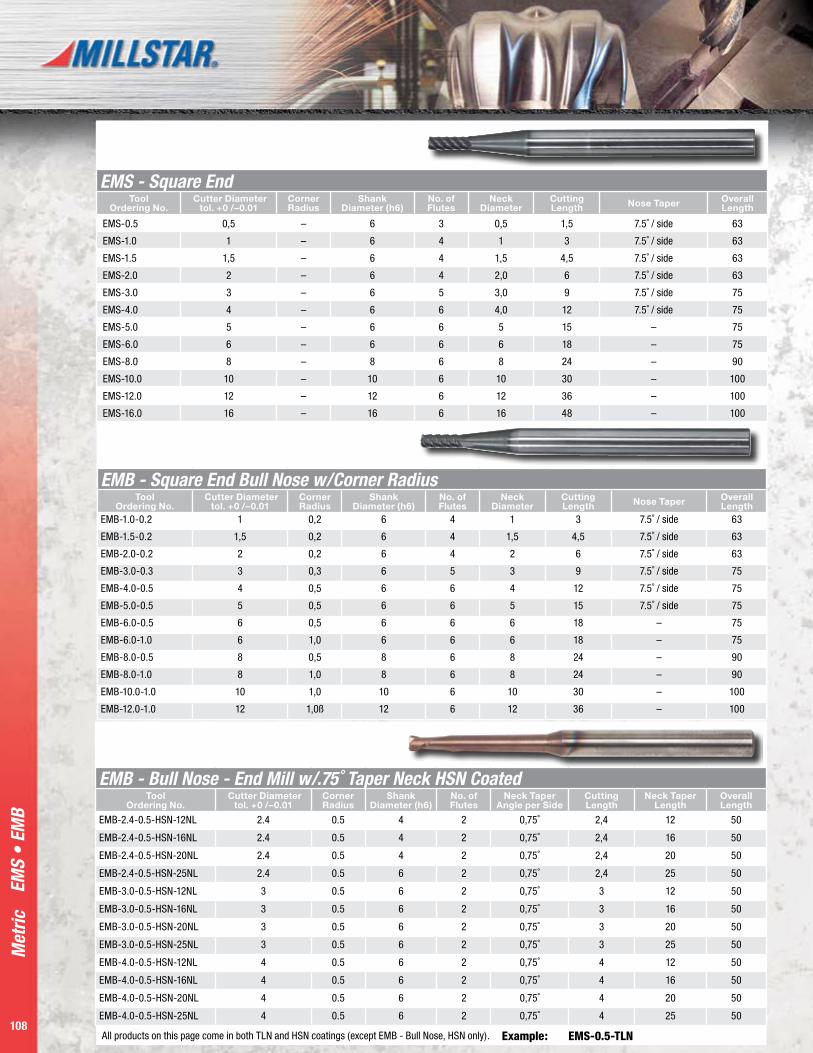
Met
ric
108
EMS
• EM
B
EMB - Square End Bull Nose w/Corner RadiusTool
Ordering No. Cutter Diameter
tol. +0 /–0.01Corner Radius
Shank Diameter (h6)
No. of Flutes
Neck Diameter
Cutting Length Nose Taper Overall
LengthEMB-1.0-0.2 1 0,2 6 4 1 3 7.5˚ / side 63
EMB-1.5-0.2 1,5 0,2 6 4 1,5 4,5 7.5˚ / side 63
EMB-2.0-0.2 2 0,2 6 4 2 6 7.5˚ / side 63
EMB-3.0-0.3 3 0,3 6 5 3 9 7.5˚ / side 75
EMB-4.0-0.5 4 0,5 6 6 4 12 7.5˚ / side 75
EMB-5.0-0.5 5 0,5 6 6 5 15 7.5˚ / side 75
EMB-6.0-0.5 6 0,5 6 6 6 18 – 75
EMB-6.0-1.0 6 1,0 6 6 6 18 – 75
EMB-8.0-0.5 8 0,5 8 6 8 24 – 90
EMB-8.0-1.0 8 1,0 8 6 8 24 – 90
EMB-10.0-1.0 10 1,0 10 6 10 30 – 100
EMB-12.0-1.0 12 1,0ß 12 6 12 36 – 100
EMS - Square EndTool
Ordering No. Cutter Diameter
tol. +0 /–0.01Corner Radius
Shank Diameter (h6)
No. of Flutes
Neck Diameter
Cutting Length Nose Taper Overall
Length
EMS-0.5 0,5 – 6 3 0,5 1,5 7.5˚ / side 63
EMS-1.0 1 – 6 4 1 3 7.5˚ / side 63
EMS-1.5 1,5 – 6 4 1,5 4,5 7.5˚ / side 63
EMS-2.0 2 – 6 4 2,0 6 7.5˚ / side 63
EMS-3.0 3 – 6 5 3,0 9 7.5˚ / side 75
EMS-4.0 4 – 6 6 4,0 12 7.5˚ / side 75
EMS-5.0 5 – 6 6 5 15 – 75
EMS-6.0 6 – 6 6 6 18 – 75
EMS-8.0 8 – 8 6 8 24 – 90
EMS-10.0 10 – 10 6 10 30 – 100
EMS-12.0 12 – 12 6 12 36 – 100
EMS-16.0 16 – 16 6 16 48 – 100
EMB - Bull Nose - End Mill w/.75˚ Taper Neck HSN CoatedTool
Ordering No. Cutter Diameter
tol. +0 /–0.01Corner Radius
Shank Diameter (h6)
No. of Flutes
Neck Taper Angle per Side
Cutting Length
Neck Taper Length
Overall Length
EMB-2.4-0.5-HSN-12NL 2.4 0.5 4 2 0,75˚ 2,4 12 50
EMB-2.4-0.5-HSN-16NL 2.4 0.5 4 2 0,75˚ 2,4 16 50
EMB-2.4-0.5-HSN-20NL 2.4 0.5 4 2 0,75˚ 2,4 20 50
EMB-2.4-0.5-HSN-25NL 2.4 0.5 6 2 0,75˚ 2,4 25 50
EMB-3.0-0.5-HSN-12NL 3 0.5 6 2 0,75˚ 3 12 50
EMB-3.0-0.5-HSN-16NL 3 0.5 6 2 0,75˚ 3 16 50
EMB-3.0-0.5-HSN-20NL 3 0.5 6 2 0,75˚ 3 20 50
EMB-3.0-0.5-HSN-25NL 3 0.5 6 2 0,75˚ 3 25 50
EMB-4.0-0.5-HSN-12NL 4 0.5 6 2 0,75˚ 4 12 50
EMB-4.0-0.5-HSN-16NL 4 0.5 6 2 0,75˚ 4 16 50
EMB-4.0-0.5-HSN-20NL 4 0.5 6 2 0,75˚ 4 20 50
EMB-4.0-0.5-HSN-25NL 4 0.5 6 2 0,75˚ 4 25 50
All products on this page come in both TLN and HSN coatings (except EMB - Bull Nose, HSN only). Example: EMS-0.5-TLN

P a g e 1 0 9
Met
ric
109
BM •
BM
4T •
BM
S
BM - Ball NoseTool
Ordering No. Cutter Diameter
tol. +0 /–0.01Ball
RadiusShank
Diameter (h6)No. of Flutes
Neck Diameter
Cutting Length Nose Taper Overall
Length
BM-0.5 0,5 0,25 6 2 – 0,5 7,5˚ / side 63
BM-0.6 0,6 0,30 6 2 - 0,6 7,5˚ / side 63
BM-0.8 0,8 0,40 6 2 - 0,8 7,5˚ / side 63
BM-1.0 1 0,50 6 2 – 1,0 7,5˚ / side 63
BM-1.5 1,5 0,75 6 2 – 1,5 7,5˚ / side 63
BM-2.0 2 1,00 6 2 – 2,0 7,5˚ / side 63
BM-3.0 3 1,50 6 2 – 3,0 7,5˚ / side 75
BM-4.0 4 2,00 6 2 – 4,0 7,5˚ / side 75
BM-5.0 5 2,50 6 2 – 5,0 7,5˚ / side 75
BM-6.0 6 3,00 6 2 – 6,0 – 75
BM-6.0-LL 6 3,00 6 2 - 6,0 - 100
BM-8.0 8 4,00 8 2 – 8,0 – 90
BM-8.0-LL 8 4,00 8 2 – 8,0 – 110
BM-10.0 10 5,00 10 2 – 10,0 – 100
BM-10.0-LL 10 5,00 10 2 - 10,0 - 120
BM-12.0 12 6,00 12 2 – 12,0 – 100
BM-12.0-LL 12 6,00 12 2 - 12,0 - 120
BM-16.0 16 8,00 16 2 – 16,0 – 100
BM-16.0-LL 16 8,00 16 2 – 16,0 – 150
BMS-LL – Z2 Angle 30˚ Tool Ordering
No. Cutter Diameter
tol. +0 /–0.01Corner Radius
Shank Diameter
No. of Flutes Cutting Length Overall Length
BMS-2.0-LL 2,0 1,0 6 2 4,0 75
BMS-3.0-LL 3,0 1,5 6 2 5,0 75
BMS-4.0-LL 4,0 2,0 6 2 6,0 75
BMS-5.0-LL 5,0 2,5 6 2 8,0 75
BMS-6.0-LL 6,0 3,0 6 2 10,0 75
BMS-8.0-LL 8,0 4,0 8 2 12,0 90
BMS-10.0-LL 10,0 5,0 10 2 16,0 120
BMS-12.0-LL 12,0 6,0 12 2 18,0 120
BM4T - Ballnose, Special Tip Design for HSM Tool
Ordering No. Cutter Diameter tol.
+0 /–0.0004Shank
Diameter Cutting Length Overall Length
BM4T-3.0 3 6 6 75
BM4T-4.0 4 6 8 75
BM4T-6.0 6 6 12 75
BM4T-8.0 8 8 16 90
BM4T-10.0 10 10 20 100
BM4T-12.0 12 12 24 100
All products on these pages come in both TLN and HSN coatings.
Examples: BM-0.5-TLN BMS-12.0-LL-HSN
Solid Carbide End Mill Program Tools
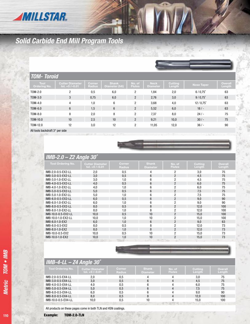
Met
ric
110
TOM
• IM
B
IMB-2.0 – Z2 Angle 30˚ Tool Ordering No. Cutter Diameter
tol. +0 /–0.01Corner Radius
Shank Diameter
No. of Flutes
Cutting Length
Overall Length
IMB-2.0-0.5-EX2-LL 2,0 0,5 4 2 3,0 75IMB-3.0-0.5-EX2-LL 3,0 0,5 6 2 4,5 75IMB-3.0-1.0-EX2-LL 3,0 1,0 6 2 4,5 75IMB-4.0-0.5-EX2-LL 4,0 0,5 6 2 6,0 75IMB-4.0-1.0-EX2-LL 4,0 1,0 6 2 6,0 75IMB-5.0-0.5-EX2-LL 5,0 0,5 6 2 7,5 75IMB-5.0-1.0-EX2-LL 5,0 1,0 6 2 7,5 75IMB-6.0-0.5-EX2-LL 6,0 0,5 6 2 9,0 90IMB-6.0-1.0-EX2-LL 6,0 1,0 6 2 9,0 90IMB-8.0-0.5-EX2-LL 8,0 0,5 8 2 12,0 100IMB-8.0-1.0-EX2-LL 8,0 1,0 8 2 12,0 100IMB-10.0-0.5-EX2-LL 10,0 0,5 10 2 15,0 100IMB-10.0-1.0-EX2-LL 10,0 1,0 10 2 15,0 100IMB-6.0-1.0-EX2 6,0 1,0 6 2 9,0 63IMB-8.0-0.5-EX2 8,0 0,5 8 2 12,0 73IMB-8.0-1.0-EX2 8,0 1,0 8 2 12,0 73IMB-10.0-0.5-EX2 10,0 0,5 10 2 15,0 73IMB-10.0-1.0-EX2 10,0 1,0 10 2 15,0 73
IMB-4-LL – Z4 Angle 30˚ Tool Ordering No. Cutter Diameter
tol. +0 /–0.01Corner Radius
Shank Diameter
No. of Flutes
Cutting Length
Overall Length
IMB-2.0-0.5-EX4-LL 2,0 0,5 4 4 3,0 75IMB-3.0-0.5-EX4-LL 3,0 0,5 6 4 4,5 75IMB-4.0-0.5-EX4-LL 4.0 0,5 6 4 6,0 75IMB-5.0-0.5-EX4-LL 5,0 0,5 6 4 7,5 75IMB-6.0-0.5-EX4-LL 6,0 0,5 6 4 9,0 90IMB-8.0-0.5-EX4-LL 8,0 0,5 8 4 12,0 100IMB-10.0-0.5-EX4-LL 10,0 0,5 10 4 15,0 100
TOM- ToroidTool
Ordering No. Cutter Diameter
tol. +0 /–0.01Corner Radius
Shank Diameter (h6)
No. of Flutes
Neck Diameter
Cutting Length Nose Taper Overall
Length
TOM-2.0 2 0,5 6,0 2 1,84 2,0 6 / 0,75˚ 63
TOM-3.0 3 0,75 6,0 2 2,76 3,0 9 / 0,75˚ 63
TOM-4.0 4 1,0 6 2 3,68 4,0 12 / 0,75˚ 63
TOM-6.0 6 1,5 6 2 5,52 6,0 18 / - 63
TOM-8.0 8 2,0 8 2 7,37 8,0 24 / - 75
TOM-10.0 10 2,5 10 2 9,21 10,0 30 / - 75
TOM-12.0 12 3,O 12 2 11,05 12,0 36 / - 90
All tools backdraft 3° per side
All products on these pages come in both TLN and HSN coatings.
Example: TOM-2.0-TLN
Solid Carbide End Mill Program Tools
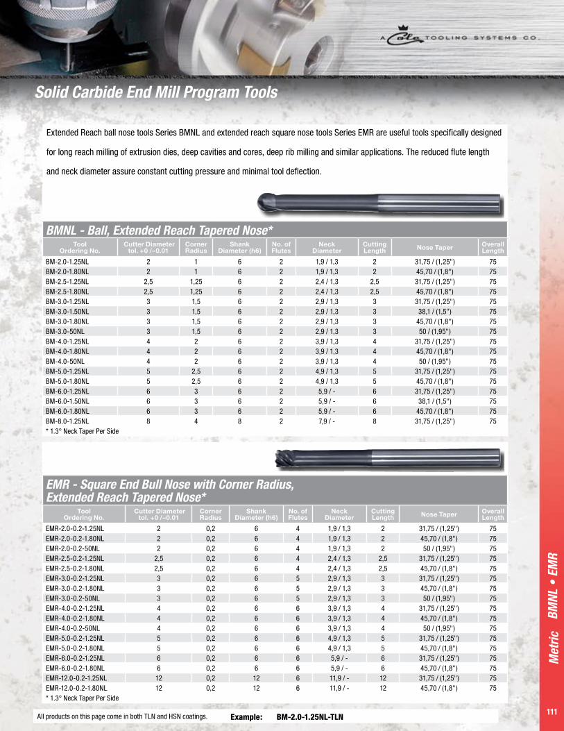
P a g e 111
Met
ric
111
BMNL - Ball, Extended Reach Tapered Nose* Tool
Ordering No. Cutter Diameter
tol. +0 /–0.01Corner Radius
Shank Diameter (h6)
No. of Flutes
Neck Diameter
Cutting Length Nose Taper Overall
Length
BM-2.0-1.25NL 2 1 6 2 1,9 / 1,3 2 31,75 / (1,25") 75BM-2.0-1.80NL 2 1 6 2 1,9 / 1,3 2 45,70 / (1,8") 75BM-2.5-1.25NL 2,5 1,25 6 2 2,4 / 1,3 2,5 31,75 / (1,25") 75BM-2.5-1.80NL 2,5 1,25 6 2 2,4 / 1,3 2,5 45,70 / (1,8") 75BM-3.0-1.25NL 3 1,5 6 2 2,9 / 1,3 3 31,75 / (1,25") 75BM-3.0-1.50NL 3 1,5 6 2 2,9 / 1,3 3 38,1 / (1,5") 75BM-3.0-1.80NL 3 1,5 6 2 2,9 / 1,3 3 45,70 / (1,8") 75BM-3.0-50NL 3 1,5 6 2 2,9 / 1,3 3 50 / (1,95") 75BM-4.0-1.25NL 4 2 6 2 3,9 / 1,3 4 31,75 / (1,25") 75BM-4.0-1.80NL 4 2 6 2 3,9 / 1,3 4 45,70 / (1,8") 75BM-4.0-50NL 4 2 6 2 3,9 / 1,3 4 50 / (1,95") 75BM-5.0-1.25NL 5 2,5 6 2 4,9 / 1,3 5 31,75 / (1,25") 75BM-5.0-1.80NL 5 2,5 6 2 4,9 / 1,3 5 45,70 / (1,8") 75BM-6.0-1.25NL 6 3 6 2 5,9 / - 6 31,75 / (1,25") 75BM-6.0-1.50NL 6 3 6 2 5,9 / - 6 38,1 / (1,5") 75BM-6.0-1.80NL 6 3 6 2 5,9 / - 6 45,70 / (1,8") 75BM-8.0-1.25NL 8 4 8 2 7,9 / - 8 31,75 / (1,25") 75* 1.3° Neck Taper Per Side
EMR - Square End Bull Nose with Corner Radius, Extended Reach Tapered Nose*
Tool Ordering No.
Cutter Diameter tol. +0 /–0.01
Corner Radius
Shank Diameter (h6)
No. of Flutes
Neck Diameter
Cutting Length Nose Taper Overall
Length
EMR-2.0-0.2-1.25NL 2 0,2 6 4 1,9 / 1,3 2 31,75 / (1,25") 75EMR-2.0-0.2-1.80NL 2 0,2 6 4 1,9 / 1,3 2 45,70 / (1,8") 75EMR-2.0-0.2-50NL 2 0,2 6 4 1,9 / 1,3 2 50 / (1,95") 75EMR-2.5-0.2-1.25NL 2,5 0,2 6 4 2,4 / 1,3 2,5 31,75 / (1,25") 75EMR-2.5-0.2-1.80NL 2,5 0,2 6 4 2,4 / 1,3 2,5 45,70 / (1,8") 75EMR-3.0-0.2-1.25NL 3 0,2 6 5 2,9 / 1,3 3 31,75 / (1,25") 75EMR-3.0-0.2-1.80NL 3 0,2 6 5 2,9 / 1,3 3 45,70 / (1,8") 75EMR-3.0-0.2-50NL 3 0,2 6 5 2,9 / 1,3 3 50 / (1,95") 75EMR-4.0-0.2-1.25NL 4 0,2 6 6 3,9 / 1,3 4 31,75 / (1,25") 75EMR-4.0-0.2-1.80NL 4 0,2 6 6 3,9 / 1,3 4 45,70 / (1,8") 75EMR-4.0-0.2-50NL 4 0,2 6 6 3,9 / 1,3 4 50 / (1,95") 75EMR-5.0-0.2-1.25NL 5 0,2 6 6 4,9 / 1,3 5 31,75 / (1,25") 75EMR-5.0-0.2-1.80NL 5 0,2 6 6 4,9 / 1,3 5 45,70 / (1,8") 75EMR-6.0-0.2-1.25NL 6 0,2 6 6 5,9 / - 6 31,75 / (1,25") 75EMR-6.0-0.2-1.80NL 6 0,2 6 6 5,9 / - 6 45,70 / (1,8") 75EMR-12.0-0.2-1.25NL 12 0,2 12 6 11,9 / - 12 31,75 / (1,25") 75EMR-12.0-0.2-1.80NL 12 0,2 12 6 11,9 / - 12 45,70 / (1,8") 75* 1.3° Neck Taper Per Side
Extended Reach ball nose tools Series BMNL and extended reach square nose tools Series EMR are useful tools specifically designed
for long reach milling of extrusion dies, deep cavities and cores, deep rib milling and similar applications. The reduced flute length
and neck diameter assure constant cutting pressure and minimal tool deflection.
BMNL
• E
MR
All products on this page come in both TLN and HSN coatings. Example: BM-2.0-1.25NL-TLN
Solid Carbide End Mill Program Tools

Met
ric
112
EMS2
• E
MS4
• A
lum
ista
r EM
SA •
Alu
mis
tar B
MA
• B
M2
• BM
4
EMS2...LL - 2 Flute Long Series Endmill, Sq. EndTool
Ordering No.
Cutter Diameter
tol. +0 /–0.015
Corner Radius
(R1)
Shank Diameter
(D1)
Cutting Length
(L1)
Total Length
(L2)
EMS2-03-LL- 3 XX 3 16 50
EMS2-04-LL- 4 XX 4 20 76
EMS2-06-LL- 6 XX 6 25 76
EMS2-08-LL- 8 XX 8 25 76
EMS2-10-LL- 10 XX 10 25 101
EMS2-12-LL- 12 XX 12 25 101
EMS2-16-LL- 16 XX 16 50 152
EMS2-20-LL- 20 XX 20 50 152
EMS4...LL - 4 Flute Long Series Endmill, Sq. EndTool
Ordering No.
Cutter Diameter
tol. +0 /–0.015
Corner Radius
(R1)
Shank Diameter
(D1)
Cutting Length
(L1)
Total Length
(L2)
EMS4-03-LL- 3 XX 3 16 50
EMS4-04-LL- 4 XX 4 20 76
EMS4-06-LL- 6 XX 6 25 76
EMS4-08-LL- 8 XX 8 25 76
EMS4-10-LL- 10 XX 10 25 101
EMS4-12-LL- 12 XX 12 25 101
EMS4-16-LL- 16 XX 16 50 152
EMS4-20-LL- 20 XX 20 50 152
AlumiSTAR EMSA - 3 Flute Endmill, 45° - Aluminum
Tool Ordering
No.
Cutter Diameter
tol. +0 /–0.015
Corner Radius
(R1)
Shank Diameter
(D1)
Cutting Length
(L1)
Total Length
(L2)
EMSA-04- 4 XX 4,000 14 50
EMSA-06- 6 XX 6,000 19 63
EMSA-08- 8 XX 8,000 22 63
EMSA-10- 10 XX 10,000 25 63
EMSA-12- 12 XX 12,000 25 76
EMSA-16- 16 XX 16,000 38 92
EMSA-20- 20 XX 20,000 38 101
AlumiSTAR BMA - 3 Flute Endmill, Ballnose 45° - Aluminum
Tool Ordering
No.
Cutter Diameter
tol. +0 /–0.015
Corner Radius
(R1)
Shank Diameter
(D1)
Cutting Length
(L1)
Total Length
(L2)
BMA-03- 3 1,5 3,000 12 38
BMA-04- 4 2 4,000 14 50
BMA-06- 6 3 6,000 19 63
BMA-08- 8 4 8,000 22 63
BMA-10- 10 5 10,000 25 63
BMA-12- 12 6 12,000 25 76
BMA-16- 16 8 16,000 38 92
BMA-20- 20 10 20,000 38 101
BM2 - 2 Flute Long Series Endmill, Ballnose Tool
Ordering No.
Cutter Diameter
tol. +0 /–0.015
Corner Radius
(R1)
Shank Diameter
(D1)
Cutting Length
(L1)
Total Length
(L2)
BM2-03-LL- 3 1,5 3 16 50
BM2-04-LL- 4 2 4 20 76
BM2-06-LL- 6 3 6 25 76
BM2-08-LL- 8 4 8 25 76
BM2-10-LL- 10 5 10 25 101
BM2-12-LL- 12 6 12 25 101
BM2-16-LL- 16 8 16 50 152
BM2-20-LL- 20 10 20 50 152
BM4 - 4 Flute Endmill Long Series, BallnoseTool
Ordering No.
Cutter Diameter
tol. +0 /–0.015
Corner Radius
(R1)
Shank Diameter
(D1)
Cutting Length
(L1)
Total Length
(L2)
BM4-03-LL- 3 1,5 3 16 50
BM4-04-LL- 4 2 4 20 76
BM4-06-LL- 6 3 6 25 76
BM4-08-LL- 8 4 8 25 76
BM4-10-LL- 10 5 10 25 101
BM4-12-LL- 12 6 12 25 101
BM4-16-LL- 16 8 16 50 152
BM4-20-LL- 20 10 20 50 152
Ultra Precision End Mills

P a g e 11 3
Met
ric
113
EMV4
• B
M22
0 •
BM •
EM
S2 •
EM
S4
EMV4 - 4 Flute Variable Fluted Endmill, Square End w/45° Chamfer
Tool Ordering
No.
Cutter Diameter
tol. +0 /–0.015
Corner Radius
(R1)
Shank Diameter
(D1)
Cutting Length
(L1)
Total Length
(L2)
EMV4-03- 3 XX 3 16 38
EMV4-04- 4 XX 4 20 50
EMV4-06- 6 XX 6 25 63
EMV4-08- 8 XX 8 25 63
EMV4-10- 10 XX 10 25 63
EMV4-12- 12 XX 12 25 76
EMV4-16- 16 XX 16 50 92
EMV4-20- 20 XX 20 50 101
BM220 - 220° 2 Flute Endmill, BallnoseTool
Ordering No.
Cutter Diameter
tol. +0 /–0.015
Corner Radius
(R1)
Shank Diameter
(D1)
Cutting Length
(L1)
Total Length
(L2)
BM220-03- 3 1,5 3 2,25 38
BM220-04- 4 2 4 3,00 50
BM220-06- 6 3 6 4,50 63
BM220-08- 8 4 8 6,00 63
BM220-10- 10 5 10 7,50 63
BM220-12- 12 6 12 9,00 76
EMS2 - 2 Flute Endmill, Square End Tool
Ordering No.
Cutter Diameter
tol. +0 /–0.015
Corner Radius
(R1)
Shank Diameter
(D1)
Cutting Length
(L1)
Total Length
(L2)
EMS2-01- 1* XX 3,000 4 38
EMS2-02- 2* XX 3,000 8 38
EMS2-03- 3 XX 3,000 12 38
EMS2-04- 4 XX 4,000 14 50
EMS2-06- 6 XX 6,000 19 63
EMS2-08- 8 XX 8,000 22 63
EMS2-10- 10 XX 10,000 25 63
EMS2-12- 12 XX 12,000 25 76
EMS2-16- 16 XX 16,000 38 92
EMS2-20- 20 XX 20,000 38 101
EMS4 - 4 Flute Endmill, Square End Tool
Ordering No.
Cutter Diameter
tol. +0 /–0.015
Corner Radius
(R1)
Shank Diameter
(D1)
Cutting Length
(L1)
Total Length
(L2)
EMS4-03- 3 XX 3,000 12 38
EMS4-04- 4 XX 4,000 14 50
EMS4-06- 6 XX 6,000 19 63
EMS4-08- 8 XX 8,000 22 63
EMS4-10- 10 XX 10,000 25 63
EMS4-12- 12 XX 12,000 25 76
EMS4-16- 16 XX 16,000 38 92
EMS4-20- 20 XX 20,000 38 101
BM - Ball Nose w/.75˚ Taper Neck HSN CoatedTool
Ordering No. Cutter Diameter
tol. +0 /–0.01Corner Radius
Shank Diameter (h6)
No. of Flutes
Neck Taper Angle per Side
Cutting Length
Neck Taper Length
Overall Length
BM-2.0-HSN-16NL 2 1 6 2 0,75˚ 2 16 50
BM-2.0-HSN-21NL 2 1 6 2 0,75˚ 2 21 50
BM-2.0-HSN-26NL 2 1 6 2 0,75˚ 2 26 50
BM-2.0-HSN-31.75NL 2 1 6 2 0,75˚ 2 31,75 50
BM-2.4-HSN-16NL 2,4 1,2 6 2 0,75˚ 2,4 16 50
BM-2.4-HSN-21NL 2,4 1,2 6 2 0,75˚ 2,4 21 50
BM-2.4-HSN-26NL 2,4 1,2 6 2 0,75˚ 2,4 26 50
BM-2.4-HSN-31.75NL 2,4 1,2 6 2 0,75˚ 2,4 31,75 50
Ultra Precision End Mills
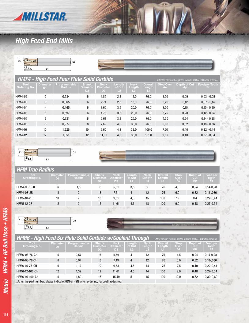
Met
ric
114
HMF4 - High Feed Four Flute Solid Carbide ...After the part number, please indicate XRN or HSN when ordering.
Tool Ordering No.
Diameter D1
Programmable Radius
Shank Diameter
D2
Neck Diameter
D3
Length of Cut
L2
Neck Length
L3
Overall Length
L1
Step Over Ae
Depth of Cut Ap
Feed per Tooth Fz
HFM4-02 2 0,234 6 1,85 2,2 12,0 76,0 1,50 0,09 0,03 - 0,05
HFM4-03 3 0,365 6 2,74 2,8 16,0 76,0 2,25 0,12 0,07 - 0,14
HFM4-04 4 0,465 6 3,60 3,5 20,0 76,0 3,00 0,15 0,10 - 0,20
HFM4-05 5 0,597 6 4,75 3,5 20,0 76,0 3,75 0,20 0,12 - 0,24
HFM4-06 6 0,731 6 5,61 3,8 25,0 76,0 4,50 0,24 0,14 - 0,28
HFM4-08 8 0,977 8 7,62 4,0 30,0 76,0 6,00 0,32 0,18 - 0,36
HFM4-10 10 1,226 10 9,60 4,3 33,0 100,0 7,50 0,40 0,22 - 0,44
HFM4-12 12 1,651 12 11,61 4,6 38,0 101,0 9,09 0,48 0,27 - 0,54
HFM
4 •
HF B
ull N
ose
• HF
M6
High Feed End Mills
HFM6 - High Feed Six Flute Solid Carbide w/Coolant Through ...After the part number, please indicate XRN or HSN when ordering.
Tool Ordering No.
Diameter D1
Programmable Radius
Shank Diameter
D2
Neck Diameter
D3
Length of Cut
L2
Neck Length
L3
Overall Length
L1
Step Over Ae
Depth of Cut Ap
Feed per Tooth
Fz
HFM6-06-76-CH 6 0,57 6 5,59 4 12 76 4,5 0,24 0,14-0,28
HFM6-08-76-CH 8 0,94 8 7,49 4 12 76 6,0 0,32 0,18-,036
HFM6-10-76-CH 10 1,10 10 9,53 4.5 14 76 7,5 0,40 0,22-0,44
HFM6-12-100-CH 12 1,32 12 11,61 4.5 14 100 9,0 0,48 0,27-0,54
HFM6-16-100-CH 16 1,80 16 15,49 5 15 100 12,0 0,52 0,30-0,60...After the part number, please indicate XRN or HSN when ordering, for coating desired.
HFM True RadiusTool
Ordering No.Diameter
D1Programmable
RadiusShank
DiameterD2
Neck Diameter
D3
Length of Cut
L2
Neck Length
L3
Overall Length
L1
Step Over Ae
Depth of Cut Ap
Feed per Tooth
Fz
HFM4-06-1.5R 6 1,5 6 5,61 3,5 9 76 4,5 0,24 0,14-0,28
HFM4-08-2R 8 2 8 7,61 4 12 76 6,0 0,32 0,18-,036
HFM5-10-2R 10 2 10 9,61 4,3 15 100 7,5 0,4 0,22-0,44
HFM5-12-2R 12 2 12 11,61 4,6 18 100 9,0 0,48 0,27-0,54

P a g e 11 5
Met
ric
115
HFM Cutting ConditionsWork Material
USA/W.-Nr./JISMaterial
Hardness HrcCutting Depth at Diameter ap max Cutting Width
Ae maxCoating type
recommended2 3 4 5 6 8 10 12
H13/1.2344/SKD61 <41 0,09 0,12 0,15 0,2 0,24 0,32 0,4 0,48 75% XRN/HSN
H13/1.2344/SKD61 41-50 0,09 0,12 0,15 0,2 0,24 0,32 0,4 0,48 75% XRN/HSN
H13/1.2344/SKD61 51+ 0,08 0,1 0,12 0,18 0,2 0,3 0,3 0,4 75% HSN
A2/1,2363/SKD12 <41 0,09 0,12 0,15 0,2 0,24 0,32 0,4 0,48 75% XRN/HSN
A2/1,2363/SKD12 41-50 0,09 0,12 0,15 0,2 0,24 0,32 0,4 0,48 75% XRN/HSN
A2/1,2363/SKD12 51+ 0,08 0,1 0,12 0,18 0,2 0,3 0,3 0,4 75% HSN
P20/1,2330 <41 0,09 0,12 0,15 0,2 0,24 0,32 0,4 0,48 75% XRN/HSN
P20/1,2330 41-50 0,09 0,12 0,15 0,2 0,24 0,32 0,4 0,48 75% XRN/HSN
D2/1,2379/SKD11 <41 0,09 0,12 0,15 0,2 0,24 0,32 0,4 0,48 75% XRN/HSN
D2/1,2379/SKD11 41-50 0,09 0,12 0,15 0,2 0,24 0,32 0,4 0,48 75% XRN/HSN
D2/1,2379/SKD11 51+ 0,08 0,1 0,12 0,2 0,24 0,32 0,3 0,4 75% HSN
Grey Cast Iron/GG <41 0,09 0,12 0,15 0,2 0,24 0,32 0,4 0,48 75% XRN/HSN
Cast Iron/GGG 41+ 0,09 0,12 0,15 0,2 0,24 0,32 0,4 0,48 75% XRN/HSN
Titanium (6AL 4V) 0,09 0,12 0,15 0,2 0,24 0,32 0,4 0,48 75% XRN/HSN
Work MaterialUSA/W,-Nr,/JIS
Cut speed at Dm/minute
Max feed per tooth fz at cutting insert dia D2 3 4 5 6 8 10 12
H13/1,2344/SKD61 244-365 0,03-0,05 0,07-0,14 0,10-0,2 0,12-0,24 0,14-0,28 0,18-0,36 0,22-0,44 0,27-0,54
H13/1.2344/SKD61 183-244 0,03-0,05 0,07-0,14 0,10-0,2 0,12-0,24 0,14-0,28 0,18-0,36 0,22-0,44 0,27-0,54
H13/1.2344/SKD61 90-150 0,03-0,05 0,07-0,14 0,10-0,2 0,12-0,24 0,14-0,28 0,18-0,36 0,22-0,44 0,27-0,54
A2/1,2363/SKD12 244-365 0,03-0,05 0,07-0,14 0,10-0,2 0,12-0,24 0,14-0,28 0,18-0,36 0,22-0,44 0,27-0,54
A2/1,2363/SKD12 183-244 0,03-0,05 0,07-0,14 0,10-0,2 0,12-0,24 0,14-0,28 0,18-0,36 0,22-0,44 0,27-0,54
A2/1,2363/SKD12 90-150 0,03-0,05 0,07-0,14 0,10-0,2 0,12-0,24 0,14-0,28 0,18-0,36 0,22-0,44 0,27-0,54
P20/1,2330 244-365 0,03-0,05 0,07-0,14 0,10-0,2 0,12-0,24 0,14-0,28 0,18-0,36 0,22-0,44 0,27-0,54
P20/1,2330 183-244 0,03-0,05 0,07-0,14 0,10-0,2 0,12-0,24 0,14-0,28 0,18-0,36 0,22-0,44 0,27-0,54
D2/1,2379/SKD11 183-244 0,03-0,05 0,07-0,14 0,10-0,2 0,12-0,24 0,14-0,28 0,18-0,36 0,22-0,44 0,27-0,54
D2/1,2379/SKD11 105-140 0,03-0,05 0,07-0,14 0,10-0,2 0,12-0,24 0,14-0,28 0,18-0,36 0,22-0,44 0,27-0,54
D2/1,2379/SKD11 80-140 0,03-0,05 0,07-0,14 0,10-0,2 0,12-0,24 0,14-0,28 0,18-0,36 0,22-0,44 0,27-0,54
Grey Cast Iron/GG 350-900 0,03-0,05 0,07-0,14 0,10-0,2 0,12-0,24 0,14-0,28 0,18-0,36 0,22-0,44 0,27-0,54
Cast Iron/GGG 250-400 0,03-0,05 0,07-0,14 0,10-0,2 0,12-0,24 0,14-0,28 0,18-0,36 0,22-0,44 0,27-0,54
Titanium (6AL 4V) 120-180 0,03-0,05 0,07-0,14 0,10-0,2 0,12-0,24 0,14-0,28 0,18-0,36 0,22-0,44 0,27-0,54
Cutt
ing
Cond
ition
s
High Feed End Mills

Met
ric
116
High Performance Aerospace Aluminum End Mills
ALP2
AlumiSTAR ALP - 2 Flute Endmill - Aluminum
Tool Ordering Number
Cutter Diameter
(D1)
Cutting Length
(L2)Neck Length
(L3)
Neck Diameter
(D3) Radius FlutesTotal Length
(L1)Diameter
(D2)
ALP2-8-2.3-75-NA 8 10 40 7,5 2,3 2 75 8
ALP2-8-3.2-75-NA 8 10 40 7,5 3,2 2 75 8
ALP2-10-0.3-100-NA 10 12 50 9,4 0,3 2 100 10
ALP2-10-3.2-72-NA 10 10 40 9,5 3,2 2 72 10
ALP2-12-0.0-110-NA 12 15 75 11,5 0 2 110 12
ALP2-12-110-NA 12 20 70 11,5 0 2 110 12
ALP2-12-2.5-75-NA 12 15 45 11,5 2,5 2 75 12
ALP2-12-3.0-115-NA 12 20 75 11,5 3 2 115 12
ALP2-12-3.0-120-NA 12 15 50 11,5 3 2 120 12
ALP2-12-3.2-83-NA 12 15 50 11,5 3,2 2 83 12
ALP2-12-3.6-73-NA 12 15 40 11,5 3,6 2 73 12
ALP2-12-4.8-73-NA 12 15 40 11,5 4,8 2 73 12
ALP2-12-5.0-83-NA 12 15 50 11,5 5 2 83 12
ALP2-12-5.1-73-NA 12 15 40 11,5 5,1 2 73 12
ALP2-14-0.0-85-NA 14 20 55 13,5 0 2 85 14
ALP2-14-0.0-150-NA 14 20 115 13,5 0 2 150 14
ALP2-14-3.2-120-NA 14 15 95 13,5 3,2 2 120 14
ALP2-14-6.3-75-NA 14 15 45 13,5 6,3 2 75 14
ALP2-16-0.0-92-NA 16 32 none none 0 2 92 16
ALP2-16-0.0-110-NA 16 20 85 15 0 2 110 16
ALP2-16-2.5-92-NA 16 32 none none 2,5 2 92 16
ALP2-16-3.0-92-NA 16 32 none none 3 2 92 16
ALP2-16-3.0-110-NA 16 20 85 15 3 2 110 16
ALP2-16-3.0-160-NA 16 20 130 15 3 2 160 16
ALP2-16-3.2-82-NA 16 20 50 15 3,2 2 82 16
ALP2-16-3.2-130-NA 16 20 95 15 3,2 2 130 16
ALP2-16-3.6-92-NA 16 20 55 15 3,6 2 92 16
ALP2-16-4.0-92-NA 16 32 none none 4 2 92 16
ALP2-16-5.0-82-NA 16 20 50 15 5 2 82 16
ALP2-16-6.3-82-NA 16 20 50 15 6,3 2 82 16
ALP2-20-0.0-104-NA 20 38 none none 0 2 104 20
ALP2-20-0.0-150-NA 20 20 100 19 0 2 150 20
ALP2-20-1.5-120-NA 20 20 90 19 1,5 2 120 20
ALP2-20-2.5-104-NA 20 38 none none 2,5 2 104 20
ALP2-20-3.0-120-NA 20 20 85 19 3 2 120 20
ALP2-20-3.0-150-NA 20 20 110 19 3 2 150 20
ALP2-20-3.0-165-NA 20 20 130 19 3 2 165 20
ALP2-20-3.2-92-NA 20 20 60 19 3,2 2 92 20
ALP2-20-3.2-130-NA 20 20 95 19 3,2 2 130 20
ALP2-20-3.2-150-NA 20 20 115 19 3,2 2 150 20
ALP2-20-6.3-92-NA 20 20 60 19 6,3 2 92 20
ALP2-20-6.3-130-NA 20 20 100 19 6,3 2 130 20
ALP2-20-5.0-150-NA 20 20 110 19 5 2 150 20
ALP2-20-5.0-165-NA 20 20 140 19 5 2 165 20
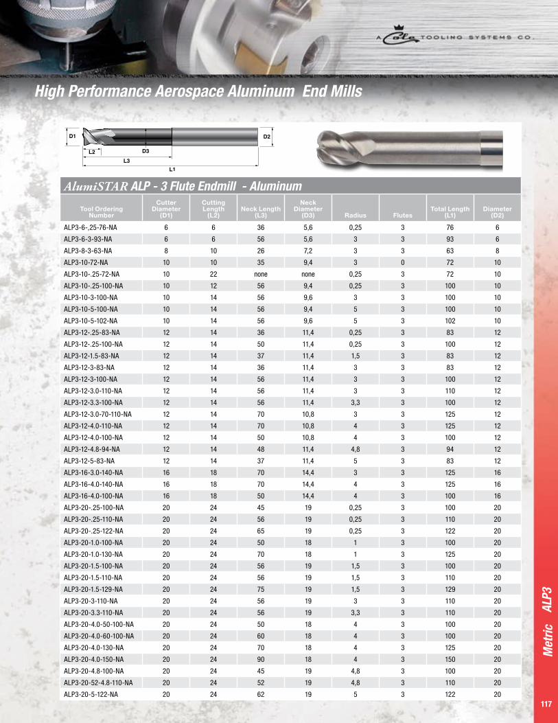
P a g e 11 7
Met
ric
117
ALP3
AlumiSTAR ALP - 3 Flute Endmill - Aluminum
Tool Ordering Number
Cutter Diameter
(D1)
Cutting Length
(L2)Neck Length
(L3)
Neck Diameter
(D3) Radius FlutesTotal Length
(L1)Diameter
(D2)
ALP3-6-,25-76-NA 6 6 36 5,6 0,25 3 76 6
ALP3-6-3-93-NA 6 6 56 5,6 3 3 93 6
ALP3-8-3-63-NA 8 10 26 7,2 3 3 63 8
ALP3-10-72-NA 10 10 35 9,4 3 0 72 10
ALP3-10-.25-72-NA 10 22 none none 0,25 3 72 10
ALP3-10-.25-100-NA 10 12 56 9,4 0,25 3 100 10
ALP3-10-3-100-NA 10 14 56 9,6 3 3 100 10
ALP3-10-5-100-NA 10 14 56 9,4 5 3 100 10
ALP3-10-5-102-NA 10 14 56 9,6 5 3 102 10
ALP3-12-.25-83-NA 12 14 36 11,4 0,25 3 83 12
ALP3-12-.25-100-NA 12 14 50 11,4 0,25 3 100 12
ALP3-12-1.5-83-NA 12 14 37 11,4 1,5 3 83 12
ALP3-12-3-83-NA 12 14 36 11,4 3 3 83 12
ALP3-12-3-100-NA 12 14 56 11,4 3 3 100 12
ALP3-12-3.0-110-NA 12 14 56 11,4 3 3 110 12
ALP3-12-3.3-100-NA 12 14 56 11,4 3,3 3 100 12
ALP3-12-3.0-70-110-NA 12 14 70 10,8 3 3 125 12
ALP3-12-4.0-110-NA 12 14 70 10,8 4 3 125 12
ALP3-12-4.0-100-NA 12 14 50 10,8 4 3 100 12
ALP3-12-4.8-94-NA 12 14 48 11,4 4,8 3 94 12
ALP3-12-5-83-NA 12 14 37 11,4 5 3 83 12
ALP3-16-3.0-140-NA 16 18 70 14,4 3 3 125 16
ALP3-16-4.0-140-NA 16 18 70 14,4 4 3 125 16
ALP3-16-4.0-100-NA 16 18 50 14,4 4 3 100 16
ALP3-20-.25-100-NA 20 24 45 19 0,25 3 100 20
ALP3-20-.25-110-NA 20 24 56 19 0,25 3 110 20
ALP3-20-.25-122-NA 20 24 65 19 0,25 3 122 20
ALP3-20-1.0-100-NA 20 24 50 18 1 3 100 20
ALP3-20-1.0-130-NA 20 24 70 18 1 3 125 20
ALP3-20-1.5-100-NA 20 24 56 19 1,5 3 100 20
ALP3-20-1.5-110-NA 20 24 56 19 1,5 3 110 20
ALP3-20-1.5-129-NA 20 24 75 19 1,5 3 129 20
ALP3-20-3-110-NA 20 24 56 19 3 3 110 20
ALP3-20-3.3-110-NA 20 24 56 19 3,3 3 110 20
ALP3-20-4.0-50-100-NA 20 24 50 18 4 3 100 20
ALP3-20-4.0-60-100-NA 20 24 60 18 4 3 100 20
ALP3-20-4.0-130-NA 20 24 70 18 4 3 125 20
ALP3-20-4.0-150-NA 20 24 90 18 4 3 150 20
ALP3-20-4.8-100-NA 20 24 45 19 4,8 3 100 20
ALP3-20-52-4.8-110-NA 20 24 52 19 4,8 3 110 20
ALP3-20-5-122-NA 20 24 62 19 5 3 122 20
High Performance Aerospace Aluminum End Mills

P a g e 11 8
Inch
118
SD Collet & HM Milling Chuck Contents
BT....SD
CT...SD
HSK...SD
SD Collet High Accuracy Chucks 120-121
HM...BT
HM...CAT
HM...HSK
HM Milling Chucks 120-121
SD Collet ChuckMeasurement System
Interface Collet Type
Gage Length
Imperial CT40 SD-16 80mmMetric BT40 SD-16 90mm
118
Sect
ion
Cont
ents
HM Milling ChuckMeasurement System
Denoted MillingChuck Size
Collet OD
Gage Length Interface
Imperial HM 32mm 4 CAT40Metric HM 32mm 105 BT40

P a g e 11 9
Met
ric
119
SD Collet Chucks
CAT, BT and HSK styles:
• SD design increases gripping power/torque
over the traditional ER collet system with
4˚ per side angle contact.
• Maximum runout (0.007mm @ 4XD) increases
accuracy and tool life while minimizing rework.
Consistent repeatability shortens set-up time
and improves productivity.
• Off the shelf balance specifications of G6.3 at 20,000
rpm provides confidence in high speed machining
applications and high accuracy requirements.
• Durable, case hardened chucks.
119
SD C
olle
t & H
M M
illin
g Ch
ucks
HM Milling Chucks
CAT, BT and HSK styles:
• More efficient & effective roughing operations.
• Exceptional rigidity under side loads.
• Strong chucking torque eliminates cutting tool slip
and maximizes griping power.
• Decreased vibration extends tool life and improves
surface finishes for secondary operations.
• Superior concentric positioning improves accuracy.
and allows closer to net shape machining.
• Very competitively priced.

Met
ric
120
BT S
D •
CT
SD •
HSK
SD
• SD
Col
lets
• S
D Cl
ampi
ng N
ut S
D Sp
anne
r Wre
nch
D d
L
SD Collet Chucks (high accuracy) Tool Ordering No. Length L Diameter D Clamping Range d Weight Kg
BT40-SD16-90 90mm 41mm 2,75-16mm 1,3
BT50-SD16-100 100mm 41mm 2,75-16mm 3,2
D d
L
CT40-SD16-80 80mm 41mm 2,75-16mm 1,3
CT50-SD16-100 100mm 41mm 2,75-16mm 3,2
D d
L
HSK63A-SD16-80 80mm 41mm 2,75-16mm 1,1
HSK100A-SD16-100 100mm 41mm 2,75-16mm 2,5
d
SD Collets Tool Ordering No. Range d Tool Ordering No. Range d Tool Ordering No. Range d Tool Ordering No. Range d
SD-16-3 2,5-3,0 SD-16-6,5 6,0-6,5 SD-16-10 9,5-10,0 SD-16-13.5 13,0-13,5SD-16-3.5 3,0-3,5 SD-16-7 6,5-7,0 SD-16-10.5 10,0-10,5 SD-16-14 13,5-14,0SD-16-4 3,5-4,0 SD-16-7.5 7,0-7,5 SD-16-11 10,5-11,0 SD-16-14.5 14,0-14,5SD-16-4.5 4,0-4,5 SD-16-8 7,5-8,0 SD-16-11.5 11,0-11,5 SD-16-15 14,5-15,0SD-16-5 4,5-5,0 SD-16-8.5 8,0-8,5 SD-16-12 11,5-12,0 SD-16-15.5 15,0-15,5SD-16-5.5 5,0-5,5 SD-16-9 8,5-9,0 SD-16-12.5 12,0-12,5 SD-16-16 15,5-16,0SD-16-6 5,5-6,0 SD-16-9,5 9,0-9,5 SD-16-13 12,5-13,0
SD Clamping NutTool Ordering No. Length L Diameter D
SD-16-Nut 24 41
SD Spanner WrenchTool Ordering No. Length L Diameter D
SD-S-16 170 41
SD Collet Chucks

P a g e 1 2 1
Met
ric
121
HM B
T •
HM H
SK •
HM
C Co
llets
• H
M-S
Spa
nner
Wre
nch
D
d
L
HM Milling Chucks Tool Ordering No. Length L Diameter D Diameter d Clamping Range d Weight Kg
HM32-105-BT40 105mm 73,5mm 32mm 6-32mm* 2,4
HM32-105-BT50 105mm 73,5mm 32mm 6-32mm* 5
D
d
L
HM32-100-HSK63A 100mm 73,5mm 32mm 6-32mm* 2,1
HM32-100-HSK100A 100mm 73,5mm 32mm 6-32mm* 3,4
D d
HMC Collets Tool Ordering No. Diameter D Diameter d
HMC-32-6 32mm 6HMC-32-8 32mm 8HMC-32-10 32mm 10HMC-32-12 32mm 12HMC-32-14 32mm 14HMC-32-16 32mm 16HMC-32-18 32mm 18HMC-32-20 32mm 20HMC-32-25 32mm 25
HM-S Spanner WrenchTool Ordering No. Length L Diameter D
HM-S-40 265 70
HM Milling Chucks

4930 S. Lapeer Road • Orion Twp., MI 48359 • 1.877.MILLSTAR • www.millstar.com
LIMITED WARRANTY
Millstar Warrants to all distributors and industrial users that the products supplied by Millstar shall be free from defects in material and workmanship.
For a period of thirty days from the date of sale, Millstar will repair or replace (at no additional cost to the customer) any standard Millstar product which Millstar
determines contains defects in material or workmanship. Alternately, at its sole discretion, Millstar may credit all or part of the purchase price for such product. However, complete operating conditions and any other information requested by Millstar must accompany
claims made under this Warranty. Millstar cannot issue credit or accept returns on special items.
EXCLUSION OF OTHER WARRANTIES AND POLICIES
There are no warranties, express or implied, which extend beyond the warranty description on the face hereof and specifically, MILLSTAR AND ITS AFFILIATED
COMPANIES EXCLUDE ANY IMPLIED WARRANTY OF MERCHANTABILITY OR FITNESS FOR A PARTICULAR USE. Millstar and its affiliated companies shall have no liability or responsibility for any claim or loss arising out of design, manufacture, sale or use of its products other than to repair or replace its products as described above. IN NO EVENT
SHALL MILLSTAR OR ITS AFFILIATED COMPANIES BE LIABLE FOR ANY SPECIAL, CONSEQUENTIAL OR INCIDENTAL DAMAGES.
Any misuse or alteration of the product will void this Warranty. Millstar does not authorize any person or entity to make any representation (verbal or written) contrary to the terms of
this Limited Warranty or its exclusions.
COLE CARBIDE INDUSTRIES, INC.
Cole Oil, Gas & Water Cole Engineered Products
COLE TOOLING SYSTEMS
Millstar Tooling • Indexa-V Drill Products OmniThread Thread Milling
CARBIDE INDUSTRIES, INC.SINCE 1936
Carbide Die & Mold Tooling Systems | Millstar |...http://colecarbide.com/millstar-index.php
http://kaywa.me/0N8Xn
Download the Kaywa QR Code Reader (App Store &Android Market) and scan your code!