metrologic instruments, inc. - barcodes.commetrologic instruments, inc. ms6720 hand-held laser...
TRANSCRIPT

METROLOGIC INSTRUMENTS, INC.
MS6720 Hand-Held Laser Scanner
Installation and User’s Guide
MLPN 2368 Printed in USAOctober 1998
ii
Locations:
USA Corporate Headquarters EuropeMetrologic Instruments, Inc. Metrologic Instruments GmbH90 Coles Road Dornierstrasse 2Blackwood, NJ 08012 82178 Puchheim b.Customer Service: 1-800-ID-METRO Munich, GermanyTel: 609-228-8100 Tel: 49-89-89018-0Fax: 609-228-6673 Fax: [email protected] [email protected]
ASIASouth America Metrologic Asia (PTE) Ltd.Metrologic Instruments 31, Kaki Bukit Road 3Rua Flórida, 1.821-5°Andar-Brooklin #05-08 TechlinkCEP 04571-090, São Paulo-SP, Brasil Singapore 417818Outside Brazil: Tel: 65-842-7155Tel: 55-11-5505-6568 Fax: 65-842-7166Fax: 55-11-5505-1681 [email protected]@sa.metrologic.comIn Brazil:Tel: 55-11-5505-2396Fax: [email protected]
Copyright© 1998 by Metrologic Instruments, Inc. All rights reserved. No part of this work may®
be reproduced, transmitted, or stored in any form or by any means without prior writtenconsent, except by reviewer, who may quote brief passages in a review, or provided forin the Copyright Act of 1976.
Products and brand names mentioned in this document are trademarks of theirrespective companies.
Scope of this ManualThis manual contains all information about the basic operation and usage for theMS6720.
Material in this document is presented in a user-friendly manner and should be easilyunderstood. However, it is helpful if the reader is familiar with the general use and operation of a scanner.

iii
Table of Contents
Introduction . . . . . . . . . . . . . . . . . . . . . . . . . . . . . . . . . . . . . . . . . . . . . . . . . . . 1
Scanner and Accessories . . . . . . . . . . . . . . . . . . . . . . . . . . . . . . . . . . . . . . . . . 2
Quick Start . . . . . . . . . . . . . . . . . . . . . . . . . . . . . . . . . . . . . . . . . . . . . . . . . . . . 3
Operational Test . . . . . . . . . . . . . . . . . . . . . . . . . . . . . . . . . . . . . . . . . . . . . . . 4
Scanner Installation: Powered by External Power Supply . . . . . . . . . . . . . . . 5
Scanner Installation: Powered by the Host Device . . . . . . . . . . . . . . . . . . . . . 6
Scanner Installation: to the PC for the Scanner with Built-InPC Keyboard Wedge Interface . . . . . . . . . . . . . . . . . . . . . . . . . . . . . . . . . . . . 7
The MS6720 Stand . . . . . . . . . . . . . . . . . . . . . . . . . . . . . . . . . . . . . . . . . . . . . 8
Scanner Parts . . . . . . . . . . . . . . . . . . . . . . . . . . . . . . . . . . . . . . . . . . . . . . . . . . 9
Audible Indicators . . . . . . . . . . . . . . . . . . . . . . . . . . . . . . . . . . . . . . . . . . . . 10Failure Modes . . . . . . . . . . . . . . . . . . . . . . . . . . . . . . . . . . . . . . . . . 11
Visual Indicators . . . . . . . . . . . . . . . . . . . . . . . . . . . . . . . . . . . . . . . . . . . . . . 12
Label . . . . . . . . . . . . . . . . . . . . . . . . . . . . . . . . . . . . . . . . . . . . . . . . . . . . . . . 13
Depth of Field Specifications . . . . . . . . . . . . . . . . . . . . . . . . . . . . . . . . . . . . 14Normal Depth of Field . . . . . . . . . . . . . . . . . . . . . . . . . . . . . . . . . . 14Short Depth of Field . . . . . . . . . . . . . . . . . . . . . . . . . . . . . . . . . . . . 15Extended Depth of Field . . . . . . . . . . . . . . . . . . . . . . . . . . . . . . . . . 16Optional Depth of Field . . . . . . . . . . . . . . . . . . . . . . . . . . . . . . . . . 17
Automatic Turn-On Specifications . . . . . . . . . . . . . . . . . . . . . . . . . . . . . . . . 18Normal Depth of Field . . . . . . . . . . . . . . . . . . . . . . . . . . . . . . . . . . 18Short Depth of Field . . . . . . . . . . . . . . . . . . . . . . . . . . . . . . . . . . . . 18
Scan Pattern Specifics . . . . . . . . . . . . . . . . . . . . . . . . . . . . . . . . . . . . . . . . . . 19Projection Axis . . . . . . . . . . . . . . . . . . . . . . . . . . . . . . . . . . . . . . . . 19Omnidirectional Scan Volume . . . . . . . . . . . . . . . . . . . . . . . . . . . . 19
Cross-Sectional Scan Pattern . . . . . . . . . . . . . . . . . . . . . . . . . . . . . . . . . . . . 20Maintenance . . . . . . . . . . . . . . . . . . . . . . . . . . . . . . . . . . . . . . . . . . . . . . . . . . 21Troubleshooting Guide . . . . . . . . . . . . . . . . . . . . . . . . . . . . . . . . . . . . . 22 - 26Application and Protocols . . . . . . . . . . . . . . . . . . . . . . . . . . . . . . . . . . . . . . . 27

iv
Appendix ADesign Specifications 28, 29
Appendix BDefault Settings 30 - 33
Appendix CPin Assignments 34 - 36
Appendix DWarranty and Disclaimer 37, 38
Appendix ENotices 39, 40
Appendix FPatents 41
Index 42 - 44

1
Introduction
The MS6720 is the first laser bar code scanner truly to bridge the gap betweenomnidirectional fixed projection and hand-held scanners. It incorporates fixedprojection performance and our patented 20-line scan pattern into acomfortable, ergonomic styling of our popular hand-helds. With this design,Metrologic has engineered a scanner that transcends any other on the markettoday.
The MS6720 utilizes a unique, patented infrared sensor and control schemefor hands-free projection scanning and fatigue reduced hand-held operation.Whether operators choose to present small items to the scanner or transportthe lightweight scanner to bulkier items, the compact size and comprehen-sivescan pattern make the MS6720 the perfect choice for many applica-tions.
The superior performance and features the world has come to expect fromMetrologic were packaged into the comfortable case only after tests andapprovals by hands of all sizes. With 84 degrees rotation and 10 lockingpositions through 45 degrees of tilt, the stand for the MS6720 is also ergo-nomically and application friendly. Mounting was designed to provide anadequate distance for scanning between the scanner face and the counter top atall times. When fully tilted, the face of the unit remains a full five inches fromthe counter. In addition, the modular construction thoughtfully includes aremovable wall mount cap.
As with all Metrologic hand-held scanners, the MS6720 features both short-range and long-range activation, user-friendly programming, reliability andversatility. Operators are sure to appreciate the convenience and flexibility ofthe MS6720, offered at an unbeatable price.

2
Scanner and Accessories
The following is a list of the parts included in the MS6720 kit.
! MS6720 Hand-Held Laser Scanner - Refer to page 27 foravailable communication protocols
! Stand (MLPN 45967) - Refer to page 8 for available kits
! Optional Power Transformer 120V or 220V or 240V (AC in) 5V (DC out) @300mA regulated (MLPN 46010/46009/46008)for applications where host power is not available
! Installation and User’s Guide (MLPN2368)
! ScanSelect™ Scanner Programming Guide(MLPN 2186)
RS-232, Light Pen, some OCIA and some 46xx scanners:
! MCA (Metrologic Connector Adaptor) (MLPN MCA951)
! For direct connect application (No Power Transformer)4 position MCA ground jumper (MLPN 51191)
Keyboard Wedge Scanners:
! Adaptor Cable with a 5-pin DIN male connector on oneend and a 6-pin mini DIN female connector on the other(MLPN 19716)
! For direct connect application (No Power Transformer)4 position direct power jumper (MLPN 52332) for host powered applications
Other items may be ordered for the specific protocol being used. To order additional items, contact the dealer, distributor or call Metrologic’s Customer Service Department at 1-800-ID-METRO or 1-800-436-3876.

3
Quick Start
1.) Plug in the scanner. Both LEDs come ontogether along with the beep-the green LEDonly flashes.
2.) The scanner is shipped from the factoryprogrammed with default settings. To configure the MS6720 scanner tomeet the host system’s specific needs, refer to the Programming Guide (MLPN 2186) for instructions on how to enter the program mode and toselect the appropriate bar codes.
Note: Any time the Load Defaults bar code is scanned the MS6720 is configured for an RS-232 interface. If a RS-232 is not beingused, scan at least one other bar code to enable KeyboardWedge, OCIA, Light Pen or 46xx. Refer to sections B and F in the ScanSelect Programming Guide (MLPN 2186).

4
Operational Test
If the scanner is to receive power from an external power supply, test thescanner before it is connected to the host system.
Keyboard Wedge Scanners:
1. Plug one end of the coil cable into the keyboard connector on the PC.Then plug the keyboard connector into the other end of the coil cable.Plug in the external transformer.
2. Check the AC input requirements of the power supply to make sure the voltage matches the AC outlet. Connect AC power to the transformer.
3. Both LEDs come on together along with the beep-the green LEDonly flashes.
RS-232, Light Pen, OCIA and 46xx scanners:
1. Plug the scanner’s coil cable into the MCA (Metrologic ConnectorAdaptor).
2. Check the AC input requirements of the power supply to make sure the voltage matches the AC outlet. Plug the power supply into the MCA and the appropriate AC outlet. (the socket-outlet shall be installed near theequipment and shall be easily accessible.)
3. Both LEDs come on together along with the beep-the green LEDonly flashes.
Note: Two methods that the scanner can be powered are as follows: External Power Supply or Host Device ie the PC for the
MS6720 with a Built-in PC Keyboard Wedge interface.
5
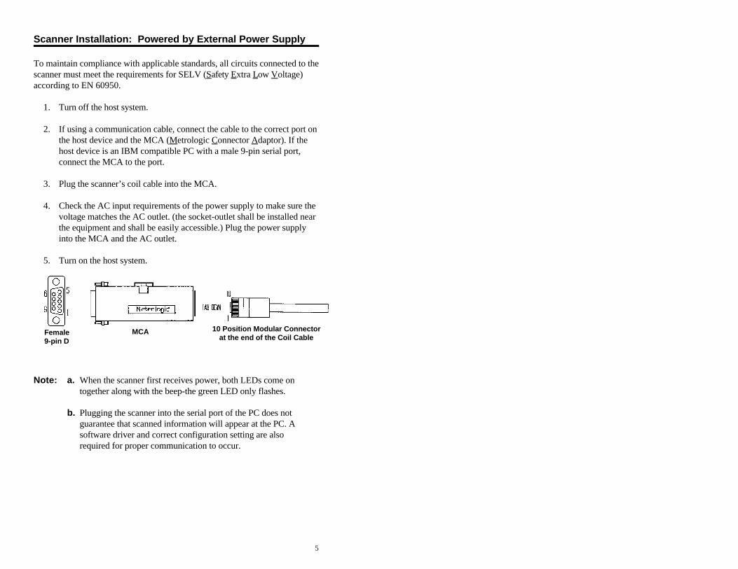
MCA Female9-pin D
10 Position Modular Connectorat the end of the Coil Cable
Scanner Installation: Powered by External Power Supply
To maintain compliance with applicable standards, all circuits connected to thescanner must meet the requirements for SELV (Safety Extra Low Voltage)according to EN 60950.
1. Turn off the host system.
2. If using a communication cable, connect the cable to the correct port onthe host device and the MCA (Metrologic Connector Adaptor). If thehost device is an IBM compatible PC with a male 9-pin serial port,connect the MCA to the port.
3. Plug the scanner’s coil cable into the MCA.
4. Check the AC input requirements of the power supply to make sure thevoltage matches the AC outlet. (the socket-outlet shall be installed nearthe equipment and shall be easily accessible.) Plug the power supplyinto the MCA and the AC outlet.
5. Turn on the host system.
Note: a. When the scanner first receives power, both LEDs come on together along with the beep-the green LED only flashes.
b. Plugging the scanner into the serial port of the PC does notguarantee that scanned information will appear at the PC. Asoftware driver and correct configuration setting are alsorequired for proper communication to occur.

6
MCA
Female 9-pin D
MCA
MS6720 coil cable MCA host
Scanner Installation: Powered by Host Device
If the host system supplies +5VDC power to the scanner, reposition the internal jumperwithin the MCA (Metrologic Connector Adaptor) before connecting the scanner to thehost device. In addition, plug the 4 position ground jumper into the power supplyconnector located on the side of the MCA.
1. Make sure the MCA is not connected to the scanner,communication cable or host and unfasten the case.
2. Reposition the shunt on JP1 to pins 1 and 2 andclose the case.
Note: The factory setting of jumper 1 (JP1) is on pins 2and 3. To direct power for the scanner from thehost device, position the jumper on pins 1 and 2.
3. Plug the 4 position ground jumper into the powersupply connector.
4. Turn off the host system.
5. If using a communication cable, connect thecable to the correct port on the host device and the MCA. If the host device is an IBM compatible with a male 9-pin serial port,connect the MCA to the port. There is an optional cable (MLPN 51236) that is avail-able for IBM PC applications where theMCA will not fit at the back of the computer.
6. Plug the scanner’s coil cable into the MCA.
7. Turn on the host system.
7
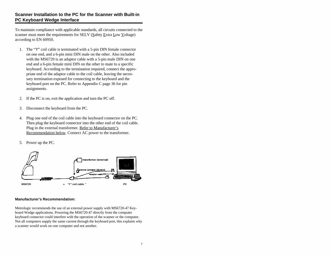
MS6720 »» “Y” coil cable ºº PC
Scanner Installation to the PC for the Scanner with Built-inPC Keyboard Wedge Interface
To maintain compliance with applicable standards, all circuits connected to thescanner must meet the requirements for SELV (Safety Extra Low Voltage)according to EN 60950.
1. The “Y” coil cable is terminated with a 5-pin DIN female connector on one end, and a 6-pin mini DIN male on the other. Also includedwith the MS6720 is an adaptor cable with a 5-pin male DIN on oneend and a 6-pin female mini DIN on the other to mate to a specifickeyboard. According to the termination required, connect the appro-priate end of the adaptor cable to the coil cable, leaving the neces-sary termination exposed for connecting to the keyboard and thekeyboard port on the PC. Refer to Appendix C page 36 for pinassignments.
2. If the PC is on, exit the application and turn the PC off.
3. Disconnect the keyboard from the PC.
4. Plug one end of the coil cable into the keyboard connector on the PC.Then plug the keyboard connector into the other end of the coil cable.Plug in the external transformer. Refer to Manufacturer’sRecommendation below. Connect AC power to the transformer.
5. Power up the PC.
Manufacturer’s Recommendation:
Metrologic recommends the use of an external power supply with MS6720-47 Key-board Wedge applications. Powering the MS6720-47 directly from the computerkeyboard connector could interfere with the operation of the scanner or the computer.Not all computers supply the same current through the keyboard port, this explains whya scanner would work on one computer and not another.

8
The MS6720 Stand
The stand for the MS6720 is ergonomic and application friendly. The mounting wasdesigned to provide an adequate distance for scanning between the scanner face and thecounter top at all times. When fully tilted, the face of the scanner remains a full fiveinches from the counter. The stand comes preassembled so it can be attached to thework surface with minimum effort (also included is the wall mount clip). The instruc-tions for use of the wall mount clip are included with the general assembly instructionsfor the stand. Listed below are the component parts of the MS6720 stand kits.
1) Complete Stand Kit:MLPN 45967
Kit includes: MLPN 45965 (counter top stand)
MLPN 45969 (weighted base)MLPN 45978 (wall clip)10-32 x 3/8" flat head screws#10 x 1" flat head wood screws
2) Counter top Stand Kit: (for securing directly to a counter top ONLY)
MLPN 45965Kit includes:each: parts a, b, c, d as shown
#10 x 1" flat head wood screws
3) Wall Mount Kit: (for directly to a wall ONLY)
MLPN 45966Kit includes:part (a) as shown45978 (wall clip)#10 x 1" flat head wood screws

Green and Red LEDWhen the red LED is on, this indicates that thelaser is on. When the green LED flashes on,the scanner has read a bar code successfully.When the green light turns off, communica-tion to the host is complete. The green LEDblinks while the scanner is waking up from anIR sensor timeout. The LED’s are also usedas diagnostic indicators and mode indicators.Refer to pages 10-12 for details.
Output WindowLaser light emits from this aperture.
º
Coil CableThis cable is terminated with a 10-pin modular connector, which attaches tothe MCA951. The Keyboard Wedge unit has a “Y” coil cable terminated witha 5-pin female on one end, a 6-pin male and a 4-pin locking connector forpower input (power jumper). An adaptor is included with a 5-pin male DINon one end and a 6-pin female mini DIN on the other to mate to a specifickeyboard. Refer to Appendix C page 36 for pin assignments.
Adjustable StandDesigned to provide an adequatedistance for scanning between thescanner face and counter at alltimes. When fully tilted, the faceof the scanner remains a full fiveinches from the counter. Refer topage 8 for available kits.
»
9
Scanner Parts

10
Audible Indicators
When the MS6720 scanner is in operation, it provides audible feedback.These sounds indicate the status of the scan and scanner. Four settings areavailable for the tone of the beep. To change the tone, refer to the Program-ming Guide section: Beeper Tones.
One Beep
*When the scanner first receives power, both LEDs come on together along with the beep-the green LED only flashes. After the scanner performs this startup sequence, thescanner is ready to scan.
When the scanner successfully reads a bar code, the green lightwill flash and beep once (if programmed to do so). If the scannerdoes not beep once and the green light does not flash, then the
bar code has not been successfully read.
Razzberry Tone
This tone is a failure indicator. Refer to failure modes page 11.
Three Beeps - after power up
***When entering the program mode, the green LED will flashwhile the scanner simultaneously beeps three times. The greenLED will continue to flash until the unit exits program mode.Upon exiting program mode, the scanner will beep three timesand the green LED will stop flashing. When configured, 3 beepscan also indicate a communications timeout during normalscanning mode.
11
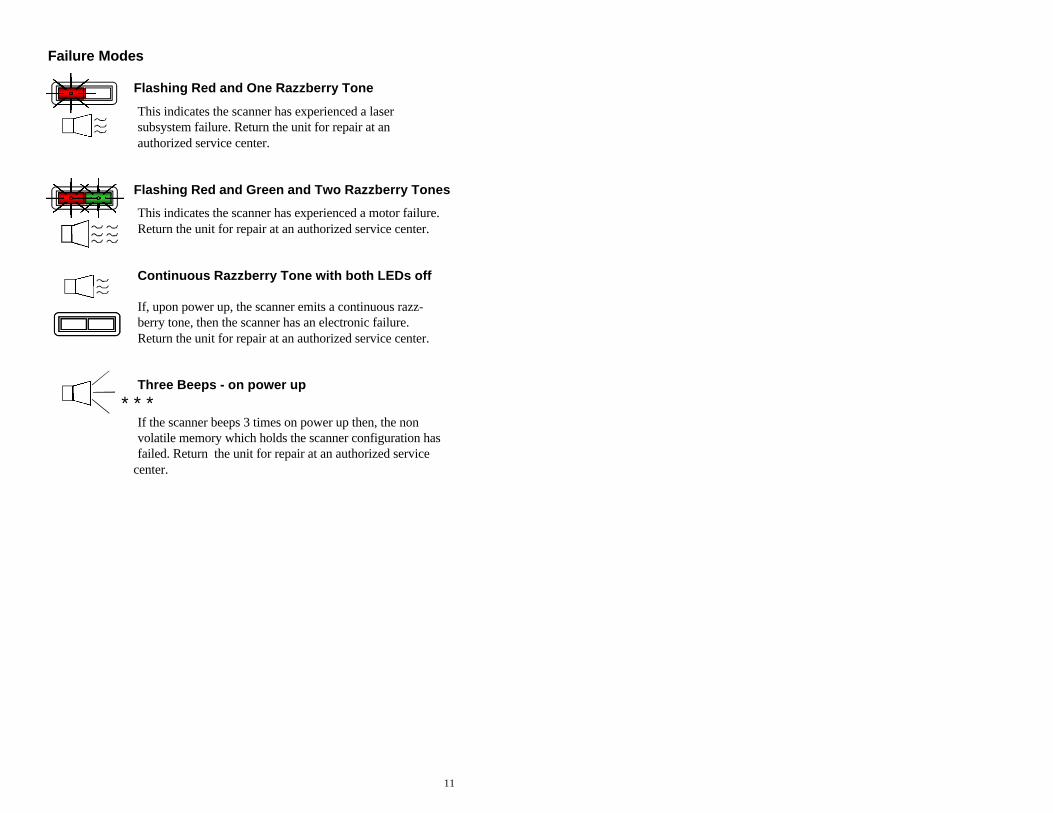
Failure Modes
Flashing Red and One Razzberry Tone
This indicates the scanner has experienced a lasersubsystem failure. Return the unit for repair at anauthorized service center.
Flashing Red and Green and Two Razzberry Tones
This indicates the scanner has experienced a motor failure.Return the unit for repair at an authorized service center.
Continuous Razzberry Tone with both LEDs off
If, upon power up, the scanner emits a continuous razz-berry tone, then the scanner has an electronic failure.Return the unit for repair at an authorized service center.
Three Beeps - on power up
***If the scanner beeps 3 times on power up then, the nonvolatile memory which holds the scanner configuration hasfailed. Return the unit for repair at an authorized service
center.

12
Visual Indicators
There are a red LED and a green LED on the scanner. When the scanner is on, theflashing or stationary activity of the LEDs indicates the status of the scan and scan-ner.
No Red or Green LED
There are two reasons why the LEDs will not be illuminated:
1.) If the scanner is receiving power and the LEDs are not on, thenthe scanner has been dormant for a specified time and the laserhas turned off. To reactivate the unit, pass an object throughthe scan field.
2.) If the scanner is not receiving power from the host or trans-former, then the LEDs will not be on.
Steady Red
When the laser is on, the red LED is also on. The red LED willremain on until the scanning period has expired.
Steady Red and Single Green Flash
When the scanner successfully reads a bar code, the green LED will flash then beep once. If the green LED does not flash or the
scanner does not beep once, then the bar code has not been suc-cessfully read.
Steady Red and Steady Green
After a successful scan, the scanner transmits the data to the hostdevice. If the host is not ready to accept the information, the scan-ner’s green LED will remain on until the data can be transmitted.The red LED will turn off when the scanning period expires.
Steady Red and Flashing Green
This indicates the scanner is in program mode. A razzberry toneindicates that an invalid bar code has been scanned in this mode.
Steady Green
This indicates the scanner may be waiting for communication fromthe host.
Flashing Green This indicates the scanner is waking up from a dormant state inresponse to an IR sensor activation. Refer to page 18.

13
Label
Each scanner has a label located on the bottom of the unit. This label containsinformation such as the model number, date of manufacture, serial number, and approvals. This label also notes that the device is a CDRHClass IIa laser product. The following is an example of this label:

14
Depth of Field Specifications
Normal Depth of Field

15
Short Depth of Field
16
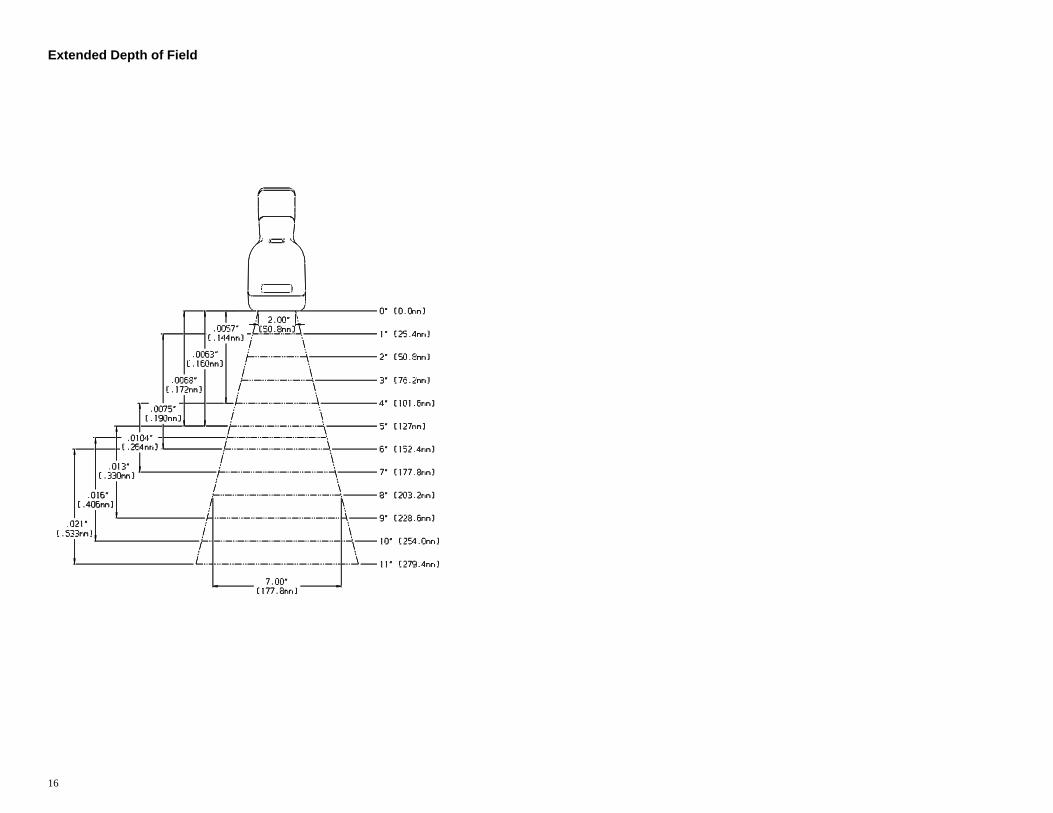
Extended Depth of Field

17
Optional Depth of Field
18
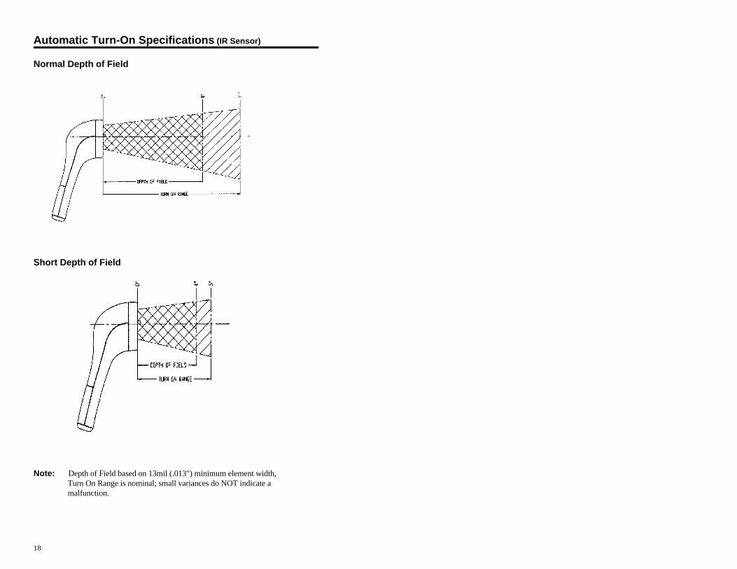
Automatic Turn-On Specifications (IR Sensor)
Normal Depth of Field
Short Depth of Field
Note: Depth of Field based on 13mil (.013") minimum element width, Turn On Range is nominal; small variances do NOT indicate a malfunction.

19
Scan Pattern Specifics
Projection Axis
The scan pattern of the MS6720 exits straight out of the scanner. This featurewas purposefully designed to provide pointing efficiency in the hand held mode and instinctive positioning in the fixed presentation mode.
Omnidirectional Scan Volume
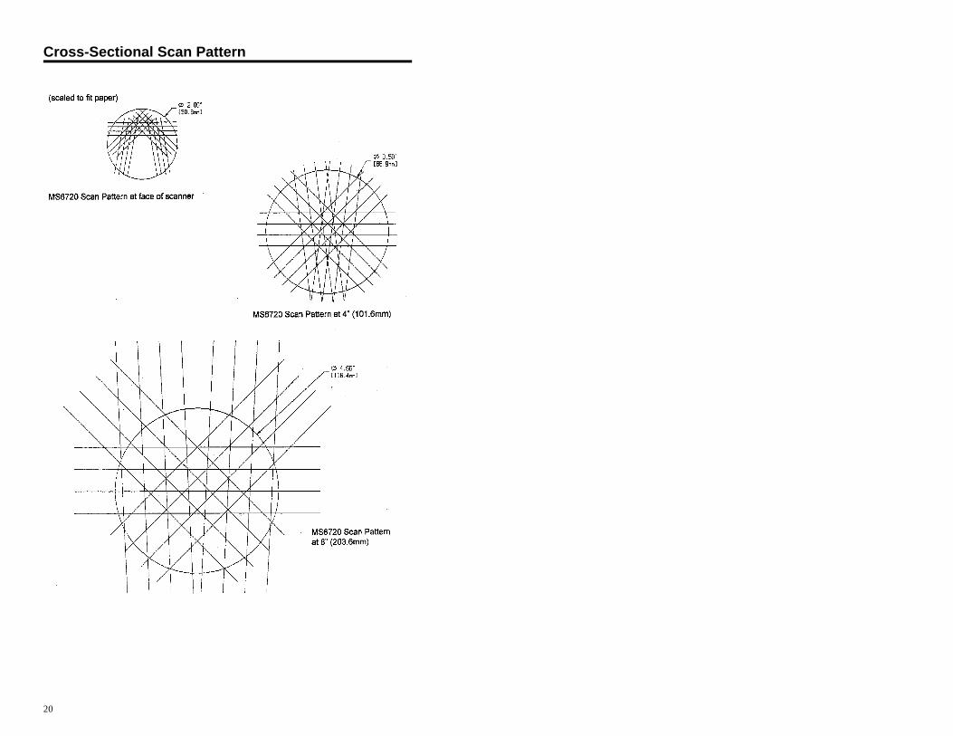
Note: The above scan volume shows omnidirectional volume. This volume does not reflect the entire length of all the laser lines. (Please refer to the Cross-Sectional Pattern in this section, page 20).
20
Cross-Sectional Scan Pattern

21
Maintenance
Smudges and dirt can interfere with the proper scanning of a bar code.Therefore, the output window will need occasional cleaning.
1. Spray glass cleaner onto lint free, non-abrasive cleaning cloth.
2. Gently wipe the scanner window.
22
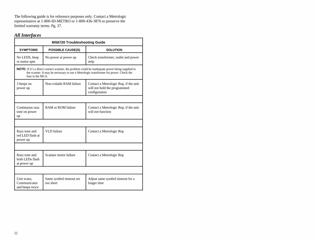
The following guide is for reference purposes only. Contact a Metrologicrepresentative at 1-800-ID-METRO or 1-800-436-3876 to preserve thelimited warranty terms. Pg. 37.
All Interfaces
MS6720 Troubleshooting Guide
SYMPTOMS POSSIBLE CAUSE(S) SOLUTION
No LEDS, beep No power at power up Check transformer, outlet and poweror motor spin strip
NOTE: If it’s a direct connect scanner, the problem could be inadequate power being supplied to the scanner. It may be necessary to use a Metrologic transformer for power. Check the fuse in the MCA.
3 beeps on Non-volatile RAM failure Contact a Metrologic Rep, if the unitpower up will not hold the programmed
configuration
Continuous razz RAM or ROM failure Contact a Metrologic Rep, if the unittone on power will not functionup
Razz tone and VLD failure Contact a Metrologic Repred LED flash atpower up
Razz tone and Scanner motor failure Contact a Metrologic Repboth LEDs flashat power up
Unit scans, Same symbol timeout set Adjust same symbol timeout for aCommunicates too short longer timeand beeps twice

23
All Interfaces continuedSYMPTOMS POSSIBLE CAUSE(S) SOLUTION
Unit goes to IR sensor used to wake up Adjust scanner positioning so that thesleep and does the scanner is always IR senses an object when a bar codenot wake up sensing an object is presented. For example; point to
the ceiling and then back to the object.
Disable IR sleep mode
Unit scans bar wake up requires full Disable IR sleep modecode too slowly motor spin up for operationupon waking up
NOTE: Disabling the IR sleep mode allows the scanner to respond to bar codes quicker

24
SYMPTOMS
The unit powers up properly, lasers come on, but the unit does not scan and does notbeep when a bar code is presented
POSSIBLE CAUSE(S)/SOLUTION(S)
Improper settings can be the cause for a scanner not to scan. The following would betypical examples:
1. Scanning a particular symbology that is not enabled. (UPC/EAN, Code 39, Interleaved 2 of 5, Code 93, Code 128 and Codabar are enabled by default.) Verify that the type of bar code being read has been selected.
2. The scanner has been programmed for a character length lock, or a minimum length and the bar code being scanned does not satisfy the programmed criteria. Verify that the bar code that is being scanned falls into the criteria. (Typical of Non-UPC/EAN codes.)
3. The scanner scans a bar code but the scanner locks up (green LED comes on and stays on) after the first scan. The scanner is configured to support some form of host handshaking but is not receiving the signal. If the scanner is setup to support ACK/NAK, RTS/CTS, XON/XOFF or D/E, verify that the host cable and host are supporting the handshaking properly.
4. The scanner scans and transmits but the data is not correct at the host. Verify that the scanner’s data format matches that required by the host. Make sure that the scanner is connected to the proper host port.
SYMPTOMS
Scanner beeps at some bar codes and NOT for others of the same bar code symbology
POSSIBLE CAUSE(S)/SOLUTION(S)
1. The print quality of the bar code is suspect.
2. The aspect ratio of the bar code is out of tolerance.
3. The bar code may have been printed incorrectly. (check digit/character/or border problem.)

25
Keyboard Wedge OnlySYMPTOMS POSSIBLE CAUSE(S) SOLUTION
Unit scans the Configuration is not correct Make sure the scanner is configuredbar code but for keyboard wedge mode - Sectionthere is no data F of the ScanSelect Guide (MLPN
2186)
Unit scans but Configuration is not correct Make sure that the proper PC typedata is not AT, PS2, XT is selectedcorrect
verify correct country code and dataformatting are selected
Adjust inter character delay
Unit is Configuration is not correct Increase the inter scan code delaytransmitting settingeach charactertwice Adjust whether the F0 break is
transmitted. It may be necessary totry this in both settings.
Alpha characters Computer is in Caps Lock Enable Caps Lock detect setting ofshow as lower mode the scanner to detect whether PC iscase operating in Caps Lock
Everything These characters may not be Try operating the scanner in Altworks except for supported by that country’s modea couple of key look up tablecharacters
26
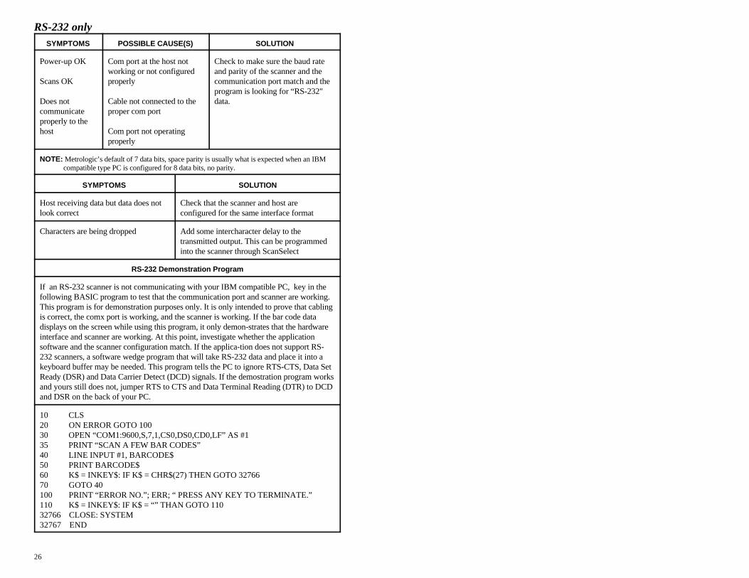
RS-232 onlySYMPTOMS POSSIBLE CAUSE(S) SOLUTION
Power-up OK Com port at the host not Check to make sure the baud rate
Scans OK properly communication port match and the
Does not Cable not connected to the data.communicate proper com portproperly to thehost Com port not operating
working or not configured and parity of the scanner and the
properly
program is looking for “RS-232"
NOTE: Metrologic’s default of 7 data bits, space parity is usually what is expected when an IBM compatible type PC is configured for 8 data bits, no parity.
SYMPTOMS SOLUTION
Host receiving data but data does not Check that the scanner and host arelook correct configured for the same interface format
Characters are being dropped Add some intercharacter delay to thetransmitted output. This can be programmedinto the scanner through ScanSelect
RS-232 Demonstration Program
If an RS-232 scanner is not communicating with your IBM compatible PC, key in thefollowing BASIC program to test that the communication port and scanner are working.This program is for demonstration purposes only. It is only intended to prove that cablingis correct, the comx port is working, and the scanner is working. If the bar code datadisplays on the screen while using this program, it only demon-strates that the hardwareinterface and scanner are working. At this point, investigate whether the applicationsoftware and the scanner configuration match. If the applica-tion does not support RS-232 scanners, a software wedge program that will take RS-232 data and place it into akeyboard buffer may be needed. This program tells the PC to ignore RTS-CTS, Data SetReady (DSR) and Data Carrier Detect (DCD) signals. If the demostration program worksand yours still does not, jumper RTS to CTS and Data Terminal Reading (DTR) to DCDand DSR on the back of your PC.
10 CLS20 ON ERROR GOTO 10030 OPEN “COM1:9600,S,7,1,CS0,DS0,CD0,LF” AS #135 PRINT “SCAN A FEW BAR CODES”40 LINE INPUT #1, BARCODE$50 PRINT BARCODE$60 K$ = INKEY$: IF K$ = CHR$(27) THEN GOTO 3276670 GOTO 40100 PRINT “ERROR NO.”; ERR; “ PRESS ANY KEY TO TERMINATE.”110 K$ = INKEY$: IF K$ = “” THAN GOTO 11032766 CLOSE: SYSTEM32767 END

27
Applications and Protocols
The model number on each scanner includes the scanner number andcommunications protocol.
Scanner Version Identifier Communication Protocol(s)
6720 9 OCIA (OCIA)6720 11 IBM (46XX)6720 14 RS-232 (232)6720 15 Light Pen Emulation (LTPN)6720 47 Keyboard Wedge (KBW)
The MS6720 Hand-Held Laser Scanner with Built-in PC Keyboard Wedge Interface is designed to be used for keyboard emulation only. However,many RS-232 programmable functions that are available in other Metrologic scanners are also available as keyboard wedge functions.The most important selectable options specific to the key-board wedge are the following:
Keyboard Type
! ** AT (includes IBM PS2 models 50, 55, 60, 80)®
! XT! IBM PS2 (includes models 30, 70, 8556)
Keyboard Country Type
! ** USA ! United Kingdom! French ! German! Italian ! Spanish! Belgium ! Swiss
**Default setting. Refer to Appendix B pages 30 - 33 for default settings.Refer to ScanSelect Scanner Programming Guide (MLPN 2186) forinformation on how to change the default settings.

28
Appendix A
Design Specifications
Application: Fixed Projection/Hand-Held Laser Bar CodeScanner
Max. Radiant Power: 0.681 Milliwatts (PEAK)Light Source: VLD 675 ± 5nmCDRH: Class IIa laser productCE: EN 60950: 1993, EN 60825-1:1994/A11:1996,
Laser Class 1, EN 55022:1987 Class A, EN 55082-1:1992, IEC 801-2:1991 8kVAD, IEC100-4-3:1995 3V/m IEC 801-4:1988 1kV Power Lines
EMI: FCC Class A
Mechanical
Dimensions: 110mm L x 75mm W x 160mm HWeight: 450 gramsTermination: ~ 1 meter retracted coil cable
Electrical
Input Voltage: 5VDC ± .25VPower : 1.1 wattOperating Current : 225 mA typical @5VDC (468x - 300mA)Standby Current: 74 mils (468x - 165mils)DC Transformers: Class 2; 5VDC @300mA

29
Operational
Depth of Field: 0" - 4"; 0"- 8" (programmable)0 - 101.6mm; 0 - 203.2mm
Scan Speed: 1000 scan lines per secondScan Pattern: 5 fields of 4 parallel linesScan Lines: 20Min Bar Width: 5.2 milIndicators (LED): red = laser on, ready to scan
green = good read, decodingBeeper Operation: 3 tones or no beepMaintenance: Clean output window periodicallyDecode Capability: Autodiscriminates all standard bar codes;
for other symbologies call Metrologic System Interfaces: Keyboard Wedge, RS-232, OCIA, Light Pen, IBM
46xxPrint Contrast: 35% minimum reflectance differenceRoll, Pitch, Yaw: 360E, 60E, 60E
Environmental
Storage Temperature: -40EC to 60EC (-40EF to 140EF) Operating Temperature: 0EC to 35EC (32EF to 95EF) Humidity: 5% to 95% relative humidity, non-condensingLight Levels: Up to 300 LUXVentilation: None requiredShock: 1m. (40") dropContaminants: Sealed to resist airborne particulate contaminants
This Metrologic product may be covered by one or more of the following U.S.patents:
5, 073,702, 5,115,333, 5, 216,232, 5,484,992, 5,525,789, 5,557,093,5,591,953, 5,616,908.
Specifications subject to change without notice.

30
Appendix B
Default Settings
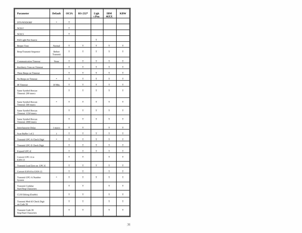
Many functions of the scanner can be "programmed" - that is, enabled ordisabled. The scanner is shipped from the factory programmed to a set ofdefault conditions. The default parameter of the scanner has an asterisk ( * ) inthe charts on the following pages. If an asterisk is not in the default columnthen the default setting is Off or Disabled. Every communication does notsupport every parameter. If the communication supports a para-meter listed inthe charts on the following pages, a check mark will appear.
Parameter Default OCIA RS-232* Ligh IBM KBWt Pen 46XX
UPC/EAN * T T T T T
Code 128 * T T T T T
Code 93 * T T T T T
Codabar * T T T T T
Interleaved 2 of 5 (ITF) * T T T T T
MOD 10 Check on ITF T T T T T
Code 11 T T T T T
Code 39 * T T T T T
Full ASCII Code 39 T T T T T
MOD 43 Check on Code 39 T T T T T
MSI-Plessey T T T T T
MSI-Plessey 10/10 Check Digit T T T T T
MSI-Plessey MOD 10 Check * T T T T TDigit
MECCA T T T T T
Paraf Support T T T T T
ITF Symbol Lengths Variable T T T T T
Minimum Symbol Length 04 T T T T T
Symbol Length Lock None T T T T T
Bars High as Code 39 * T
Spaces High as Code 39 T
Bars High as Scanned T
Spaces High as Scanned T
DTS/SIEMENS T
31
Parameter Default OCIA RS-232* Ligh IBM KBWt Pen 46XX
DTS/NIXDORF * T
NCR F T
NCR S T
Poll Light Pen Source T
Beeper Tone Normal T T T T T
Beep/Transmit Sequence Before T T T T TTransmit
Communication Timeout None T T T T T
Razzberry Tone on Timeout T T T T T
Three Beeps on Timeout T T T T T
No Beeps on Timeout * T T T T T
IR Timeout 10 Min. T T T T T
Same Symbol Rescan T T T T TTimeout: 200 msecs
Same Symbol Rescan * T T T T TTimeout: 500 msecs
Same Symbol Rescan T T T T TTimeout: 1250 msecs
Same Symbol Rescan T T T T TTimeout: 2000 msecs
Intercharacter Delay 1 msecs T T T T
Scan Buffer 1 of 2 1 T T T T T
Transmit UPC-A Check Digit * T T T T T
Transmit UPC-E Check Digit T T T T T
Expand UPC-E T T T T T
Convert UPC-A to T T T TEAN-13
Transmit Lead Zero on UPC-E T T T T T
Convert EAN-8 to EAN-13 T T T T
Transmit UPC-A Number * T T T T TSystem
Transmit Codabar T T T TStart/Stop Characters
CLSI Editing (Enable) T T T T
Transmit Mod 43 Check Digit T T T Ton Code 39
Transmit Code 39 T T T TStop/Start Characters

32
Parameter Default OCIA RS-232* Ligh IBM KBWt Pen 46XX
Transmit Mod 10/ITF T T T T
Transmit MSI-Plessey Check T T T TCharacters
Parity Space T
Baud Rate 9600 T
8 Data Bits T
7 Data Bits * T
Transmit Sanyo ID Characters T T
Nixdorf ID T T
Shell Schulmberger T TFormatting
UPC Prefix T T
UPC Suffix T T
Transmit AIM ID Characters T T
STX Prefix T T
ETX Suffix T T
Carriage Return * T T
Line Feed * T T
Tab Prefix T T
Tab Suffix T T
"DE" Disable Command T
"FL" Laser Enable Command T
DTR Handshaking Support T
RTS/CTS Handshaking T
Character RTS/CTS * T
Message RTS/CTS T
XON/XOFF Handshaking T
ACK/NAK T
Two Digit Supplements T T as T Tcode39
Five Digit Supplements T T as T Tcode39
Bookland T T as T Tcode39

33
Parameter Default OCIA RS-232* Ligh IBM KBWt Pen 46XX
977 (2 digit) Supplemental T T T T TRequirement
Supplements are not Required * T T T T T
Two Digit Redundancy * T T T T T
Five Digit Redundancy T T T T T
200 msec to Find Supplement T T T T T
100 msec to Find Supplement * T T T T T
Coupon Code 128 T T as T Tcode39

34
Appendix C
Pin Assignments
Cable Pin Assignments for the Coil Cable
The MS6720 scanners are terminated to a 10 position shielded modularconnector. All of the coil cables (MLPN 44530) for the MS6720 scanner areterminated the same. The difference between versions is the end of the cablegoing into the scanner. This connector plugs into different “J” positions onvarious computer/interface boards. Since each computer/interface board isdifferent, the output signals are different.
Version “9” (OCIA) Version “11” (46XX)
Pin Function Pin Function
1 Power/Signal Ground 1 Power/Signal Ground2 RDATA 2 RS-232 Transmit Output3 RDATA Return 3 RS-232 Receive Input4 Clock In 4 RTS Output5 Clock In Return 5 CTS Input6 Clock Out 6 IBM 46XX Transmit7 Clock Out Return 7 IBM 46XX Receive8 No Connection 8 No Connection9 +5 VDC Power to Scanner 9 +5 VDC Power to Scanner10 OCIA Shield Ground 10 Shield Ground
Version “14” (232) Version “15” (LTPN)
PinFunction Pin Function
1 Power/Signal Ground 1 Power/Signal Ground2 RS-232 Transmit Output 2 RS-232 Transmit Output3 RS-232 Receive Input 3 RS-232 Receive Input4 RTS Output 4 RTS Output5 CTS Input 5 CTS Input6 DTR Input 6 Light Pen Source +5V7 DSR Output 7 Light Pen Data8 No Connection 8 No Connection9 +5 VDC Power to Scanner 9 +5 VDC Power to Scanner
10 Shield Ground 10 Shield Ground

35
Pin Assignments for the MCA951 (DEC9S)
Located on the MCA is a 9-pin female D-type connector used to connect theMCA to the host device. The output signals on the 9-pin host end of the MCAare dependent upon which version of the scanner that is being used. Thefollowing is a list of the pin assignments for the different versions:
Version “9” (OCIA) Version “11” (46XX)
Pin Function Pin Function
1 OCIA Shield Ground 1 Shield Ground2 RDATA 2 RS-232 Transmit Output3 RDATA Return 3 RS-232 Receiver Input4 Clock Out 4 IBM 4680 -B5 Power/Signal Ground 5 Power/Signal Ground6 Clock Out Return 6 IBM 4680 +A7 Clock In Return 7 Clear to Send Input8 Clock In 8 Request to Send Output*9 +5VDC Power to Scanner *9 +5VDC Power to Scanner
Version “14” (232) Version “15” (LTPN)
Pin Function PinFunction
1 Shield Ground 1 Shield Ground2 RS-232 Transmit Output 2 RS-232 Transmit Output3 RS-232 Receiver Input 3 RS-232 Receive Input4 Data Terminal Ready Input 4 Light Pen Source (+5V Input)5 Power/Signal Ground 5 Power/Signal Ground6 Data Set Ready Output 6 Light Pen Data (Output)7 Clear to Send Input 7 Clear to Send (Input)8 Request to Send Output 8 Request to Send (Output)9 +5VDC Power to Scanner *9 +5VDC Power to Scanner
*When the host supplies power to the scanner, this is the pin assignment forthe +5VDC for the scanner. If, in the application, the host device will supplythe power necessary for the scanner, reposition an internal jumper within theMCA and plug the 4 position ground jumper to the power supply connector forFCC and ESD purposes. (Refer to Scanner Installation: Powered byExternal Power Supply page 5).
36
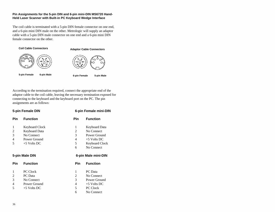
Coil Cable Connectors
5-pin Female 6-pin Male
Adaptor Cable Connectors
6-pin Female 5-pin Male
Pin Assignments for the 5-pin DIN and 6-pin mini-DIN MS6720 Hand-Held Laser Scanner with Built-in PC Keyboard Wedge Interface
The coil cable is terminated with a 5-pin DIN female connector on one end,and a 6-pin mini DIN male on the other. Metrologic will supply an adaptorcable with a 5-pin DIN male connector on one end and a 6-pin mini DINfemale connector on the other.
According to the termination required, connect the appropriate end of theadaptor cable to the coil cable, leaving the necessary termination exposed forconnecting to the keyboard and the keyboard port on the PC. The pinassignments are as follows:
5-pin Female DIN 6-pin Female mini-DIN
Pin Function Pin Function
1 Keyboard Clock 1 Keyboard Data2 Keyboard Data 2 No Connect3 No Connect 3 Power Ground4 Power Ground 4 +5 Volts DC5 +5 Volts DC 5 Keyboard Clock
6 No Connect
5-pin Male DIN 6-pin Male mini-DIN
Pin Function Pin Function
1 PC Clock 1 PC Data2 PC Data 2 No Connect3 No Connect 3 Power Ground4 Power Ground 4 +5 Volts DC5 +5 Volts DC 5 PC Clock
6 No Connect
37
Appendix D
Warranty and Disclaimer
Limited Warranty
Products manufactured by Metrologic have a 2-year limited warranty fromdate of manufacture.
This warranty is limited to repair, replacement or refund at Metrologic’sdiscretion. Faulty equipment must be returned to the Metrologic facility inBlackwood, New Jersey or Puchheim, Germany. To do this, contactMetrologic Customer Service/Repair for a Returned Material Authorization(RMA) number.
In the event that it is determined that the equipment failure is covered under thewarranty, Metrologic shall, as its sole option, repair, replace with a functionallyequivalent unit, or refund an amount equal to the purchase price to the originalpurchaser, whether distributor, dealer/reseller, or retail consumer, and return theequipment to the customer without charge for service or return freight.
This limited warranty does not extend to any Product which, in the sole judge-mentof Metrologic, has been subjected to misuse, neglect, improper installation oraccident, nor does it extend to any Product which has been repaired or altered byanyone who is not a Metrologic authorized representative.
THIS LIMITED WARRANTY, EXCEPT AS TO TITLE, IS IN LIEU OF ALL OTHERWARRANTIES, EXPRESS OR IMPLIED, INCLUDING MERCHANTABILITY ORFITNESS FOR ANY PARTICULAR PURPOSE, ARISING BY LAW, CUSTOM ORCONDUCT. THE RIGHTS AND REMEDIES PROVIDED HEREIN ARE EXCLUSIVEAND IN LIEU OF ANY OTHER RIGHTS OR REMEDIES. IN NO EVENT SHALLMETROLOGIC BE LIABLE FOR INDIRECT, INCIDENTAL, OR CONSEQUENTIALDAMAGES, INCLUDING, WITHOUT LIMITATION, ANY INJURY TO PROPERTYOR PERSON OR EFFECT ON BUSINESS OR PROFIT, AND IN NO EVENT SHALLANY LIABILITY OF METROLOGIC EXCEED THE ACTUAL AMOUNT PAID TOMETROLOGIC FOR THE PRODUCT.
Metrologic Instruments, Inc. Customer Service Department 90 Coles Road 1-800-ID-METRO (1-800-436-3876)Blackwood, NJ 08012 TEL: 609-228-8100
FAX: 609-228-6673Metrologic Instruments GmbHDornierstrasse 282178 Puchheim b. Munich, GermanyTEL: 49-89-89019-0 FAX: 49-89-89019-200

38
DisclaimerMetrologic Instruments, Inc. and the author or authors make no claims or warranties with respectto the contents or accuracy of this publication, or the product it describes, including any warrantiesof fitness or merchantability for a particular purpose. Any stated or expressed warranties are inlieu of all obligations or liability for any damages, whether special, indirect, or consequential,arising out of or in connection with the use of this publication or the product it describes.Furthermore, the right is reserved to make any changes to this publication without obligation tonotify any person of such changes. Metrologic also reserves the right to make any changes to theproduct described herein.
Exclusion des responsabilitésMetrologic Instruments, Inc. et le/les auteur(s) ne sont ni garants, ni responsables pour l-'exhaustivité et la correction des informations contenues dans cette brochure - que ce soit r-elativement à leur teneur et à l' exactitude - ou pour le produit qui y est décrit. Ils ne sont en outreresponsables d'aucune garantie de propriété ou de qualité pour un usage particulier. Toutes lesassurances nommées ou exprimées excluent toute garantie ou responsabilité pour les dommagesspéciaux, indirects ou des suites de l'utilisation de cette brochure ou du produit qui y est décritrespectivement. en rapport avec l'emploi de cette brochure et du produit qui y est décrit. Il leur estégalement réservé le droit de procéder à des modifications de cette brochure sans avoir à en avertirqui que ce soit. Metrologic se réserve en outre le droit de procéder à des modifications du produitqui y est décrit.
HaftungsausschlußMetrologic Instruments, Inc. und der/die Autor(en) übernehmen keinerlei Gewähr und haften nichtfür die Richtigkeit im Hinblick auf Inhalt oder Genauigkeit der Angaben dieser Veröffentlichungoder des hierin beschriebenen Produkts. Sie übernehmen ebenso keinerlei Eignungsgarantie oderGewährleistung durchschnittlicher Qualität für einen bestimmten Zweck. Alle benannten oderausdrücklichen Zusicherungen schließen sämtliche Verpflichtungen oder Haftungen aus jeglichemSchaden aus, ganz gleich ob speziell, indirekt oder als Folge der Verwendung dieserVeröffentlichung oder des hierin beschriebenen Produkts bzw. in Zusammenhang mit derVerwendung dieser Veröffentlichung oder des hierin beschriebenen Produkts. Darüber hinaus wirddas Recht vorbehalten, Änderungen an dieser Veröffentlichung vorzunehmen ohne dieVerpflichtung, irgend jemanden über solche Änderungen zu unterrichten. Metrologic behält sichferner das Recht vor, Änderungen an dem hierin beschriebenen Produkt vorzunehmen.
Esclusione della responsabilitàLa Metrologic Instruments, Inc. e l’autore/gli autori non assumono nessuna garanzia e nonrispondono della correttezza per quanto riguarda il contenuto o la precisione di quanto indicato nelpresente Manuale o del prodotto in esso descritto. Neppure essi assumono una garanzia perl’idoneità o una garanzia della qualità media per un determinato scopo. Tutte le garanzie citate ofatte espressamente escludono qualsiasi obbligo o responsabilità derivanti da qualsiasi danno,indipendentemente dal fatto che questo obbligo/questa responsabilità risulti in particolare, i-ndirettamente o come conseguenza dall’uso del presente Manuale o del prodotto in esso descrittooppure se è legato/a all’uso del presente Manuale o del prodotto in esso descritto. Inoltre ci siriserva il diritto di modificare il presente Manuale senza essere obbligati ad informare personaalcuna circa dette modifiche. Metrologic si riserva il diritto di apportare modifiche al prodottodescritto nel presente Manuale.

39
Appendix E
Notices
NoticeThis equipment has been tested and found to comply with limits for a Class A digital device,pursuant to Part 15 of the FCC Rules. These limits are designed to provide reasonable protectionagainst harmful interference when the equipment is operated in a commercial environment. Thisequipment generates, uses and can radiate radio frequency energy and, if not installed and used inaccordance with the instruction manual, may cause harmful interference to radio communications.Operation of this equipment in a residential area is likely to cause harmful interference, in whichcase the user will be required to correct the interference at his own expense. Any unauthorizedchanges or modifications to this equipment could void the users authority to operate this device.
NoticeThis digital apparatus does not exceed the Class A limits for radio noise emissions from digitalapparatus set out in the Radio Interference Regulations of the Industry and Canada.
CautionUse of controls or adjustments or performance of procedures other than those specified herein mayresult in hazardous laser light. Under no circumstances should the customer attempt to service thelaser scanner. Never attempt to look at the laser beam, even if the scanner appears to benonfunctional. Never open the scanner in an attempt to look into the device. Doing so could resultin hazardous laser light exposure. The use of optical instruments with the laser equipment willincrease eye hazard.
RemarqueAprès contrôle de cet appareil, on a noté qu'il répondait aux valeurs limites de la classe A, c-onformément à la partie 15 des directives de l'administration fédérale américaine pour les t-élécommunications. Ces valeurs limites ont été prévues pour garantir une protection suffisantecontre les effets nocifs dus à l'emploi de l'appareil dans un magasin. L'appareil génère et utilise uneénergie haute fréquence et peut, s'il n'est pas installé et utilisé conformément aux instructionsmentionnées dans le guide d'utilisation, entraîner des perturbations dans la radiocommunications.L'utilisation de cet appareil dans une zone d'habitation entraînera très vraisemblablement desperturbations. Dans ce cas, l'utilisateur est tenu de remédier à ces perturbations à ses propres frais.Toute modification ou remplacement non autorisé sur cet appareil peut entraîner l'invalidité del'autorisation d'utilisation de l'appareil.
RemarqueCet appareil numérique ne va pas contre les valeurs limites pour émissions de bruits radios desappareils numérique de la classe A, conformément aux directives relatives aux perturbations desradiocommunications du ministère canadien pour l'industrie.
AttentionL'emploi de commandes, réglages ou procédés autres que ceux décrits ici peut entraîner de gravesirradiations. Le client ne doit en aucun cas essayer d'entretenir lui-même le scanner ou le laser. Neregardez jamais directement le rayon laser, même si vous croyez que le scanner est inactif.N'ouvrez jamais le scanner pour regarder dans l'appareil. Ce faisant, vous vous exposez à unerayonnement laser mortel. L'emploi d'appareils optiques avec cet équipement laser augmente lerisque d'endommagement de la vision.

40
AnmerkungNach Überprüfung dieses Geräts wurde festgestellt, daß es den Grenzwerten für Digitalgeräte derKlasse A gemäß Teil 15 der Richtlinien der US-amerikanischen Bundesbehörde für dasFernmeldewesen entspricht. Diese Grenzwerte wurden festgelegt, um einen angemessenen Schutzgegen schädliche Auswirkungen bei Einsatz des Geräts in einer Ladenumgebung zu gewähren.Das Gerät erzeugt und verwendet Hochfrequenzenergie und kann diese ausstrahlen, und kann,falls es nicht gemäß den im Bedienerhandbuch enthaltenen Anweisungen installiert und verwendetwird, zu einer Störung des Funkverkehrs führen. Der Betrieb dieses Geräts in einem Wohngebietführt höchstwahrscheinlich zu Störungen. In diesem Fall ist der Bediener verpflichtet, die Störungauf eigene Kosten zu beseitigen. Durch jegliche unerlaubte Auswechselung oder Änderung andiesem Gerät könnte die Genehmigung des Bedieners zur Verwendung dieses Geräts ungültigwerden.
AnmerkungDieses Digitalgerät verstößt nicht gegen die Grenzwerte für Funkrauschemissionen vonDigitalgeräten der Klasse A gemäß den Richtlinien für Funkstörungen des kanadischenMinisteriums für Industrie.
AchtungDie Verwendung anderer als der hierin beschriebenen Steuerungen, Einstellungen oder Verfahrenkann eine lebensgefährliche Laserstrahlung hervorrufen. Der Kunde sollte unter keinenUmständen versuchen, den Laser-Scanner selbst zu warten. Sehen Sie niemals in den Laserstrahl,selbst wenn Sie glauben, daß der Scanner nicht aktiv ist. Öffnen Sie niemals den Scanner, um indas Gerät hineinzusehen. Wenn Sie dies tun, können Sie sich einer lebensgefährlichenLaserstrahlung aussetzen. Der Einsatz optischer Geräte mit dieser Laserausrüstung erhöht dasRisiko einer Sehschädigung.
N.B.Dal controllo di questo apparecchio risulta che esso risponde ai valori limite per apparecchidigitali della classe A conf. parte 15 delle direttive sulle telecomunicazioni dell’Autorità federalestatunitense. Questi valori limite sono stati fissati per garantire una protezione adeguata contro glieffetti nocivi se questo apparecchio viene usato all’intero di un negozio. L’apparecchio genera,utilizza e può emettere energia ad alta frequenza e, se non viene installato ed utilizzatoconformemente alle indicazioni fornite nel Manuale utente, può provocare disturbi al servizioradiofonico. L’uso di questo apparecchio in zone residenziali causa molto probabilmente deidisturbi. In questo caso l’utente è obbligato ad eliminare questi disturbi a sue spese. Qualsiasisostituzione o modifica non autorizzata all’apparecchio potrebbe rendere invalida l’autorizzazionedell’utente all’uso dell’apparecchio.
N.B.Questo apparecchio digitale non supera I valori limite per l’emissione di radiorumori da parte diapparecchi digitali della classe A conformemente alle direttive per radiodisturbi del Ministerocanadese per l’Industria.
AttenzioneL’utilizzo di sistemi di controllo, di regolazioni o di procedimenti diversi da quelli decritti nelpresente Manuale può provocare dei raggi laser pericolosi per la vita. Il cliente non deveassolutamente tentare di riparare egli stesso lo scanner laser. Non guardate mai nel raggio laser,anche se credete che lo scanner non sia attivo. Non aprite mai lo scanner per guardare dentrol’apparecchio. Se tuttavia lo fate, potete esporVi a dei raggi laser pericolosi per la vita. L’uso diapparecchi ottici con questo equipaggiamento laser aumenta il rischio di danni alla vista.
41
Appendix F
Patents
“Patent Information
This METROLOGIC product may be covered by one or more of the followingU.S. Patents:
U.S. Patent No. 4,360,798; 4,369,361; 4,387,297; 4,460,120; 4,496,831;4,593,186; 4,607,156; 4,673,805; 4,736,095; 4,758,717; 4,816,660; 4,845,350; 4,896,026; 4,923,281; 4,933,538; 4,992,717; 5,015,833; 5,017,765; 5,059,779; 5,117,098; 5,124,539; 5,130,520; 5,132,525; 5,140,144; 5,149,950; 5,180,904; 5,200,599; 5,229,591; 5,247,162; 5,250,790; 5,250,791; 5,250,792; 5,262,628; 5,280,162; 5,280,164; 5,304,788; 5,321,246; 5,324,924; 5,396,053; 5,396,055; 5,408,081;5,410,139; 5,436,440; 5,449,891; 5,468,949; 5,479,000; 5,532,469; 5,545,889, 5,216,232; 1,268,257; 5,484,992; 5,468,951; 5,340,971;5,424,525; 4,960,985
No license right or sublicense is granted, either expressly or by implication,estoppel, or otherwise, under any METROLOGIC or third party intellectualproperty rights (whether or not such third party rights are licensed toMETROLOGIC), including any third party patent listed above, except for animplied license only for the normal intended use of the specific equipment,circuits, and devices represented by or contained in the METROLOGICproducts that are physically transferred to the user, and only to the extent ofMETROLOGIC’s license rights and subject to any conditions, covenants andrestrictions therein.”

42
Index
AAccessories 2AC input/outlet 2, 4, 5, 7Adaptor
cable 2, 7, 365M 6F 7MCA 2, 4-6
Application 2, 27, 28, 35 DC transformer 28Approvals 13 Decode capability 29Assignments Default Settings 30-33
pin 34-36 Depth of field 14-18, 29Audible indicators 10 Design specifications 28, 29Authorized service center 37 Dimensions 28Autodiscriminates 29 Disclaimer 38Automatic turn-on specifications
Normal DOF 18Short DOF 18
Axisprojection 19
BBar code 3, 10, 12, 21,23-26, 29Bar width 29Beep(s) 3-5, 10-12, 22, 24, 29,31Beeper operation 29Built-in PC keyboard wedgeinterface 4, 7, 27, 36
CCable
adaptor 2, 4, 7, 36coil 4-7, 28, 34, 36communication 5, 6pin assignments 34-36
Caution 39CDRH 28CE 28Characteristics 9-13Compliance 5, 7Configuration procedures 5-7Connector(s) 2, 4-7, 34-36
Cross sectional scan pattern20
Current 7, 28Customer service 37
D
EElectrical 28EMI 28Extended DOF 16External power supply 4, 5,7, 35
FFailure indicator(s) 10, 11Failure modes 10, 11Female connector 2, 7, 36 Function(s) 27, 30-36
GGreen LED 2, 5, 10-12, 24,29Ground 34-36Ground jumper 2, 6, 35
HHost 2-6, 12, 24, 26, 35
IIndicators
Audible 10Visual 12LED 3-5, 10-12, 22, 24, 29
Input voltage 28

43
Installation 5-7 PInterfaces 22, 24, 29
J PC 4-7, 27, 36J positions 34JP1 6Jumper 2, 6, 35
KKeyboard Type(s) 27Keyboard Wedge (KBW) 2-4, 7,25-27, 29, 36
LLabel 13LEDs 3-5, 10-12, 22, 24, 29Light levels 29Light source 28List 2LTPN 27, 34, 35
MMaintenance 21, 29Manufacturer’s recommendation
7MCA 2, 4-6, 22, 35Mechanical 28Min bar width 29
NNormal depth of field 14, 18Notices 39, 40
OOCIA 2-4, 27, 29-35Omindirectional scan volume
19Operating current 28Operating temperature 29Operation 4-7Operational 29Operational test 4Optional depth of field 17Output 34, 35Output window 21, 29
Parts 9Patents 41
Pin assignments 34-36Port 5-7, 24, 26, 36Powered by 5, 6Power supply 4-7, 35Programming guide 2, 3,27 Projection axis 19Protocols 27
QQuick start 3
RRazzberry tone 10-12, 31RDATA 34, 35Recommendation 7Red led 3-5, 10, 12, 22Repair 22, 37Rights
property 41warranty 37
RMA 37Roll, pitch, yaw 29RS-232 2-4, 26, 27, 29-35
SScan lines 29Scan pattern(s) 19, 20, 29Scan speed 29Scan volume 19Scanner installation 5-7ScanSelect manual 2, 3,25-27SELV 5, 7Service 37Shock 29Specifications 14-20, 28, 29Stand 2, 8Storage temperature 29

44
System interfaces 29
TTermination 34-36Test 4Transformers 28Troubleshooting 22-26Tones 10-12, 29Turn-on specifications 18
VVentilation 29Version 27, 34, 35Visual indicators 12Voltage 4, 5, 7, 28
WWarranty 22, 37Watt 28Weight 28Window 21