metropolis at dadeland - pennsylvania state university in report... · •no building taller south...
TRANSCRIPT

Metropolis at Dadeland Phase I
Mathew Nirenberg Structural Option
5th Year AE Senior Thesis
Table of Contents
Project Abstract . . . . . . . . . . . . . . . . . . . . . . . . . . . 1 Executive Summary . . . . . . . . . . . . . . . . . . . . . . . . . 2 Existing Building Conditions . . . . . . . . . . . . . . . . . . . . 3 Proposal for Investigation . . . . . . . . . . . . . . . . . . . . . . 5 Structural Design Column Arrangement. . . . . . . . . . . . . . . . . . . . 6 Loading . . . . . . . . . . . . . . . . . . . . . . . . . . . 7 Initial Beam Sizing . . . . . . . . . . . . . . . . . . . . . 8 Initial Column Sizing . . . . . . . . . . . . . . . . . . . . 9 RAM Model . . . . . . . . . . . . . . . . . . . . . . . . . 10 Resulting Design . . . . . . . . . . . . . . . . . . . . . . . 12 Breadth Material Electrical Design . . . . . . . . . . . . . . . . . . . . . . . 14 Estimate . . . . . . . . . . . . . . . . . . . . . . . . . . . 16 Conclusion on Validity of Proposed System . . . . . . . . . . . 17 Acknowledgements . . . . . . . . . . . . . . . . . . . . . . . . . 18 References . . . . . . . . . . . . . . . . . . . . . . . . . . . . . 18 Appendices A-Preliminary Gravity Loading . . . . . . . . . . . . . . . . . 19 -Initial Member Sizing B-Beams . . . . . . . . . . . . . . . . . . . . . . . . 20 C-Columns . . . . . . . . . . . . . . . . . . . . . . . 21
D-Lateral Load Calculation. . . . . . . . . . . . . . . . . . . 22 E-Computer Model Drift . . . . . . . . . . . . . . . . . . . . 24
F-Member Take-Off . . . . . . . . . . . . . . . . . . . . . . 27 G-Electrical Calculations . . . . . . . . . . . . . . . . . . . . 55
H-Schedule and Cost details . . . . . . . . . . . . . . . . . 56
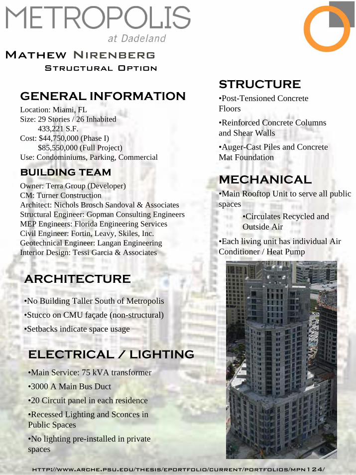
Mathew NirenbergStructural Option
GENERAL INFORMATIONLocation: Miami, FLSize: 29 Stories / 26 Inhabited
433,221 S.F.Cost: $44,750,000 (Phase I)
$85,550,000 (Full Project)Use: Condominiums, Parking, Commercial
Owner: Terra Group (Developer)CM: Turner ConstructionArchitect: Nichols Brosch Sandoval & AssociatesStructural Engineer: Gopman Consulting EngineersMEP Engineers: Florida Engineering ServicesCivil Engineer: Fortin, Leavy, Skiles, Inc.Geotechnical Engineer: Langan EngineeringInterior Design: Tessi Garcia & Associates
ARCHITECTURE
•No Building Taller South of Metropolis•Stucco on CMU façade (non-structural)•Setbacks indicate space usage
STRUCTURE•Post-Tensioned Concrete Floors•Reinforced Concrete Columns and Shear Walls•Auger-Cast Piles and Concrete Mat Foundation
MECHANICAL•Main Rooftop Unit to serve all public spaces
•Circulates Recycled and Outside Air
•Each living unit has individual Air Conditioner / Heat Pump
ELECTRICAL / LIGHTING•Main Service: 75 kVA transformer•3000 A Main Bus Duct•20 Circuit panel in each residence•Recessed Lighting and Sconces in Public Spaces•No lighting pre-installed in private spaces
building team
http://www.arche.psu.edu/thesis/eportfolio/current/portfolios/mpn124/

Final Thesis Design Report – Executive Summary
Over the course of the past academic year I have been analyzing the Metropolis at
Dadeland, Phase I with a focus on the structural system. After an extensive investigation
of the structure of the existing building and brief analysis of the construction climate in
Miami, Florida I am proposing an alternate system for the building. Since all of the
construction of large buildings currently underway in the greater Miami area is concrete
with post-tensioned slabs, I chose to analyze whether or not a steel frame work in the
given situation.
One thing that I tried to maintain was the existing floor plans as much as possible.
This was only a minor challenge when setting up the gravity members of the building.
However, this did create a severe lack of ability to locate braced frames in my proposed
structure which ended up being its ultimate demise. The moment frames that I was
forced to use a lot of were not able to sufficiently carry the lateral load from the 150mph
wind that was impacting the building.
I also investigated the electrical system in a typical condominium unit and
estimated the difference in cost between the two structural systems. The electrical system
was impacted because I chose to add recessed lighting into the dropped ceilings that I
introduced to the building due to the steel frame. The result was that I used two more
circuits than the existing unit, but the feeder and main breaker were unaffected.
In the estimates the concrete structure ended up being noticeably cheaper than the
steel and that is independent of the cost for the new circuit breakers and light fixtures that
I have proposed to introduce to the space or the possible savings from reduction in
foundation, which could alter the price in either direction depending on exact concrete
savings or quality of the lighting fixtures used.
Overall, if the floor plans had been arranged to accommodate the grid of the steel
frame, the steel could have worked as a structural system. But as is, there is not enough
lateral stiffness to resist the loads. The concrete is also a cheaper system which makes
the developer and future tenants happier. In conclusion, there is a reason that all of the
current large construction projects in South Florida are concrete even if steel could work
given favorable circumstances.
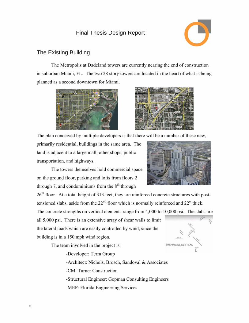
Final Thesis Design Report The Existing Building The Metropolis at Dadeland towers are currently nearing the end of construction
in suburban Miami, FL. The two 28 story towers are located in the heart of what is being
planned as a second downtown for Miami.
The plan conceived by multiple developers is that there will be a number of these new,
primarily residential, buildings in the same area. The
land is adjacent to a large mall, other shops, public
transportation, and highways.
The towers themselves hold commercial space
on the ground floor, parking and lofts from floors 2
through 7, and condominiums from the 8th through
26th floor. At a total height of 313 feet, they are reinforced concrete structures with post-
tensioned slabs, aside from the 22nd floor which is normally reinforced and 22” thick.
The concrete strengths on vertical elements range from 4,000 to 10,000 psi. The slabs are
all 5,000 psi. There is an extensive array of shear walls to limit
the lateral loads which are easily controlled by wind, since the
building is in a 150 mph wind region.
The team involved in the project is:
-Developer: Terra Group
-Architect: Nichols, Brosch, Sandoval & Associates
-CM: Turner Construction
-Structural Engineer: Gopman Consulting Engineers
-MEP: Florida Engineering Services

-Civil Engineer: Fortin, Leavy, Skiles, Inc.
-Interior Design: Tessi Garcia & Associates
There are a variety of unique aspects about this building
other than the structure. Because there are two towers being built as
separate phases there were a number of challenges. In the beginning
of the process site trailers were located on the ground that was going
to be occupied by phase II. Once phase II was began construction
those offices were moved into temporary rooms in the parking deck
of phase I until very late in the project. The load of having a pool between the two
towers also resulted in the second tower needing to reach the eighth level before the pool
joining the two towers could be erected.
There was also the challenge of providing personal air handling units for the
individual spaces in conjunction with a centralized air handling system for all of the
public and retail spaces throughout the building. This included using special sensors and
fans in the parking deck to minimize issues with carbon monoxide.
For circulation through the building there are 5 elevators and 3 stairwells so that
the parking deck and residences can be accessed separately and efficiently. The
architecture, which I plan to keep in tact as much as possible, is most noticed for its
irregular floor plans, particularly at the lower levels, and the off-white stucco finish
covering the surface of the entire non-glazed façade.

Proposal for Thesis Investigation In order to investigate other building structural system for the Metropolis at
Dadeland I need to begin with creating a grid onto which a structural system can be
applied. The only system that can be used effectively without any reasonable grid is a
post-tensioned slab, which I am investigating a replacement of. This grid, along with the
rest of my design, should not noticeably alter the current layout of the building.
Once the grid has been established I will begin by investigating a steel framed
structure. The frame will be responsible for resisting all loads, meaning no shear walls
will be used. This is because the existing shear walls, which run in a variety of directions
and angles, would not reasonably agree with a uniform, rectilinear grid. To resist the
lateral loads I will attempt to utilize braced frames wherever they can be concealed within
walls. Otherwise, I will begin applying moment frames until sufficient lateral stiffness
has been achieved.
In the existing version of the building most of the living spaces utilize the bottom
of the slab above, with a plastered finish, as the ceiling. Because of this, there are no
recessed lights in the main living spaces. Since the steel frame inherently utilizes a
suspended ceiling, I can now easily incorporate recessed lights throughout the living
spaces as there is a ceiling plenum to recess into. Because of this new flexibility my first
breadth investigation will be to analyze how the addition of ceiling recessed lights will
affect the electrical wiring of the individual residential spaces.
My second breadth investigation will be to look at the economic feasibility of my
system. This will include a look at the cost for my proposed system and the system that
has already been implemented in the building. Since there are positive and negative
aspects to both steel and concrete construction I want to see how greatly cost differences
could lead to a decision to use one material over the other for the given situation.
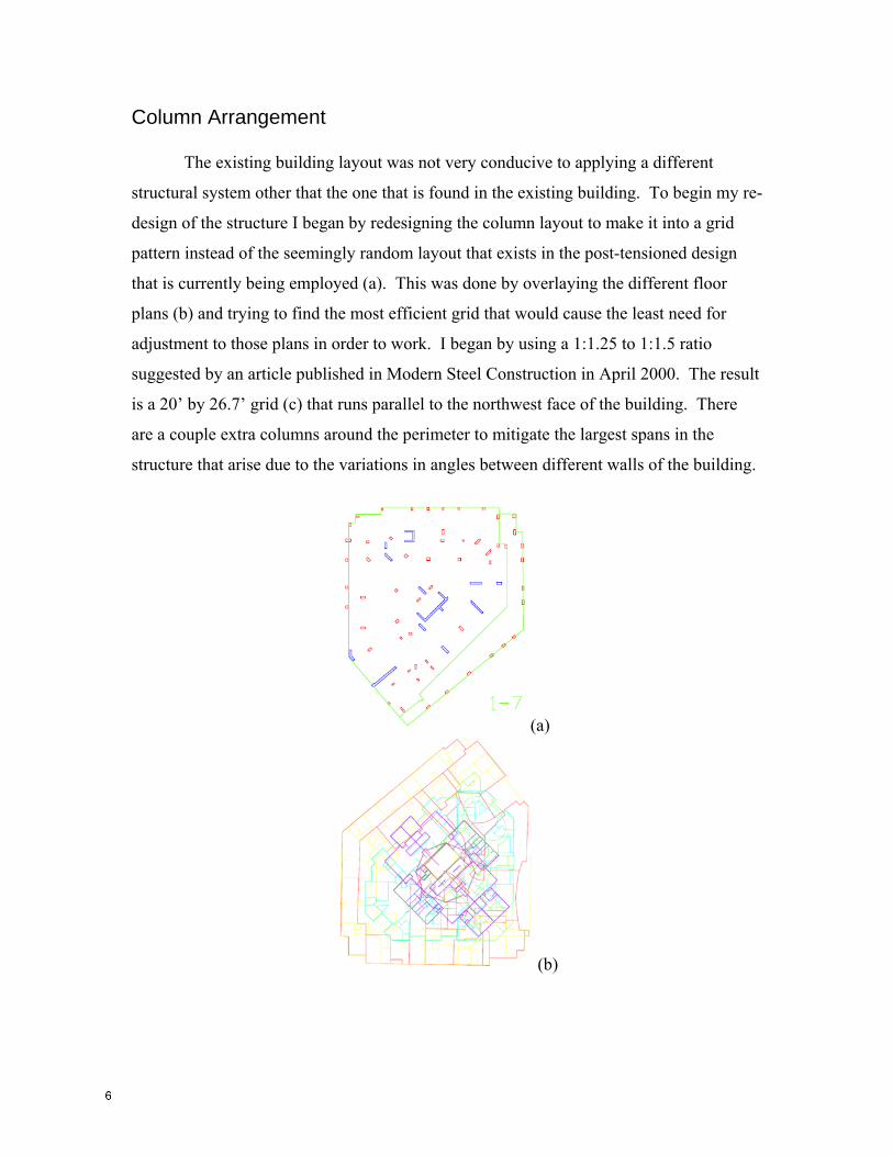
Column Arrangement The existing building layout was not very conducive to applying a different
structural system other that the one that is found in the existing building. To begin my re-
design of the structure I began by redesigning the column layout to make it into a grid
pattern instead of the seemingly random layout that exists in the post-tensioned design
that is currently being employed (a). This was done by overlaying the different floor
plans (b) and trying to find the most efficient grid that would cause the least need for
adjustment to those plans in order to work. I began by using a 1:1.25 to 1:1.5 ratio
suggested by an article published in Modern Steel Construction in April 2000. The result
is a 20’ by 26.7’ grid (c) that runs parallel to the northwest face of the building. There
are a couple extra columns around the perimeter to mitigate the largest spans in the
structure that arise due to the variations in angles between different walls of the building.
(a)
(b)
(c)
Loading When trying to size members it has been easiest to start with sizing members for
gravity loads. To make the playing field fair for comparison between my proposed
structure and the existing building I used the same loads that they referenced instead of
trying to select my case specific loads that could be found in ASCE 7-02. I did, however,
use the ASCE 7-02 load combinations from section 2.3.
For the majority of the structure the superimposed loads are assumed to be Dead: Units: 20psf CMU: 65 psf
Live: Units: 40 psf Balconies: 60 psf Public Space: 100 psf
Average ≈ 55 psf Roof: 15 psf
The exception is the eighth floor which has much greater loads due to the presence of the
fitness areas. Inside the superimposed dead load is 85 psf and live load is 100 psf.
Outdoors the superimposed dead load is 95 psf and the live load is 256 psf.
For initial sizing an estimated self weight of 65 psf was used.
Initial Floor Member Sizing
For the standard beam non-composite design would call for a W10x26. Based on
the composite design tables a W10x12 would be sufficient. This would only require 4
shear studs, which still maintains a savings of 322 pounds of steel on every beam. For a standard girder non-composite design calls for a W12x58. Alternatively
composite design only requires a W10x26. This would require 26 shear studs per girder
which still leads to a theoretical savings of 460 pounds of steel for each girder plus a
savings of 2” of depth.
For the floor form deck will be used to support the concrete. From the United
Steel Deck, Inc. catalog, UF1X 26-gage deck with 3” of cover will be sufficient for
strength, serviceability, and fire protection. This will cause the assumed load to change
since this assembly weighs 30 psf.
The eighth floor, the one with different loading conditions, will have noticeably
larger members. The part of the floor that is on the interior of the building will require
beams that are W10x17 and girders that are W14x38. Outside the footprint of these walls
the beams need to be W10x26 and the girders need to be W18x60. All of these beams
will be in composite action with the floor slab which will be a 3.5” slab placed on the
same form deck as the rest of the building.
While some of the other members could be smaller due to shorter spans from
unique geometry, not enough would be gained by having such a variety of sizes. The
resulting complexity of fabrication and construction would not be worth saved weight in
the structure.
After adjusting the loads for the new slab weight the difference was not
substantial enough to cause a reason to resize any of the previously determined members.
All of these actual calculations can be found in appendix B.
Initial Column Sizing
The columns were originally sized for gravity loads only. This means that the
values were based on a combination of 1.2DL + 1.6LL. Most of the columns in the
structure can take advantage of full allowable live load reduction (0.4). Only the top
couple of floors do not have enough tributary area to allow for such large reductions.
There are also limitations in reduction in the parking deck areas as is stated in ASCE 7-02
- 4.8.3. Beams can have no reduction and columns are limited to 0.2.
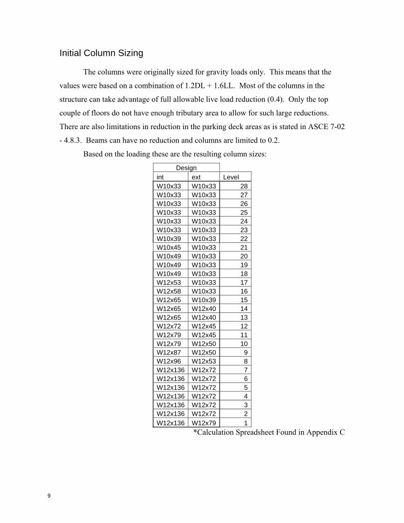
Based on the loading these are the resulting column sizes:
Design int ext Level W10x33 W10x33 28W10x33 W10x33 27W10x33 W10x33 26W10x33 W10x33 25W10x33 W10x33 24W10x33 W10x33 23W10x39 W10x33 22W10x45 W10x33 21W10x49 W10x33 20W10x49 W10x33 19W10x49 W10x33 18W12x53 W10x33 17W12x58 W10x33 16W12x65 W10x39 15W12x65 W12x40 14W12x65 W12x40 13W12x72 W12x45 12W12x79 W12x45 11W12x79 W12x50 10W12x87 W12x50 9W12x96 W12x53 8W12x136 W12x72 7W12x136 W12x72 6W12x136 W12x72 5W12x136 W12x72 4W12x136 W12x72 3W12x136 W12x72 2W12x136 W12x79 1
*Calculation Spreadsheet Found in Appendix C

RAM Structural Model In order to analyze the existing concrete structure I modeled it in ETABS. For
analysis of the interaction between structural members I assembled my final model
utilizing RAM Structural System. I was planning on using ETABS for the steel model as
well in order to keep the comparison between my structural system and that of the
existing structure as fair as possible. However, ETABS did not easily allow for regular
adjustments to geometry that I needed to implement, and RAM has been presented as the
industry standard for steel modeling and design.
A major concern when laying out the framing, aside from locating to columns to
minimize necessary changes to the floor plan, has been to keep the top of the building
under the height limitation. This has been a concern since a steel frame is inherently
taller than post-tensioned concrete. In order to allow this to happen a couple of the
higher floor-to-ceiling heights had to be slightly reduced. For instance the 18’ ground
floor is now only 16’. This offset the increase of some of the residential floors. Also to
minimize this issue I brought the floor-to-ceiling heights in the condos down from almost
9’ to 8’, which is still a reasonable ceiling height for a residence.

The lateral loading I applied to the model is based on ASCE 7-02 chapters 6 and 8
and can be seen in appendix D. In building the model I began with as few lateral
resisting elements as possible. I tried to implement as many braced frames into the floor
plan as possible without any noticeable changes to the floor plan as I originally proposed.
This meant that the number of frames I was able to use was severely insufficient to resist
the lateral loads applied by the 150mph wind loads. At that point I began adding moment
frames progressively until they engulfed the nearly entire grid of the structure.
The red members shown above in the figure represent the lateral resisting elements. As
that was not enough resistance, the sizes were increased until a point was reached that
some of the sizes were beginning to be unreasonable, especially in relation to the
mitigation of deflection that resulted from the changes. The best that I could achieve was
a lateral deflection at the top of the building of 47.8” (appendix E), which is roughly a
ratio of H/80. This is nowhere near acceptable. However, if this building were relocated
to most locations in the United States, where the mean wind speed is 90mph, the lateral
deflection is a very reasonable 16” in the critical direction. There are still some floors
that are slightly over allowable drift, but they are close enough to be remedied with some
minimal resizing. This would especially be true if more efficient braces other than the
cross bracing I used were utilized such as chevron bracing, as has been suggested in past
AE thesis reports.
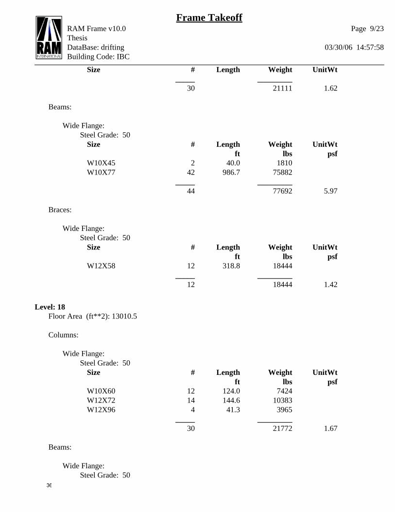
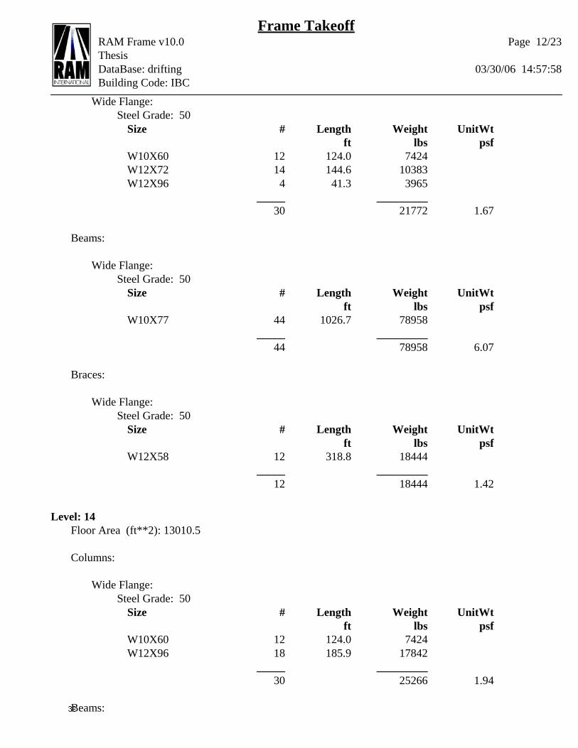
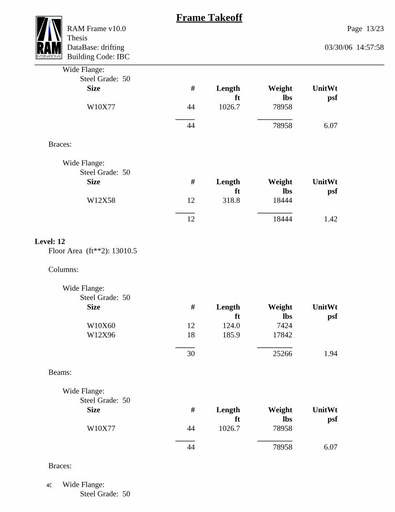
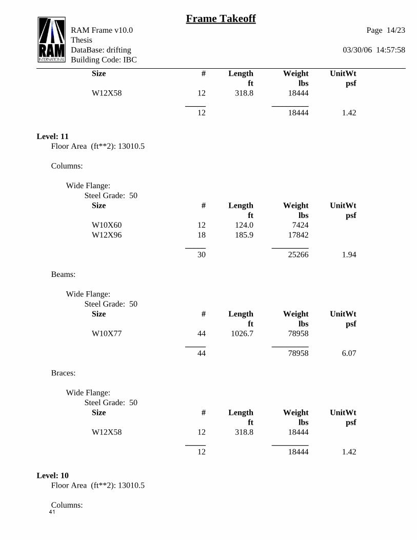
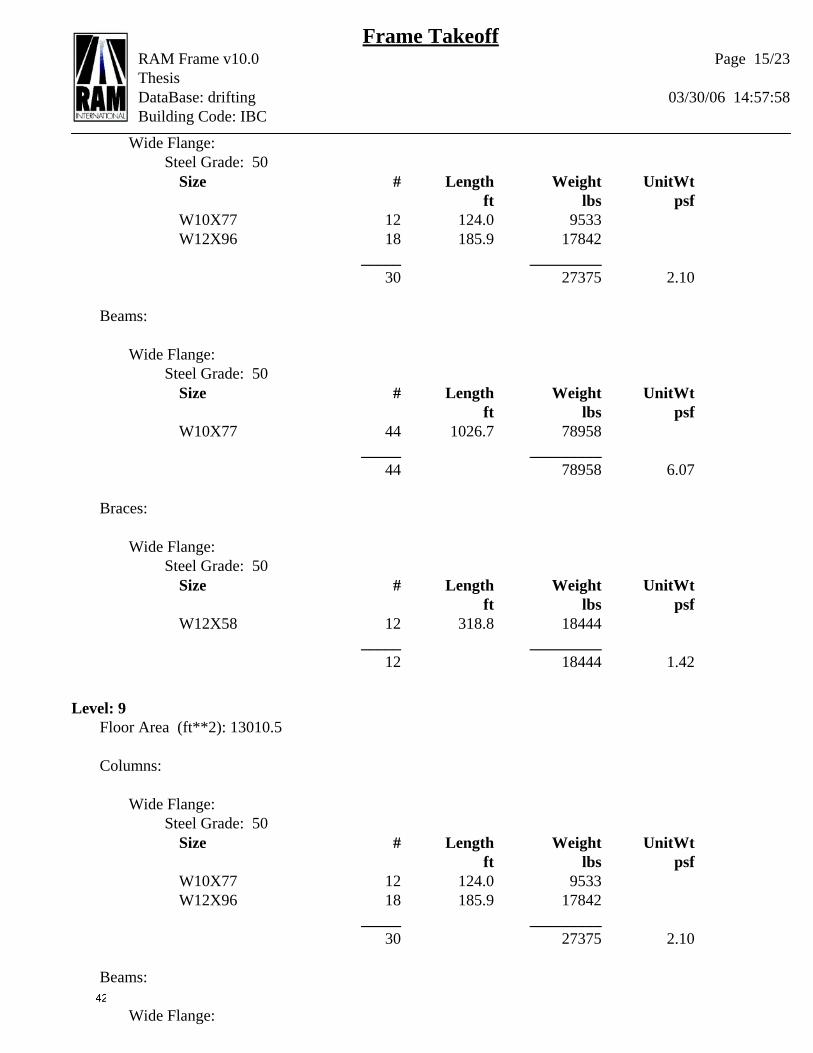
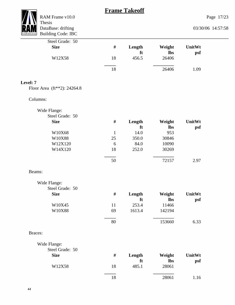
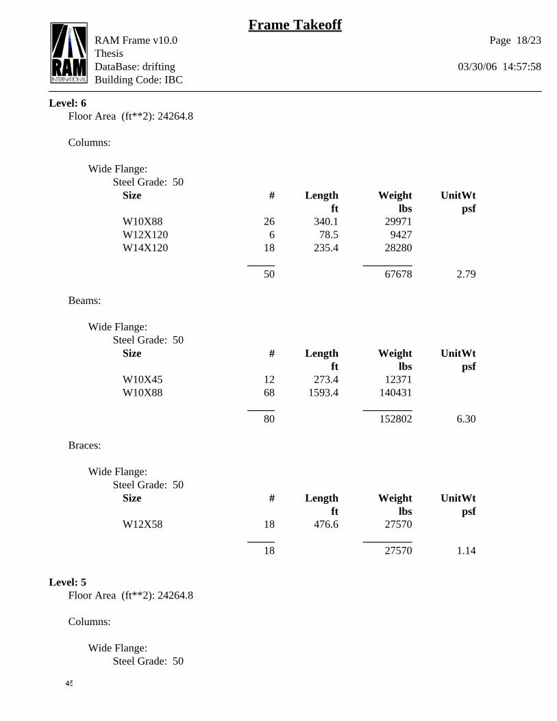
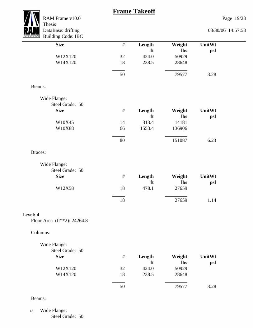
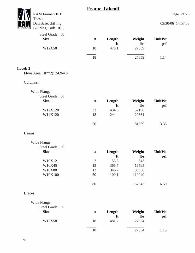
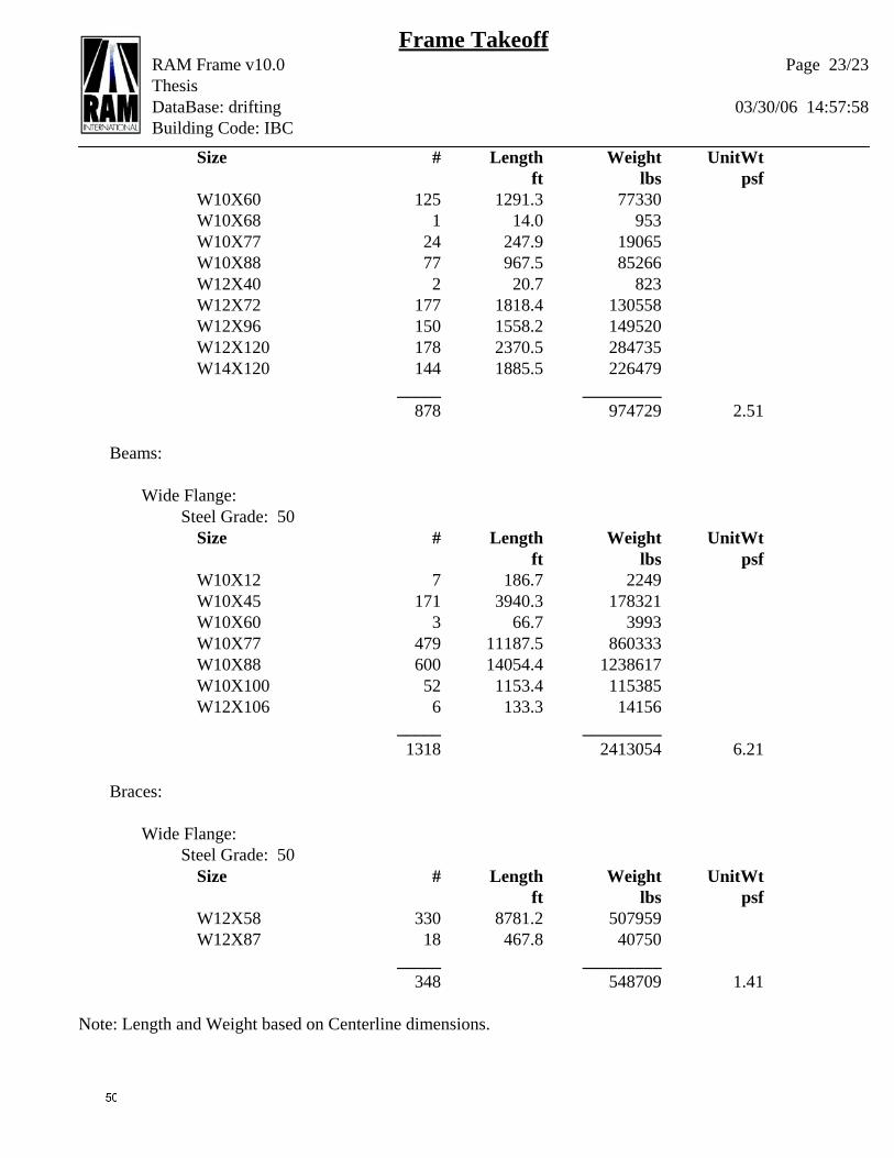
Resulting Design A detailed member takeoff can be found in appendix F.
Beams
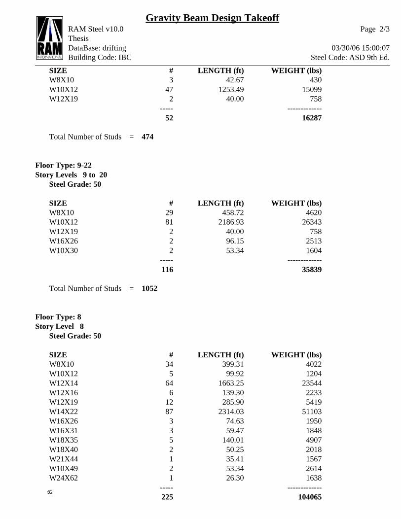
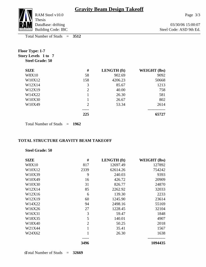
I have maintained the 3” of cover over 1” form deck and ¾” shear studs for
composite action from the preliminary designs.
Most of the beams that directly connect columns have been altered to
accommodate for their inclusion in moment frames. The intermediate beams on all levels
are primarily W10x12’s with the exception of the eighth floor which consists mostly of
W12x14’s. The girders on the eighth floor are also larger, up to W24x62, due to the
increased loads on that level. There are also some w8x10’s in the structure for the
intermediate beams that are cut off by the angles of the building’s exterior.
There are a variety of other sizes in the building (W10x30, W10x39, W10x49,
W12x19, W14x22, W16x31, W21x24, and W18x35) which either account for resisting
lateral loads or the irregularly long beams along the angled perimeter of the structure.
Columns There are only 9 columns, each 8 stories tall, that due not carry lateral load. They
are only needed to be W10x33’s. The rest of the columns within the structure have been
noticeably increased over their required sizes for gravity loads to account for the forces of
wind on the structure. That has resulted in the use of columns ranging in size from
W10x60 to W14x120. The larger sizes are much more predominant in the building.
Braces In an attempt to add the most possible rigidity to the available braced frames I
opted to use W shapes to allow for easier access of A992 material. I limited the size of
these braces to be no larger that the columns which they would be connecting to and
control wall thicknesses. This yielded the use of W12x58’s for all of the braces.
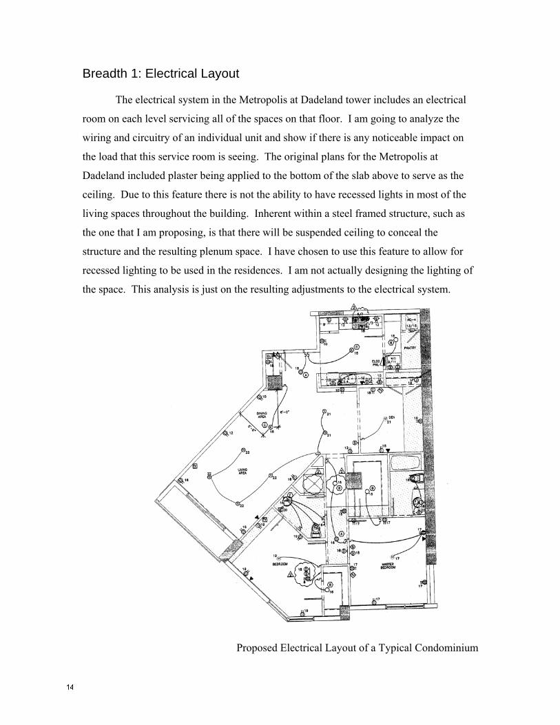
Breadth 1: Electrical Layout The electrical system in the Metropolis at Dadeland tower includes an electrical
room on each level servicing all of the spaces on that floor. I am going to analyze the
wiring and circuitry of an individual unit and show if there is any noticeable impact on
the load that this service room is seeing. The original plans for the Metropolis at
Dadeland included plaster being applied to the bottom of the slab above to serve as the
ceiling. Due to this feature there is not the ability to have recessed lights in most of the
living spaces throughout the building. Inherent within a steel framed structure, such as
the one that I am proposing, is that there will be suspended ceiling to conceal the
structure and the resulting plenum space. I have chosen to use this feature to allow for
recessed lighting to be used in the residences. I am not actually designing the lighting of
the space. This analysis is just on the resulting adjustments to the electrical system.
Proposed Electrical Layout of a Typical Condominium
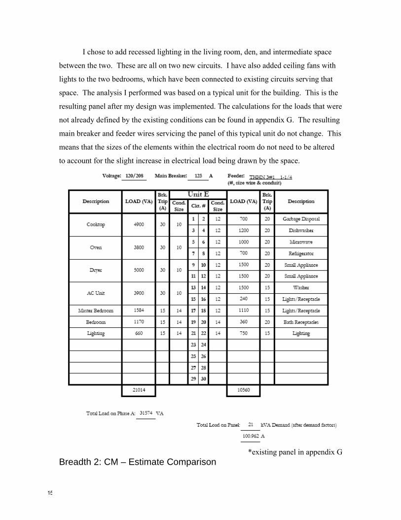
I chose to add recessed lighting in the living room, den, and intermediate space
between the two. These are all on two new circuits. I have also added ceiling fans with
lights to the two bedrooms, which have been connected to existing circuits serving that
space. The analysis I performed was based on a typical unit for the building. This is the
resulting panel after my design was implemented. The calculations for the loads that were
not already defined by the existing conditions can be found in appendix G. The resulting
main breaker and feeder wires servicing the panel of this typical unit do not change. This
means that the sizes of the elements within the electrical room do not need to be altered
to account for the slight increase in electrical load being drawn by the space.
*existing panel in appendix G
Breadth 2: CM – Estimate Comparison
An all important part of choosing a system to implement into a building is the cost
of the system relative to its alternatives. When comparing a steel frame to post-tensioned
concrete a major consideration is market price for the materials and the local labor force.
With this there are a lot of intangibles that can change every month. I will be focusing
my estimation on standard numbers from ICE 2000 Estimating. The estimate for the
steel building has an inflated number of braced frames in order to mimic a structure that
should work for the given loading. Based on this program the steel structure will cost
approximately $3.6 million and the concrete structure should cost $9.1 million. The
details resulting in these values can be seen in appendix H. This seems like a clear
advantage to steel independent of the other variables involved. However, there is a need
for fire proofing on the steel which instantly raises its price to $15.5 million. Instantly,
concrete seems to be the favorable system based solely on price.
This does not account for the added costs of the circuits and light fixtures that I
have proposed to install in conjunction with the steel system. This can be made up for
because the foundation can be greatly reduced because of weight of the steel structure
versus the existing concrete. The elimination of the mat slab could save nearly $700,000.
Depending on the quality of the lighting components to be included would determine
exactly which system this comparison favors, but should not greatly effect the overall
comparison between the two systems.
Conclusion:

There is much more to selecting a system than just price and drift values. The
biggest reason that I had trouble eliminating such outrageous drift from my building was
the fact that there were not enough places to implement braced frames without running
through the middle of spaces. Had the architect had a grid system in mind with the need
to walls to be located in certain places a more suitable floor plan could have been
designed to allow for the steel frame to be effective.
When comparing the suitability of the systems from an economic standpoint the
concrete structure also shows advantages. However, one thing to keep in mind is that the
foundation could be made significantly smaller for the steel framework than the 5 foot
thick mat with an array of auger-cast piles that is in place to support the concrete
structure. Another thing that is hard to take into account is the local building climate. At
the time that this building began design and construction every tall building in Miami was
being built with concrete and post-tensioned slabs. It has gotten to the point that the post-
tensioning contractors are so busy that is can be challenging to get them to add your
building to the list. In a conversation with principals at Bliss & Nyitray, Inc. in Miami,
they mentioned that they had just proposed a building out of concrete for this reason
among others. There is also the added bonus of the shorter construction time inherent in
a steel frame as long as the possible months of lead time necessary can be acceptable.
I also am a fan of having recessed lighting strategically located throughout my
living space, which is much easier to implement with a suspended ceiling inherent in a
steel structure.
In conclusion, for the building as is, without any major adjustments to the floor
plans, there is no building system better than the concrete structure with a post-tensioned
slab. The steel frame that I tried to use just does not work. If the building were
rearranged, possibly beginning with the footprint, but more importantly the locations of
internal walls in the floor plans a steel frame could work and has some distinct
advantages. Shorter construction time and some conveniences available to other
building disciplines would help. And while the steel structure is more expensive than
concrete, the time saved in construction, meaning tenants could move in sooner, may be
worth the offset in cost presuming that the structure actually works.
Acknowledgments: I would like to thank the entire field office of Tuner Construction, Gary Ferguson
of Terra Group, and Eugene Crosby from Gopman Consulting Engineers for providing
me with the necessary information, materials, and site access to be prepared to undertake
this project. I also appreciate the help that was provided for me by Dr. Walt Schneider
and the rest of the AE faculty. Also worthy of praise are the variety other students who
were there in the thesis studio to answer random question as they arose.
References: Conversations with: Hope Furrer of Hope Furrer Associates Paul Zilio and Bart Wallis of Bliss & Nyitray, Inc
Value Engineering for Steel Construction. Modern Steel Construction, April 2000. ASCE 7-02 For Lateral Loading Existing building plans For Gravity Loads and Zoning Requirements
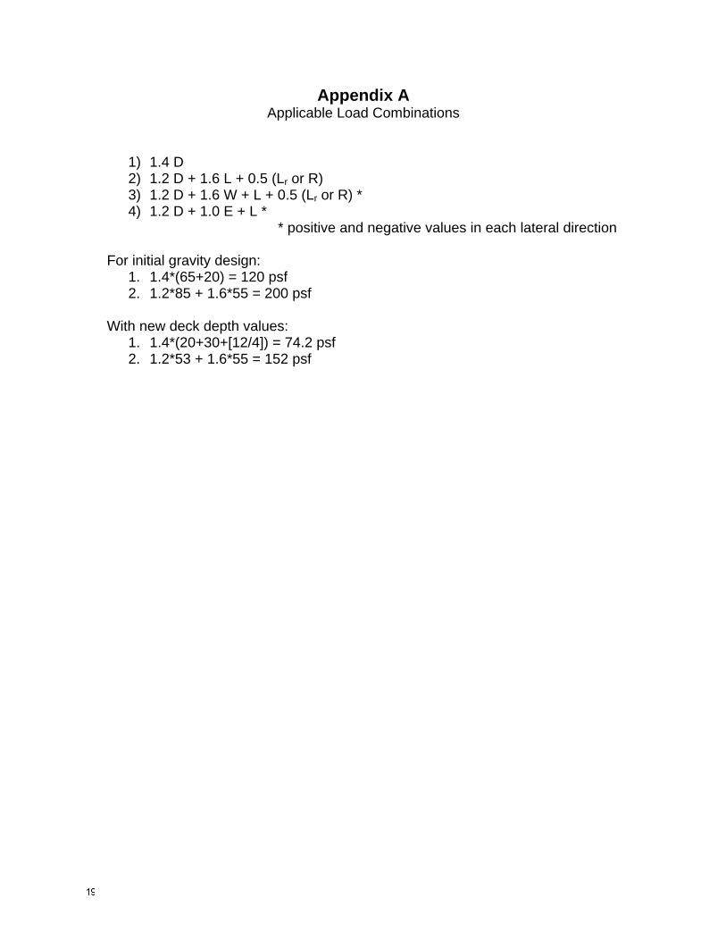
Appendix A Applicable Load Combinations
1) 1.4 D 2) 1.2 D + 1.6 L + 0.5 (Lr or R) 3) 1.2 D + 1.6 W + L + 0.5 (Lr or R) * 4) 1.2 D + 1.0 E + L *
* positive and negative values in each lateral direction For initial gravity design:
1. 1.4*(65+20) = 120 psf 2. 1.2*85 + 1.6*55 = 200 psf
With new deck depth values:
1. 1.4*(20+30+[12/4]) = 74.2 psf 2. 1.2*53 + 1.6*55 = 152 psf

Appendix B Initial Floor Member Sizing
Decking

Appendix C Column Sizing
Interior Exterior Design
Level area (ft^2)
load (k) reduction
new load (k)
area (ft^2)
load (k) reduction
new load (k)
Floor Height
(ft) int ext 28 500 76 0.59 31.5 250 38 0.72 10.5 15 W10x33 W10x3327 500 152 0.49 78.0 250 76 0.59 31.5 9.5 W10x33 W10x3326 500 228 0.44 126.8 250 114 0.52 54.3 8.67 W10x33 W10x3325 500 304 0.42 177.0 250 152 0.49 78.0 11.67 W10x33 W10x3324 500 380 0.4 228.0 250 190 0.46 102.2 10.67 W10x33 W10x3323 500 456 0.4 273.6 250 228 0.44 126.8 10.67 W10x33 W10x3322 500 532 0.4 319.2 250 266 0.43 151.8 10.67 W10x39 W10x3321 500 608 0.4 364.8 250 304 0.42 177.0 11.67 W10x45 W10x3320 500 684 0.4 410.4 250 342 0.41 202.4 11.67 W10x49 W10x3319 500 760 0.4 456.0 250 380 0.4 228.0 9.33 W10x49 W10x3318 500 836 0.4 501.6 250 418 0.4 250.8 9.33 W10x49 W10x3317 500 912 0.4 547.2 250 456 0.4 273.6 9.33 W12x53 W10x3316 500 988 0.4 592.8 250 494 0.4 296.4 9.33 W12x58 W10x3315 500 1064 0.4 638.4 250 532 0.4 319.2 9.33 W12x65 W10x3914 500 1140 0.4 684.0 250 570 0.4 342.0 9.33 W12x65 W12x4013 500 1216 0.4 729.6 250 608 0.4 364.8 9.33 W12x65 W12x4012 500 1292 0.4 775.2 250 646 0.4 387.6 9.33 W12x72 W12x4511 500 1368 0.4 820.8 250 684 0.4 410.4 9.33 W12x79 W12x4510 500 1444 0.4 866.4 250 722 0.4 433.2 9.33 W12x79 W12x50
9 500 1520 0.4 912.0 250 760 0.4 456.0 9.33 W12x87 W12x508 500 1596 0.4 957.6 250 798 0.4 478.8 10.67 W12x96 W12x537 500 1746 0 1107.6 250 938 0 618.8 18 W12x136 W12x726 500 1822 0.2 1122.8 250 976 0.2 626.4 13 W12x136 W12x725 500 1898 0.2 1138.0 250 1014 0.2 634.0 13.25 W12x136 W12x724 500 1974 0.2 1153.2 250 1052 0.2 641.6 13.25 W12x136 W12x723 500 2050 0.2 1168.4 250 1090 0.2 649.2 13.25 W12x136 W12x722 500 2126 0.2 1183.6 250 1128 0.2 656.8 13.5 W12x136 W12x721 500 2202 0.4 1214.0 250 1166 0.4 672.0 15.67 W12x136 W12x79
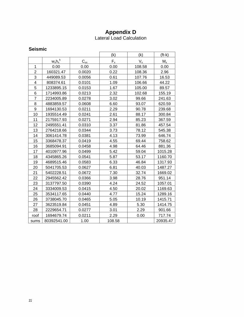
Appendix D Lateral Load Calculation
Seismic
(k) (k) (ft-k) wxhx
k Cvx Fx Vx Mx 1 0.00 0.00 0.00 108.58 0.00 2 160321.47 0.0020 0.22 108.36 2.96 3 449089.53 0.0056 0.61 107.76 16.53 4 808374.61 0.0101 1.09 106.66 44.22 5 1233895.15 0.0153 1.67 105.00 89.57 6 1714993.86 0.0213 2.32 102.68 155.19 7 2234005.89 0.0278 3.02 99.66 241.63 8 4883859.57 0.0608 6.60 93.07 620.59 9 1694130.53 0.0211 2.29 90.78 239.68 10 1935514.49 0.0241 2.61 88.17 300.84 11 2175917.93 0.0271 2.94 85.23 367.59 12 2495551.41 0.0310 3.37 81.86 457.54 13 2764218.66 0.0344 3.73 78.12 545.38 14 3061414.78 0.0381 4.13 73.99 646.74 15 3368478.37 0.0419 4.55 69.44 758.62 16 3685094.91 0.0458 4.98 64.46 881.36 17 4010977.96 0.0499 5.42 59.04 1015.28 18 4345865.26 0.0541 5.87 53.17 1160.70 19 4689515.46 0.0583 6.33 46.84 1317.93 20 5041705.53 0.0627 6.81 40.03 1487.27 21 5402228.51 0.0672 7.30 32.74 1669.02 22 2945562.42 0.0366 3.98 28.76 951.14 23 3137797.50 0.0390 4.24 24.52 1057.01 24 3334009.53 0.0415 4.50 20.02 1169.63 25 3534117.65 0.0440 4.77 15.24 1289.16 26 3738045.70 0.0465 5.05 10.19 1415.71 27 3623519.84 0.0451 4.89 5.30 1414.75 28 2229654.71 0.0277 3.01 2.29 901.66
roof 1694679.74 0.0211 2.29 0.00 717.74 sums 80392541.00 1.00 108.58 20935.47

Wind (controls) floor
# height
(in) height kh kz alpha zg qz qh F (klf) (E-W) F (klf)(N-S) 1 0 0.00 0.85 0.85 9.5 900 41.56 78.82 0.00 0.00 2 164 13.67 0.90 0.85 9.5 900 41.56 78.82 0.63 0.64 3 327 27.25 0.98 0.96 9.5 900 47.13 78.82 0.69 0.69 4 486 40.50 1.05 1.05 9.5 900 51.23 78.82 0.72 0.72 5 645 53.75 1.11 1.11 9.5 900 54.37 78.82 0.76 0.76 6 804 67.00 1.16 1.16 9.5 900 56.95 78.82 0.78 0.79 7 961 80.08 1.22 1.21 9.5 900 59.13 78.82 0.80 0.80 8 1129 94.08 1.26 1.25 9.5 900 61.17 78.82 0.88 0.88 9 1257 104.75 1.28 1.28 9.5 900 62.57 78.82 0.68 0.68
10 1381 115.08 1.31 1.30 9.5 900 63.82 78.82 0.67 0.67 11 1505 125.42 1.33 1.33 9.5 900 64.99 78.82 0.68 0.68 12 1629 135.75 1.35 1.35 9.5 900 66.08 78.82 0.69 0.69 14 1753 146.08 1.37 1.37 9.5 900 67.11 78.82 0.70 0.70 15 1877 156.42 1.38 1.39 9.5 900 68.08 78.82 0.71 0.71 16 2001 166.75 1.40 1.41 9.5 900 69.01 78.82 0.72 0.72 17 2125 177.08 1.42 1.43 9.5 900 69.89 78.82 0.72 0.72 18 2249 187.42 1.44 1.44 9.5 900 70.73 78.82 0.73 0.73 19 2373 197.75 1.45 1.46 9.5 900 71.53 78.82 0.74 0.74 20 2497 208.08 1.46 1.48 9.5 900 72.30 78.82 0.74 0.75 21 2621 218.42 1.48 1.49 9.5 900 73.04 78.82 0.75 0.75 22 2745 228.75 1.49 1.51 9.5 900 73.76 78.82 0.76 0.76 23 2869 239.08 1.51 1.52 9.5 900 74.45 78.82 0.76 0.76 24 2993 249.42 1.53 1.53 9.5 900 75.11 78.82 0.77 0.77 25 3117 259.75 1.53 1.55 9.5 900 75.76 78.82 0.77 0.78 26 3241 270.08 1.55 1.56 9.5 900 76.38 78.82 0.78 0.78 27 3365 280.42 1.56 1.57 9.5 900 76.99 78.82 0.78 0.79 28 3469 289.08 1.58 1.58 9.5 900 77.48 78.82 0.66 0.66 29 3593 299.42 1.59 1.59 9.5 900 78.06 78.82 0.79 0.79 30 3763 313.58 1.60 1.61 9.5 900 78.82 78.82 0.55 0.55

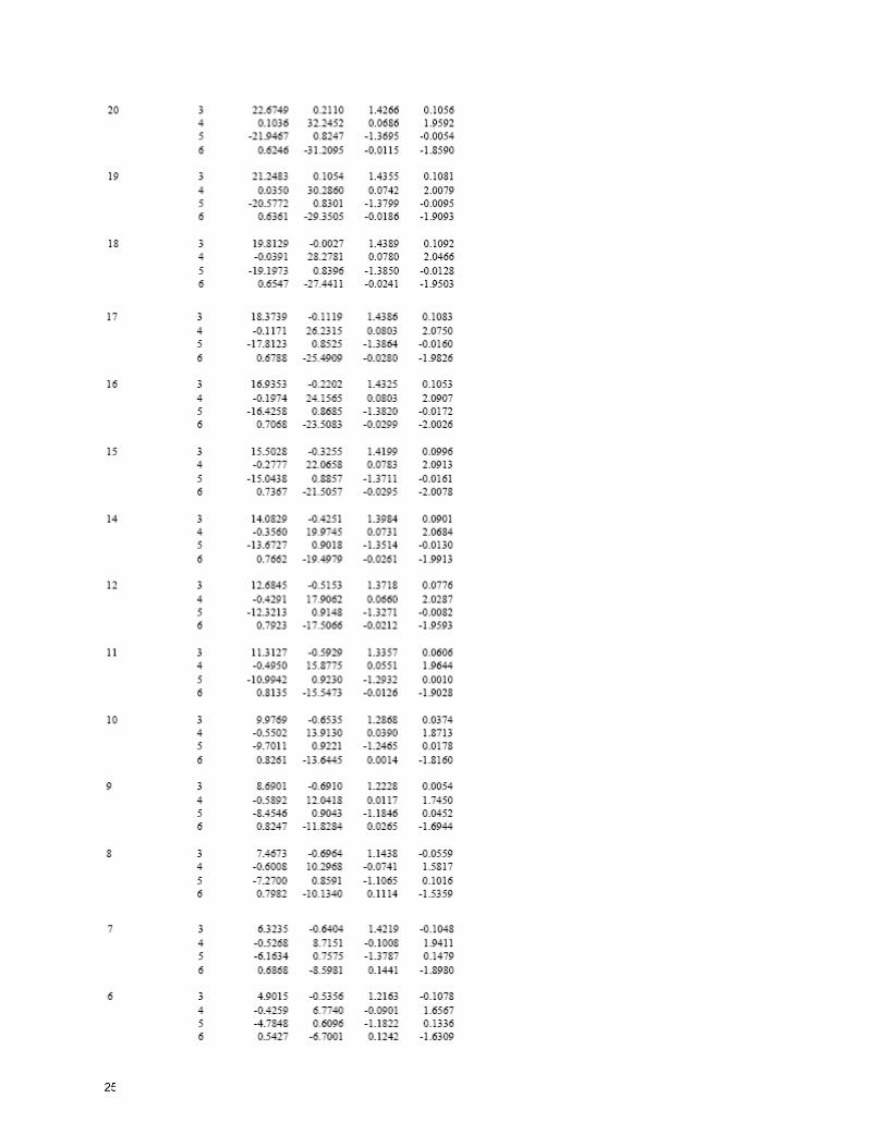
Appendix E Lateral Displacement / Drift
Critical Load Combinations
Lateral Displacement / Story Drift

Sample of Top Floor at 90mph

Appendix F Member Sizes
Lateral
Gravity Beams
Gravity Columns
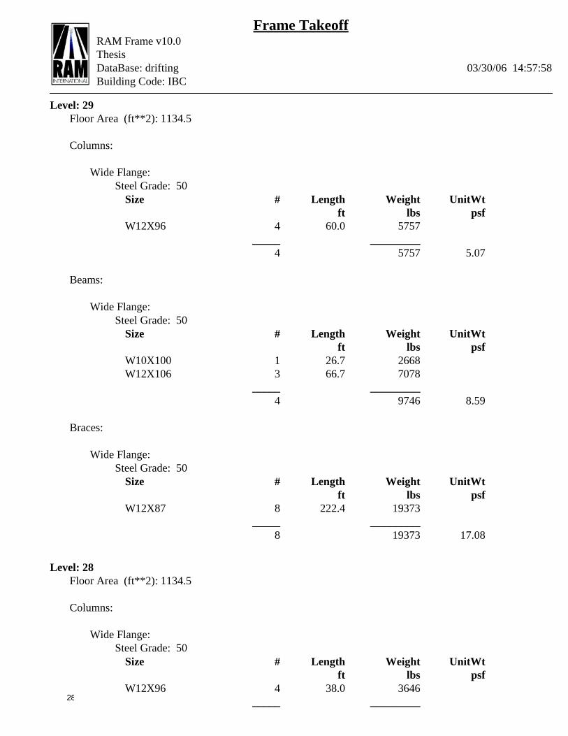
Frame TakeoffRAM Frame v10.0ThesisDataBase: drifting 03/30/06 14:57:58Building Code: IBC
Level: 29Floor Area (ft**2): 1134.5
Columns:
Wide Flange:Steel Grade: 50
Size # Length Weight UnitWt ft lbs psf
W12X96 4 60.0 5757 _____ _________
4 5757 5.07
Beams:
Wide Flange:Steel Grade: 50
Size # Length Weight UnitWt ft lbs psf
W10X100 1 26.7 2668W12X106 3 66.7 7078
_____ _________4 9746 8.59
Braces:
Wide Flange:Steel Grade: 50
Size # Length Weight UnitWt ft lbs psf
W12X87 8 222.4 19373 _____ _________
8 19373 17.08
Level: 28Floor Area (ft**2): 1134.5
Columns:
Wide Flange:Steel Grade: 50
Size # Length Weight UnitWt ft lbs psf
W12X96 4 38.0 3646 _____ _________
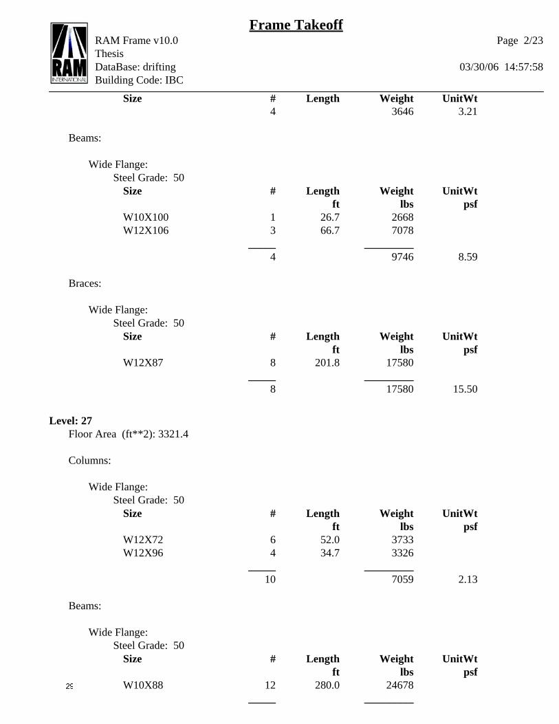
Frame TakeoffRAM Frame v10.0ThesisDataBase: drifting 03/30/06 14:57:58Building Code: IBC
Size # Length Weight UnitWt4 3646 3.21
Beams:
Wide Flange:Steel Grade: 50
Size # Length Weight UnitWt ft lbs psf
W10X100 1 26.7 2668W12X106 3 66.7 7078
_____ _________4 9746 8.59
Braces:
Wide Flange:Steel Grade: 50
Size # Length Weight UnitWt ft lbs psf
W12X87 8 201.8 17580 _____ _________
8 17580 15.50
Level: 27Floor Area (ft**2): 3321.4
Columns:
Wide Flange:Steel Grade: 50
Size # Length Weight UnitWt ft lbs psf
W12X72 6 52.0 3733W12X96 4 34.7 3326
_____ _________10 7059 2.13
Beams:
Wide Flange:Steel Grade: 50
Size # Length Weight UnitWt ft lbs psf
W10X88 12 280.0 24678 _____ _________
Page 2/23

Frame TakeoffRAM Frame v10.0ThesisDataBase: drifting 03/30/06 14:57:58Building Code: IBC
Size # Length Weight UnitWt12 24678 7.43
Braces:
Wide Flange:Steel Grade: 50
Size # Length Weight UnitWt ft lbs psf
W12X58 2 56.1 3244W12X87 2 43.6 3797
_____ _________4 7042 2.12
Level: 26Floor Area (ft**2): 6601.8
Columns:
Wide Flange:Steel Grade: 50
Size # Length Weight UnitWt ft lbs psf
W12X72 16 165.3 11867W12X96 4 41.3 3965
_____ _________20 15832 2.40
Beams:
Wide Flange:Steel Grade: 50
Size # Length Weight UnitWt ft lbs psf
W10X60 1 26.7 1597W10X88 25 573.4 50531
_____ _________26 52129 7.90
Braces:
Wide Flange:Steel Grade: 50
Size # Length Weight UnitWt ft lbs psf
W12X58 8 216.6 12531
Page 3/23
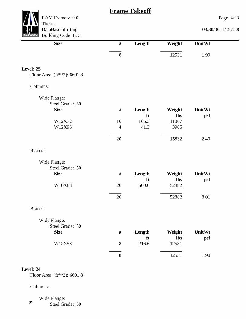
Frame TakeoffRAM Frame v10.0ThesisDataBase: drifting 03/30/06 14:57:58Building Code: IBC
Size # Length Weight UnitWt _____ _________
8 12531 1.90
Level: 25Floor Area (ft**2): 6601.8
Columns:
Wide Flange:Steel Grade: 50
Size # Length Weight UnitWt ft lbs psf
W12X72 16 165.3 11867W12X96 4 41.3 3965
_____ _________20 15832 2.40
Beams:
Wide Flange:Steel Grade: 50
Size # Length Weight UnitWt ft lbs psf
W10X88 26 600.0 52882 _____ _________
26 52882 8.01
Braces:
Wide Flange:Steel Grade: 50
Size # Length Weight UnitWt ft lbs psf
W12X58 8 216.6 12531 _____ _________
8 12531 1.90
Level: 24Floor Area (ft**2): 6601.8
Columns:
Wide Flange:Steel Grade: 50
Page 4/23

Frame TakeoffRAM Frame v10.0ThesisDataBase: drifting 03/30/06 14:57:58Building Code: IBC
Size # Length Weight UnitWt ft lbs psf
W12X72 16 165.3 11867W12X96 4 41.3 3965
_____ _________20 15832 2.40
Beams:
Wide Flange:Steel Grade: 50
Size # Length Weight UnitWt ft lbs psf
W10X60 2 40.0 2396W10X88 24 560.0 49357
_____ _________26 51752 7.84
Braces:
Wide Flange:Steel Grade: 50
Size # Length Weight UnitWt ft lbs psf
W12X58 8 216.6 12531 _____ _________
8 12531 1.90
Level: 23Floor Area (ft**2): 6601.8
Columns:
Wide Flange:Steel Grade: 50
Size # Length Weight UnitWt ft lbs psf
W12X72 16 165.3 11867W12X96 4 41.3 3965
_____ _________20 15832 2.40
Beams:
Wide Flange:Steel Grade: 50
Page 5/23
Frame TakeoffRAM Frame v10.0ThesisDataBase: drifting 03/30/06 14:57:58Building Code: IBC
Size # Length Weight UnitWt ft lbs psf
W10X88 26 600.0 52882 _____ _________
26 52882 8.01
Braces:
Wide Flange:Steel Grade: 50
Size # Length Weight UnitWt ft lbs psf
W12X58 8 216.6 12531 _____ _________
8 12531 1.90
Level: 22Floor Area (ft**2): 6601.8
Columns:
Wide Flange:Steel Grade: 50
Size # Length Weight UnitWt ft lbs psf
W12X72 16 165.3 11867W12X96 4 41.3 3965
_____ _________20 15832 2.40
Beams:
Wide Flange:Steel Grade: 50
Size # Length Weight UnitWt ft lbs psf
W10X88 26 600.0 52882 _____ _________
26 52882 8.01
Braces:
Wide Flange:Steel Grade: 50
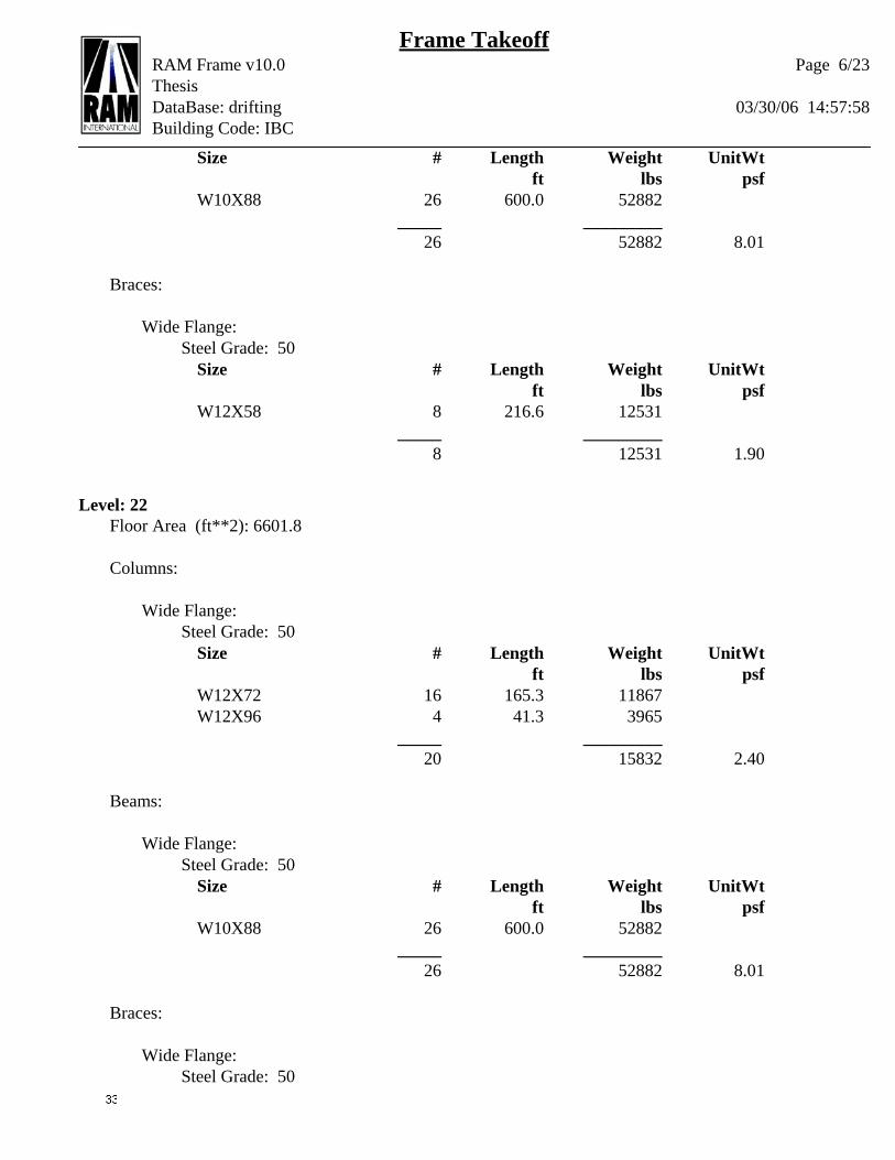
Page 6/23

Frame TakeoffRAM Frame v10.0ThesisDataBase: drifting 03/30/06 14:57:58Building Code: IBC
Size # Length Weight UnitWt ft lbs psf
W12X58 8 216.6 12531 _____ _________
8 12531 1.90
Level: 21Floor Area (ft**2): 13010.5
Columns:
Wide Flange:Steel Grade: 50
Size # Length Weight UnitWt ft lbs psf
W10X60 15 154.9 9280W12X72 11 113.6 8158W12X96 4 41.3 3965
_____ _________30 21403 1.65
Beams:
Wide Flange:Steel Grade: 50
Size # Length Weight UnitWt ft lbs psf
W10X45 1 20.0 905W10X77 43 1006.7 77420
_____ _________44 78325 6.02
Braces:
Wide Flange:Steel Grade: 50
Size # Length Weight UnitWt ft lbs psf
W12X58 12 318.8 18444 _____ _________
12 18444 1.42
Level: 20Floor Area (ft**2): 13010.5
Page 7/23

Frame TakeoffRAM Frame v10.0ThesisDataBase: drifting 03/30/06 14:57:58Building Code: IBC
Columns:
Wide Flange:Steel Grade: 50
Size # Length Weight UnitWt ft lbs psf
W10X60 14 144.6 8661W12X72 12 124.0 8900W12X96 4 41.3 3965
_____ _________30 21526 1.65
Beams:
Wide Flange:Steel Grade: 50
Size # Length Weight UnitWt ft lbs psf
W10X45 1 26.7 1207W10X77 43 1000.1 76907
_____ _________44 78114 6.00
Braces:
Wide Flange:Steel Grade: 50
Size # Length Weight UnitWt ft lbs psf
W12X58 12 318.8 18444 _____ _________
12 18444 1.42
Level: 19Floor Area (ft**2): 13010.5
Columns:
Wide Flange:Steel Grade: 50
Size # Length Weight UnitWt ft lbs psf
W10X60 12 124.0 7424W12X40 2 20.7 823W12X72 12 124.0 8900W12X96 4 41.3 3965
Page 8/23
Frame TakeoffRAM Frame v10.0ThesisDataBase: drifting 03/30/06 14:57:58Building Code: IBC
Size # Length Weight UnitWt _____ _________
30 21111 1.62
Beams:
Wide Flange:Steel Grade: 50
Size # Length Weight UnitWt ft lbs psf
W10X45 2 40.0 1810W10X77 42 986.7 75882
_____ _________44 77692 5.97
Braces:
Wide Flange:Steel Grade: 50
Size # Length Weight UnitWt ft lbs psf
W12X58 12 318.8 18444 _____ _________
12 18444 1.42
Level: 18Floor Area (ft**2): 13010.5
Columns:
Wide Flange:Steel Grade: 50
Size # Length Weight UnitWt ft lbs psf
W10X60 12 124.0 7424W12X72 14 144.6 10383W12X96 4 41.3 3965
_____ _________30 21772 1.67
Beams:
Wide Flange:Steel Grade: 50
Page 9/23

Frame TakeoffRAM Frame v10.0ThesisDataBase: drifting 03/30/06 14:57:58Building Code: IBC
Size # Length Weight UnitWt ft lbs psf
W10X45 1 20.0 905W10X77 43 1006.7 77420
_____ _________44 78325 6.02
Braces:
Wide Flange:Steel Grade: 50
Size # Length Weight UnitWt ft lbs psf
W12X58 12 318.8 18444 _____ _________
12 18444 1.42
Level: 17Floor Area (ft**2): 13010.5
Columns:
Wide Flange:Steel Grade: 50
Size # Length Weight UnitWt ft lbs psf
W10X60 12 124.0 7424W12X72 14 144.6 10383W12X96 4 41.3 3965
_____ _________30 21772 1.67
Beams:
Wide Flange:Steel Grade: 50
Size # Length Weight UnitWt ft lbs psf
W10X77 44 1026.7 78958 _____ _________
44 78958 6.07
Braces:
Wide Flange:Steel Grade: 50
Page 10/23

Frame TakeoffRAM Frame v10.0ThesisDataBase: drifting 03/30/06 14:57:58Building Code: IBC
Size # Length Weight UnitWt ft lbs psf
W12X58 12 318.8 18444 _____ _________
12 18444 1.42
Level: 16Floor Area (ft**2): 13010.5
Columns:
Wide Flange:Steel Grade: 50
Size # Length Weight UnitWt ft lbs psf
W10X60 12 124.0 7424W12X72 14 144.6 10383W12X96 4 41.3 3965
_____ _________30 21772 1.67
Beams:
Wide Flange:Steel Grade: 50
Size # Length Weight UnitWt ft lbs psf
W10X77 44 1026.7 78958 _____ _________
44 78958 6.07
Braces:
Wide Flange:Steel Grade: 50
Size # Length Weight UnitWt ft lbs psf
W12X58 12 318.8 18444 _____ _________
12 18444 1.42
Level: 15Floor Area (ft**2): 13010.5
Columns:
Page 11/23
Frame TakeoffRAM Frame v10.0ThesisDataBase: drifting 03/30/06 14:57:58Building Code: IBC
Wide Flange:Steel Grade: 50
Size # Length Weight UnitWt ft lbs psf
W10X60 12 124.0 7424W12X72 14 144.6 10383W12X96 4 41.3 3965
_____ _________30 21772 1.67
Beams:
Wide Flange:Steel Grade: 50
Size # Length Weight UnitWt ft lbs psf
W10X77 44 1026.7 78958 _____ _________
44 78958 6.07
Braces:
Wide Flange:Steel Grade: 50
Size # Length Weight UnitWt ft lbs psf
W12X58 12 318.8 18444 _____ _________
12 18444 1.42
Level: 14Floor Area (ft**2): 13010.5
Columns:
Wide Flange:Steel Grade: 50
Size # Length Weight UnitWt ft lbs psf
W10X60 12 124.0 7424W12X96 18 185.9 17842
_____ _________30 25266 1.94
Beams:
Page 12/23
Frame TakeoffRAM Frame v10.0ThesisDataBase: drifting 03/30/06 14:57:58Building Code: IBC
Wide Flange:Steel Grade: 50
Size # Length Weight UnitWt ft lbs psf
W10X77 44 1026.7 78958 _____ _________
44 78958 6.07
Braces:
Wide Flange:Steel Grade: 50
Size # Length Weight UnitWt ft lbs psf
W12X58 12 318.8 18444 _____ _________
12 18444 1.42
Level: 12Floor Area (ft**2): 13010.5
Columns:
Wide Flange:Steel Grade: 50
Size # Length Weight UnitWt ft lbs psf
W10X60 12 124.0 7424W12X96 18 185.9 17842
_____ _________30 25266 1.94
Beams:
Wide Flange:Steel Grade: 50
Size # Length Weight UnitWt ft lbs psf
W10X77 44 1026.7 78958 _____ _________
44 78958 6.07
Braces:
Wide Flange:Steel Grade: 50
Page 13/23
Frame TakeoffRAM Frame v10.0ThesisDataBase: drifting 03/30/06 14:57:58Building Code: IBC
Size # Length Weight UnitWt ft lbs psf
W12X58 12 318.8 18444 _____ _________
12 18444 1.42
Level: 11Floor Area (ft**2): 13010.5
Columns:
Wide Flange:Steel Grade: 50
Size # Length Weight UnitWt ft lbs psf
W10X60 12 124.0 7424W12X96 18 185.9 17842
_____ _________30 25266 1.94
Beams:
Wide Flange:Steel Grade: 50
Size # Length Weight UnitWt ft lbs psf
W10X77 44 1026.7 78958 _____ _________
44 78958 6.07
Braces:
Wide Flange:Steel Grade: 50
Size # Length Weight UnitWt ft lbs psf
W12X58 12 318.8 18444 _____ _________
12 18444 1.42
Level: 10Floor Area (ft**2): 13010.5
Columns:
Page 14/23
Frame TakeoffRAM Frame v10.0ThesisDataBase: drifting 03/30/06 14:57:58Building Code: IBC
Wide Flange:Steel Grade: 50
Size # Length Weight UnitWt ft lbs psf
W10X77 12 124.0 9533W12X96 18 185.9 17842
_____ _________30 27375 2.10
Beams:
Wide Flange:Steel Grade: 50
Size # Length Weight UnitWt ft lbs psf
W10X77 44 1026.7 78958 _____ _________
44 78958 6.07
Braces:
Wide Flange:Steel Grade: 50
Size # Length Weight UnitWt ft lbs psf
W12X58 12 318.8 18444 _____ _________
12 18444 1.42
Level: 9Floor Area (ft**2): 13010.5
Columns:
Wide Flange:Steel Grade: 50
Size # Length Weight UnitWt ft lbs psf
W10X77 12 124.0 9533W12X96 18 185.9 17842
_____ _________30 27375 2.10
Beams:
Wide Flange:
Page 15/23

Frame TakeoffRAM Frame v10.0ThesisDataBase: drifting 03/30/06 14:57:58Building Code: IBC
Steel Grade: 50Size # Length Weight UnitWt
ft lbs psfW10X88 44 1026.7 90487
_____ _________44 90487 6.95
Braces:
Wide Flange:Steel Grade: 50
Size # Length Weight UnitWt ft lbs psf
W12X58 12 318.8 18444 _____ _________
12 18444 1.42
Level: 8Floor Area (ft**2): 24264.8
Columns:
Wide Flange:Steel Grade: 50
Size # Length Weight UnitWt ft lbs psf
W10X88 26 277.4 24449W12X120 6 64.0 7690W14X120 18 192.1 23069
_____ _________50 55208 2.28
Beams:
Wide Flange:Steel Grade: 50
Size # Length Weight UnitWt ft lbs psf
W10X45 12 273.4 12371W10X88 68 1593.4 140431
_____ _________80 152802 6.30
Braces:
Wide Flange:
Page 16/23
Frame TakeoffRAM Frame v10.0ThesisDataBase: drifting 03/30/06 14:57:58Building Code: IBC
Steel Grade: 50Size # Length Weight UnitWt
ft lbs psfW12X58 18 456.5 26406
_____ _________18 26406 1.09
Level: 7Floor Area (ft**2): 24264.8
Columns:
Wide Flange:Steel Grade: 50
Size # Length Weight UnitWt ft lbs psf
W10X68 1 14.0 953W10X88 25 350.0 30846W12X120 6 84.0 10090W14X120 18 252.0 30269
_____ _________50 72157 2.97
Beams:
Wide Flange:Steel Grade: 50
Size # Length Weight UnitWt ft lbs psf
W10X45 11 253.4 11466W10X88 69 1613.4 142194
_____ _________80 153660 6.33
Braces:
Wide Flange:Steel Grade: 50
Size # Length Weight UnitWt ft lbs psf
W12X58 18 485.1 28061 _____ _________
18 28061 1.16
Page 17/23
Frame TakeoffRAM Frame v10.0ThesisDataBase: drifting 03/30/06 14:57:58Building Code: IBC
Level: 6Floor Area (ft**2): 24264.8
Columns:
Wide Flange:Steel Grade: 50
Size # Length Weight UnitWt ft lbs psf
W10X88 26 340.1 29971W12X120 6 78.5 9427W14X120 18 235.4 28280
_____ _________50 67678 2.79
Beams:
Wide Flange:Steel Grade: 50
Size # Length Weight UnitWt ft lbs psf
W10X45 12 273.4 12371W10X88 68 1593.4 140431
_____ _________80 152802 6.30
Braces:
Wide Flange:Steel Grade: 50
Size # Length Weight UnitWt ft lbs psf
W12X58 18 476.6 27570 _____ _________
18 27570 1.14
Level: 5Floor Area (ft**2): 24264.8
Columns:
Wide Flange:Steel Grade: 50
Page 18/23
Frame TakeoffRAM Frame v10.0ThesisDataBase: drifting 03/30/06 14:57:58Building Code: IBC
Size # Length Weight UnitWt ft lbs psf
W12X120 32 424.0 50929W14X120 18 238.5 28648
_____ _________50 79577 3.28
Beams:
Wide Flange:Steel Grade: 50
Size # Length Weight UnitWt ft lbs psf
W10X45 14 313.4 14181W10X88 66 1553.4 136906
_____ _________80 151087 6.23
Braces:
Wide Flange:Steel Grade: 50
Size # Length Weight UnitWt ft lbs psf
W12X58 18 478.1 27659 _____ _________
18 27659 1.14
Level: 4Floor Area (ft**2): 24264.8
Columns:
Wide Flange:Steel Grade: 50
Size # Length Weight UnitWt ft lbs psf
W12X120 32 424.0 50929W14X120 18 238.5 28648
_____ _________50 79577 3.28
Beams:
Wide Flange:Steel Grade: 50
Page 19/23

Frame TakeoffRAM Frame v10.0ThesisDataBase: drifting 03/30/06 14:57:58Building Code: IBC
Size # Length Weight UnitWt ft lbs psf
W10X45 14 320.0 14483W10X88 66 1546.8 136318
_____ _________80 150801 6.21
Braces:
Wide Flange:Steel Grade: 50
Size # Length Weight UnitWt ft lbs psf
W12X58 18 478.1 27659 _____ _________
18 27659 1.14
Level: 3Floor Area (ft**2): 24264.8
Columns:
Wide Flange:Steel Grade: 50
Size # Length Weight UnitWt ft lbs psf
W12X120 32 424.0 50929W14X120 18 238.5 28648
_____ _________50 79577 3.28
Beams:
Wide Flange:Steel Grade: 50
Size # Length Weight UnitWt ft lbs psf
W10X12 1 26.7 321W10X45 12 273.4 12371W10X88 67 1566.8 138081
_____ _________80 150773 6.21
Braces:
Wide Flange:
Page 20/23
Frame TakeoffRAM Frame v10.0ThesisDataBase: drifting 03/30/06 14:57:58Building Code: IBC
Steel Grade: 50Size # Length Weight UnitWt
ft lbs psfW12X58 18 478.1 27659
_____ _________18 27659 1.14
Level: 2Floor Area (ft**2): 24264.8
Columns:
Wide Flange:Steel Grade: 50
Size # Length Weight UnitWt ft lbs psf
W12X120 32 434.6 52198W14X120 18 244.4 29361
_____ _________50 81559 3.36
Beams:
Wide Flange:Steel Grade: 50
Size # Length Weight UnitWt ft lbs psf
W10X12 2 53.3 643W10X45 15 366.7 16595W10X88 13 346.7 30556W10X100 50 1100.1 110049
_____ _________80 157843 6.50
Braces:
Wide Flange:Steel Grade: 50
Size # Length Weight UnitWt ft lbs psf
W12X58 18 481.2 27834 _____ _________
18 27834 1.15
Page 21/23

Frame TakeoffRAM Frame v10.0ThesisDataBase: drifting 03/30/06 14:57:58Building Code: IBC
Level: 1Floor Area (ft**2): 24264.8
Columns:
Wide Flange:Steel Grade: 50
Size # Length Weight UnitWt ft lbs psf
W12X120 32 437.4 52544W14X120 18 246.1 29556
_____ _________50 82099 3.38
Beams:
Wide Flange:Steel Grade: 50
Size # Length Weight UnitWt ft lbs psf
W10X12 4 106.7 1285W10X45 76 1760.1 79656
_____ _________80 80941 3.34
Braces:
Wide Flange:Steel Grade: 50
Size # Length Weight UnitWt ft lbs psf
W12X58 18 482.0 27882 _____ _________
18 27882 1.15
TOTAL STRUCTURE FRAME TAKEOFF
Floor Area (ft**2): 388844.3
Columns:
Wide Flange:Steel Grade: 50
Page 22/23
Frame TakeoffRAM Frame v10.0ThesisDataBase: drifting 03/30/06 14:57:58Building Code: IBC
Size # Length Weight UnitWt ft lbs psf
W10X60 125 1291.3 77330W10X68 1 14.0 953W10X77 24 247.9 19065W10X88 77 967.5 85266W12X40 2 20.7 823W12X72 177 1818.4 130558W12X96 150 1558.2 149520W12X120 178 2370.5 284735W14X120 144 1885.5 226479
_____ _________878 974729 2.51
Beams:
Wide Flange:Steel Grade: 50
Size # Length Weight UnitWt ft lbs psf
W10X12 7 186.7 2249W10X45 171 3940.3 178321W10X60 3 66.7 3993W10X77 479 11187.5 860333W10X88 600 14054.4 1238617W10X100 52 1153.4 115385W12X106 6 133.3 14156
_____ _________1318 2413054 6.21
Braces:
Wide Flange:Steel Grade: 50
Size # Length Weight UnitWt ft lbs psf
W12X58 330 8781.2 507959W12X87 18 467.8 40750
_____ _________348 548709 1.41
Note: Length and Weight based on Centerline dimensions.
Page 23/23

Gravity Beam Design TakeoffRAM Steel v10.0ThesisDataBase: drifting 03/30/06 15:00:07Building Code: IBC Steel Code: ASD 9th Ed.
STEEL BEAM DESIGN TAKEOFF:
Floor Type: rfStory Level 28
Steel Grade: 50
SIZE # LENGTH (ft) WEIGHT (lbs)W8X10 6 122.68 1236W10X39 4 106.68 4175
----- ------------- 10 5410
Total Number of Studs = 108
Floor Type: ++Story Level 27
Steel Grade: 50
SIZE # LENGTH (ft) WEIGHT (lbs)W8X10 3 42.67 430W10X39 5 133.35 5218
----- ------------- 8 5648
Total Number of Studs = 97
Floor Type: 28Story Level 26
Steel Grade: 50
SIZE # LENGTH (ft) WEIGHT (lbs)W8X10 5 96.01 967W10X12 21 560.07 6747
----- ------------- 26 7714
Total Number of Studs = 224
Floor Type: 23-27Story Levels 21 to 25
Steel Grade: 50
Gravity Beam Design TakeoffRAM Steel v10.0ThesisDataBase: drifting 03/30/06 15:00:07Building Code: IBC Steel Code: ASD 9th Ed.
SIZE # LENGTH (ft) WEIGHT (lbs)W8X10 3 42.67 430W10X12 47 1253.49 15099W12X19 2 40.00 758
----- ------------- 52 16287
Total Number of Studs = 474
Floor Type: 9-22Story Levels 9 to 20
Steel Grade: 50
SIZE # LENGTH (ft) WEIGHT (lbs)W8X10 29 458.72 4620W10X12 81 2186.93 26343W12X19 2 40.00 758W16X26 2 96.15 2513W10X30 2 53.34 1604
----- ------------- 116 35839
Total Number of Studs = 1052
Floor Type: 8Story Level 8
Steel Grade: 50
SIZE # LENGTH (ft) WEIGHT (lbs)W8X10 34 399.31 4022W10X12 5 99.92 1204W12X14 64 1663.25 23544W12X16 6 139.30 2233W12X19 12 285.90 5419W14X22 87 2314.03 51103W16X26 3 74.63 1950W16X31 3 59.47 1848W18X35 5 140.01 4907W18X40 2 50.25 2018W21X44 1 35.41 1567W10X49 2 53.34 2614W24X62 1 26.30 1638
----- ------------- 225 104065
Page 2/3
Gravity Beam Design TakeoffRAM Steel v10.0ThesisDataBase: drifting 03/30/06 15:00:07Building Code: IBC Steel Code: ASD 9th Ed.
Total Number of Studs = 3512
Floor Type: 1-7Story Levels 1 to 7
Steel Grade: 50
SIZE # LENGTH (ft) WEIGHT (lbs)W8X10 58 902.69 9092W10X12 158 4206.23 50668W12X14 3 85.67 1213W12X19 2 40.00 758W14X22 1 26.30 581W10X30 1 26.67 802W10X49 2 53.34 2614
----- ------------- 225 65727
Total Number of Studs = 1962
TOTAL STRUCTURE GRAVITY BEAM TAKEOFF
Steel Grade: 50
SIZE # LENGTH (ft) WEIGHT (lbs)W8X10 817 12697.49 127892W10X12 2339 62614.26 754242W10X39 9 240.03 9393W10X49 16 426.72 20909W10X30 31 826.77 24870W12X14 85 2262.92 32033W12X16 6 139.30 2233W12X19 60 1245.90 23614W14X22 94 2498.16 55169W16X26 27 1228.45 32104W16X31 3 59.47 1848W18X35 5 140.01 4907W18X40 2 50.25 2018W21X44 1 35.41 1567W24X62 1 26.30 1638
----- ------------- 3496 1094435
Total Number of Studs = 32669
Page 3/3

Gravity Column Design TakeOffRAM Steel v10.0ThesisDataBase: drifting 03/30/06 15:00:03Building Code: IBC Steel Code: ASD 9th Ed.
Steel Grade: 50
I section
Size # Length (ft) Weight (lbs)
W10X33 34 915.5 30249W10X39 2 27.3 1066
_____ _________36 31315
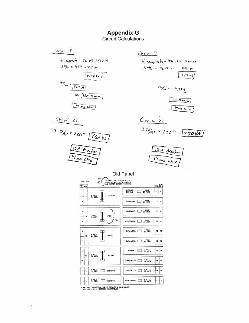
Appendix G Circuit Calculations
Old Panel

Appendix H Estimating Details
Existing Concrete Structure
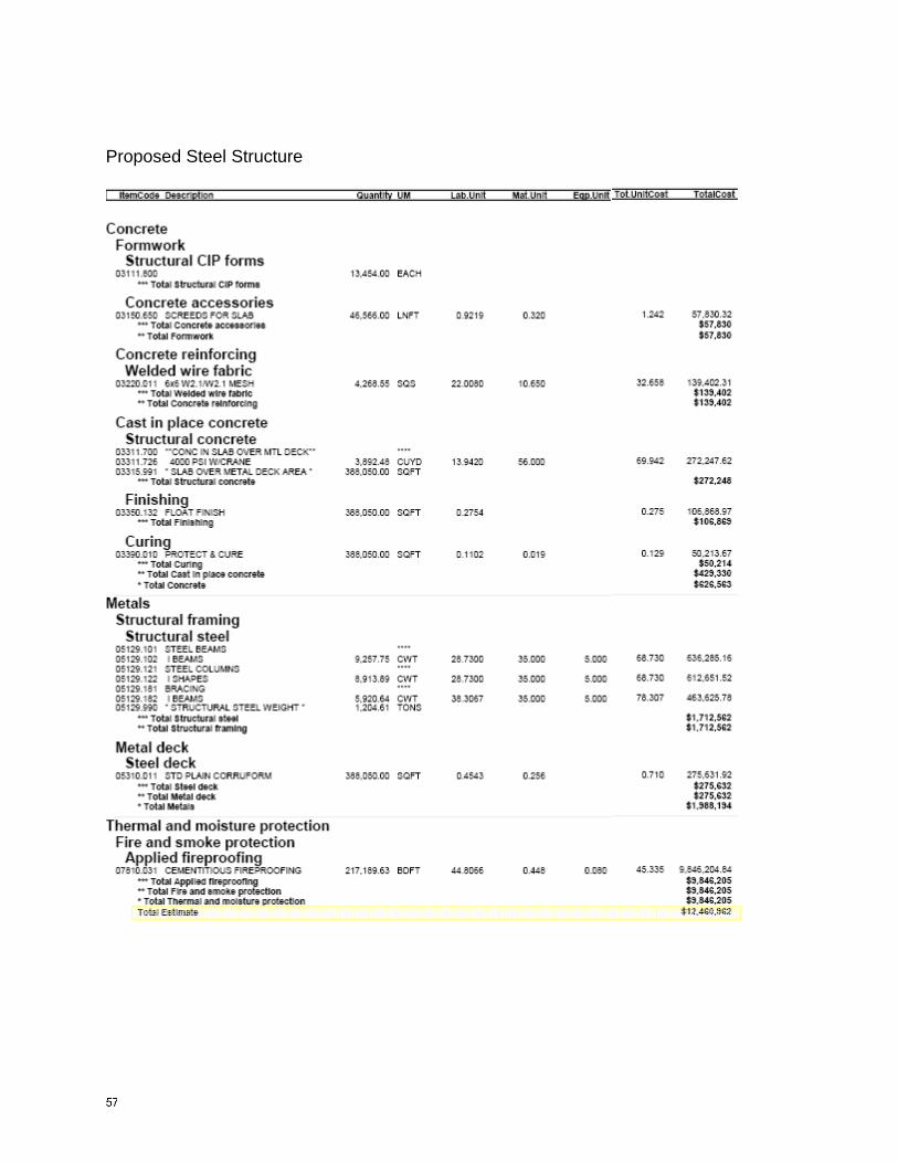
Proposed Steel Structure