metropolitan /m-94 - uspvh.com 35 2 metropolitan®/m-94 ... diana 2100 grease or an equivalent must...
TRANSCRIPT
Maintenance Guide
Metropolitan®/M-94 F i r e H y d r a n t
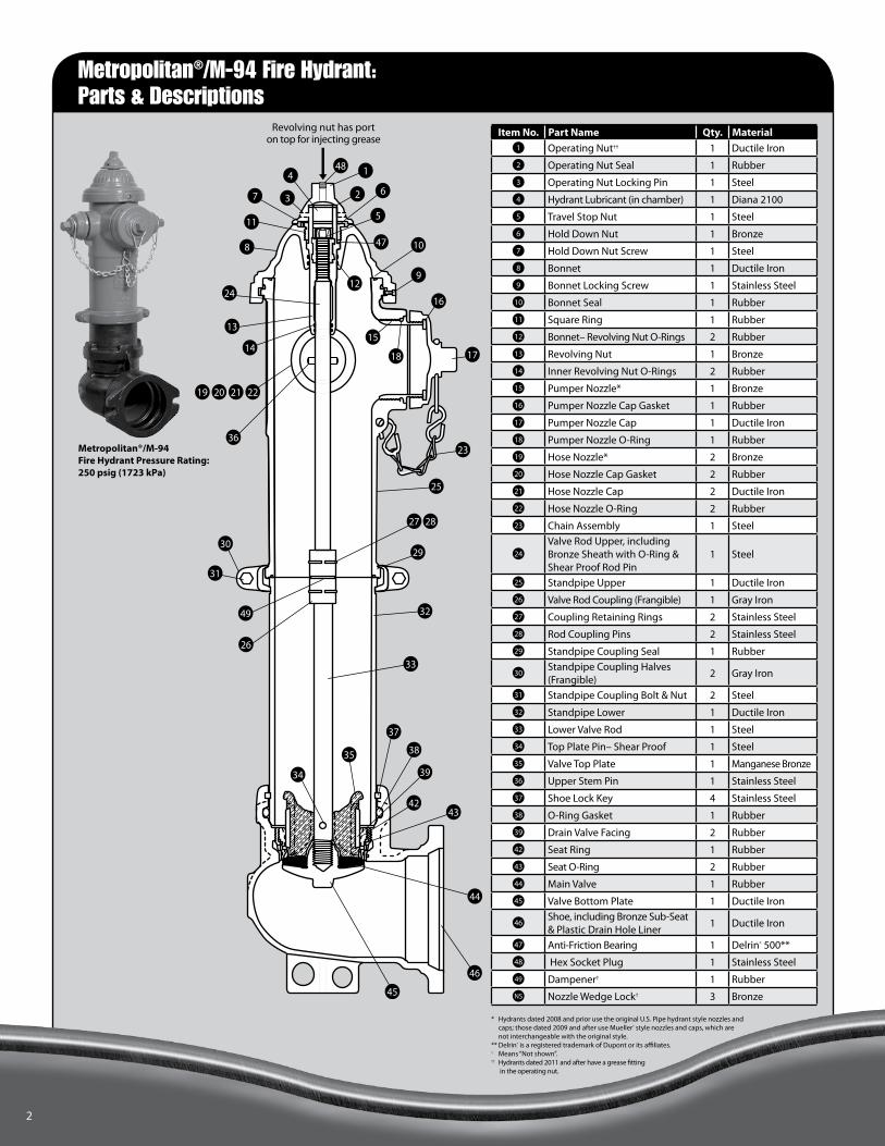
Revolving nut has port on top for injecting grease
13
14
24
11
1047
7
8
1
2 6
48
3
5
4
212019 22
17
16
9
32
29
25
23
30
31
27 28
26
49
46
44
45
4342
37
38
39
33
36
18
15
12
34
35
2
Metropolitan®/M-94 Fire Hydrant Pressure Rating: 250 psig (1723 kPa)
* Hydrants dated 2008 and prior use the original U.S. Pipe hydrant style nozzles and caps; those dated 2009 and after use Mueller® style nozzles and caps, which are not interchangeable with the original style.
** Delrin® is a registered trademark of Dupont or its affiliates.† Means “Not shown”.†† Hydrants dated 2011 and after have a grease fitting
in the operating nut.
Item No. Part Name Qty. Material1 Operating Nut†† 1 Ductile Iron
2 Operating Nut Seal 1 Rubber
3 Operating Nut Locking Pin 1 Steel
4 Hydrant Lubricant (in chamber) 1 Diana 2100
5 Travel Stop Nut 1 Steel
6 Hold Down Nut 1 Bronze
7 Hold Down Nut Screw 1 Steel
8 Bonnet 1 Ductile Iron
9 Bonnet Locking Screw 1 Stainless Steel
10 Bonnet Seal 1 Rubber
11 Square Ring 1 Rubber
12 Bonnet– Revolving Nut O-Rings 2 Rubber
13 Revolving Nut 1 Bronze
14 Inner Revolving Nut O-Rings 2 Rubber
15 Pumper Nozzle* 1 Bronze
16 Pumper Nozzle Cap Gasket 1 Rubber
17 Pumper Nozzle Cap 1 Ductile Iron
18 Pumper Nozzle O-Ring 1 Rubber
19 Hose Nozzle* 2 Bronze
20 Hose Nozzle Cap Gasket 2 Rubber
21 Hose Nozzle Cap 2 Ductile Iron
22 Hose Nozzle O-Ring 2 Rubber
23 Chain Assembly 1 Steel
24
Valve Rod Upper, includingBronze Sheath with O-Ring &Shear Proof Rod Pin
1 Steel
25 Standpipe Upper 1 Ductile Iron
26 Valve Rod Coupling (Frangible) 1 Gray Iron
27 Coupling Retaining Rings 2 Stainless Steel
28 Rod Coupling Pins 2 Stainless Steel
29 Standpipe Coupling Seal 1 Rubber
30Standpipe Coupling Halves(Frangible)
2 Gray Iron
31 Standpipe Coupling Bolt & Nut 2 Steel
32 Standpipe Lower 1 Ductile Iron
33 Lower Valve Rod 1 Steel
34 Top Plate Pin– Shear Proof 1 Steel
35 Valve Top Plate 1 Manganese Bronze
36 Upper Stem Pin 1 Stainless Steel
37 Shoe Lock Key 4 Stainless Steel
38 O-Ring Gasket 1 Rubber
39 Drain Valve Facing 2 Rubber
42 Seat Ring 1 Rubber
43 Seat O-Ring 2 Rubber
44 Main Valve 1 Rubber
45 Valve Bottom Plate 1 Ductile Iron
46Shoe, including Bronze Sub-Seat& Plastic Drain Hole Liner
1 Ductile Iron
47 Anti-Friction Bearing 1 Delrin® 500**
48 Hex Socket Plug 1 Stainless Steel
49 Dampener† 1 Rubber
NS Nozzle Wedge Lock† 3 Bronze
Metropolitan®/M-94 Fire Hydrant: Parts & Descriptions

3
CAUTION
All hydrants should be inspected and maintained as recommended per AWWA M17– latest revision. Hydrants should be lubricated or re-greased at least annually.
Hydrants dated 2010 and after include a standard grease fitting in the top of the op nut, and the following lubrication guidelines apply. Hydrants equipped with a grease fitting may be lubricated during routine flushing of hydrant.
1 With hydrant in closed position, remove grease fitting hex socket plug. Install grease zirk into port opening, before applying grease.
2 Apply 8 pumps of Diana 2100 food grade grease (or equivalent lubricant compatible with calcium sulfonate grease), using a common hand held grease gun.
3 Remove grease zirk after lubricating. Replace hex socket plug and operate hydrant.
Routine Inspection & Lubrication
Diana 2100 grease or an equivalent must be used to avoid creating a corrosive condition.For hydrants manufactured 2011 and before, follow instructions for Field Disassembly/Reassembly from Page 7 for removal of Revolving Nut only. Re-grease Revolving Nut and Stem threads, reassemble, and check for leaks as outlined in steps 8 & 9.
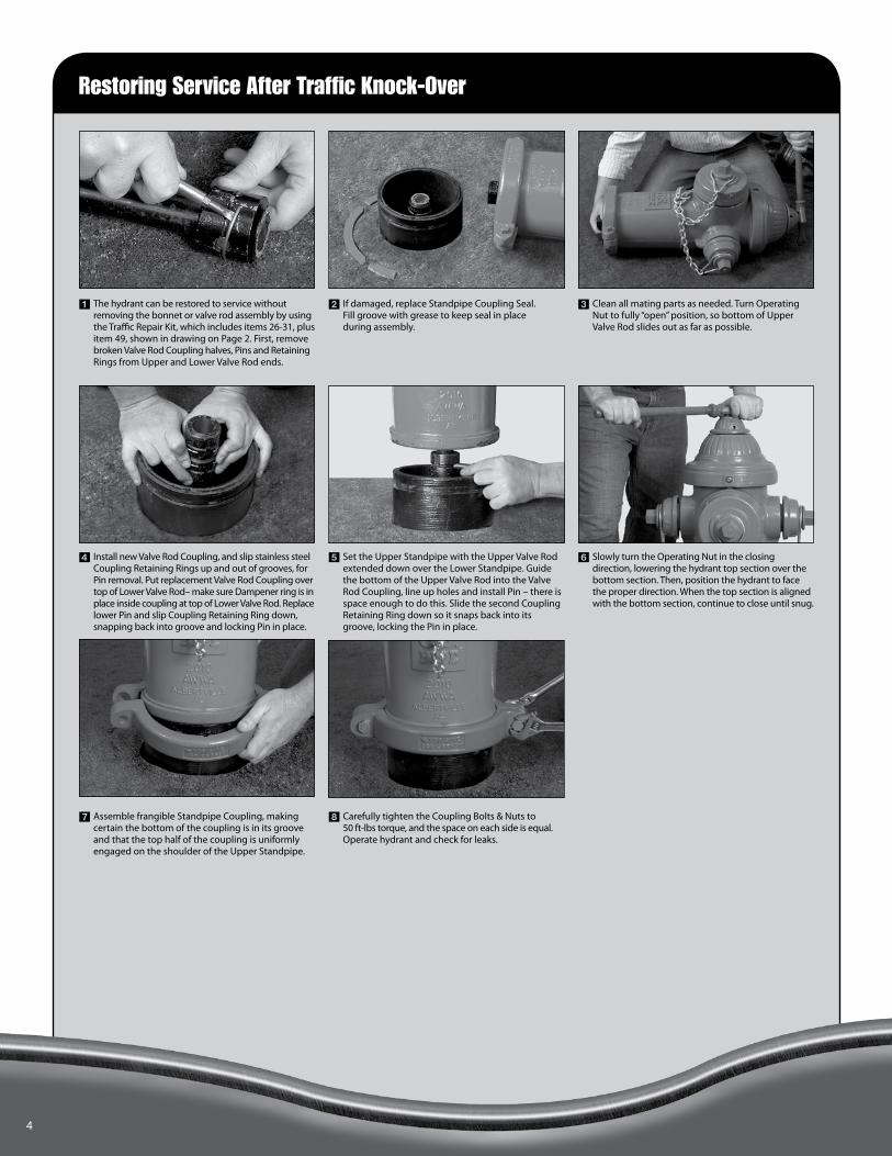
Restoring Service After Traffic Knock-Over
4
1 The hydrant can be restored to service without removing the bonnet or valve rod assembly by using the Traffic Repair Kit, which includes items 26-31, plus item 49, shown in drawing on Page 2. First, remove broken Valve Rod Coupling halves, Pins and Retaining Rings from Upper and Lower Valve Rod ends.
6 Slowly turn the Operating Nut in the closing direction, lowering the hydrant top section over the bottom section. Then, position the hydrant to face the proper direction. When the top section is aligned with the bottom section, continue to close until snug.
2 If damaged, replace Standpipe Coupling Seal. Fill groove with grease to keep seal in place during assembly.
4 Install new Valve Rod Coupling, and slip stainless steel Coupling Retaining Rings up and out of grooves, for Pin removal. Put replacement Valve Rod Coupling over top of Lower Valve Rod– make sure Dampener ring is in place inside coupling at top of Lower Valve Rod. Replace lower Pin and slip Coupling Retaining Ring down, snapping back into groove and locking Pin in place.
7 Assemble frangible Standpipe Coupling, making certain the bottom of the coupling is in its groove and that the top half of the coupling is uniformly engaged on the shoulder of the Upper Standpipe.
3 Clean all mating parts as needed. Turn Operating Nut to fully “open” position, so bottom of Upper Valve Rod slides out as far as possible.
5 Set the Upper Standpipe with the Upper Valve Rod extended down over the Lower Standpipe. Guide the bottom of the Upper Valve Rod into the Valve Rod Coupling, line up holes and install Pin – there is space enough to do this. Slide the second Coupling Retaining Ring down so it snaps back into its groove, locking the Pin in place.
8 Carefully tighten the Coupling Bolts & Nuts to 50 ft-lbs torque, and the space on each side is equal. Operate hydrant and check for leaks.

WARNING
Installing Extension Section
Before removing any bolt(s) holding the hydrant together, shut off the auxiliary hydrant control valve in order to isolate the hydrant from the main water source. Loosen (but do not remove) one Nozzle Cap two turns and check for water under pressure inside the hydrant– bleed off any excess pressure slowly, then remove Nozzle Cap completely. Open hydrant Main Valve completely. A continuous flow of water, no matter how slight, indicates that the hydrant is not properly isolated from the main water supply. That problem must be corrected before any hydrant disassembly can safely proceed. Disassembly of the hydrant with pressurized water forcing against the Main Valve could result in unexpected ejection of hydrant parts, debris or a high-pressure water stream, which could result in serious bodily injury.
5
55
5453
52
51
57
56
3Install Rod Extension between Upper and Lower Valve Rods, making sure that the non-frangible Extension Rod Coupling (without break groove) is below, and the frangible Valve Rod Coupling (with groove) is above. Be sure to reinstall Dampener ring between Extension and Frangible Couplings. Replace all Pins and secure each with stainless steel Coupling Retainer Rings.
6Place Upper Standpipe on Extension, taking care to keep Standpipe Coupling Seal in place during assembly.
1Depth of bury for this hydrant can be extended in 6” increments by using a standard Extension Kit, available from 6” to 36” in length. Longer lengths are special order. Follow steps 1 & 2 for bonnet removal on Page 7. Then, remove frangible Standpipe Coupling and lift Upper Standpipe over Valve Rod, taking care not to lose Coupling Seal in the process.
4Clean grooves in Lower Standpipe and Extension section. Install the Extension Coupling Gasket in groove on the bottom of the Extension. Either grease or gasket cement may be applied to keep it in place. Position the Extension over the Lower Standpipe.
7Reassemble frangible Standpipe Coupling around lip of Upper Standpipe and groove in the Extension. Make certain that there is uniform engagement all around– then, carefully tighten the Coupling Bolts & Nuts to 50 ft-lbs torque, and the space on each side is equal.
2Slide bottom Coupling Retaining Ring out of groove, remove bottom Rod Coupling Pin and separate Upper Valve Rod with Valve Rod Coupling still attached from Lower Valve Rod. Remove and save Dampener ring.
5Install Extension Standpipe Coupling with stainless steel Bolts & Nuts, so the grooves in both the Lower Standpipe and Extension are engaged equally, and bolts are tightened to 50 ft-lbs torque, and the space between ends of coupling are equal on both sides of hydrant.
8Make sure operating parts are clean and well lubricated before reassembly. Reassemble Bonnet onto extended Valve Rod assembly, following steps 7, 8 & 9 of the disassembly/reassembly procedure on Page 7.
Extension Kit includes the following:
51 Extension Rod Coupling Assembly
52 Rod Extension
53 Extension Coupling Gasket
54 Extension Standpipe Coupling Halves
55 Standpipe Extension
56 Extension Coupling Bolt & Nut
57 Dampener (not shown)

Rotating Hydrant to Face in Desired Direction
6
1 Open the hydrant Main Valve three turns.
4 Retighten the Bolts and Nuts on the frangible Standpipe Coupling. Make sure to carefully tighten them to 50 ft-lbs torque, and the spaces between the ends of each coupling half are equal.
2 Loosen, but do not completely disassemble the frangible Standpipe Coupling Bolts & Nuts.
5 Close the hydrant Main Valve first, then open the auxiliary hydrant control valve. Operate the hydrant and check for leaks.
3 Rotate the hydrant to the desired position.

Seat/ Main Valve Removal Procedure
WARNING
Before removing any bolt(s) holding the hydrant together, shut off the auxiliary hydrant control valve in order to isolate the hydrant from the main water source. Loosen (but do not remove) one Nozzle Cap two turns and check for water under pressure inside the hydrant – bleed off any excess pressure slowly, then remove Nozzle Cap completely. Open hydrant Main Valve completely. A continuous flow of water, no matter how slight, indicates that the hydrant is not properly isolated from the main water supply. That problem must be corrected before any hydrant disassembly can safely proceed. Disassembly of the hydrant with pressurized water forcing against the Main Valve could result in unexpected ejection of hydrant parts, debris or a high-pressure water stream, which could result in serious bodily injury.
7
7 Replace the Bonnet Seal. Grease threads on Upper Valve Rod. Replace the Bonnet, turning clockwise into locked position. Next, grease the threads on Bonnet Locking Screw and reinstall. Be certain that the Bonnet is centered, so locking screw sets in the “V” of the locking slot in the Upper Standpipe.
4 Remove and inspect rubber Main Valve. Remove bronze Seat Ring by sliding down off guides of Valve Top Plate – inspect and replace, if damaged. Replace Seat Ring O-Rings, if damaged.
1 Drive out Operating Nut Locking Pin from rounded side of Operating Nut. Remove Operating Nut, while taking care not to lose Operating Nut Seal, which is located inside the Operating Nut. With an 1/8” Allen wrench, loosen Hold Down Nut Screw – then remove Hold Down Nut using the Combination Spanner Wrench by turning counterclockwise.
2 Using socket of Combination Spanner Wrench or ¾” thinwall socket, remove Travel Stop Nut. Remove Revolving Nut – turn in operating direction of hydrant. It is not necessary to separate the Anti-friction Bearing from Revolving Nut. Using a 7/32” Allen wrench, remove Bonnet Locking Screw. With the Combination Spanner Wrench, rotate Bonnet 22.5º (1/16 turn) counter-clockwise. As lugs disengage, lift the Bonnet off the Valve Rod.
3 Remove Bonnet Seal. Using Seat Removal Wrench, unscrew the Valve Rod and Main Valve assembly, including bronze Seat Ring, by turning counterclockwise, and removing it as a unit. Holding Lower Valve Rod with a wrench, remove the Valve Bottom Plate.
5 Lay out all components, replacing worn, damaged ones as needed. Clean first, then grease all threaded parts, using a lubricant such as Diana 2100 (replacement grease must be compatible with calcium sulfonate grease). After lubrication, reassemble parts and securely tighten Bottom Valve Plate.
6 Reversing the above procedure, reinstall the Valve Rod and Main Valve assembly, fully threading it into the Seat Ring. To check for any leaks after being reinstalled, pull up on the Valve Rod to close the Main Valve– then, slowly open the auxiliary hydrant control valve to pressurize the elbow. Make sure seal is tight.
8 Re-grease both upper and lower chambers of Revolving Nut. Then, reinstall Hold Down Nut and tighten securely. Install and tighten Hold Down Nut Screw, and finally reinstall Operating Nut and Operating Nut Locking Pin.
9 Check pressure tightness of reassembled parts by following steps 2, 3 & 4 of AWWA certified inspection procedure. Following that, open the hydrant, allowing water to flow again. Close and check for proper drainage. If no problems are evident, the hydrant is already closed and considered back in service.

633 Chesnut StreetSuite 1200Chattanooga, TN 37450Phone: 800.871.2194Email: [email protected]: www.uspvh.com
Form 12699-rev 2/12-1M-1 ©2010 Mueller Co. Printed in USA
All products must be installed and maintained in accordance with applicable instructions and/or standards. All U.S. Pipe brochures and/or products are subject to change without notice.