metso knife gate valvevalveproducts.metso.com/documents/neles/technicalbulletins/en/4kh20en.pdf ·...
TRANSCRIPT

4KH20 EN
• 9/2019
METSO KNIFE GATE VALVE
Metso knife gate valve with bi-directional sealing. Suitable for mining and mineral processing applications. Stainless steel gate and removable rubber sleeves are part of robust design. High flow rate and tight shutoff provide optimal performance for different applications such as slurry transport, fluid transport or other abrasive and challenging applications.
TECHNICAL DESCRIPTIONSuitable for bi-directional operation, with abrasive and corrosive flow mediums. Wide range of different mate-rials for body, knives and sleeves offer most optimum solution to several different applications. Material selec-tion and valve sizing will ensure long operation life. Mounting between flanges will compress the sleeves or seals creating seal-tight fitting and smooth travel of knife. Metso knife gate valve can be delivered with integrated purge ports or according to other specified requirement. Flexible seats will protect the valve internal parts during the open position. Seat material selection is flow medium or other specified requirement.
APPLICATIONS□ Pump isolation□ Mineral processing concentrators□ Sand and gravel plants□ Tailing lines□ Hydro cyclone□ Slurry pipelines
VERSIONS, DETAILS□ Flange drilling PN 10 / ASME Class 150□ One-piece cast iron body□ Two rubber sleeves□ Bi-directional tightness (Rate A)□ Purge and flushing port available on request
Size range Working Δp
DN50 – DN600 10 kg/cm2
DN700 – DN1400 6 kg/cm2
DN80 – DN 900 21 kg/cm2 (High pressure series)
M E T S O
2 TECHNICAL BULLETIN 9/19
4 K H 2 0 E N
10
9
8
3
4
5
7
12
11
6
13
1
6
2
10
9
8
3
4
5
7
12
11
6
13
1
6
2
714
16
Part no.
Description Material
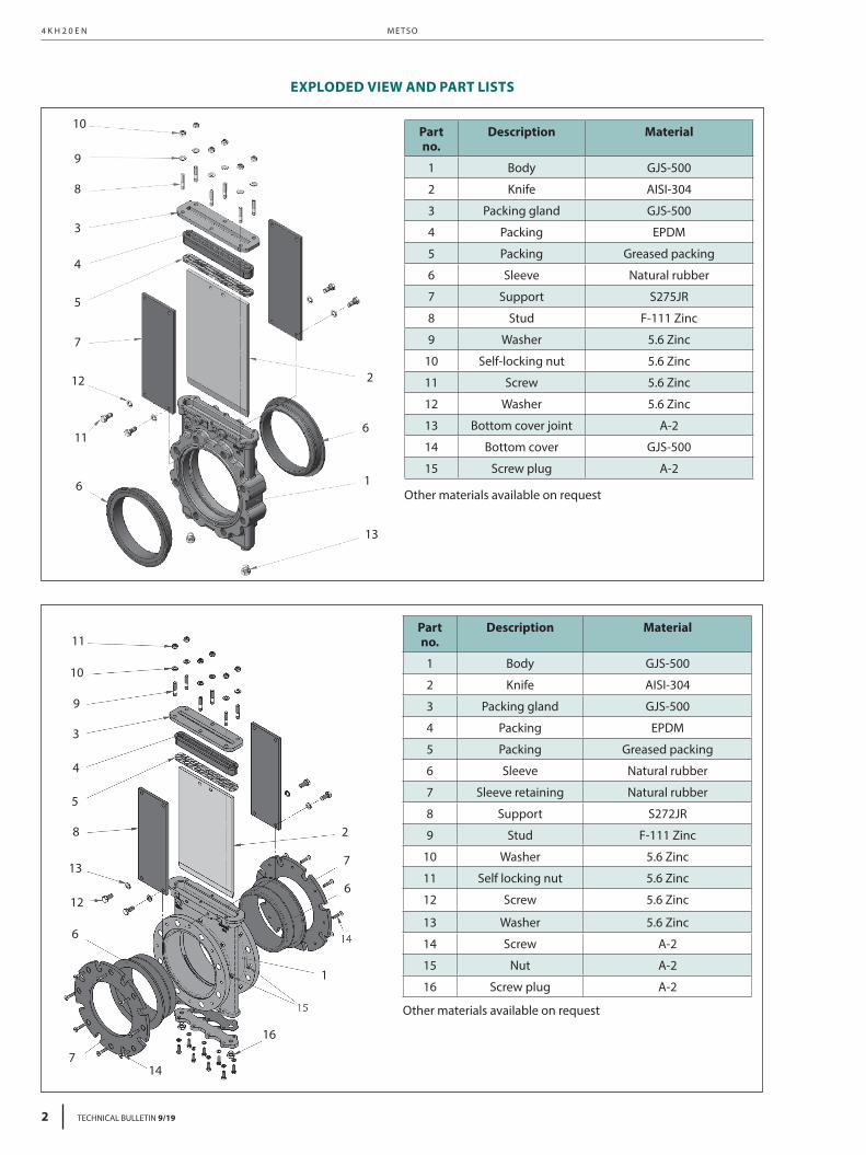
1 Body GJS-500
2 Knife AISI-304
3 Packing gland GJS-500
4 Packing EPDM
5 Packing Greased packing
6 Sleeve Natural rubber
7 Sleeve retaining Natural rubber
8 Support S272JR
9 Stud F-111 Zinc
10 Washer 5.6 Zinc
11 Self locking nut 5.6 Zinc
12 Screw 5.6 Zinc
13 Washer 5.6 Zinc
14 Screw A-2
15 Nut A-2
16 Screw plug A-2
Other materials available on request
Part no.
Description Material
1 Body GJS-500
2 Knife AISI-304
3 Packing gland GJS-500
4 Packing EPDM
5 Packing Greased packing
6 Sleeve Natural rubber
7 Support S275JR
8 Stud F-111 Zinc
9 Washer 5.6 Zinc
10 Self-locking nut 5.6 Zinc
11 Screw 5.6 Zinc
12 Washer 5.6 Zinc
13 Bottom cover joint A-2
14 Bottom cover GJS-500
15 Screw plug A-2
Other materials available on request
EXPLODED VIEW AND PART LISTS

TECHNICAL BULLETIN 9/19 3
K N I F E G AT E VA LV E 4 K H 2 0 E N
910
9
8
3
4
5
7
12
11
61
6
2
9
8
8
7
12
Part no.
Description Material
1 Body GJS-500
2 Knife AISI-316
3 Packing gland S275JR
4 Joint EPDM
5 Packing Greased packing
6 Bush Natural rubber
7 Support S275JR
8 Screw 5.6 Zinc
9 Washer ST Zinc
10 Cover joint EPDM
11 Lower cover S275JR
12 Greaser Steel
Other materials available on request
M E T S O
4 TECHNICAL BULLETIN 9/19
4 K H 2 0 E N
FC
A
B
ØDN
ØV
G D
N
ØK
ØDN
Screw depth P
Tapped holes
Through holes
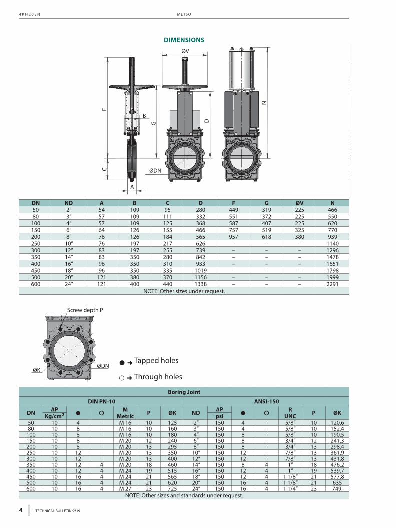
DIMENSIONS
DN ND A B C D F G ØV N50 2” 54 109 95 280 449 319 225 46680 3” 57 109 111 332 551 372 225 550
100 4” 57 109 125 368 587 407 225 620150 6” 64 126 155 466 757 519 325 770200 8” 76 126 184 565 957 618 380 939250 10” 76 197 217 626 – – – 1140300 12” 83 197 255 739 – – – 1296350 14” 83 350 280 842 – – – 1478400 16” 96 350 310 933 – – – 1651450 18” 96 350 335 1019 – – – 1798500 20” 121 380 370 1156 – – – 1999600 24” 121 400 440 1338 – – – 2291
NOTE: Other sizes under request.
Boring Joint
DIN PN-10 ANSI-150
DN ∆P • M Metric P ØK ND ∆P • R
UNC P ØKKg/cm2 psi50 10 4 – M 16 10 125 2” 150 4 – 5/8” 10 120.680 10 8 – M 16 10 160 3” 150 4 – 5/8” 10 152.4
100 10 8 – M 16 10 180 4” 150 8 – 5/8” 10 190.5150 10 8 – M 20 12 240 6” 150 8 – 3/4” 12 241.3200 10 8 – M 20 13 295 8” 150 8 – 3/4” 13 298.4250 10 12 – M 20 13 350 10” 150 12 – 7/8” 13 361.9300 10 12 – M 20 13 400 12” 150 12 – 7/8” 13 431.8350 10 12 4 M 20 18 460 14” 150 8 4 1” 18 476.2400 10 12 4 M 24 19 515 16” 150 12 4 1” 19 539.7450 10 16 4 M 24 21 565 18” 150 12 4 1 1/8” 21 577.8500 10 16 4 M 24 21 620 20” 150 16 4 1 1/8” 21 635600 10 16 4 M 27 23 725 24” 150 16 4 1 1/4” 23 749.
NOTE: Other sizes and standards under request.

TECHNICAL BULLETIN 9/19 5
K N I F E G AT E VA LV E 4 K H 2 0 E N
� ¢ Through holes
Flange thickness P
ØK ØDN
ØDN
ØV
A
CF
B
G D
N
Through holes
DIMENSIONS
DN ND A B C D F G ØV N50 2” 175 109 95 280 449 319 225 46680 3” 175 109 111 332 551 372 225 550
100 4” 175 109 125 368 587 407 225 620150 6” 178 126 155 466 757 519 325 770200 8” 184 126 184 565 957 618 380 939250 10” 225 197 217 626 – – – 1140300 12” 257 197 255 739 – – – 1296350 14” 257 350 280 842 – – – 1478400 16” 279 350 310 933 – – – 1651450 18” 311 350 335 1019 – – – 1798500 20” 359 380 370 1156 – – – 1999600 24” 372 400 440 1338 – – – 2291
NOTE: Other sizes under request.
Boring JointDIN PN-10 ANSI-150
DN ∆P M Metric P ØK ND ∆P R UNC P ØKKg/cm2 psi
50 10 4 M 16 32 125 2” 150 4 5/8” 32 120.680 10 8 M 16 32 160 3” 150 4 5/8” 32 152.4
100 10 8 M 16 32 180 4” 150 8 5/8” 32 190.5150 10 8 M 20 32 240 6” 150 8 3/4” 32 241.3200 10 8 M 20 33 295 8” 150 8 3/4” 33 298.4250 10 12 M 20 35 350 10” 150 12 7/8” 35 361.9300 10 12 M 20 37 400 12” 150 12 7/8” 37 431.8350 10 16 M 24 37 460 14” 150 12 1” 37 476.2400 10 16 M 24 41 515 16” 150 16 1” 41 539.7450 10 20 M 24 45 565 18” 150 16 1 1/8” 45 577.8500 10 20 M 24 46 620 20” 150 20 1 1/8” 46 635600 10 20 M 27 49 725 24” 150 20 1 1/4” 49 749.3
NOTE: Other sizes and standards under request.

M E T S O
6 TECHNICAL BULLETIN 9/19
4 K H 2 0 E N
ØDN
ØV
A
CF
B G D
N
� � Blind tapped holes
Screw depth P
ØK ØDN
Blind tapped holes
DIMENSIONS
Boring Joint
EN 1092-2 PN-25 ANSI B16,5, clase 300
DN ∆P • M Metric P ØK ND ∆P • R UNC P ØKKg/cm2 psi
80 21 8 M 16 20 160 3” 300 8 3/4” 0.79” 6.63”100 21 8 M 20 23 190 4” 300 8 3/4” 0.91” 7.87”150 21 8 M 24 27 250 6” 300 12 3/4” 1.06” 10.63”200 21 12 M 24 32 310 8” 300 12 7/8” 1.26” 13”250 21 12 M 27 35 370 10” 300 16 1” 1.38” 15.25”300 21 16 M 27 35 430 12” 300 16 1 1/8” 1.38” 17.75”350 21 16 M 30 38 490 14” 300 20 1 1/8” 1.50” 20.25”400 21 16 M 33 43 550 16” 300 20 1 1/4” 1.69” 22.5”450 21 20 M 33 48 600 18” 300 24 1 1/4” 1.89” 24.75”500 21 20 M 33 55 660 20” 300 24 1 1/4” 2.17” 27”600 21 20 M 36 55 770 24” 300 24 1 1/2” 2.17” 32”750 21 – – – – 30” 300 28 1 3/4” 2.17” 39.25”900 21 28 M 45 60 1090 36” 300 32 2” 2.36” 46”
NOTE: Other sizes and standards under request.
DN ND A B C D F G ØV N80 3” 176 109 125 362 529 401 225 593
100 4” 181 109 155 418 635 457 225 689150 6” 184 126 193 529 819 582 325 901200 8” 184 250 223 625 1022 744 450 1158250 10” 226 260 266 713 – – – 1370300 12” 242 275 296 812 – – – 1522350 14” 252 290 347 909 – – – 1667400 16” 287 320 376 1052 – – – 1785450 18” 311 350 401 1185 – – – 1875500 20” 373 350 436 1291 – – – 2160600 24” 362 350 515 1475 – – – 2410750 30” 413 375 625 1800 – – – –900 36” 467 400 710 2125 – – – –
NOTE: Other sizes under request.

TECHNICAL BULLETIN 9/19 7
K N I F E G AT E VA LV E 4 K H 2 0 E N
KNIFE GATE VALVE TYPECODE
1. 2. 3. 4. 5. 6. 7. 8.
KH L J 050 E A P D
1. VALVE SERIESKH Knife Gate Valve, Lug type, Bi-directional
2. END CONNECTIONL Lug
3. PRESSURE RATINGJ PN10C ASME Class 150
4. BODY SIZE050 DN 50 02 2”065 DN 65 2H 2.5”080 DN 80 03 3”100 DN 100 04 4”125 DN 125 05 Upon request150 DN 150 06 6”200 DN 200 08 8”250 DN 250 10 10”300 DN 300 12 12”350 DN 350 14 14”400 DN 400 16 16”450 DN 450 18 18”500 DN 500 20 20”600 DN 600 24 24”700 DN 700 28 28”
5. BODY MATERIALE GJS-500A CF8M
6. KNIFE, PACKING GLAND, PACKING, SEAT & BOTTOM COVER MATERIALS
A
Knife: AISI 304Packing gland: GJS-500Packing: Natural rubber, greased cottonSeat: Natural rubberBottom cover: GJS-500
B
Knife: AISI 316Packing gland: CF8MPacking: Natural rubber, greased cottonSeat: Natural rubberBottom cover: CF8M
7. ACTUATOR TYPEP PneumaticM Manual (handwheel with rising stem is standard if
nothing else is specified)
8. ACTUATOR SPECIFICATIOND Double acting
SOLENOID VALVE TYPECODE
1. 2. 3.
MW A 0242
1. MANUFACTURERMW Metalwork
2. MODELA SOV35SOSOO
3. COIL0242 W0215000101
LIMIT SWITCHES TYPECODE
1. 2. 3. 4.
M TM V 2
1. TYPEM MechanicalI Inductive
2. MANUFACTURERTM TelemecaniquePF Pepperl-Fuchs
3. MODELV XCK-M115 (Only for Telemecanique)A NBB8-18GM60-US (Only for Pepperl-Fuchs)
4. NUMBER OF SWITCHES2 2 Pieces

Subject to change without prior notice. Product names in thisbulletin are all trademarks of Metso Flow Control Inc.
Metso Corporation Töölönlahdenkatu 2, PO Box 1220, 00100 Helsinki, FinlandTel. +358 20 484 100http://contact.metso.com/
Metso Flow Control Inc.Vanha Porvoontie 229, P.O. Box 304, FI-01301 Vantaa, Finland.Tel. +358 20 483 150. Fax +358 20 483 151
www.metso.com/valves