mexico super mexico super cf495 - cf4140- ... frost protection ... boiler interlock.....7 for all...
TRANSCRIPT

installation and servicing
Mexico SuperYour Ideal installation and servicing guide
See reverse for Mexico Super users guide
ENGINEERED FOR PEACE OF MIND
When replacing any part on this appliance use only spare parts that you can be
assured conform to the safety and performance specification that we require. Do not
use reconditioned or copy parts that have not been clearly authorised by Ideal Boilers.
CF495, CF4120 & CF4140
May 2004 UIN 200 944 A02
200944-2.pmd 6/2/2004, 8:37 AM1

GENERAL
2 Mexico Super CF495 - CF4140 - Installation & Servicing
Boiler Size CF495 CF4120 CF4140
Boiler Input kW (Btu/h 34.2 (116 700) 43.1 (147 100) 50.1 (170 900)
Gas Consumption l/s (ft.3/h) 0.88 (112) 1.11 (142) 1.29 (165)
Boiler Output to Water kW (Btu/h 27.8 (95 000) 35.2 (120 000) 41.0 (140 000)
Burner SettingPressure (hot) mbar (in w.g.) 10.5 (4.2) 12.3 (4.9) 11.9 (4.8)
Flue Gas Flow Rate g/s 16.1 20.3 23.5
Flue Gas Temperature oC 115 112 115
Seasonal Efficiency (SEDBUK)* Band D [78.8]% [79.0]% [78.6]%
Boiler Size CF495 CF4120 CF4140
Gas Supply Connection in. BSP Rc 1/2 (1/2) Rc 3/4 (3/4)
Flue Connection mm (in.) 125 (5) 150 (6) 150 (6)
Number of Boiler Sections 4 5 6
Flow and Return Connections Rc 1 (1" BSP)
Maximum Static Water Head m (ft.) 30.5 (100) (3 bar)
Minimum Static Water Head m (ft.) 1.0 (3.3)
Gas Supply Pressure 20 mb
Gas Type Natural 2 H
Electrical Supply 230 V ~ 50 Hz
External Fuse Rating(Power Consumption) 3 A (10 W)
Water Content litre (gal.) 9.8 (2.1) 12.2 (2.7) 14.6 (3.2)
Dry Weight kg. (lb.) 112 (247) 132 (291) 155 (342)
Max. Inst Weight kg. (lb.) 102 (225) 120 (265) 142 (313)
Boiler Size Height mm (in.) 850 (33.5)
Width mm (in.) 440 (17.4)
Depth mm (in.) 533 (21.0) 600 (23.6) 750 (29.5)
Table 1 - General Data
Table 2 - Performance Data
Key to symbols
GB = United Kingdom (Countries ofIE = Ireland destination)
PMS = Maximum operating pressure of water
B11BS = An appliance designed for connection to a fluedischarging the products of combustion outside theroom, with air for combustion being drawn directly fromthe room where the appliance is installed, without a fanin the combustion products circuit and fitted with acombustion products discharge safety device.
I2H = An appliance designed for use on 2nd Family gas,Group H only.
Note.Gas consumption is calculated using a calorific valueof 38.7 MJ/m3 (1038 Btu/ft3) gross or 34.9 MJ/m3 (935Btu/ft3) nett
To obtain the gas consumption at a different calorificvalue:-
a. For l/s - divide the gross heat input (kW) by thegross C.V. of the gas (MJ/m3).
b. For ft3/h - divide the gross heat input (Btu/h) by thegross C.V. of the gas (Btu/ft3).
* The value is used in the UK government's Standard Assessment Procedure (SAP) for energy rating ofdwellings. The test data from which it has been calculated have been certified by Advantica 0087
CAUTION. To avoid the possibility of injury during the installation, servicing or cleaning of thisappliance, care should be taken when handling edges of sheet steel components.
200944-1.p65 3/8/2004, 3:41 PM2
GENERAL
3Mexico Super CF495 - CF4140 - Installation & Servicing
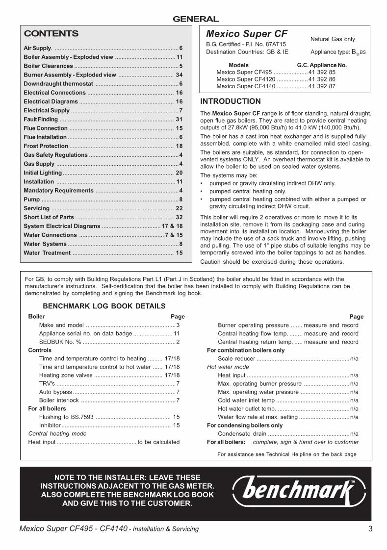
CONTENTSAir Supply. ............................................................................6Boiler Assembly - Exploded view ..................................... 11Boiler Clearances ................................................................5Burner Assembly - Exploded view .................................. 34Downdraught thermostat ...................................................6Electrical Connections ..................................................... 16Electrical Diagrams .......................................................... 16Electrical Supply ..................................................................7Fault Finding ...................................................................... 31Flue Connection ................................................................ 15Flue Installation ....................................................................6Frost Protection ................................................................ 18Gas Safety Regulations .......................................................4Gas Supply ...........................................................................4Initial Lighting .................................................................... 20Installation ......................................................................... 11Mandatory Requirements ...................................................4Pump ....................................................................................8Servicing ........................................................................... 22Short List of Parts ............................................................ 32System Electrical Diagrams .................................... 17 & 18Water Connections .................................................... 7 & 15Water Systems ....................................................................8Water Treatment .............................................................. 15
NOTE TO THE INSTALLER: LEAVE THESEINSTRUCTIONS ADJACENT TO THE GAS METER.ALSO COMPLETE THE BENCHMARK LOG BOOK
AND GIVE THIS TO THE CUSTOMER.
Mexico Super CFB.G. Certified - P.I. No. 87AT15Destination Countries: GB & IE Appliance type: B11BS
Models G.C. Appliance No.Mexico Super CF495 ..................... 41 392 85Mexico Super CF4120 ...................41 392 86Mexico Super CF4140 ...................41 392 87
Natural Gas only
BENCHMARK LOG BOOK DETAILSBoiler Page
Make and model .......................................................3Appliance serial no. on data badge ........................ 11SEDBUK No. % .........................................................2
ControlsTime and temperature control to heating ......... 17/18Time and temperature control to hot water ...... 17/18Heating zone valves .......................................... 17/18TRV's .........................................................................7Auto bypass ...............................................................7Boiler interlock ..........................................................7
For all boilersFlushing to BS.7593 .............................................. 15Inhibitor ................................................................... 15
Central heating modeHeat input ................................................. to be calculated
For assistance see Technical Helpline on the back page
PageBurner operating pressure ....... measure and recordCentral heating flow temp. ........ measure and recordCentral heating return temp. ..... measure and record
For combination boilers onlyScale reducer .........................................................n/a
Hot water modeHeat input ...............................................................n/aMax. operating burner pressure ............................n/aMax. operating water pressure ..............................n/aCold water inlet temp .............................................n/aHot water outlet temp. ............................................n/aWater flow rate at max. setting ...............................n/a
For condensing boilers onlyCondensate drain ..................................................n/a
For all boilers: complete, sign & hand over to customer
For GB, to comply with Building Regulations Part L1 (Part J in Scotland) the boiler should be fitted in accordance with themanufacturer's instructions. Self-certification that the boiler has been installed to comply with Building Regulations can bedemonstrated by completing and signing the Benchmark log book.
INTRODUCTIONThe Mexico Super CF range is of floor standing, natural draught,open flue gas boilers. They are rated to provide central heatingoutputs of 27.8kW (95,000 Btu/h) to 41.0 kW (140,000 Btu/h).The boiler has a cast iron heat exchanger and is supplied fullyassembled, complete with a white enamelled mild steel casing.The boilers are suitable, as standard, for connection to open-vented systems ONLY. An overheat thermostat kit is available toallow the boiler to be used on sealed water systems.The systems may be:� pumped or gravity circulating indirect DHW only.� pumped central heating only.� pumped central heating combined with either a pumped or
gravity circulating indirect DHW circuit.
This boiler will require 2 operatives or more to move it to itsinstallation site, remove it from its packaging base and duringmovement into its installation location. Manoeuvring the boilermay include the use of a sack truck and involve lifting, pushingand pulling. The use of 1" pipe stubs of suitable lengths may betemporarily screwed into the boiler tappings to act as handles.Caution should be exercised during these operations.
200944-1.p65 3/8/2004, 3:41 PM3
GENERAL
4 Mexico Super CF495 - CF4140 - Installation & Servicing
Operatives should be knowledgeable in handling techniqueswhen performing these tasks and the following precautionsshould be considered:� Split the boiler down to reduce the weight, e.g. remove casing
and hardware pack. Refer to Frame 9.� Be physically capable.� Use PPE as appropriate, e.g. gloves, safety footwear.During all manoeuvres and handling actions, every attemptshould be made to ensure the following unless unavoidableand/or the weight is light.� Keep back straight.� Avoid twisting at the waist.� Avoid upper body/top heavy bending.� Always grip with the palm of the hand.� Use designated hand holds.� Keep load as close to the body as possible.� Always use assistance if required.
OPTIONAL EXTRA KITSProgrammer Kit Fits neatly within the casing. Separate fitting
instructions are included with this kit.Overheat Is available to allow the boiler to be usedThermostat Kit on sealed water systems.
CURRENT GAS SAFETY (INSTALLATION AND USE)REGULATIONS OR RULES IN FORCE.The appliance is suitable only for installation in GB and IE andshould be installed in accordance with the rules in force.
In GB, the installation must be carried out by a CORGIRegistered Installer. It must be carried out in accordance withthe relevant requirements of the:� Gas Safety (Installation and Use) Regulations� The appropriate Building Regulations either The Building
Regulations, The Building Regulations (Scotland), BuildingRegulations (northern Ireland).
� The Water Fittings Regulations or Water byelaws in Scotland.� The Current I.E.E. Wiring Regulations.
Where no specific instructions are given, reference should bemade to the relevant British Standard Code of Practice.
In IE, the installation must be carried out by a Competent Personand installed in accordance with the current edition of I.S.813"Domestic Gas Installations", the current Building Regulationsand reference should be made to the current ETCI rules forelectrical installation.Detailed recommendations are contained in the following BritishStandard Codes of Practice:
BS. 6891 Low pressure installation pipes.BS. 6798 Installation of gas fired hot water boilers of rated
input not exceeding 60 kW.BS. 5449:1 Forced circulation hot water systems (small bore
and microbore domestic central heating systems).BS. 5546 Installation of gas hot water supplies for domestic
purposes (2nd Family Gases).BS. 5440: 1 Flues for gas appliances of rated input not
exceeding 60 kW.BS. 5440: 2 Ventilation for gas appliances of rated input not
exceeding 60 kW.BS 7593 Treatment of water in Domestic Hot Water Central
Heating Systems.Health and Safety Document No. 635.The Electricity at Work Regulations, 1989.Manufacturer�s notes must NOT be taken in any way asoverriding statutory obligations.
IMPORTANT. These appliances are certificated by the BritishStandards Institution for safety and performance. It isimportant, therefore, that no external control devices, e.g. fluedampers, economisers etc., are directly connected to theseappliances unless covered by these Installation and ServicingInstructions or otherwise recommended by Caradon IdealLimited in writing. If in doubt please enquire.Any direct connection of a control device not approved byCaradon Ideal Limited could invalidate the BSI Certificationand the normal appliance warranty. It could also infringe theGas Safety Regulations and the above regulations or otherstatutory requirements.
SAFE HANDLING OF SUBSTANCESCare should be taken when handling the boiler insulationpanels, which can cause irritation to the skin. No asbestos,mercury or CFCs are included in any part of the boiler.
LOCATION OF BOILERThe boiler must be installed on a flat and level floor, capable ofadequately supporting the weight of the boiler and any ancillaryequipment.
The boiler may be fitted on a combustible floor.
Insulation is not necessary, unless required by the local authority.
The boiler must not be fitted outside.The boiler must not be installed in a bedroom or in a roomcontaining a bath or shower.Timber Framed BuildingsIf the boiler is to be fitted in a timber framed building it shouldbe fitted in accordance with the Institute of Gas Engineeringdocument IGE/UP/7:1998.Compartment InstallationsA compartment used to enclose the boiler MUST be designedand constructed specially for this purpose.An existing cupboard or compartment may be used, providing itis modified for the purpose.Details of essential features of cupboard/compartment design,including airing cupboard installation, are to conform to thefollowing:!!!!! BS. 6798.!!!!! The position selected for installation MUST allow
adequate space for servicing in front of the boilerand for air circulation around the boiler.
! This position MUST also permit the provision of asatisfactory flue and an adequate air supply.
! For the minimum clearances required for safety andsubsequent service see Frame 2.
GAS SUPPLYThe local gas supplier should be consulted, at the installationplanning stage, in order to establish the availability of anadequate supply of gas. An existing service pipe must NOT beused without prior consultation with the local gas supplier.The boiler is to be installed only on a gas supply with agoverned meter.A gas meter can only be connected by the local gas supplier orby a local regional contractor.Check that the appliance is suitable for the proposed gassupply. An existing meter should be checked, preferably by thegas supplier, to ensure that the meter is adequate to deal withthe rate of gas supply required. A minimum gas pressure of20mbar MUST be available at the boiler inlet, with the boileroperating.Installation pipes MUST be fitted in accordance with BS. 6891.In IE refer to I.S. 813:2002. Pipework from the meter to the boilerMUST be of an adequate size.
200944-1.p65 3/8/2004, 3:41 PM4
GENERAL
5Mexico Super CF495 - CF4140 - Installation & Servicing
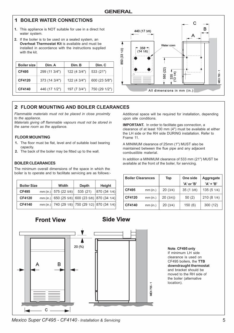
1 BOILER WATER CONNECTIONS
2 FLOOR MOUNTING AND BOILER CLEARANCES
1. This appliance is NOT suitable for use in a direct hotwater system.
2. If the boiler is to be used on a sealed system, anOverheat Thermostat Kit is available and must beinstalled in accordance with the instructions suppliedwith the kit.
Boiler size Dim. A Dim. B Dim. C
CF495 299 (11 3/4") 122 (4 3/4") 533 (21")
CF4120 373 (14 3/4") 122 (4 3/4") 600 (23 5/8")
CF4140 446 (17 1/2") 197 (7 3/4") 750 (29 1/2")
Flammable materials must not be placed in close proximityto the appliance.Materials giving off flammable vapours must not be stored inthe same room as the appliance.
Additional space will be required for installation, dependingupon site conditions.
IMPORTANT. In order to facilitate gas connection, aclearance of at least 100 mm (4") must be available at eitherthe LH side or the RH side DURING installation. Refer toFrame 11.
A MINIMUM clearance of 25mm (1") MUST also bemaintained between the flue pipe and any adjacentcombustible material.
In addition a MINIMUM clearance of 533 mm (21") MUST beavailable at the front of the boiler, for servicing.
Boiler Clearances Top One side Aggregate'A' or 'B' 'A' + 'B'
CF495 mm (in.) 20 (3/4) 35 (1 3/8) 135 (5 1/4)
CF4120 mm (in.) 20 (3/4)) 50 (2) 210 (8 1/4)
CF4140 mm (in.) 20 (3/4) 150 (6) 300 (12)
Note. CF495 onlyIf minimum LH sideclearance is used onCF495 boilers, the TTBdowndraught thermostatand bracket should bemoved to the RH side ofthe boiler (alternativelocation).
BOILER CLEARANCESThe minimum overall dimensions of the space in which theboiler is to operate and to facilitate servicing are as follows:-
Boiler Size Width Depth HeightCF495 mm (in.) 575 (22 5/8) 535 (21) 870 (34 1/4)
CF4120 mm (in.) 650 (25 5/8) 600 (23 5/8) 870 (34 1/4)
CF4140 mm (in.) 740 (29 1/8) 750 (29 1/2) 870 (34 1/4)
FLOOR MOUNTING1. The floor must be flat, level and of suitable load bearing
capacity.2. The back of the boiler may be fitted up to the wall.
200944-1.p65 3/8/2004, 3:41 PM5

GENERAL
6 Mexico Super CF495 - CF4140 - Installation & Servicing
The TTB is an automatic device which will reset once the windconditions have returned to normal, subject to a built-in resetdelay in excess of 10 minutes
The TTB is an important safety device and must not be put out ofaction or interfered with in any way.
This device is not a substitute for an independently mountedcarbon monoxide detector.
In cases of repeated or continuous shutdown a competentperson should be called to investigate and rectify the conditioncausing this and carry out an operational test after eachintervention on the device. Only the manufacturer's original partsshould be used for replacement.
AIR SUPPLYDetailed recommendations for air supply are given inBS.5440:2. In IE refer to I.S. 813:2002. The following notes arefor general guidance:
1. The room or internal space in which the boiler is installedMUST have, or be provided with, a permanent air vent. Thisvent MUST be either direct to outside air or to an adjacentroom or internal space which must itself have, or be providedwith, a permanent air vent at least the same size direct tooutside air.
The minimum effective area of the permanent air vent(s) arespecified in Table 3 and are related to maximum rated heatinput of the boiler.
The complete installation MUST be tested for gas soundnessand purged as described in the above code.
FLUE INSTALLATIONThe flue must be installed in accordance with therecommendations of BS. 5440-1:2000. In IE refer to I.S. 813:2002.
The following notes are intended for general guidance:
1. The cross-sectional area of the flue, serving the boiler, MUSTNOT be less than the area of the flue outlet of the boiler.
If flue pipe is to be used it MUST NOT be less than thediameter of the flue outlet connection on the boiler.
2. Flue pipes and fittings should be constructed from one of thefollowing materials:
a. Aluminium or stainless steel.
b. Cast iron, coated on the inside with acid resistant vitreousenamel.
c. Other approved material.
3. If twin walled flue pipe is used it should be of a typeacceptable to British Gas.
4. If a chimney is to be used it should preferably be one that iscomposed of, or lined with, a non-porous acid resistantmaterial.
Notes.Chimneys lined with salt -glazed earthenware pipes areacceptable if the pipes comply with BS.65 and BS.5440:1. A flue pipe constructed from one of the materials listed in2 a-c should form the initial connection to the lined chimneys.Where a chimney is to be used that is not composed of, orlined with, a non-porous, acid resistant material it should belined with a stainless steel flexible flue liner which complieswith BS.715.
5. Before connecting the boiler to, or inserting a liner into, a fluethat has been previously used then the flue MUST bethoroughly swept clean of any soot or loose material. If aregister plate, restrictor plate or damper etc., is fitted in theflue then it MUST be removed before connecting the boiler to,or inserting a liner into, the flue.
6. The flue should terminate in accordance with the relevantrecommendations given in BS.5440-1:2000. In IE refer toI.S.813:2002.
7. The flue MUST be fitted with a terminal (or ridge tile up to 5"flue diameter). The terminal shall be of a type which hasbeen tested and found satisfactory by British Gas. Thisterminal must NOT be installed within 600mm (24") of anopening window, air vent or any other ventilation opening.
8. The chimney / flue lining MUST be sealed at both the top andthe bottom.
IMPORTANT. It is absolutely ESSENTIAL to ensure, in practice,that the flue discharge is in a downdraught- free zone and thatproducts of combustion discharging from the terminal cannot re-enter the building or any other adjacent building throughventilators, windows, doors, other sources of natural airinfiltration or forced ventilation / air conditioning systems.
TTB DOWNDRAUGHT THERMOSTATThis appliance is fitted with a TTB downdraught thermostat foradded safety and protection. If this thermostat should operateand switch off the appliance it is because the flue is subject todowndraught, probably as a result of adverse wind conditions.
The air vent(s) must NOT have provision for closing oradjustment and should be sited to avoid risk of accidentaldamage or blockage.
If other methods of ventilation are envisaged, British Gasshould be consulted before proceeding.
2. If the boiler is to be installed in a cupboard or compartment,permanent air vents are required (for combustion, fluedilution and cooling purposes) in the cupboard /compartment, at both high and low levels to ensure safe andefficient combustion and ventilation.
The air vents may either communicate with room/internalspace (appropriately ventilated) or be direct to outside air.The minimum effective areas of the permanent air vents,required in the cupboard / compartment, are specified inTable 4 and are related to maximum rated heat input of theboiler.
Boiler size CF495 CF4120 CF4140
Effective 146 189 211areacm2 (in2) (23) (30) (32)
Table 3
Table 4 - High and low vent areas
Boiler Air from room/internal Air direct from outsidespace cm2 (in.2) cm2 (in.2)
High Level Low Level High level Low Level
CF495 354 (55) 708 (110) 177 (28) 354 (55)
CF4120 440 (69) 880 (138) 220 (35) 440 (69)
CF4140 485 (74) 970 (148) 243 (37) 485 (74)
200944-1.p65 3/8/2004, 3:41 PM6
GENERAL
7Mexico Super CF495 - CF4140 - Installation & Servicing
�����������
�����
�����
�����
�����
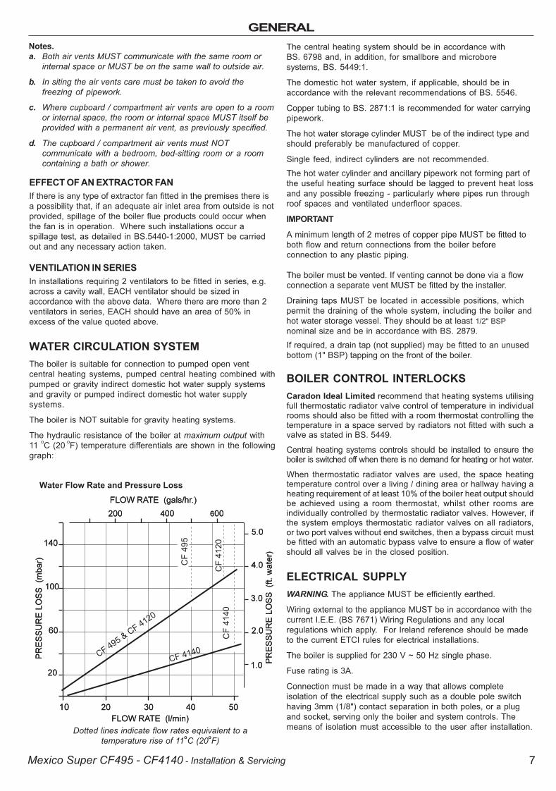
Dotted lines indicate flow rates equivalent to atemperature rise of 11oC (20oF)
EFFECT OF AN EXTRACTOR FANIf there is any type of extractor fan fitted in the premises there isa possibility that, if an adequate air inlet area from outside is notprovided, spillage of the boiler flue products could occur whenthe fan is in operation. Where such installations occur aspillage test, as detailed in BS.5440-1:2000, MUST be carriedout and any necessary action taken.
VENTILATION IN SERIESIn installations requiring 2 ventilators to be fitted in series, e.g.across a cavity wall, EACH ventilator should be sized inaccordance with the above data. Where there are more than 2ventilators in series, EACH should have an area of 50% inexcess of the value quoted above.
WATER CIRCULATION SYSTEMThe boiler is suitable for connection to pumped open ventcentral heating systems, pumped central heating combined withpumped or gravity indirect domestic hot water supply systemsand gravity or pumped indirect domestic hot water supplysystems.
The boiler is NOT suitable for gravity heating systems.
The hydraulic resistance of the boiler at maximum output with11 oC (20 oF) temperature differentials are shown in the followinggraph:
Water Flow Rate and Pressure Loss
The central heating system should be in accordance withBS. 6798 and, in addition, for smallbore and microboresystems, BS. 5449:1.
The domestic hot water system, if applicable, should be inaccordance with the relevant recommendations of BS. 5546.
Copper tubing to BS. 2871:1 is recommended for water carryingpipework.
The hot water storage cylinder MUST be of the indirect type andshould preferably be manufactured of copper.
Single feed, indirect cylinders are not recommended.The hot water cylinder and ancillary pipework not forming part ofthe useful heating surface should be lagged to prevent heat lossand any possible freezing - particularly where pipes run throughroof spaces and ventilated underfloor spaces.
IMPORTANT
A minimum length of 2 metres of copper pipe MUST be fitted toboth flow and return connections from the boiler beforeconnection to any plastic piping.
The boiler must be vented. If venting cannot be done via a flowconnection a separate vent MUST be fitted by the installer.
Draining taps MUST be located in accessible positions, whichpermit the draining of the whole system, including the boiler andhot water storage vessel. They should be at least 1/2" BSPnominal size and be in accordance with BS. 2879.If required, a drain tap (not supplied) may be fitted to an unusedbottom (1" BSP) tapping on the front of the boiler.
BOILER CONTROL INTERLOCKSCaradon Ideal Limited recommend that heating systems utilisingfull thermostatic radiator valve control of temperature in individualrooms should also be fitted with a room thermostat controlling thetemperature in a space served by radiators not fitted with such avalve as stated in BS. 5449.
Central heating systems controls should be installed to ensure theboiler is switched off when there is no demand for heating or hot water.
When thermostatic radiator valves are used, the space heatingtemperature control over a living / dining area or hallway having aheating requirement of at least 10% of the boiler heat output shouldbe achieved using a room thermostat, whilst other rooms areindividually controlled by thermostatic radiator valves. However, ifthe system employs thermostatic radiator valves on all radiators,or two port valves without end switches, then a bypass circuit mustbe fitted with an automatic bypass valve to ensure a flow of watershould all valves be in the closed position.
ELECTRICAL SUPPLYWARNING. The appliance MUST be efficiently earthed.
Wiring external to the appliance MUST be in accordance with thecurrent I.E.E. (BS 7671) Wiring Regulations and any localregulations which apply. For Ireland reference should be madeto the current ETCI rules for electrical installations.
The boiler is supplied for 230 V ~ 50 Hz single phase.
Fuse rating is 3A.
Connection must be made in a way that allows completeisolation of the electrical supply such as a double pole switchhaving 3mm (1/8") contact separation in both poles, or a plugand socket, serving only the boiler and system controls. Themeans of isolation must accessible to the user after installation.
Notes.a. Both air vents MUST communicate with the same room or
internal space or MUST be on the same wall to outside air.
b. In siting the air vents care must be taken to avoid thefreezing of pipework.
c. Where cupboard / compartment air vents are open to a roomor internal space, the room or internal space MUST itself beprovided with a permanent air vent, as previously specified.
d. The cupboard / compartment air vents must NOTcommunicate with a bedroom, bed-sitting room or a roomcontaining a bath or shower.
200944-1.p65 3/8/2004, 3:41 PM7

GENERAL
8 Mexico Super CF495 - CF4140 - Installation & Servicing
1. Open vent and cold feed connections must be made to theboiler flow and return tappings according to the optionsshown in Frame 11.
2. The boiler is assumed to be the highest point of thecirculating system.
3. The circulating pump is positioned on the FLOW and thevertical distance, between the pump and feed/expansiontank, must comply with the pump manufacturer's minimumrequirements, to avoid cavitation. Should these conditionsnot apply, either lower the pump position or raise the feed/expansion tank above the minimum requirements ofCaradon Ideal Limited.
4. The water velocity through the boiler flow / return pipes isassumed to be below 1 m/s (3 ft./s), whilst the pump flowrate is set to provide a temperature difference of 11 oC (20oF) across the boiler flow / return, at design input.
5. This information is intended as a GUlDE ONLY and cannottake into account instantaneous changes in head causedby the operation of motorised valves, pumps etc.
Due allowance MUST be made if surging is liable to occur.
If in any doubt, contact Caradon Ideal Limited.
3 MINIMUM REQUIREMENTS Fully pumped systems
4 GRAVITY HOT WATER & PUMPED CENTRAL HEATING1. Separate flow and return connections are used for each
service. All possible configurations are given in Frame11 and ONLY those shown should be used.
2. The schematic pipework graph is based on theassumption that NO MORE than 8 elbows are used inthe gravity loop, including entry to the boiler.
3. For each extra elbow in excess of 8 (R) MUST bereduced by 300 mm (12") or (H) increased by 100mm(4")
4. Whatever value is selected for (R), the value of (H)MUST be at least that indicated by the graph.
(R) = the horizontal distance between thecentre line of the cylinder and the boilertappings used - measured along the pipe run.
(H) = the vertical distance between the top of the boilerand the base of the cylinder.
Notes.
a. Flow and return pipes should rise vertically onleaving the boiler.
b. Horizontal pipes should be ABOVE ceiling leveland as short as possible.
c. A MINIMUM inclination of 25 mm per 3 m run (1"per 10') is required to avoid air locks.
If the above conditions cannot be met pumpedprimaries should be used.
�����
����
�����
�����
���� �
����
200944-1.p65 3/8/2004, 3:41 PM8
GENERAL
9Mexico Super CF495 - CF4140 - Installation & Servicing
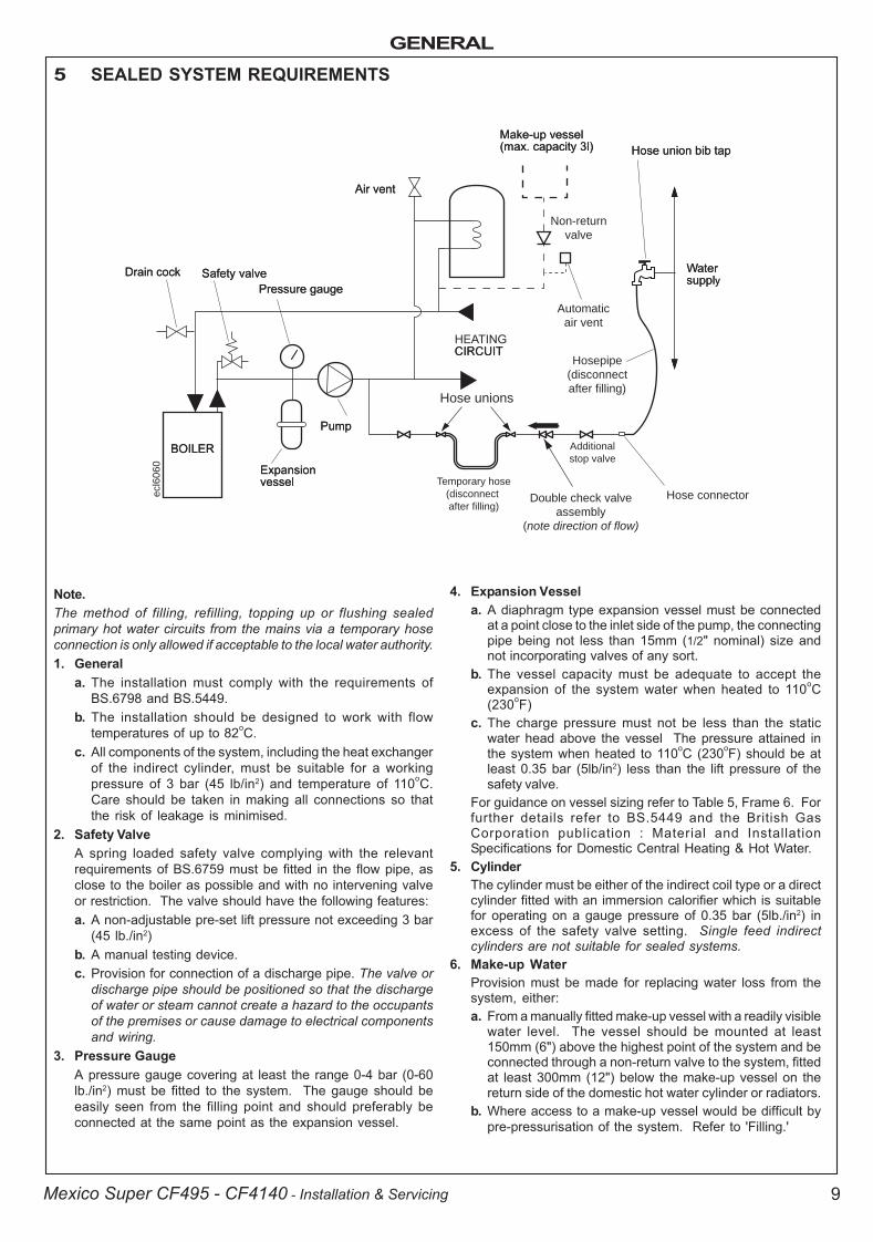
5 SEALED SYSTEM REQUIREMENTS
Note.The method of filling, refilling, topping up or flushing sealedprimary hot water circuits from the mains via a temporary hoseconnection is only allowed if acceptable to the local water authority.1. General
a. The installation must comply with the requirements ofBS.6798 and BS.5449.
b. The installation should be designed to work with flowtemperatures of up to 82oC.
c. All components of the system, including the heat exchangerof the indirect cylinder, must be suitable for a workingpressure of 3 bar (45 lb/in2) and temperature of 110oC.Care should be taken in making all connections so thatthe risk of leakage is minimised.
2. Safety ValveA spring loaded safety valve complying with the relevantrequirements of BS.6759 must be fitted in the flow pipe, asclose to the boiler as possible and with no intervening valveor restriction. The valve should have the following features:a. A non-adjustable pre-set lift pressure not exceeding 3 bar
(45 lb./in2)b. A manual testing device.c. Provision for connection of a discharge pipe. The valve or
discharge pipe should be positioned so that the dischargeof water or steam cannot create a hazard to the occupantsof the premises or cause damage to electrical componentsand wiring.
3. Pressure GaugeA pressure gauge covering at least the range 0-4 bar (0-60lb./in2) must be fitted to the system. The gauge should beeasily seen from the filling point and should preferably beconnected at the same point as the expansion vessel.
4. Expansion Vessela. A diaphragm type expansion vessel must be connected
at a point close to the inlet side of the pump, the connectingpipe being not less than 15mm (1/2" nominal) size andnot incorporating valves of any sort.
b. The vessel capacity must be adequate to accept theexpansion of the system water when heated to 110oC(230oF)
c. The charge pressure must not be less than the staticwater head above the vessel The pressure attained inthe system when heated to 110oC (230oF) should be atleast 0.35 bar (5lb/in2) less than the lift pressure of thesafety valve.
For guidance on vessel sizing refer to Table 5, Frame 6. Forfurther details refer to BS.5449 and the British GasCorporation publication : Material and InstallationSpecifications for Domestic Central Heating & Hot Water.
5. CylinderThe cylinder must be either of the indirect coil type or a directcylinder fitted with an immersion calorifier which is suitablefor operating on a gauge pressure of 0.35 bar (5lb./in2) inexcess of the safety valve setting. Single feed indirectcylinders are not suitable for sealed systems.
6. Make-up WaterProvision must be made for replacing water loss from thesystem, either:a. From a manually fitted make-up vessel with a readily visible
water level. The vessel should be mounted at least150mm (6") above the highest point of the system and beconnected through a non-return valve to the system, fittedat least 300mm (12") below the make-up vessel on thereturn side of the domestic hot water cylinder or radiators.
b. Where access to a make-up vessel would be difficult bypre-pressurisation of the system. Refer to 'Filling.'
Non-return
valve
Automatic
air vent
Hose unions
Additional
stop valve
Hose connector
Hosepipe
(disconnect
after filling)
Double check valve
assembly
(note direction of flow)
Temporary hose
(disconnect
after filling)
ecl6
060
200944-1.p65 3/8/2004, 3:41 PM9
GENERAL
10 Mexico Super CF495 - CF4140 - Installation & Servicing
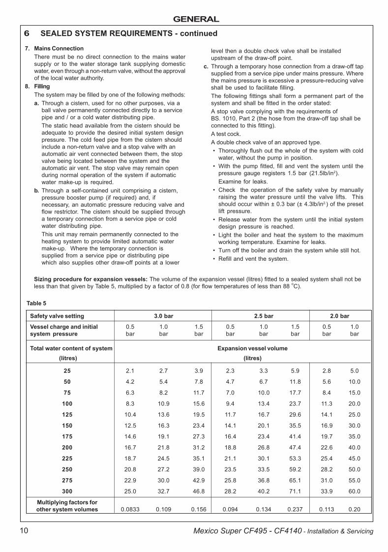
Sizing procedure for expansion vessels: The volume of the expansion vessel (litres) fitted to a sealed system shall not beless than that given by Table 5, multiplied by a factor of 0.8 (for flow temperatures of less than 88 oC).
Safety valve setting 3.0 bar 2.5 bar 2.0 bar
Vessel charge and initial 0.5 1.0 1.5 0.5 1.0 1.5 0.5 1.0system pressure bar bar bar bar bar bar bar bar
Total water content of system Expansion vessel volume (litres) (litres)
25 2.1 2.7 3.9 2.3 3.3 5.9 2.8 5.0
50 4.2 5.4 7.8 4.7 6.7 11.8 5.6 10.0
75 6.3 8.2 11.7 7.0 10.0 17.7 8.4 15.0
100 8.3 10.9 15.6 9.4 13.4 23.7 11.3 20.0
125 10.4 13.6 19.5 11.7 16.7 29.6 14.1 25.0
150 12.5 16.3 23.4 14.1 20.1 35.5 16.9 30.0
175 14.6 19.1 27.3 16.4 23.4 41.4 19.7 35.0
200 16.7 21.8 31.2 18.8 26.8 47.4 22.6 40.0
225 18.7 24.5 35.1 21.1 30.1 53.3 25.4 45.0
250 20.8 27.2 39.0 23.5 33.5 59.2 28.2 50.0
275 22.9 30.0 42.9 25.8 36.8 65.1 31.0 55.0
300 25.0 32.7 46.8 28.2 40.2 71.1 33.9 60.0
Multiplying factors forother system volumes 0.0833 0.109 0.156 0.094 0.134 0.237 0.113 0.20
7. Mains ConnectionThere must be no direct connection to the mains watersupply or to the water storage tank supplying domesticwater, even through a non-return valve, without the approvalof the local water authority.
8. FillingThe system may be filled by one of the following methods:a. Through a cistern, used for no other purposes, via a
ball valve permanently connected directly to a servicepipe and / or a cold water distributing pipe.The static head available from the cistern should beadequate to provide the desired initial system designpressure. The cold feed pipe from the cistern shouldinclude a non-return valve and a stop valve with anautomatic air vent connected between them, the stopvalve being located between the system and theautomatic air vent. The stop valve may remain openduring normal operation of the system if automaticwater make-up is required.
b. Through a self-contained unit comprising a cistern,pressure booster pump (if required) and, ifnecessary, an automatic pressure reducing valve andflow restrictor. The cistern should be supplied througha temporary connection from a service pipe or coldwater distributing pipe.This unit may remain permanently connected to theheating system to provide limited automatic watermake-up. Where the temporary connection issupplied from a service pipe or distributing pipewhich also supplies other draw-off points at a lower
level then a double check valve shall be installedupstream of the draw-off point.
c. Through a temporary hose connection from a draw-off tapsupplied from a service pipe under mains pressure. Wherethe mains pressure is excessive a pressure-reducing valveshall be used to facilitate filling.The following fittings shall form a permanent part of thesystem and shall be fitted in the order stated:A stop valve complying with the requirements ofBS. 1010, Part 2 (the hose from the draw-off tap shall beconnected to this fitting).A test cock.A double check valve of an approved type.� Thoroughly flush out the whole of the system with cold
water, without the pump in position.� With the pump fitted, fill and vent the system until the
pressure gauge registers 1.5 bar (21.5lb/in2).Examine for leaks.
� Check the operation of the safety valve by manuallyraising the water pressure until the valve lifts. Thisshould occur within ± 0.3 bar (± 4.3lb/in2.) of the presetlift pressure.
� Release water from the system until the initial systemdesign pressure is reached.
� Light the boiler and heat the system to the maximumworking temperature. Examine for leaks.
� Turn off the boiler and drain the system while still hot.� Refill and vent the system.
6 SEALED SYSTEM REQUIREMENTS - continued
Table 5
200944-1.p65 3/8/2004, 3:41 PM10
INSTALLATION
11Mexico Super CF495 - CF4140 - Installation & Servicing
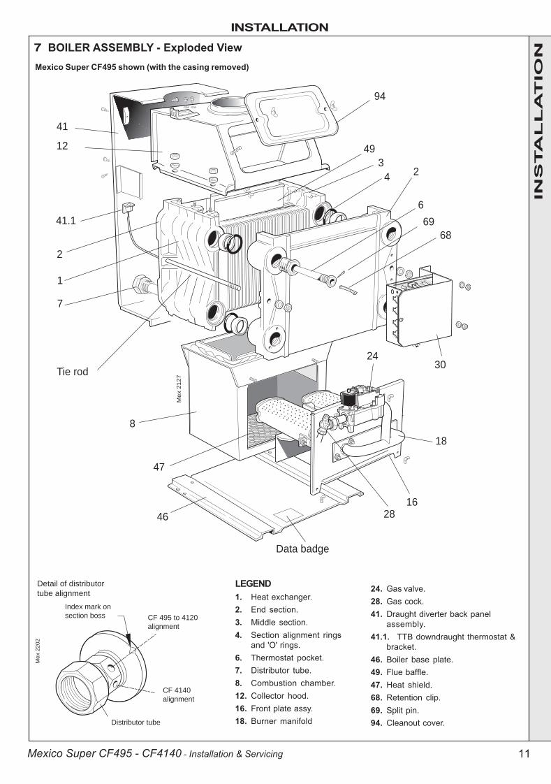
7 BOILER ASSEMBLY - Exploded ViewM
ex 2
202
Detail of distributor
tube alignment
Index mark on
section boss
Distributor tube
CF 495 to 4120
alignment
CF 4140
alignment
LEGEND1. Heat exchanger.2. End section.3. Middle section.4. Section alignment rings
and 'O' rings.6. Thermostat pocket.7. Distributor tube.8. Combustion chamber.12. Collector hood.16. Front plate assy.18. Burner manifold
24. Gas valve.28. Gas cock.41. Draught diverter back panel
assembly.41.1. TTB downdraught thermostat &
bracket.46. Boiler base plate.49. Flue baffle.47. Heat shield.68. Retention clip.69. Split pin.94. Cleanout cover.
94
49
41.1
2
1
7
Tie rod
8
46
Mex 2
127
Data badge
2816
18
30
6
69
68
24
3
24
12
41
47
Mexico Super CF495 shown (with the casing removed)
INS
TA
LL
AT
ION
200944-1.p65 3/8/2004, 3:41 PM11
INSTALLATION
12 Mexico Super CF495 - CF4140 - Installation & Servicing
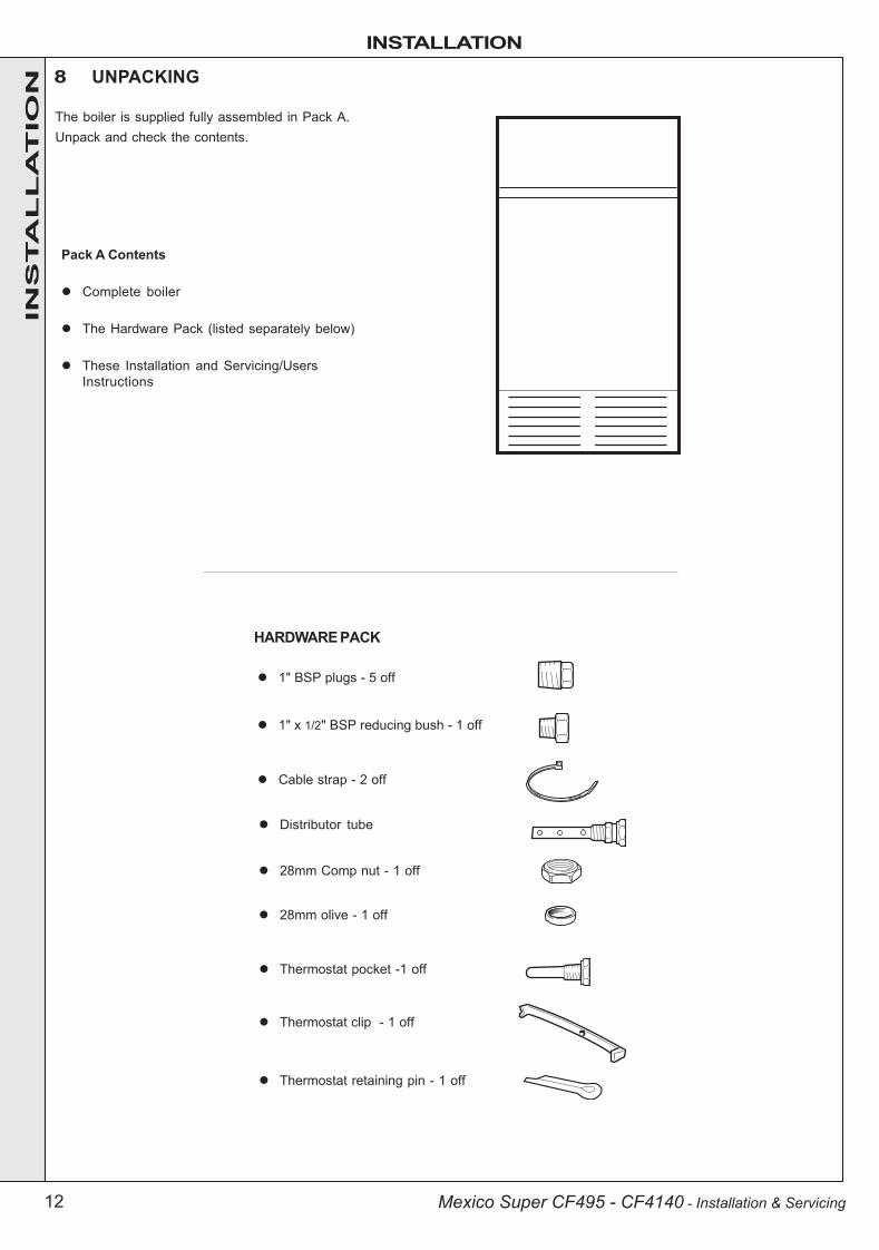
Pack A Contents
! Complete boiler
! The Hardware Pack (listed separately below)
! These Installation and Servicing/UsersInstructions
The boiler is supplied fully assembled in Pack A.Unpack and check the contents.
8 UNPACKING
HARDWARE PACK
! Thermostat pocket -1 off
! Thermostat clip - 1 off
! Thermostat retaining pin - 1 off
! 1" BSP plugs - 5 off
! 1" x 1/2" BSP reducing bush - 1 off
! Distributor tube
! Cable strap - 2 off
! 28mm Comp nut - 1 off
! 28mm olive - 1 off
INS
TA
LL
AT
ION
200944-1.p65 3/8/2004, 3:41 PM12
INSTALLATION
13Mexico Super CF495 - CF4140 - Installation & Servicing
ME
X 2
13
9
8
9 7
9
12
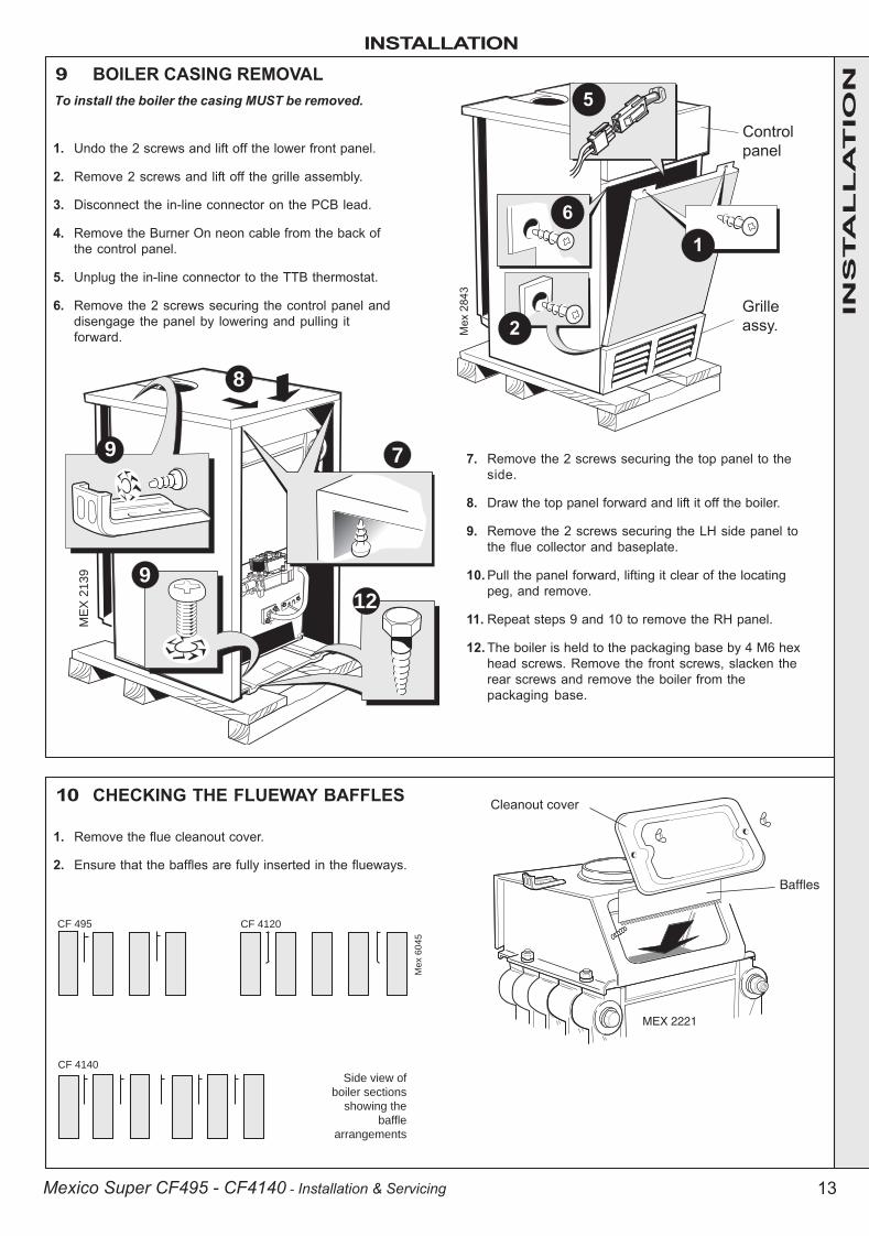
9 BOILER CASING REMOVALTo install the boiler the casing MUST be removed.
Me
x 6
04
5
Side view of
boiler sections
showing the
baffle
arrangements
CF 4140
CF 495 CF 4120
MEX 2221
Baffles
�������� ���
1. Remove the flue cleanout cover.
2. Ensure that the baffles are fully inserted in the flueways.
10 CHECKING THE FLUEWAY BAFFLES
1. Undo the 2 screws and lift off the lower front panel.
2. Remove 2 screws and lift off the grille assembly.
3. Disconnect the in-line connector on the PCB lead.
4. Remove the Burner On neon cable from the back ofthe control panel.
5. Unplug the in-line connector to the TTB thermostat.
6. Remove the 2 screws securing the control panel anddisengage the panel by lowering and pulling itforward.
7. Remove the 2 screws securing the top panel to theside.
8. Draw the top panel forward and lift it off the boiler.
9. Remove the 2 screws securing the LH side panel tothe flue collector and baseplate.
10. Pull the panel forward, lifting it clear of the locatingpeg, and remove.
11. Repeat steps 9 and 10 to remove the RH panel.
12. The boiler is held to the packaging base by 4 M6 hexhead screws. Remove the front screws, slacken therear screws and remove the boiler from thepackaging base.
INS
TA
LL
AT
ION
200944-1.p65 3/8/2004, 3:41 PM13
INSTALLATION
14 Mexico Super CF495 - CF4140 - Installation & Servicing
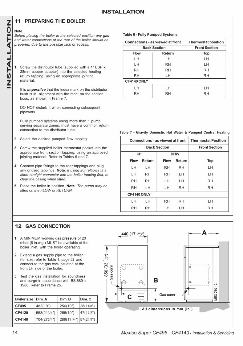
Boiler size Dim. A Dim. B Dim. C
CF495 482(19") 256(10") 28(11/8")
CF4120 553(213/4") 256(10") 47(17/8")
CF4140 704(273/4") 286(111/4") 57(21/4")
Connections - as viewed at front Thermostat Position
Back Section Front Section
CH DHW
Flow Return Flow Return Top
LH LH RH RH LH
LH RH RH LH LH
RH RH LH LH RH
RH LH LH RH RH
CF4140 ONLY
LH LH RH RH LH
RH RH LH LH RH
11 PREPARING THE BOILER
Note.Before placing the boiler in the selected position any gasand water connections at the rear of the boiler should beprepared, due to the possible lack of access.
1. Screw the distributor tube (supplied with a 1" BSP x28mm copper adaptor) into the selected heatingreturn tapping, using an appropriate jointingmaterial.
It is imperative that the index mark on the distributorbush is in alignment with the mark on the sectionboss, as shown in Frame 7.
DO NOT disturb it when connecting subsequentpipework.
Fully pumped systems using more than 1 pump,serving separate zones, must have a common returnconnection to the distributor tube.
2. Select the desired pumped flow tapping.
3. Screw the supplied boiler thermostat pocket into theappropriate front section tapping, using an approvedjointing material. Refer to Tables 6 and 7.
4. Connect pipe fittings to the rear tappings and plugany unused tappings. Note. If using iron elbows fit ashort straight connector into the boiler tapping first, toclear the casing when fitted.
5. Place the boiler in position. Note. The pump may befitted on the FLOW or RETURN.
Connections - as viewed at front Thermostat positionBack Section Front Section
Flow Return TopLH LH LHLH RH LHRH RH RHRH LH RH
CF4140 ONLY
LH LH LHRH RH RH
Table 6 - Fully Pumped Systems
Table 7 - Gravity Domestic Hot Water & Pumped Central Heating
12 GAS CONNECTION
1. A MINIMUM working gas pressure of 20mbar (8 in.w.g.) MUST be available at theboiler inlet, with the boiler operating.
2. Extend a gas supply pipe to the boiler(for size refer to Table 1, page 2) andconnect to the gas cock situated at thefront LH side of the boiler.
3. Test the gas installation for soundnessand purge in accordance with BS.6891:1988. Refer to Frame 25.
INS
TA
LL
AT
ION
200944-1.p65 3/8/2004, 3:41 PM14
INSTALLATION
15Mexico Super CF495 - CF4140 - Installation & Servicing
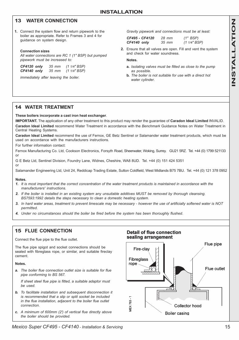
13 WATER CONNECTION
1. Connect the system flow and return pipework to theboiler as appropriate. Refer to Frames 3 and 4 forguidance on system design.
Connection sizesAll water connections are RC 1 (1" BSP) but pumpedpipework must be increased to:
CF4120 only 35 mm (1 1/4" BSP)CF4140 only 35 mm (1 1/4" BSP)
immediately after leaving the boiler.
Gravity pipework and connections must be at least:
CF495 - CF4120 28 mm (1" BSP)CF4140 only 35 mm (1 1/4" BSP)
2. Ensure that all valves are open. Fill and vent the systemand check for water soundness.
Notes.
a. Isolating valves must be fitted as close to the pumpas possible.
b. The boiler is not suitable for use with a direct hotwater cylinder.
15 FLUE CONNECTIONConnect the flue pipe to the flue outlet.
The flue pipe spigot and socket connections should besealed with fibreglass rope, or similar, and suitable fireclaycement.
Notes.
a. The boiler flue connection outlet size is suitable for fluepipe conforming to BS 567.
If sheet steel flue pipe is fitted, a suitable adaptor mustbe used.
b. To facilitate installation and subsequent disconnection itis recommended that a slip or split socket be includedin the flue installation, adjacent to the boiler flue outletconnection.
c. A minimum of 600mm (2') of vertical flue directly abovethe boiler should be provided.
14 WATER TREATMENTThese boilers incorporate a cast iron heat exchanger.IMPORTANT. The application of any other treatment to this product may render the guarantee of Caradon Ideal Limited INVALID.Caradon Ideal Limited recommend Water Treatment in accordance with the Benchmark Guidance Notes on Water Treatment inCentral Heating Systems.Caradon Ideal Limited recommend the use of Fernox, GE Betz Sentinel or Salamander water treatment products, which must beused on accordance with the manufacturers instructions.For further information contact:Fernox Manufacturing Co. Ltd, Cookson Electronics, Forsyth Road, Sheerwater, Woking, Surrey. GU21 5RZ. Tel. +44 (0) 1799 521133orG E Betz Ltd, Sentinel Division, Foundry Lane, Widnes, Cheshire, WA8 8UD. Tel. +44 (0) 151 424 5351orSalamander Engineering Ltd, Unit 24, Reddicap Trading Estate, Sutton Coldfield, West Midlands B75 7BU. Tel. +44 (0) 121 378 0952
Notes.1. It is most important that the correct concentration of the water treatment products is maintained in accordance with the
manufacturers' instructions.2. If the boiler is installed in an existing system any unsuitable additives MUST be removed by thorough cleansing.
BS7593:1992 details the steps necessary to clean a domestic heating system.3. In hard water areas, treatment to prevent limescale may be necessary - however the use of artificially softened water is NOT
permitted.4. Under no circumstances should the boiler be fired before the system has been thoroughly flushed.
INS
TA
LL
AT
ION
200944-1.p65 3/8/2004, 3:41 PM15

INSTALLATION
16 Mexico Super CF495 - CF4140 - Installation & Servicing
MEX 2129
�����������������
������� �
���
16 ELECTRICAL CONNECTIONS
17 INTERNAL WIRING
18 EXTERNAL CONTROLS
External wiring must be in accordance with the currentI.E.E. (BS 7671) Wiring Regulations. For Irelandreference should be made to the current ETCI rules forelectrical installations.The wiring diagrams illustrated in Frames 20-22 coverthe systems most likely to be fitted to this appliance.For wiring external controls to the Mexico Super CF boilerreference should be made to the system wiring diagramssupplied by the relevant manufacturer, in conjunction withthis flow wiring diagram and Frame 16.
Difficulty in wiring should not arise, providing thefollowing directions are observed:
3. If a proprietary system is used, follow the instructionssupplied by the manufacturer.
Advice on required modifications to the wiring may beobtained from the component manufacturers.
Note. If there are no external controls the circulating pumpMUST be wired into the control box.
1. Controls that switch the system on and off, e.g. a timeswitch, MUST be wired, in series, in the live mainslead to the boiler.
2. Controls that override an on/off control, e.g. a frostthermostat, MUST be wired into the mains lead, inparallel, with the control(s) to be overridden. Refer toFrame 23.
WARNING.The appliance MUST be efficiently earthed.A mains supply of 230 V ~ 50 Hz fused at 3A is required.All external controls and wiring MUST be suitable for mainsvoltage.Wiring should be in 3-core PVC insulated cable NOT LESS than0.75 mm2 (24 x 0.2 mm) to BS.6500, Table 16.Wiring external to the boiler MUST be in accordance with currentl.E.E. (BS 7671) Wiring Regulations and local regulations. ForIreland reference should be made to the current ETCI rules forelectrical installations.
Connection must be made in a way that allows completeisolation of the electrical supply - such as a double poleswitch, having a 3mm (1/8") contact separation in both poles,or a plug and socket serving only the boiler and systemcontrols.The means of isolation must be accessible to the user afterinstallation (except in the case of bathroom installations fordomestic boilers where the point of connection to the mainsMUST be outside of the bathroom).
TTB
MEX 2130
Fro
m s
yste
ms c
on
tro
ls
Boiler thermostat
Gas valve
PCB
Flow wiring diagram
Flow and pictorial wiring diagrams are shownin Frames 18 and 19.
1. Remove the securing screw and lift off thecontrol box cover.
2. Route the electrical leads into the box andwire into the terminal strip, as shown.
Notes.
a. Secure each lead with one of the cableclamps.
b. The mains lead connection MUST be madeso that, should the lead slip from itsanchorage, the current conductors becometaut before the earthing conductor.
LEGENDw whitebk blackbr brownb bluey/g yellow/green
INS
TA
LL
AT
ION
200944-1.p65 3/8/2004, 3:41 PM16
INSTALLATION
17Mexico Super CF495 - CF4140 - Installation & Servicing
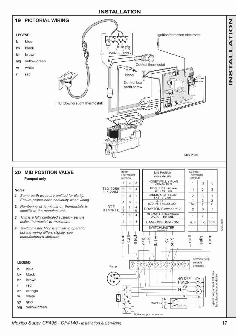
19 PICTORIAL WIRING
LEGEND
b blue
bk black
br brown
y/g yellow/green
w white
r red
Pumped only20 MID POSITION VALVE
LEGEND
b bluebk blackbr brownr redor orangew whitegy greyy/g yellow/green
ME
X 2
13
2
RoomThermostatTerminal
Mid Position
valve details
Cylinder Thermostat Terminal
Boiler supply connector
Pump
Terminal strip
suitably
enclosed
Typic
al pro
gra
mm
er
CH
may
be s
ele
cte
d independently
MAINS
Notes.1. Some earth wires are omitted for clarity.
Ensure proper earth continuity when wiring.
2. Numbering of terminals on thermostats isspecific to the manufacturer.
3. This is a fully controlled system - set theboiler thermostat to maximum.
4. 'Switchmaster Midi' is similar in operationbut the wiring differs slightly; seemanufacturer's literature.
INS
TA
LL
AT
ION
200944-1.p65 3/8/2004, 3:41 PM17
INSTALLATION
18 Mexico Super CF495 - CF4140 - Installation & Servicing
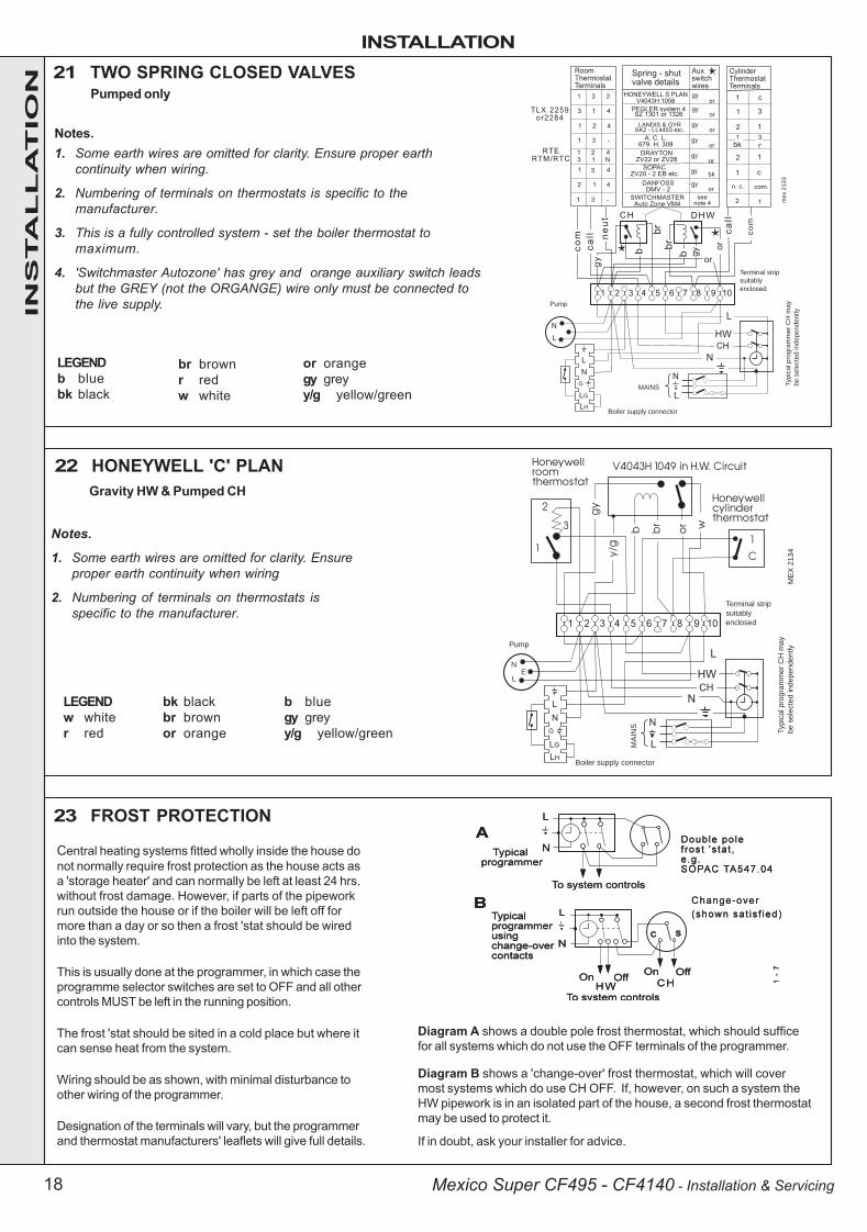
21 TWO SPRING CLOSED VALVES
Notes.1. Some earth wires are omitted for clarity. Ensure proper earth
continuity when wiring.
2. Numbering of terminals on thermostats is specific to themanufacturer.
3. This is a fully controlled system - set the boiler thermostat tomaximum.
4. 'Switchmaster Autozone' has grey and orange auxiliary switch leadsbut the GREY (not the ORGANGE) wire only must be connected tothe live supply.
LEGENDb bluebk black
Boiler supply connector
Pump
Terminal strip
suitably
enclosed
Typic
al pro
gra
mm
er
CH
may
be s
ele
cte
d independently
MAINS
me
x 2
13
3
Pumped only
22 HONEYWELL 'C' PLAN
Notes.
1. Some earth wires are omitted for clarity. Ensureproper earth continuity when wiring
2. Numbering of terminals on thermostats isspecific to the manufacturer.
LEGENDw whiter red
bk blackbr brownor orange
b bluegy greyy/g yellow/green
Boiler supply connector
Pump
Terminal strip
suitably
enclosed
Typic
al pro
gra
mm
er
CH
may
be s
ele
cte
d independently
MA
INS
ME
X 2
134
EN
L
23 FROST PROTECTION
br brownr redw white
or orangegy greyy/g yellow/green
Gravity HW & Pumped CH
Diagram A shows a double pole frost thermostat, which should sufficefor all systems which do not use the OFF terminals of the programmer.
Diagram B shows a 'change-over' frost thermostat, which will covermost systems which do use CH OFF. If, however, on such a system theHW pipework is in an isolated part of the house, a second frost thermostatmay be used to protect it.
If in doubt, ask your installer for advice.
Central heating systems fitted wholly inside the house donot normally require frost protection as the house acts asa 'storage heater' and can normally be left at least 24 hrs.without frost damage. However, if parts of the pipeworkrun outside the house or if the boiler will be left off formore than a day or so then a frost 'stat should be wiredinto the system.
This is usually done at the programmer, in which case theprogramme selector switches are set to OFF and all othercontrols MUST be left in the running position.
The frost 'stat should be sited in a cold place but where itcan sense heat from the system.
Wiring should be as shown, with minimal disturbance toother wiring of the programmer.
Designation of the terminals will vary, but the programmerand thermostat manufacturers' leaflets will give full details.
INS
TA
LL
AT
ION
200944-1.p65 3/8/2004, 3:41 PM18
INSTALLATION
19Mexico Super CF495 - CF4140 - Installation & Servicing
WARNING. Whilst effecting the required gas soundness test and purging air from the gas installation,open all windows and doors, extinguish naked lights and DO NOT SMOKE.
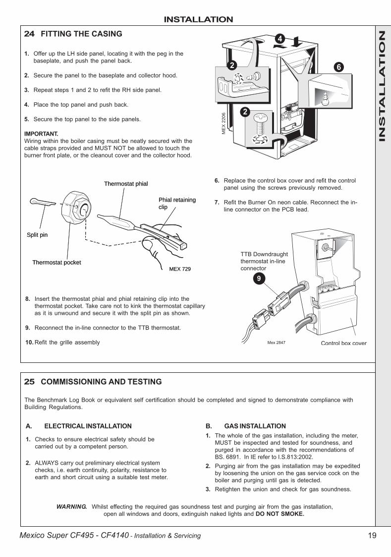
24 FITTING THE CASING
25 COMMISSIONING AND TESTING
A. ELECTRICAL INSTALLATION
1. Checks to ensure electrical safety should becarried out by a competent person.
2. ALWAYS carry out preliminary electrical systemchecks, i.e. earth continuity, polarity, resistance toearth and short circuit using a suitable test meter.
B. GAS INSTALLATION1. The whole of the gas installation, including the meter,
MUST be inspected and tested for soundness, andpurged in accordance with the recommendations ofBS. 6891. In IE refer to I.S.813:2002.
2. Purging air from the gas installation may be expeditedby loosening the union on the gas service cock on theboiler and purging until gas is detected.
3. Retighten the union and check for gas soundness.
Thermostat phial
Thermostat pocket
Phial retaining
clip
Split pin
MEX 729
1. Offer up the LH side panel, locating it with the peg in thebaseplate, and push the panel back.
2. Secure the panel to the baseplate and collector hood.
3. Repeat steps 1 and 2 to refit the RH side panel.
4. Place the top panel and push back.
5. Secure the top panel to the side panels.
IMPORTANT.Wiring within the boiler casing must be neatly secured with thecable straps provided and MUST NOT be allowed to touch theburner front plate, or the cleanout cover and the collector hood.
6. Replace the control box cover and refit the controlpanel using the screws previously removed.
7. Refit the Burner On neon cable. Reconnect the in-line connector on the PCB lead.
ME
X 2
20
6
8. Insert the thermostat phial and phial retaining clip into thethermostat pocket. Take care not to kink the thermostat capillaryas it is unwound and secure it with the split pin as shown.
9. Reconnect the in-line connector to the TTB thermostat.
10. Refit the grille assembly
The Benchmark Log Book or equivalent self certification should be completed and signed to demonstrate compliance withBuilding Regulations.
Thermostat phial
Thermostat pocket
Phial retaining
clip
Split pin
MEX 729
INS
TA
LL
AT
ION
200944-1.p65 3/8/2004, 3:41 PM19

INSTALLATION
20 Mexico Super CF495 - CF4140 - Installation & Servicing
26 INITIAL LIGHTING
LEGENDA Gas control valveB Burner pressure test pointC Main burner pressure adjuster
D Inlet pressure test pointE Gas service cockF Sightglass
��� ����
G Boiler thermostat knobH Burner On neon.J Overheat thermostat (optional) reset button.
TO LIGHT THE BOILER
1. Check that all the drain cocks are closed and any valves inthe flow and return are open.
2. Check that the gas service cock (E) is OPEN and the boilermains on/off switch is OFF.
3. Slacken the screw in the burner pressure test point (B) andconnect a gas pressure gauge via a flexible tube.
4. Switch the electricity supply ON and check that all externalcontrols are calling for heat.
5. Set the boiler thermostat knob (G) to position 6. The pilotsolenoid valve will open and the intermittent sparkcommence, continuing until the pilot is established. Themain burner will then cross-light smoothly. If this sequencedoes not occur, refer to the Fault Finding section.
6. Test for gas soundness around ALL boiler gas componentsusing leak detection fluid.
7. Operate the boiler for 10 minutes to stabilise the burnertemperature.
8. The boiler is preset at the factory to its nominal rating. If theburner setting pressure requires adjustment remove thesealing cap and turn the adjusting screw clockwise toincrease/anticlockwise to decrease the pressure until therequired burner pressure is achieved. Refer to Table 2,page 2. Refit the sealing cap.
9. Immmediately check that there is no spillage of combustionproducts from the draught diverter outlets by carrying out aspillage test, as detailed in BS.5440-1:2000.Note. This must be done before any building in.
10. Set the boiler mains on/off switch to OFF.
11. Remove the pressure gauge and tube. Retighten thesealing screw in the pressure test point.
12. Turn ON and check for gas soundness at the pressuretest point.
INS
TA
LL
AT
ION
200944-1.p65 3/8/2004, 3:41 PM20
INSTALLATION
21Mexico Super CF495 - CF4140 - Installation & Servicing
27 GENERAL CHECKS
Make the following checks for correct operation:
1. Turn the boiler thermostat OFF and ON to check that themain burner is extinguished and relit in response.
2. Set the boiler thermostat knob to position 6 and operate themains on/off switch. Check that the main burner lights andextinguishes in response.
3. Check that the programmer, if fitted, and all other systemcontrols function correctly.
Operate each control separately and check that the mainburner or circulating pump (as the case may be) responds.
4. Water circulation System
a. With the system HOT, examine all water connections forsoundness.
b. With the system still hot, turn off the gas, water andelectricity supplies to the boiler and drain down, in orderto complete the flushing process.
c. Refill and vent the system, clear all air locks and againcheck for water soundness.
d. Balance the system.
5. Finally, set the controls to the user's requirements, refit thelower front panel and close the controls door.
1. Hand the User's Instructions to the householder andexplain his or her responsibilities under the current GasSafety (Installation and Use) Regulations or rules in force.
2. Draw attention to the lighting instruction label affixed to theinside of the controls door.
3. Explain and demonstrate the lighting and shutting downprocedures, including the function of the TTB downdraughtthermostat.
4. The operation of the boiler and the use and adjustment ofALL system controls should be fully explained to thehouseholder, to ensure the greatest possible fuel economyconsistent with household requirements of both heatingand hot water consumption.
Advise the User of the precautions necessary to preventdamage to the system and to the building, in the event ofthe system remaining inoperative during frosty conditions.
Notes.
a. If an optional Programmer Kit is fitted refer to theseparate Programmer Kit Installation Instructionsand User's Instructions.
b. The temperatures quoted below are approximateand vary between installations.
28 HANDING OVER
After completing the installation and commissioning of the boiler systemthe installer should hand over to the householder by the following actions:
5. Explain the function and the use of the boiler thermostatand external controls.
6. Explain and demonstrate the function of time andtemperature controls, radiator valves etc., for theeconomic use of the system.
7. If an optional Programmer Kit is fitted then draw attentionto the Programmer User's Instructions and hand them tothe householder.
8. After installation, commissioning and customer hand-over please complete the appliance log bookand leave this with the customer. For IE, it is necessaryto complete a "Declaration of Conformity" to indicatecompliance to I.S. 813:2002.
9. Stress the importance of regular servicing by a CORGIregistered installer and that a comprehensive serviceshould be carried out AT LEAST ONCE A YEAR. In IEservicing work must be carried out by a CompetentPerson.
WARNING. The boiler must not be operated with the casing removed
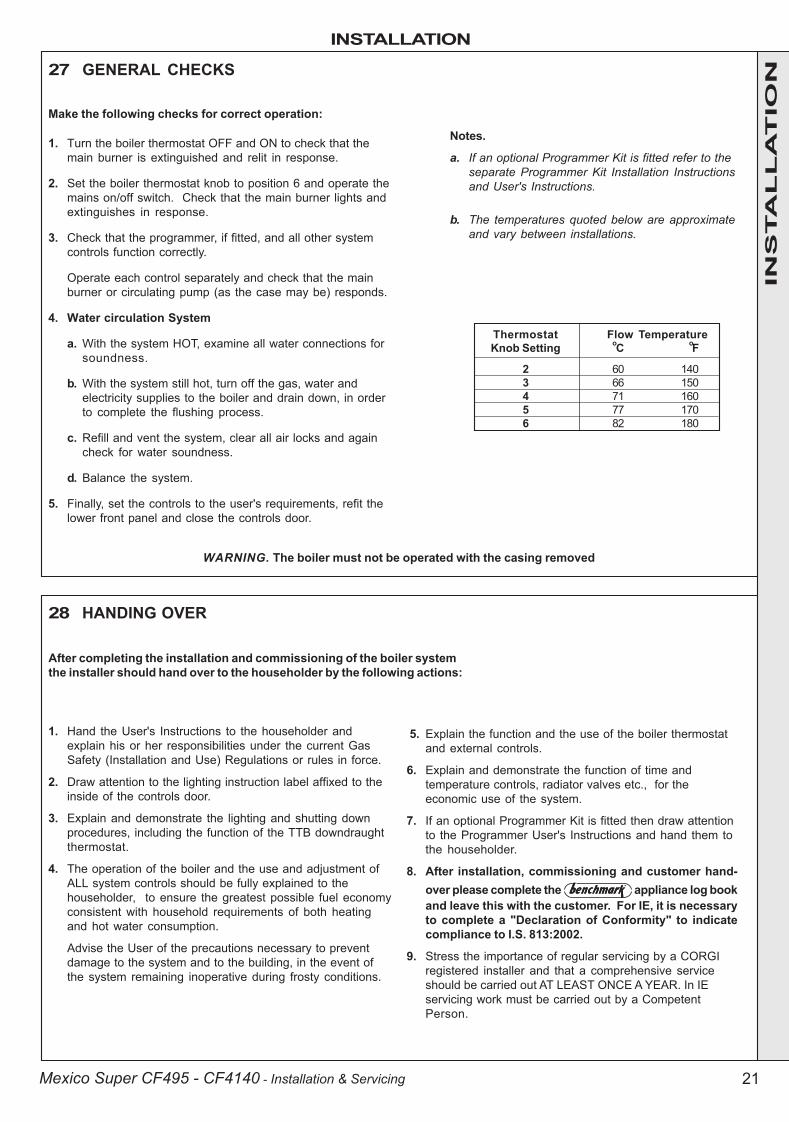
Thermostat Flow TemperatureKnob Setting oC oF
2 60 1403 66 1504 71 1605 77 1706 82 180
INS
TA
LL
AT
ION
200944-1.p65 3/8/2004, 3:41 PM21
SERVICING
22 Mexico Super CF495 - CF4140 - Installation & Servicing
29 SCHEDULETo ensure the continued safe and efficient operation of theappliance, it is recommended that it is checked at regularintervals and serviced as necessary. The frequency ofservicing will depend upon the installation condition andusage but should be carried out at least annually.
It is the law that any service work must be carried out by aCORGI registered installer. In IE servicing work must becarried out by a Competent Person.
a. Light the boiler and carry out a pre-service check,noting any operational faults.
b. Clean the main burners and lint gauzes.
c. Clean the lower front panel lint gauze.
d. Clean the heat exchanger.
e. Clean the main injectors.
f. Check that the flue is unobstructed and that the fluesystem, including the flue cleanout cover, is sealedcorrectly.
g. If the appliance has been installed in a compartment,check that the ventilation areas are clear.
The servicing procedures are covered more fully in Frames28-35 and MUST BE CARRIED OUT IN SEQUENCE.
WARNING. Always turn OFF the gas supply at the gasservice cock and switch OFF and DISCONNECT the electricalsupply to the appliance BEFORE SERVICING.
IMPORTANT. After completing the servicing or exchange ofcomponents always test for gas soundness, carry outfunctional checks as appropriate and test for spillage. Referto Frame 26. Note. It may be necessary to remove the boilercasing to carry out the spillage test.
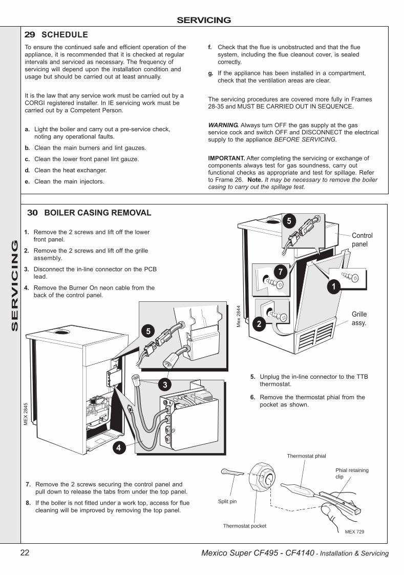
30 BOILER CASING REMOVAL
Thermostat phial
Thermostat pocket
Phial retaining
clip
Split pin
MEX 729
1. Remove the 2 screws and lift off the lowerfront panel.
2. Remove the 2 screws and lift off the grilleassembly.
3. Disconnect the in-line connector on the PCBlead.
4. Remove the Burner On neon cable from theback of the control panel.
7. Remove the 2 screws securing the control panel andpull down to release the tabs from under the top panel.
8. If the boiler is not fitted under a work top, access for fluecleaning will be improved by removing the top panel.
5. Unplug the in-line connector to the TTBthermostat.
6. Remove the thermostat phial from thepocket as shown.
SE
RV
ICIN
G
200944-1.p65 3/8/2004, 3:41 PM22

SERVICING
23Mexico Super CF495 - CF4140 - Installation & Servicing
31 BURNER AND CONTROLS ASSEMBLY REMOVAL
5. Inspect the pilot burner and ignition electrode -ensure that they are clear and in good condition.
Check that:
a. The pilot burner is clean and unobstructed.
b. The ignition electrode is clean and undamaged.
c. The ignition lead is in good condition and securelyconnected.
d. The spark gap is correct. Refer to Frame 44.
6. Clean or renew components as necessary.
32 LINT GAUZE REMOVAL
33 CLEANING THE BURNER ASSEMBLY
Gas service
union nutCombustion
chamber
Wing nuts
ME
X 2
143
1. Remove the 2 screws and lift off thefront panel and remove the grilleassembly from the casing. Refer toFrame 30.
2. Disconnect the electrical leads from thegas valve.
3. Disconnect the ignition lead from thePCB.
4. Remove the manifold nuts to removeboth burners from the burner front plate/ manifold assembly.
5. From each burner remove the 2 air boxsecuring nuts and CAREFULLY removethe air box and venturi arrangement.
6. Withdraw both lint gauzes.
1. Remove the 2 screws and lift off the frontpanel and remove the grille assembly fromthe casing.
2. Disconnect theelectrical leads fromthe gas valve.
3. Disconnect theignition lead from thePCB.
4. Undo the gasservice cock unionnut.
5. Remove the 4 wingnuts and withdrawthe burner andcontrols assembly,complete, from theboiler.
ME
X 2
21
0
1. Clean the lint gauze(s) to remove any deposits of lint, fluffetc.
2. Brush off any deposits that may have fallen on to theburner head, ensuring that the flame ports areunobstructed, and remove any debris that may havecollected.Note. Brushes with metallic bristles MUST NOT be used.
3. Remove the main burner injectors. Check, clean orreplace, as required.
4. Refit the injectors, using an approved jointing compound.
���
����
SE
RV
ICIN
G
200944-1.p65 3/8/2004, 3:41 PM23

SERVICING
24 Mexico Super CF495 - CF4140 - Installation & Servicing
34 CLEANING THE LOWER FRONT PANEL LINT ARRESTING GAUZE
1. Unclip the gauze from the grille assembly andlift it clear of the bottom return edge.
2. Clean the gauze to remove any deposits of lintor fluff.
3. Refit the gauze by entering the bottom edgebehind the grille return edge and engaging thetop in the clips.
1. Remove the 2 wing nuts and lift off the cleanout cover.
2. Lift out the flue baffles.
3. Remove all loose deposits from the heat exchanger,especially from between the fins, using a suitablebrush. Remove all debris from the combustion chamberbase.
4. Check that the flue outlet duct is unobstructed.
35 CLEANING THE FLUEWAYS 36 REASSEMBLY
37 GAS PRESSURE ADJUSTMENT
MEX 2205
Baffles
�������� ���
Reassemble the boiler in the following order :
1. Refit the flue baffles into the boiler flueways, ensuringthat they are correctly repositioned. Refer to Frame 10.
2. Refit the flue cleanout cover, renewing any damaged ordeteriorating sealing gasket.
3. Refit the casing top panel.
4. Reconnect the electrical wiring ensuring the TTBthermostat is connected. Refit the controls panel,ensuring that the thermostat phial and phial retainingclip are correctly located in the thermostat pocket andsecured by the split pin. Refer to Frame 30.
5. Check the sightglass in the front plate - clean or renewas necessary.
6. Renew any damaged or deteriorating front plategasket.
7. Refit the burner and controls assembly.
8. Reconnect the gas service cock.
9. Refit the grille assembly.
1. Pilot PressurePilot adjustment is factory set to maximum and noadjustment is possible,
2. Main Burner PressureAfter servicing, reference should be made to Table 2,page 2, which quotes details of the output with the burnerpressure and heat input.
Any required adjustments should be made using thepressure adjustment screw. Refer to Frame 26, 'InitialLighting'.
Refit the lower front panel in reverse order.
SE
RV
ICIN
G
200944-1.p65 3/8/2004, 3:41 PM24

SERVICING
25Mexico Super CF495 - CF4140 - Installation & Servicing
38 GENERAL
40 PILOT BURNER REPLACEMENT
REPLACEMENT OF PARTS
1. Refer to Frame 38.
2. Undo the 2 screws, lift off the front panel and remove thegrille assembly. Refer to Frame 30.
3. Disconnect the electrical leads from the gas valve.
4. Disconnect the ignition lead from the PCB.
5. Undo the gas cock union. Remove the 4 wing nuts andwithdraw the burner and controls assembly, complete, fromthe boiler.
6. Undo the pilot supply pipe connection and ease clear of thepilot burner. DO NOT LOSE the pilot injector, which is apush-fit in the pilot burner housing.
7. Remove the 2 securing screws and washers, and withdrawthe pilot burner.
8. Fit the new pilot burner and reassemble in reverse order,ensuring that:
a. The injector is in position when refitting the pilot supply.b. A gas-tight joint is made.c. The spark gap is correct. Refer to Frame 45.
When replacing any component:
1. Isolate the electricity supply.
2. Remove the lower front panel and grilleassembly.
3. Turn off the gas supply at the boiler.
Note. In order to assist fault finding, the control box PCB is fittedwith 2 indicator lights which represent the following boiler conditions:
Neon I3 Mains electricity ON.
Neon SG1 Flashes to indicate ignition operation (stops afterdetection.)
For replacement of programmer units refer to the separateProgrammer Kit instructions.
The boiler MUST NOT be operated if the casing is not fitted.
39 SIGHTGLASS REPLACEMENT
1. Refer to Frame 38.
2. Unfasten the 2 M5 hexagon nuts and washers.Remove the assembly from the front plate.
3. Fit the new sightglass and reassemble, as shown.
4. Retighten the 2 M5 hexagon nuts to ensure anairtight seal. Do NOT overtighten.
SE
RV
ICIN
G
200944-1.p65 3/8/2004, 3:41 PM25

SERVICING
26 Mexico Super CF495 - CF4140 - Installation & Servicing
41 CONTROL THERMOSTAT REPLACEMENT
42 CONTROL PANEL REPLACEMENT
1. Refer to Frame 38.
2. Remove 2 screws and lift off the front lower panel.Refer to Frame 30.
3. Disconnect the in-line connector on the PCBlead.
4. Remove the Burner On neon cable fromthe back of the control panel.
5. Pull off the thermostat knob.
6. Remove the 2 screws and pull down the controlpanel tabs clear of the top panel.
7. Remove the thermostat phial from the pocket. Referto Frame 30.
8. Remove the bottom screw and remove thecover.
9. Remove the top screw and ease the controlbox off the control panel.
10. Remove the 2 screws to release thethermostat bracket.
11. Disconnect the electrical leads.
12. Unscrew the thermostat nut to withdraw thethermostat.
13. Fit the new thermostat and reassemble in reverse order.
1. Refer to Frame 38.
2. Remove the 2 screws and lift off thelower front panel. Refer to Frame 30.
3. Pull off the thermostat knob.
4. Disconnect the in-line connector on thePCB lead.
5. Remove the Burner On neon cablefrom the back of the control panel.
6. Unscrew the 2 screws and pull downthe control panel so that the 2 tabsclear the top panel.
7. Remove the thermostat phial from thepocket. Refer to Frame 30.
8. Remove the bottom screw and removethe cover from the control box.
9. Remove the top screw and ease thecontrol box off the control panel.
10. Disconnect the mains electrical supplyfrom the terminal strip and releasefrom its clamp.
11. Remove the 2 screws to release thethermostat bracket.
12. Unplug the in-line connector to the TTB thermostat.
13. On the new control box gain access to the control thermostatas described above.
14. Reconnect the TTB thermostat lead to the controlthermostat and terminal strip marked 'LG'.
15. Assemble new control box and panel and fit to thecasing in reverse order.
SE
RV
ICIN
G
200944-1.p65 3/8/2004, 3:41 PM26
SERVICING
27Mexico Super CF495 - CF4140 - Installation & Servicing
Thermostat
Hook plate
Sensor endMex 1861
�
�������
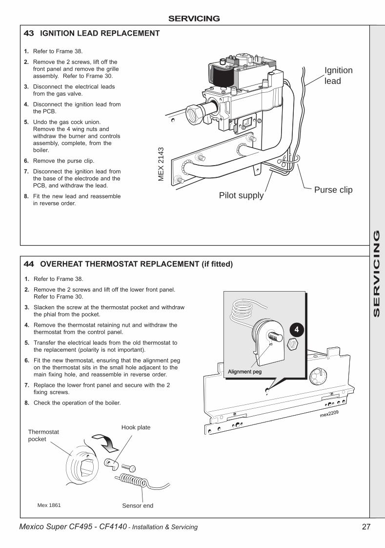
43 IGNITION LEAD REPLACEMENT
Ignition
lead
Pilot supply
ME
X 2
14
3
Purse clip
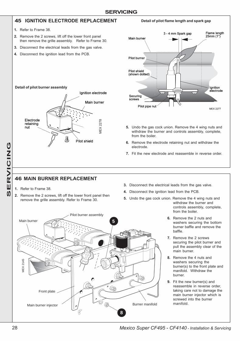
44 OVERHEAT THERMOSTAT REPLACEMENT (if fitted)
1. Refer to Frame 38.
2. Remove the 2 screws, lift off thefront panel and remove the grilleassembly. Refer to Frame 30.
3. Disconnect the electrical leadsfrom the gas valve.
4. Disconnect the ignition lead fromthe PCB.
5. Undo the gas cock union.Remove the 4 wing nuts andwithdraw the burner and controlsassembly, complete, from theboiler.
6. Remove the purse clip.
7. Disconnect the ignition lead fromthe base of the electrode and thePCB, and withdraw the lead.
8. Fit the new lead and reassemblein reverse order.
1. Refer to Frame 38.
2. Remove the 2 screws and lift off the lower front panel.Refer to Frame 30.
3. Slacken the screw at the thermostat pocket and withdrawthe phial from the pocket.
4. Remove the thermostat retaining nut and withdraw thethermostat from the control panel.
5. Transfer the electrical leads from the old thermostat tothe replacement (polarity is not important).
6. Fit the new thermostat, ensuring that the alignment pegon the thermostat sits in the small hole adjacent to themain fixing hole, and reassemble in reverse order.
7. Replace the lower front panel and secure with the 2fixing screws.
8. Check the operation of the boiler.
SE
RV
ICIN
G
200944-1.p65 3/8/2004, 3:41 PM27
SERVICING
28 Mexico Super CF495 - CF4140 - Installation & Servicing
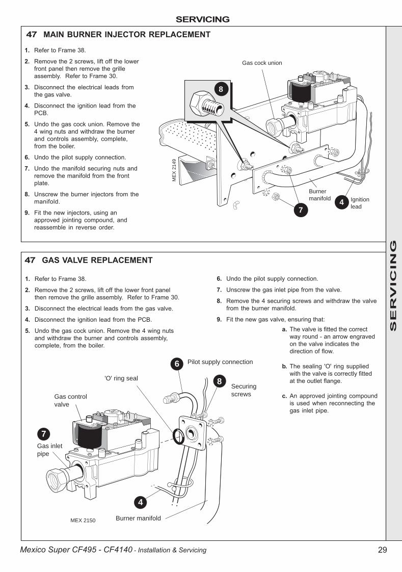
46 MAIN BURNER REPLACEMENT
1. Refer to Frame 38.
2. Remove the 2 screws, lift off the lower front panel thenremove the grille assembly. Refer to Frame 30.
Front plate
Main burner
Burner manifold
ME
X 2
145
Pilot burner assembly
Main burner injector
5
8
45 IGNITION ELECTRODE REPLACEMENT
Detail of pilot burner assembly
�������
Detail of pilot flame length and spark gap
3. Disconnect the electrical leads from the gas valve.
4. Disconnect the ignition lead from the PCB.
5. Undo the gas cock union. Remove the 4 wing nuts and
��� ����
withdraw the burner andcontrols assembly, complete,from the boiler.
6. Remove the 2 nuts andwashers securing the bottomburner baffle and remove thebaffle.
7. Remove the 2 screwssecuring the pilot burner andpull the assembly clear of themain burner.
8. Remove the 4 nuts andwashers securing theburner(s) to the front plate andmanifold. Withdraw theburner.
9. Fit the new burner(s) andreassemble in reverse order,taking care not to damage themain burner injector which isscrewed into the burnermanifold.
1. Refer to Frame 38.
2. Remove the 2 screws, lift off the lower front panelthen remove the grille assembly. Refer to Frame 30.
3. Disconnect the electrical leads from the gas valve.
4. Disconnect the ignition lead from the PCB.
5. Undo the gas cock union. Remove the 4 wing nuts andwithdraw the burner and controls assembly, complete,from the boiler.
6. Remove the electrode retaining nut and withdraw theelectrode.
7. Fit the new electrode and reassemble in reverse order.
SE
RV
ICIN
G
200944-1.p65 3/8/2004, 3:41 PM28
SERVICING
29Mexico Super CF495 - CF4140 - Installation & Servicing
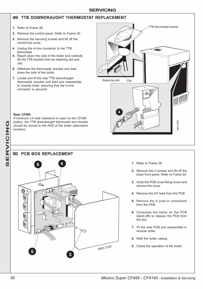
47 MAIN BURNER INJECTOR REPLACEMENT
8
Burner
manifold
ME
X 2
14
9
Gas cock union
74 Ignition
lead
1. Refer to Frame 38.
2. Remove the 2 screws, lift off the lowerfront panel then remove the grilleassembly. Refer to Frame 30.
3. Disconnect the electrical leads fromthe gas valve.
4. Disconnect the ignition lead from thePCB.
5. Undo the gas cock union. Remove the4 wing nuts and withdraw the burnerand controls assembly, complete,from the boiler.
6. Undo the pilot supply connection.
7. Undo the manifold securing nuts andremove the manifold from the frontplate.
8. Unscrew the burner injectors from themanifold.
9. Fit the new injectors, using anapproved jointing compound, andreassemble in reverse order.
47 GAS VALVE REPLACEMENT
Gas control
valve
Gas inlet
pipe
Pilot supply connection
MEX 2150 Burner manifold
6
7
4
8'O' ring seal
Securing
screws
1. Refer to Frame 38.
2. Remove the 2 screws, lift off the lower front panelthen remove the grille assembly. Refer to Frame 30.
3. Disconnect the electrical leads from the gas valve.
4. Disconnect the ignition lead from the PCB.
5. Undo the gas cock union. Remove the 4 wing nutsand withdraw the burner and controls assembly,complete, from the boiler.
6. Undo the pilot supply connection.
7. Unscrew the gas inlet pipe from the valve.
8. Remove the 4 securing screws and withdraw the valvefrom the burner manifold.
9. Fit the new gas valve, ensuring that:a. The valve is fitted the correct
way round - an arrow engravedon the valve indicates thedirection of flow.
b. The sealing 'O' ring suppliedwith the valve is correctly fittedat the outlet flange.
c. An approved jointing compoundis used when reconnecting thegas inlet pipe.
SE
RV
ICIN
G
200944-1.p65 3/8/2004, 3:41 PM29
SERVICING
30 Mexico Super CF495 - CF4140 - Installation & Servicing
49 TTB DOWNDRAUGHT THERMOSTAT REPLACEMENT
Note. CF495If minimum LH side clearance is used on the CF495boilers, the TTB downdraught thermostat and bracketshould be moved to the RHS of the boiler (alternativelocation).
MEX 2156
6 4
35
50 PCB BOX REPLACEMENT
1. Refer to Frame 38.
2. Remove the control panel. Refer to Frame 30.
3. Remove the securing screws and lift off thecontrol box cover.
4. Unplug the in-line connector to the TTBthermostat .
5. Reach down the side of the boiler and carefullylift the TTB bracket from its retaining slot andclip.
6. Withdraw the thermostat, bracket and leaddown the side of the boiler.
7. Locate and fit the new TTB downdraughtthermostat, bracket and lead and reassemblein reverse order, ensuring that the in-lineconnector is secured.
1. Refer to Frame 38.
2. Remove the 2 screws and lift off thelower front panel. Refer to Frame 30.
3. Undo the PCB cover fixing screw andremove the cover.
4. Remove the HT lead from the PCB
5. Remove the 6 push-in connectorsfrom the PCB.
6. Compress the barbs on the PCBstand-offs to release the PCB fromthe box
7. Fit the new PCB and reassemble inreverse order.
8. Refit the boiler casing.
9. Check the operation of the boiler.
SE
RV
ICIN
G
200944-1.p65 3/8/2004, 3:41 PM30

FAULT FINDING
FA
ULT
FIN
DIN
G F
AU
LT
FIN
DIN
G F
AU
LT
FIN
DIN
G F
AU
LT
FIN
DIN
G
31Mexico Super CF495 - CF4140 - Installation & Servicing
Detailed instructions on the cleaning and adjustment orreplacement of faulty components are contained in the'Servicing' section of this publication.
Before attempting any electrical fault finding ALWAYS carryout preliminary electrical system checks, i.e. earth continuity,polarity and resistance to earth using a suitable meter.
Check mains neon on PCB.Is it illuminated?
YES
NO
Is there a live supply toboth terminals of overheat'stat? (If no overheat 'stat
fitted go to next step).
YES
NO
Check the control 'stat isset to max and mains
switch is on.Is there a regular sparkfrom tube SG1 on the
PCB?
Check mains supply and fuses. Check controls are calling for heat. Checkboiler wiring connections are OK. Check if the TTB downdraught thermostat has
operated in adverse wind conditions.
NOCan the overheat thermostat
be reset with the system cold?
Replace fuse but before restoring power check for short circuitbetween L/N and L/Earth on all components plugged into the PCB.
Check gap at ignition electrode. Check electrode and leads are not damaged.Check the lead is not shorting to earth. Rectify as necessary.
Replace the overheat 'stat.
Has the fuse on the PCB blown?
Reset the overheat 'stat. Set control'stat to maximum. Allow the boiler to
reach temperature - if the overheat 'stattrips again, measure flow temperature.
If above 90°C replace control 'stat.If below 90°C replace overheat 'stat.
YES
Is there a spark at theignition electrode?
Does the pilot burner light?NOIs there a gas supply to the boiler &
has the gas supply been purged of air?Connect or rectify and
purge the system of air.
NO
YES
Replace the PCB.
NO YES
NO
YES
NO
YES
NO
YES
NO
Ensure pilot and main gas valve leads are not crossedover. Is there a supply voltage at the pilot gas valve?
Is the pilot injectorblocked or the pilot
supply pipe damaged? Rectify or replace as necessary
Check connections at the gasvalve and rectify as necessary.
If no connection fault foundreplace PCB.
Replace gas valve
YES
Does the spark stopafter the pilot is lit?
YES
Does the main burnercross-light from the pilot?
NOCheck polarity of mains supply. Check
continuity of ignition lead.Does spark now stop when pilot is lit?
Is there a supply voltage at the main gas valve?
Check connectionsto PCB.
If no fault changePCB.
Is the main injector blocked? Replace main gas solenoid valve.Does the main burner light?
YES
NO
YES
Clear blockage and refit.Does main burner light?
YES
NO
Replacegasvalve
YES
NO
YES
NO
Boileroperating
satisfactorilyCheck for correct gas
supply pressure.Rectify as necessary.
NOYES
YES
NO
YES NO
200944-1.p65 3/8/2004, 3:42 PM31
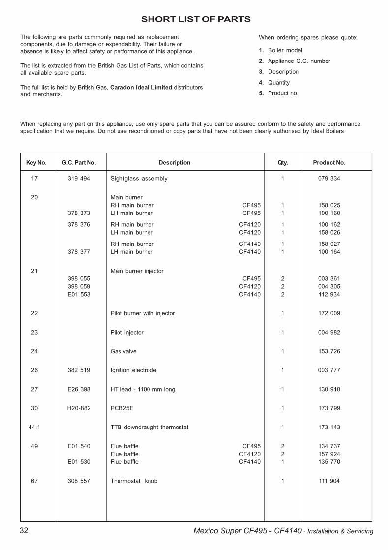
SHORT LIST OF PARTS
32 Mexico Super CF495 - CF4140 - Installation & Servicing
Key No. G.C. Part No. Description Qty. Product No.
17 319 494 Sightglass assembly 1 079 334
20 Main burnerRH main burner CF495 1 158 025
378 373 LH main burner CF495 1 100 160
378 376 RH main burner CF4120 1 100 162LH main burner CF4120 1 158 026
RH main burner CF4140 1 158 027378 377 LH main burner CF4140 1 100 164
21 Main burner injector398 055 CF495 2 003 361398 059 CF4120 2 004 305E01 553 CF4140 2 112 934
22 Pilot burner with injector 1 172 009
23 Pilot injector 1 004 982
24 Gas valve 1 153 726
26 382 519 Ignition electrode 1 003 777
27 E26 398 HT lead - 1100 mm long 1 130 918
30 H20-882 PCB25E 1 173 799
44.1 TTB downdraught thermostat 1 173 143
49 E01 540 Flue baffle CF495 2 134 737Flue baffle CF4120 2 157 924
E01 530 Flue baffle CF4140 1 135 770
67 308 557 Thermostat knob 1 111 904
The following are parts commonly required as replacementcomponents, due to damage or expendability. Their failure orabsence is likely to affect safety or performance of this appliance.
The list is extracted from the British Gas List of Parts, which containsall available spare parts.
The full list is held by British Gas, Caradon Ideal Limited distributorsand merchants.
When ordering spares please quote:
1. Boiler model
2. Appliance G.C. number
3. Description
4. Quantity
5. Product no.
When replacing any part on this appliance, use only spare parts that you can be assured conform to the safety and performancespecification that we require. Do not use reconditioned or copy parts that have not been clearly authorised by Ideal Boilers
200944-2.pmd 6/2/2004, 8:37 AM32
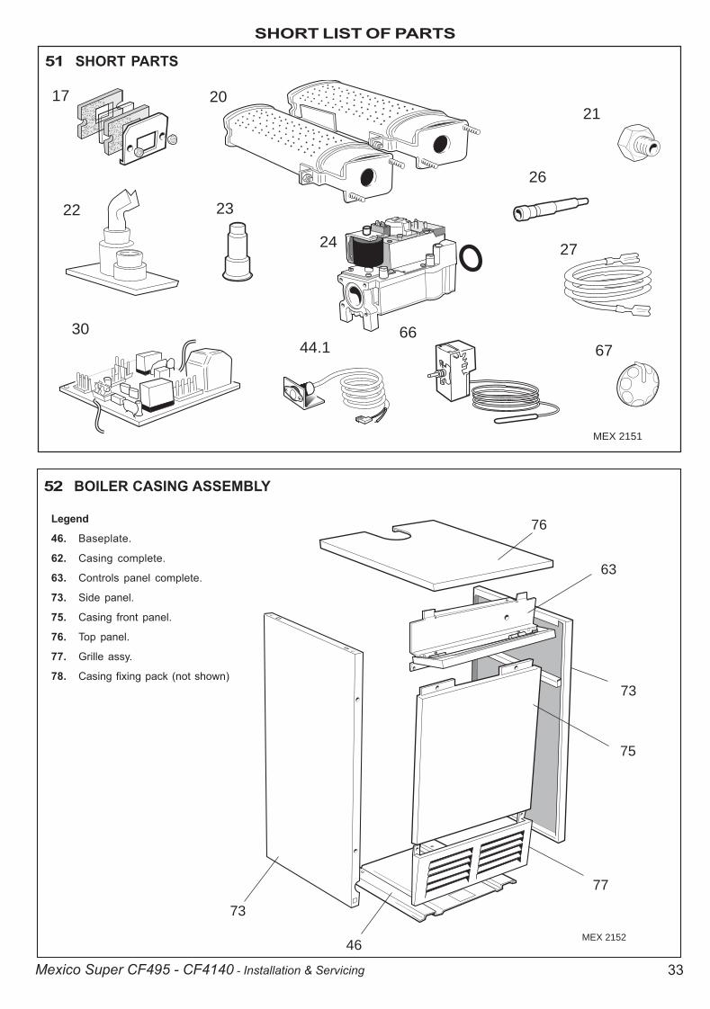
SHORT LIST OF PARTS
33Mexico Super CF495 - CF4140 - Installation & Servicing
51 SHORT PARTS
MEX 2151
17 20
22 23
30
26
21
2724
6766
44.1
52 BOILER CASING ASSEMBLY
MEX 2152
76
63
73
75
77
46
73
Legend
46. Baseplate.
62. Casing complete.
63. Controls panel complete.
73. Side panel.
75. Casing front panel.
76. Top panel.
77. Grille assy.
78. Casing fixing pack (not shown)
200944-1.p65 3/8/2004, 3:42 PM33

LIST OF PARTS
34 Mexico Super CF495 - CF4140 - Installation & Servicing
ME
X 2
154
22
20
16
21
28 2425
18
17
19
26
27
54 BURNER AND CONTROLS ASSEMBLY - Exploded View
Legend
16. Front plate.
17. Sightglass.
18. Burner manifold.
19 Pilot pipe.
20. Burner.
21. Burner injector - 2 off.
22. Pilot burner.
24. Gas valve.
25. 'O' ring.
26. Ignition electrode.
27. Ignition lead.
28. Gas service cock.
Legend
63. Controls panel complete
65. Control box.
66. Boiler control thermostat.
67. Thermostat knob.
64. Control panel.
72. Magnetic strip.
71. Controls front panel.
53 BOILER CONTROL PANEL - Exploded View
200944-1.p65 3/8/2004, 3:42 PM34
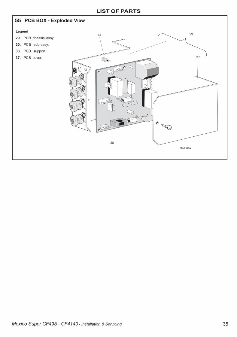
LIST OF PARTS
35Mexico Super CF495 - CF4140 - Installation & Servicing
55 PCB BOX - Exploded View
Legend
29. PCB chassis assy.
30. PCB sub-assy.
33. PCB support.
37. PCB cover.
33 29
30
37
MEX 2155
200944-1.p65 3/8/2004, 3:42 PM35

Ideal Boilers, P.O. Box 103, National Ave, Kingston upon Hull,HU5 4JN. Telephone: 01482 492 251 Fax: 01482 448 858.Registration No. London 322 137.
Technical Training
Caradon Ideal Limited pursues a policy of continuingimprovement in the design and performance of its products. Theright is therefore reserved to vary specification without notice.
The Ideal Boilers Technical Training Centre offers a seriesof first class training courses for domestic, commercial andindustrial heating installers, engineers and systemspecifiers.For details of courses please ring: ............ 01482 498 432
THIS SYMBOL IS YOURASSURANCE OF QUALITY
These appliances are designed for use with Natural Gasonly. They have been tested and conform with theprovisions of BS. 6332 and BS. 5258.
CERTIFIED PRODUCTManufactured under a BS EN ISO 9001: 2000Quality System accepted by BSI
The code of practice for the installation,commissioning & servicing of central heating systems
Ideal Installer/Technical Helpline: 01482 498663www.idealboilers.com
200944-1.p65 3/8/2004, 3:42 PM36