mfc 400mfc 400mfc 400mfc 400 - cdn.krohne.com
TRANSCRIPT
Signal converter for mass flowmeters
Description of Modbus interfaceDescription of Modbus interfaceDescription of Modbus interfaceDescription of Modbus interface
Electronic Revision: ER 1.0.x
MFC 400MFC 400MFC 400MFC 400 Supplementary InstructionsSupplementary InstructionsSupplementary InstructionsSupplementary Instructions
© KROHNE 05/2018 - 4002525103 - AD Modbus MFC400 ER1.0 R03 en
CONTENTS
2 www.krohne.com 05/2018 - 4002525103 - AD Modbus MFC400 ER1.0 R03 en
MFC 400
1 General information 4
1.1 Scope of the document..................................................................................................... 41.2 Scope of delivery............................................................................................................... 41.3 Modbus protocol interface ............................................................................................... 4
2 Technical data 5
2.1 General technical data ..................................................................................................... 52.2 Technical data of the Modbus interface (according to EIA/TIA standards) ..................... 5
3 Electrical connections 6
3.1 Modbus connection........................................................................................................... 63.2 Connection to Modbus bus ............................................................................................... 6
4 Establish RS485 connection 7
5 Modbus protocol 8
5.1 RTU frame format............................................................................................................. 85.2 Data representation ......................................................................................................... 9
5.2.1 8-bit values.............................................................................................................................. 95.2.2 16-bit values............................................................................................................................ 95.2.3 32-bit values............................................................................................................................ 95.2.4 64-bit values.......................................................................................................................... 10
5.3 Modbus Register Addresses .......................................................................................... 115.4 Supported Function Codes ............................................................................................. 115.5 Error messages.............................................................................................................. 115.6 Device identification ....................................................................................................... 125.7 Diagnostics ..................................................................................................................... 135.8 Parameters..................................................................................................................... 13
5.8.1 Device Control....................................................................................................................... 145.8.2 Device Status......................................................................................................................... 155.8.3 Measurement values ............................................................................................................ 165.8.4 Measurement Status compliant with NAMUR NE 107 ......................................................... 165.8.5 Auxiliary Values..................................................................................................................... 175.8.6 Totaliser ................................................................................................................................ 175.8.7 Zero Calibration .................................................................................................................... 205.8.8 Density Calibration Coefficients ........................................................................................... 215.8.9 Density Configuration ........................................................................................................... 215.8.10 Filters .................................................................................................................................. 225.8.11 System Control.................................................................................................................... 225.8.12 Calibration Coefficients ...................................................................................................... 235.8.13 Modbus RS485 Communication Settings ........................................................................... 245.8.14 NAMUR NE 107 Variable Event Group(s) ............................................................................ 255.8.15 Concentration 1................................................................................................................... 265.8.16 Concentration 2................................................................................................................... 27
CONTENTS
3www.krohne.com05/2018 - 4002525103 - AD Modbus MFC400 ER1.0 R03 en
MFC 400
6 Application sequences 28
6.1 Saving and restoring the configuration setting ............................................................. 286.2 Zero calibration .............................................................................................................. 29
7 Troubleshooting 30
7.1 No response to Modbus requests .................................................................................. 307.2 Communication errors ................................................................................................... 307.3 Responding with exception "Illegal Function" ............................................................... 307.4 Responding with exception "Illegal Data Address" ....................................................... 317.5 Responding with exception "Illegal Data Value"............................................................ 31
8 Appendix 32
8.1 NAMUR NE 107 Event Group(s)...................................................................................... 328.2 NAMUR NE 107 status signals ....................................................................................... 338.3 Supported Modbus function codes................................................................................. 338.4 Number format............................................................................................................... 368.5 Glossary .......................................................................................................................... 36
9 Notes 37
1 GENERAL INFORMATION
4
MFC 400
www.krohne.com 05/2018 - 4002525103 - AD Modbus MFC400 ER1.0 R03 en
1.1 Scope of the document
These instructions are supplementary to the signal converter handbook. For all other data, use the relevant chapters of the handbook. If you do not have this document, please contact the nearest office or download them from the manufacturer's internet site.
1.2 Scope of delivery
The information in this supplementary manual only contains the data applicable to Modbus communication.
The technical data in the handbook shall be valid in its current version, provided that it is not rendered invalid or replaced by this supplement.
1.3 Modbus protocol interface
The Modbus interface to the signal converter is implemented in the Modbus RTU communications protocol and is done in accordance with the specification and requirements of the "Modbus Protocol Specification V1.1b".
The physical electrical parameters of the Modbus specification are defined by the EIA/TIA-485 (RS485) standard and the "Modbus over Serial Line - Specification and Implementation Guide V1.02".
Both specifications can be obtained on the official website of the Modbus organisation:http://www.modbus.org
TECHNICAL DATA 2
5
MFC 400
www.krohne.com05/2018 - 4002525103 - AD Modbus MFC400 ER1.0 R03 en
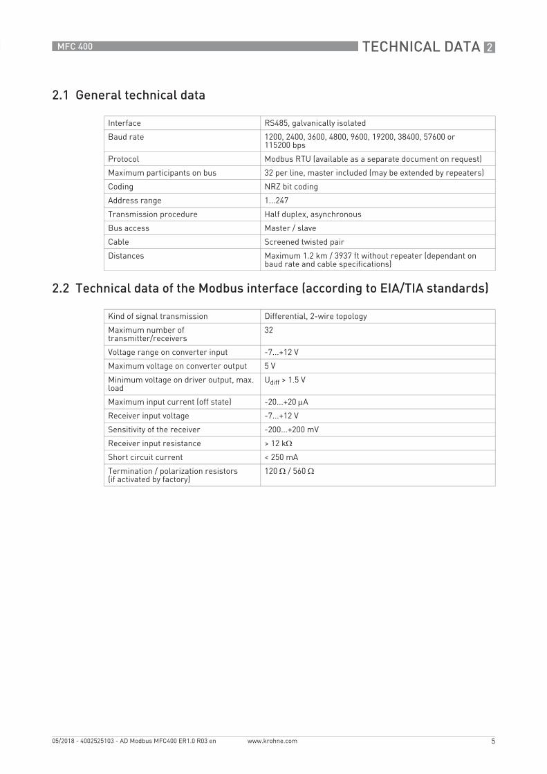
2.1 General technical data
2.2 Technical data of the Modbus interface (according to EIA/TIA standards)
Interface RS485, galvanically isolated
Baud rate 1200, 2400, 3600, 4800, 9600, 19200, 38400, 57600 or 115200 bps
Protocol Modbus RTU (available as a separate document on request)
Maximum participants on bus 32 per line, master included (may be extended by repeaters)
Coding NRZ bit coding
Address range 1...247
Transmission procedure Half duplex, asynchronous
Bus access Master / slave
Cable Screened twisted pair
Distances Maximum 1.2 km / 3937 ft without repeater (dependant on baud rate and cable specifications)
Kind of signal transmission Differential, 2-wire topology
Maximum number of transmitter/receivers
32
Voltage range on converter input -7...+12 V
Maximum voltage on converter output 5 V
Minimum voltage on driver output, max. load
Udiff > 1.5 V
Maximum input current (off state) -20...+20 μA
Receiver input voltage -7...+12 V
Sensitivity of the receiver -200...+200 mV
Receiver input resistance > 12 kΩ
Short circuit current < 250 mA
Termination / polarization resistors(if activated by factory)
120 Ω / 560 Ω

3 ELECTRICAL CONNECTIONS
6
MFC 400
www.krohne.com 05/2018 - 4002525103 - AD Modbus MFC400 ER1.0 R03 en
3.1 Modbus connection
The signal converter is hooked up onto the bus using terminals C and D:
Terminals A and B of the signal converter are dependant on the options selected at order.Refer to the standard handbook of the signal converter for connection details.
3.2 Connection to Modbus bus
The signal converter is designed to be connected as a slave device onto the 2-wire bus implementation of the Modbus serial physical layer definition.
In addition to the D0 and D1 signal lines the bus MUSTMUSTMUSTMUST include a "Common" signal line to act as a ground reference point for the data signals.
For proper operation of Modbus in half duplex mode in single or multi-drop communication, it is recommended that a termination resistor is applied to both ends of the data line. The simplest form of termination is line-to-line resistor across the differential input.
In RTU mode the Modus protocol requires quiet periods on the communications bus for synchronisation. It is therefore important that the Modbus is not allowed to "float", i.e. unreferenced to 0 V, as this could lead to spurious signals due to noise pick-up. It is therefore necessary to employ biasing resistors at one point on the bus network.
Terminals Description
D- Signal A (D 0)
D Signal B (D 1)
C- Common 0 V
C Not connected
ESTABLISH RS485 CONNECTION 4
7
MFC 400
www.krohne.com05/2018 - 4002525103 - AD Modbus MFC400 ER1.0 R03 en
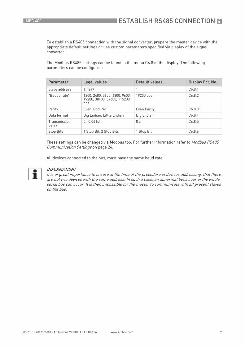
To establish a RS485 connection with the signal converter, prepare the master device with the appropriate default settings or use custom parameters specified via display of the signal converter.
The Modbus RS485 settings can be found in the menu C6.8 of the display. The following parameters can be configured:
These settings can be changed via Modbus too. For further information refer to Modbus RS485 Communication Settings on page 24.
All devices connected to the bus, must have the same baud rate.
Parameter Legal values Default values Display Fct. No.
Slave address 1...247 1 C6.8.1
"Baude rate" 1200, 2400, 3600, 4800, 9600, 19200, 38400, 57600, 115200 bps
19200 bps C6.8.2
Parity Even, Odd, No Even Parity C6.8.3
Data format Big Endian, Little Endian Big Endian C6.8.4
Transmission delay
0...0.04 [s] 0 s C6.8.5
Stop Bits 1 Stop Bit, 2 Stop Bits 1 Stop Bit C6.8.6
INFORMATION!It is of great importance to ensure at the time of the procedure of devices addressing, that there are not two devices with the same address. In such a case, an abnormal behaviour of the whole serial bus can occur. It is then impossible for the master to communicate with all present slaves on the bus.

5 MODBUS PROTOCOL
8
MFC 400
www.krohne.com 05/2018 - 4002525103 - AD Modbus MFC400 ER1.0 R03 en
5.1 RTU frame format
Using RTU (Remote Terminal Unit) format, data is transmitted as 8 bit binary characters. There are no special characters to determine the start and end of a message frame. Synchronization is achieved by a minimum silent period of at least 3.5 character times before the start of each frame transmission and a maximum silent period of 1.5 character times between characters in the same frame.
The format of the query and response frames vary slightly depending upon the function code. The basic form is outlined below.
Command function Frame format Description
Silent period 3.5 x T All transmissions must be preceded by a minimum silent period of 3.5 x T, where T is the transmission time of a single character. This can be calculated from the baud rate, e.g. T = 572 µs at 19.2 kbps.
Slave address 8 bits This is a single byte slave address which is transmitted first and must be in the range of 1...247. Address 0 is reserved for a broadcast address which all slaves should recognise, and therefore requires no response.
Function code 8 bits This is an eight bit code in the range of 1...255 although only 126 functions exist as the codes 129...255 represent an error condition. An error condition occurs when the addressed slave does not accept the command, in which case it responds with the function code + 128, i.e. with its msb set to 1.
Register start address or byte count when required
8 bit byte count16 bit address
Register start address:Register start address:Register start address:Register start address: for a query command that requires data to be returned, this field will contain the 16 bit start address of the register (or data) to be returned.Note that the signal converter uses protocol addresses. Therefore the register address listed is the actual number required in the Modbus command.
E.g:E.g:E.g:E.g: to access input register 30006, the register start address is 30006 = 0x7536.
Byte count:Byte count:Byte count:Byte count: In general this is only present in frames that are transferring data, and has a value equal to the number of bytes contained in the data field. The data field is limited to a maximum of 250 bytes.
Number of points or data bytes when required
n x 8 bits Number of points:Number of points:Number of points:Number of points: for a query command that requires data to be returned, this field will contain the number of registers to be returned regardless of their bit size.
Data bytes:Data bytes:Data bytes:Data bytes: contains the data requested. The signal converter can use Big Endian format (MSB first) or Little Endian format (LSB first).
CRC 16 bits This field contains a 16 bit CRC which is calculated on all the data bits of the message bytes.

MODBUS PROTOCOL 5
9
MFC 400
www.krohne.com05/2018 - 4002525103 - AD Modbus MFC400 ER1.0 R03 en
5.2 Data representation
There are two data types used to transmit information on a Modbus data bus, the "Bit" and the "Register". The "Bit" represents a single binary state, whether as an output or an input condition. The "Register" is a 16-bit integer transmitted as two 8-bit characters. Using multiple "Registers" the Modbus interface can transmit higher accuracy values such as "Floating Point" and "Double Precision Floating Point" numbers.
"Bit" variables are packed into a byte containing 8 bit, so each character, sent or received, can contain up to 8 "Bit" variables. The master and slave devices use only as many 8 bit data characters as are required to transmit the information. Any unused bits in the data characters are ignored. The bit that is requested by the start address is transmitted in the LSB at bit 0. The next "Bit" value is transmitted in the next bit (bit 1). This continues until the last bit location (bit 7) of the LSB is reached. The next "Bit" value is then transmitted in the next data byte (LSB+1/MSB) at bit 0. This continues until all of the requested values have been transmitted. Any unused bits in the MSB are filled out with "0"s.
For simple single register variables the MSB of the register is transmitted first, with the LSB following immediately after. However, for variables that require multiple registers, i.e. the "Floating Point" and "Double Precision Floating Point" variables, the transmission order can be selected in the RS485 settings. By default, those values will be transmitted in Big Endian.
5.2.1 8-bit values
5.2.2 16-bit values
5.2.3 32-bit values
Register Hi Lo
N 0x00 Byte
Register Hi Lo
N MSB LSB
Little Endian
Register Hi Lo
N LSB + 1 LSB
N + 1 MSB LSB + 2
Big Endian
Register Hi Lo
N MSB LSB + 2
N + 1 LSB + 1 LSB
5 MODBUS PROTOCOL
10
MFC 400
www.krohne.com 05/2018 - 4002525103 - AD Modbus MFC400 ER1.0 R03 en
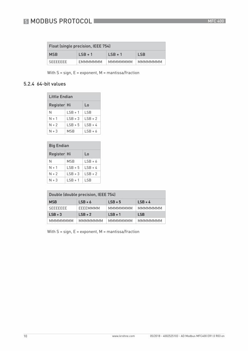
With S = sign, E = exponent, M = mantissa/fraction
5.2.4 64-bit values
With S = sign, E = exponent, M = mantissa/fraction
Float (single precision, IEEE 754)
MSB LSB + 1 LSB + 1 LSB
SEEEEEEE EMMMMMMM MMMMMMMM MMMMMMMM
Little Endian
Register Hi Lo
N LSB + 1 LSB
N + 1 LSB + 3 LSB + 2
N + 2 LSB + 5 LSB + 4
N + 3 MSB LSB + 6
Big Endian
Register Hi Lo
N MSB LSB + 6
N + 1 LSB + 5 LSB + 4
N + 2 LSB + 3 LSB + 2
N + 3 LSB + 1 LSB
Double (double precision, IEEE 754)
MSBMSBMSBMSB LSB + 6LSB + 6LSB + 6LSB + 6 LSB + 5LSB + 5LSB + 5LSB + 5 LSB + 4LSB + 4LSB + 4LSB + 4
SEEEEEEE EEEEMMMM MMMMMMMM MMMMMMMM
LSB + 3LSB + 3LSB + 3LSB + 3 LSB + 2LSB + 2LSB + 2LSB + 2 LSB + 1LSB + 1LSB + 1LSB + 1 LSBLSBLSBLSB
MMMMMMMM MMMMMMMM MMMMMMMM MMMMMMMM

MODBUS PROTOCOL 5
11
MFC 400
www.krohne.com05/2018 - 4002525103 - AD Modbus MFC400 ER1.0 R03 en
5.3 Modbus Register Addresses
The signal converter supports four types of data references, which are associated to a range of Modbus registers.
5.4 Supported Function Codes
For detailed information about the telegrams structure of all function codes refer to Supported Modbus function codes on page 33.
5.5 Error messages
When the signal converter detects an error in the requests, received in a properly formatted telegram, it will respond with an error message. The error message response telegram is formatted as follows:
The msb (most significant bit) of the requested function code is set (add 0d128 / 0x80) in the reponse telegram to indicate an error has been detected. For example, if an error were detected in a function 1 request, then the returned function code would be 0x81 (0d129).
Address range Primary tables Access rights
0...9999 Coils read + write
10000...19999 Discrete Inputs read
20000...39999 Input Registers read
40000...65535 Holding Registers read + write
INFORMATION!• Sometimes register numbers are asked for. The register numbers can be calculated by
adding a 1 to the register address.• Some systems cannot use addresses above 9999. For these systems there is the possibility to
use the listed addresses but- for Input Registers omit the leading 3 of 3xxxx;- for Holding Registers omit the leading 4 of 4xxxx.
Function code Name
dec hex
01 01 Read Single Coil
02 02 Read Descrete Inputs
03 03 Read Holding Register
04 04 Read Input Register
05 05 Write Single Coil
08 08 Diagnostics
16 10 Write Multiple Register
43 2B Encapsulated Interface Transport
Address Function Code Error Code CRC Lo CRC Hi

5 MODBUS PROTOCOL
12
MFC 400
www.krohne.com 05/2018 - 4002525103 - AD Modbus MFC400 ER1.0 R03 en
The single data character in the response telegram will indicate the type of error detected. These are as follows:
Errors due to communications faults (CRC errors, Parity errors etc.) are logged but no response is returned because the data in the received telegram is deemed unreliable. The master system can read the error logs by using the diagnostics command (for details on Function Code 0x08 refer to Diagnostics on page 13).
5.6 Device identification
Retrieve all of the identification information from the signal converter.
Modbus Function Code "Encapsulated Interface Transport" (0x2B).
Modbus Encapsulated Interface (MEI) type (0x0E).
Error Code
Name Meaning
01 ILLEGAL FUNCTION The requested function code is not supported or not valid due to the current settings of the device.
02 ILLEGAL DATA ADDRESS
The register requested is not valid or the quantity of requested registers hits invalid registers.
03 ILLEGAL DATA VALUE The requested data is invalid for the register being written.
04 SLAVE DEVICE FAILURE
An unrecoverable error occurred while the slave was attempting to perform the requested action.
06 SLAVE DEVICE BUSY The slave is unable to process the requested command because a long-duration command is in progress. The master should retransmit the message later.
Category Object Id
Object name Type Content
Basic 0x00 VendorName 16 byte ASCII String KROHNE
0x01 ProductCode 10 byte ASCII String CG number; order code for the signal converter assembly
0x02 MajorMinorRevision 7 byte ASCII String Electronic Revision number
Regular 0x03 Vendor URL 32 byte ASCII String www.krohne.com
0x04 ProductName 16 byte ASCII String MFC400
0x05 ModelName 16 byte ASCII String Modbus
0x06 UserApplicationName 16 byte ASCII String User tag, displayed on the header of the local screen

MODBUS PROTOCOL 5
13
MFC 400
www.krohne.com05/2018 - 4002525103 - AD Modbus MFC400 ER1.0 R03 en
5.7 Diagnostics
This command function permits the user to perform one of several diagnostics operations, such as retrieving the error and event logs. For further details on this command function, refer to the Modbus Application Protocol Specification V1.1b.
Modbus Function Code "Diagnostics" (0x08)
5.8 Parameters
The functions of the Modbus interface are arranged in groups of thematically coherent parameters.
Large gaps have been left between these groups of data types in order to permit expansion of the signal converter interface and compatibility with further high performance signal converters.
Some registers are protected by a custody transfer lock for use when the signal converter is used in custody transfer applications. These registers are indicated by the symbol.
The configuration of the signal converter can be changed via Modbus Holding Registers. Writing data to those registers does not take effect immediately. In order to apply the new configuration it is necessary to perform "Apply Changes". Parameters that require "Apply Changes" are indicated by the symbol. Changes that are not applied can be discarded via "Discard Changes" (details on page 14). For further information refer to Application sequences on page 28.
Sub function code Name
dec hex
00 00 Return Query Data
01 01 Restart Communication Option
04 04 Force Listen Only Mode
10 0A Clear Counters
11 0B Return Bus Message Count
12 0C Return Bus Communication Error Count
13 0D Return Bus Exception Count
14 0E Return Slave Message Count
15 0F Return Slave No Response Count
18 12 Return Bus Character Overrun Count

5 MODBUS PROTOCOL
14
MFC 400
www.krohne.com 05/2018 - 4002525103 - AD Modbus MFC400 ER1.0 R03 en
5.8.1 Device Control
The "Device Control" offers some basic functionality to operate with the signal converter. Therefore, the Modbus interface provides five coils that can be accessed via Modbus Function Code "Write Single Coil" (0x05).
Write a coil to value 1value 1value 1value 1 (ON) to initiate the action.
The flow sensor can be switched between three modes. Use the following Modbus register to request a change of the operation mode. The actual operation mode can be read via Modbus register 39000 (details on page 15).
Modbus Function Code "Write Single Coil" (0x05)
Coil Address
Name Description Display Fct. No.
1000100010001000(0x03E8)
Restart Device Restart entire signal converter D2.2.1
1001100110011001(0x03E9)
Reset Errors Clears the system error flags A3.1
1002100210021002(0x03EA)
Apply Changes Apply latest changes of configuration -
1003100310031003(0x03EB)
Discard Changes Discard all of the configuration changes made since the last "Apply Changes"
-
1004100410041004(0x03EC)
Reset to Factory Data
Resets the signal converter to factory configuration C6.6.3
Modbus Function Codes "Read Holding Registers" (0x03) and "Write Multiple Registers" (0x10)
Holding Register
Name Description Type No. of registers
Values Display Fct. No.
51000510005100051000(0XC738)
Operation Mode
Set the actual operation mode of the flow sensor
Byte 1 1 = Stop Mode3 = Measure Mode5 = Standby Mode
A.9

MODBUS PROTOCOL 5
15
MFC 400
www.krohne.com05/2018 - 4002525103 - AD Modbus MFC400 ER1.0 R03 en
5.8.2 Device Status
Modbus Function Codes "Read Discrete Inputs" (0x02)
Discrete Inputs
Name Description Type No. of registers
Values
10000100001000010000(0x2710)
Status of Custody Transfer Lock
Indicates if custody transfer lock is active or no
Bit 1 0 = unlocked1 = locked
10001100011000110001(0x2711)
Are Changes Made?
Indicates if there are unsaved changes. "Apply Changes" to save them, "Discard Changes" to work with previous settings
Bit 1 0 = no changes made1 = unsaved changes detected
Modbus Function Codes "Read Input Registers" (0x04)
Input Register
Name Type No. of registers
Values / Units Display Fct. No.
39000390003900039000(0x9858)
Actual Operation Mode Long 2 1 = Stop2 = Startup3 = Measuring5 = Standby
B2.16
39002390023900239002(0x985A)
Device Operation Time Float 2 [s] B2.1
39004390043900439004(0x985C)
NE 107 Status Groups Long 2 For further information refer to NAMUR NE 107 Event Group(s) on page 32.
-
39100391003910039100(0x98BC)
NE 107 Device Status Byte 1 Bit 7 = Failure (F)Bit 6 = reservedBit 5 = Out of Specification (S)Bit 4 = Function Check (C)Bit 3 = reservedBit 2 = Maintenance required (M)Bit 1 = reservedBit 0 = Information (I)
-
5 MODBUS PROTOCOL
16
MFC 400
www.krohne.com 05/2018 - 4002525103 - AD Modbus MFC400 ER1.0 R03 en
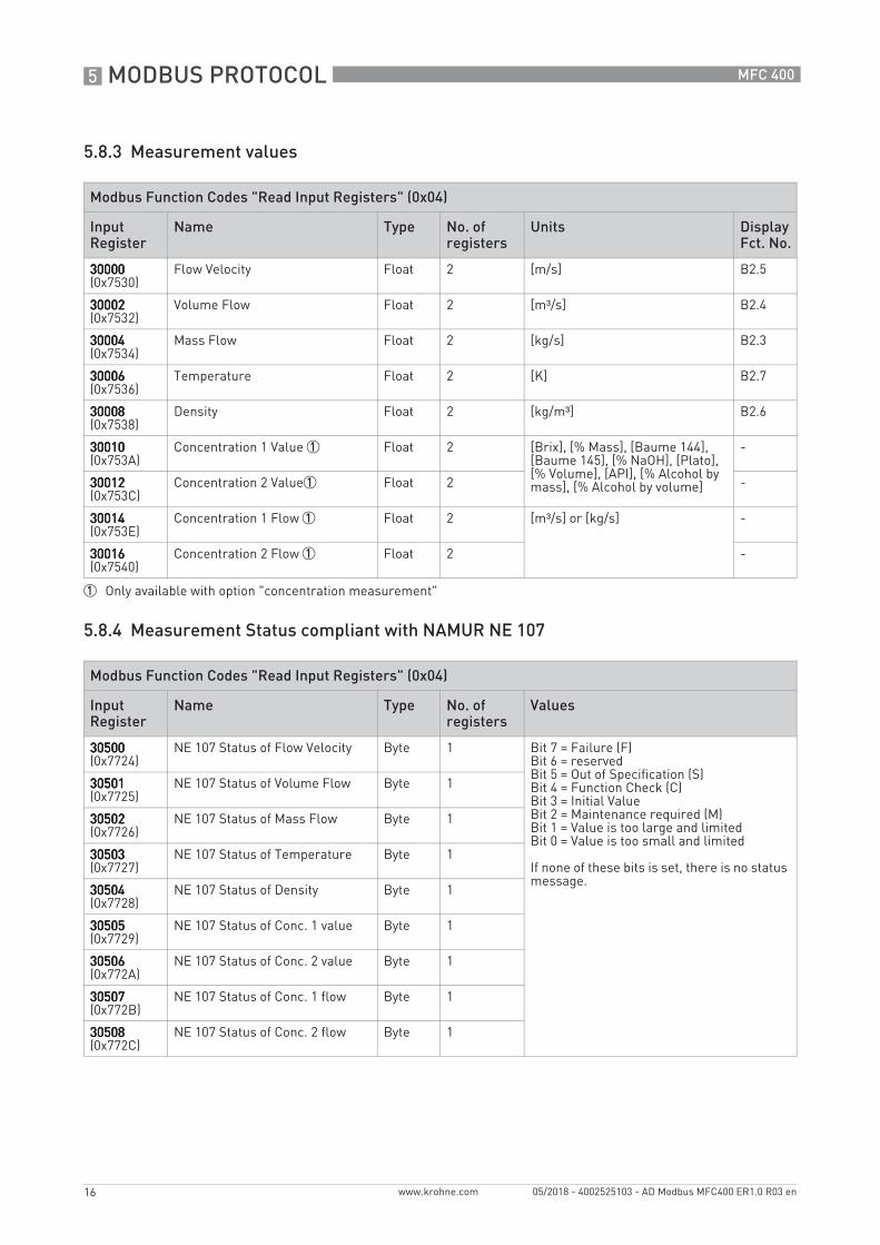
5.8.3 Measurement values
5.8.4 Measurement Status compliant with NAMUR NE 107
Modbus Function Codes "Read Input Registers" (0x04)
Input Register
Name Type No. of registers
Units Display Fct. No.
30000300003000030000(0x7530)
Flow Velocity Float 2 [m/s] B2.5
30002300023000230002(0x7532)
Volume Flow Float 2 [m³/s] B2.4
30004300043000430004(0x7534)
Mass Flow Float 2 [kg/s] B2.3
30006300063000630006(0x7536)
Temperature Float 2 [K] B2.7
30008300083000830008(0x7538)
Density Float 2 [kg/m³] B2.6
30010300103001030010(0x753A)
Concentration 1 Value 1 Float 2 [Brix], [% Mass], [Baume 144], [Baume 145], [% NaOH], [Plato], [% Volume], [API], [% Alcohol by mass], [% Alcohol by volume]
-
30012300123001230012(0x753C)
Concentration 2 Value1 Float 2 -
30014300143001430014(0x753E)
Concentration 1 Flow 1 Float 2 [m³/s] or [kg/s] -
30016300163001630016(0x7540)
Concentration 2 Flow 1 Float 2 -
1 Only available with option "concentration measurement"
Modbus Function Codes "Read Input Registers" (0x04)
Input Register
Name Type No. of registers
Values
30500305003050030500(0x7724)
NE 107 Status of Flow Velocity Byte 1 Bit 7 = Failure (F)Bit 6 = reservedBit 5 = Out of Specification (S)Bit 4 = Function Check (C)Bit 3 = Initial ValueBit 2 = Maintenance required (M)Bit 1 = Value is too large and limitedBit 0 = Value is too small and limited
If none of these bits is set, there is no status message.
30501305013050130501(0x7725)
NE 107 Status of Volume Flow Byte 1
30502305023050230502(0x7726)
NE 107 Status of Mass Flow Byte 1
30503305033050330503(0x7727)
NE 107 Status of Temperature Byte 1
30504305043050430504(0x7728)
NE 107 Status of Density Byte 1
30505305053050530505(0x7729)
NE 107 Status of Conc. 1 value Byte 1
30506305063050630506(0x772A)
NE 107 Status of Conc. 2 value Byte 1
30507305073050730507(0x772B)
NE 107 Status of Conc. 1 flow Byte 1
30508305083050830508(0x772C)
NE 107 Status of Conc. 2 flow Byte 1

MODBUS PROTOCOL 5
17
MFC 400
www.krohne.com05/2018 - 4002525103 - AD Modbus MFC400 ER1.0 R03 en
5.8.5 Auxiliary Values
5.8.6 Totaliser
Modbus Function Codes "Read Input Registers" (0x04)
Input Register
Name Type No. of registers
Units Display Fct. No.
31000310003100031000(0x7918)
Drive Level Float 2 [%] B2.11
31002310023100231002(0x791A)
Sensor A Level Float 2 [%] B2.12
31004310043100431004(0x791C)
Sensor B Level Float 2 [%] B2.13
31006310063100631006(0x791E)
Strain 1 Float 2 [Ω] B2.8
31008310083100831008(0x7920)
Strain 2 Float 2 [Ω] B2.9
31010310103101031010(0x7922)
Tube Frequency Float 2 [Hz] B2.10
31012310123101231012(0x7924)
2 Phase Signal Float 2 - B2.14
31014310143101431014(0x7926)
SE PCB Temperature Float 2 [K] B2.15
Modbus Function Codes "Read Coils" (0x01) and "Write Single Coil" (0x05)
Coil Address
Name Function Action Values Display Fct. No.
3000300030003000(0x0BB8)
Totaliser 1 Start / Stop Write 0 = stop totaliser1 = start totaliser
C4.1.8 / C4.1.9
Status Read 0 = totaliser stopped1 = totaliser running
-
3001300130013001(0x0BB9)
Totaliser 2 Start / Stop Write 0 = stop totaliser1 = start totaliser
C4.2.8 / C4.2.9
Status Read 0 = totaliser stopped1 = totaliser running
-
3002300230023002(0x0BBA)
Totaliser 3 1 Start / Stop Write 0 = stop totaliser1 = start totaliser
C4.3.8 / C4.3.9
Status Read 0 = totaliser stopped1 = totaliser running
-
3003300330033003(0x0BBB)
Totaliser 1 Reset set totaliser value to zero
Write 1 = reset totaliser C4.1.6
3004300430043004(0x0BBC)
Totaliser 2 Reset set totaliser value to zero
Write 1 = reset totaliser C4.2.6
3005300530053005(0x0BBD)
Totaliser 3 Reset 1
set totaliser value to zero
Write 1 = reset totaliser C4.3.6
1 Only available in signal converters with "modular carrier"
5 MODBUS PROTOCOL
18
MFC 400
www.krohne.com 05/2018 - 4002525103 - AD Modbus MFC400 ER1.0 R03 en
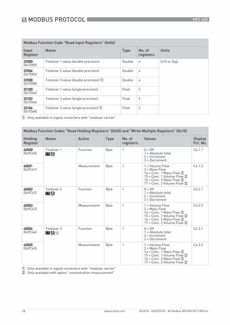
Modbus Function Code "Read Input Registers" (0x04)
Input Register
Name Type No. of registers
Units
32000320003200032000(0x7D00)
Totaliser 1 value (double precision) Double 4 [m³] or [kg]
32004320043200432004(0x7D04)
Totaliser 2 value (double precision) Double 4
32008320083200832008(0x7D08)
Totaliser 3 value (double precision) 1 Double 4
32100321003210032100(0x7D64)
Totaliser 1 value (single precision) Float 2
32102321023210232102(0x7D66)
Totaliser 2 value (single precision) Float 2
32104321043210432104(0x7D68)
Totaliser 3 value (single precision) 1 Float 2
1 Only available in signal converters with "modular carrier"
Modbus Function Codes "Read Holding Registers" (0x03) and "Write Multiple Registers" (0x10)
Holding Register
Name Action Type No. of registers
Values Display Fct. No.
40000400004000040000(0x9C40)
Totaliser 1 Function Byte 1 0 = Off1 = Absolute total2 = Increment3 = Decrement
C4.1.1
40001400014000140001(0x9C41)
Measurement Byte 1 1 = Volume Flow2 = Mass Flow14 = Conc. 1 Mass Flow 215 = Conc. 1 Volume Flow 216 = Conc. 2 Mass Flow 217 = Conc. 2 Volume Flow 2
C4.1.2
40002400024000240002(0x9C42)
Totaliser 2 Function Byte 1 0 = Off1 = Absolute total2 = Increment3 = Decrement
C4.2.1
40003400034000340003(0x9C43)
Measurement Byte 1 1 = Volume Flow2 = Mass Flow14 = Conc. 1 Mass Flow 215 = Conc. 1 Volume Flow 216 = Conc. 2 Mass Flow 217 = Conc. 2 Volume Flow 2
C4.2.2
40004400044000440004(0x9C44)
Totaliser 3 1
Function Byte 1 0 = Off1 = Absolute total2 = Increment3 = Decrement
C4.3.1
40005400054000540005(0x9C45)
Measurement Byte 1 1 = Volume Flow2 = Mass Flow14 = Conc. 1 Mass Flow 215 = Conc. 1 Volume Flow 216 = Conc. 2 Mass Flow 217 = Conc. 2 Volume Flow 2
C4.3.2
1 Only available in signal converters with "modular carrier"2 Only available with option "concentration measurement"

MODBUS PROTOCOL 5
19
MFC 400
www.krohne.com05/2018 - 4002525103 - AD Modbus MFC400 ER1.0 R03 en
Modbus Function Codes "Read Holding Registers" (0x03) and "Write Multiple Registers" (0x10)
Holding Register
Name Action Type No. of registers
Units Display Fct. No.
40500405004050040500(0x9E34)
Totaliser 1 Low Flow Cut-Off Value
Float 2 [m³/s] or [kg/s] C4.1.3
40502405024050240502(0x9E36)
Time Constant 0...100 [s] C4.1.4
40504405044050440504(0x9E38)
Set or Read Value [m³] or [kg] C4.1.7
40506405064050640506(0x9E3A)
Preset [m³] or [kg] C4.1.5
40508405084050840508(0x9E3C)
Totaliser 2 Low Flow Cut-Off Value
Float 2 [m³/s] or [kg/s] C4.2.3
40510405104051040510(0x9E3E)
Time Constant 0...100 [s] C4.2.4
40512405124051240512(0x9E40)
Set or Read Value [m³] or [kg] C4.2.7
40514405144051440514(0x9E42)
Preset [m³] or [kg] C4.2.5
40516405164051640516(0x9E44)
Totaliser 3 1
Low Flow Cut-Off Value
Float 2 [m³/s] or [kg/s] C4.3.3
40518405184051840518(0x9E46)
Time Constant 0...100 [s] C4.3.4
40520405204052040520(0x9E48)
Set or Read Value [m³] or [kg] C4.3.7
40522405224052240522(0x9E4A)
Preset [m³] or [kg] C4.3.5
1 Only available in signal converters with "modular carrier"
5 MODBUS PROTOCOL
20
MFC 400
www.krohne.com 05/2018 - 4002525103 - AD Modbus MFC400 ER1.0 R03 en
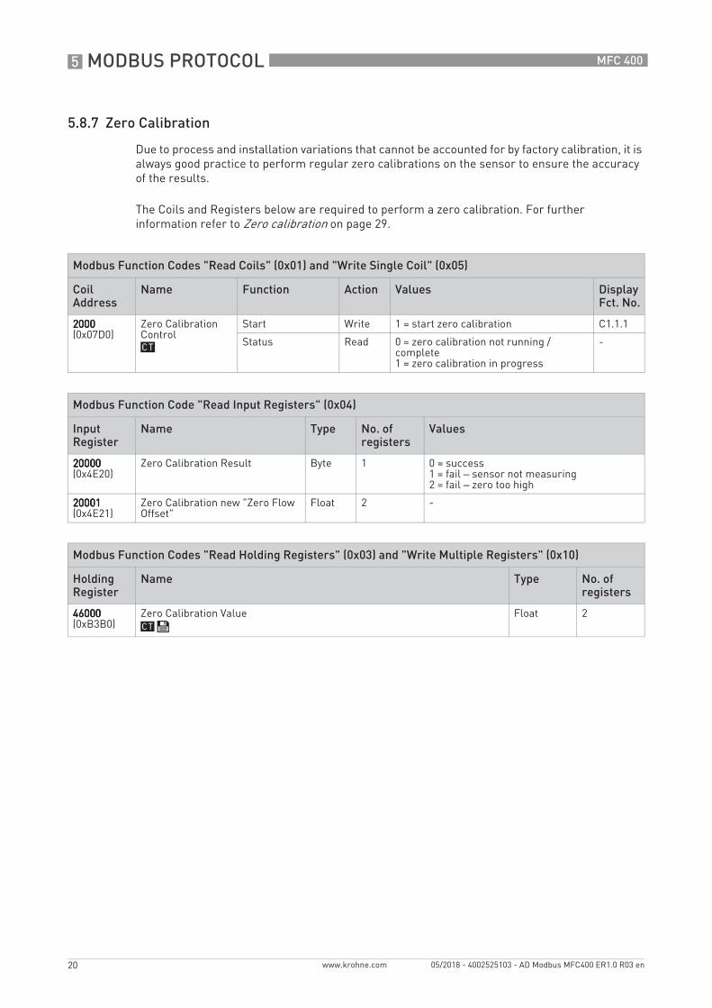
5.8.7 Zero Calibration
Due to process and installation variations that cannot be accounted for by factory calibration, it is always good practice to perform regular zero calibrations on the sensor to ensure the accuracy of the results.
The Coils and Registers below are required to perform a zero calibration. For further information refer to Zero calibration on page 29.
Modbus Function Codes "Read Coils" (0x01) and "Write Single Coil" (0x05)
Coil Address
Name Function Action Values Display Fct. No.
2000200020002000(0x07D0)
Zero Calibration Control
Start Write 1 = start zero calibration C1.1.1
Status Read 0 = zero calibration not running / complete1 = zero calibration in progress
-
Modbus Function Code "Read Input Registers" (0x04)
Input Register
Name Type No. of registers
Values
20000200002000020000(0x4E20)
Zero Calibration Result Byte 1 0 = success1 = fail – sensor not measuring2 = fail – zero too high
20001200012000120001(0x4E21)
Zero Calibration new "Zero Flow Offset"
Float 2 -
Modbus Function Codes "Read Holding Registers" (0x03) and "Write Multiple Registers" (0x10)
Holding Register
Name Type No. of registers
46000460004600046000(0xB3B0)
Zero Calibration Value Float 2
MODBUS PROTOCOL 5
21
MFC 400
www.krohne.com05/2018 - 4002525103 - AD Modbus MFC400 ER1.0 R03 en
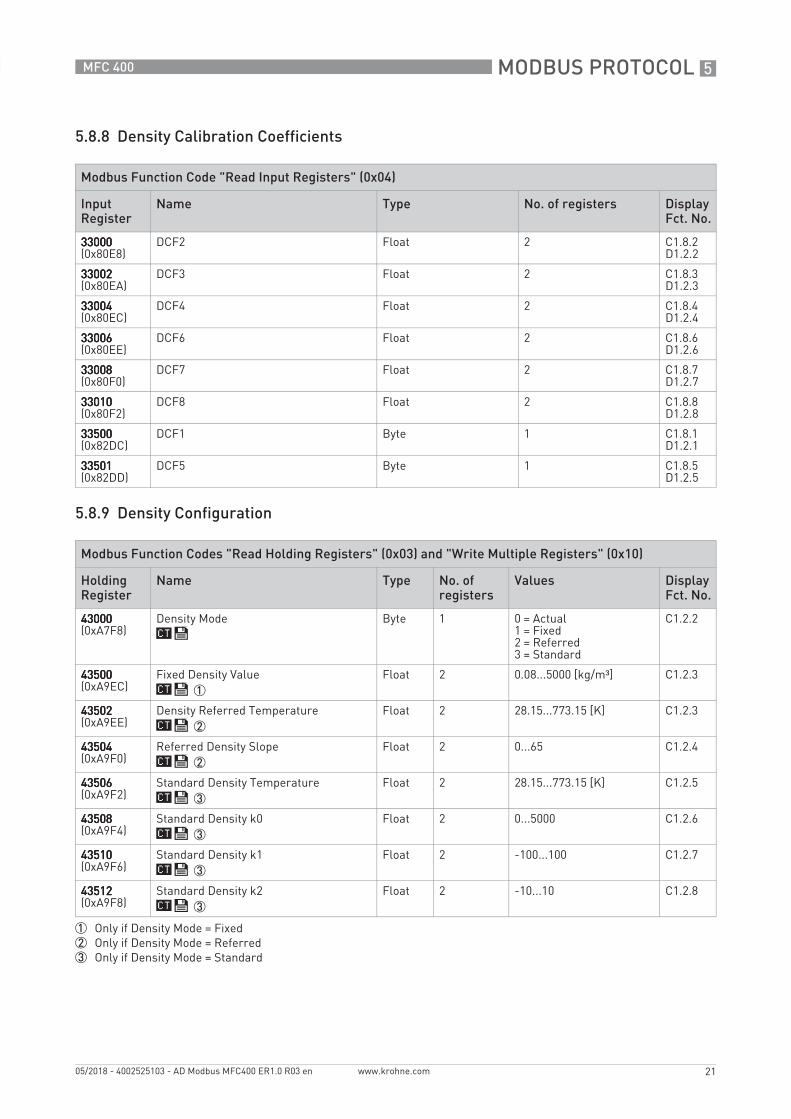
5.8.8 Density Calibration Coefficients
5.8.9 Density Configuration
Modbus Function Code "Read Input Registers" (0x04)
Input Register
Name Type No. of registers Display Fct. No.
33000330003300033000(0x80E8)
DCF2 Float 2 C1.8.2D1.2.2
33002330023300233002(0x80EA)
DCF3 Float 2 C1.8.3D1.2.3
33004330043300433004(0x80EC)
DCF4 Float 2 C1.8.4D1.2.4
33006330063300633006(0x80EE)
DCF6 Float 2 C1.8.6D1.2.6
33008330083300833008(0x80F0)
DCF7 Float 2 C1.8.7D1.2.7
33010330103301033010(0x80F2)
DCF8 Float 2 C1.8.8D1.2.8
33500335003350033500(0x82DC)
DCF1 Byte 1 C1.8.1D1.2.1
33501335013350133501(0x82DD)
DCF5 Byte 1 C1.8.5D1.2.5
Modbus Function Codes "Read Holding Registers" (0x03) and "Write Multiple Registers" (0x10)
Holding Register
Name Type No. of registers
Values Display Fct. No.
43000430004300043000(0xA7F8)
Density Mode Byte 1 0 = Actual1 = Fixed2 = Referred3 = Standard
C1.2.2
43500435004350043500(0xA9EC)
Fixed Density Value 1
Float 2 0.08...5000 [kg/m³] C1.2.3
43502435024350243502(0xA9EE)
Density Referred Temperature 2
Float 2 28.15...773.15 [K] C1.2.3
43504435044350443504(0xA9F0)
Referred Density Slope 2
Float 2 0...65 C1.2.4
43506435064350643506(0xA9F2)
Standard Density Temperature 3
Float 2 28.15...773.15 [K] C1.2.5
43508435084350843508(0xA9F4)
Standard Density k0 3
Float 2 0...5000 C1.2.6
43510435104351043510(0xA9F6)
Standard Density k1 3
Float 2 -100...100 C1.2.7
43512435124351243512(0xA9F8)
Standard Density k2 3
Float 2 -10...10 C1.2.8
1 Only if Density Mode = Fixed2 Only if Density Mode = Referred3 Only if Density Mode = Standard

5 MODBUS PROTOCOL
22
MFC 400
www.krohne.com 05/2018 - 4002525103 - AD Modbus MFC400 ER1.0 R03 en
5.8.10 Filters
5.8.11 System Control
Modbus Function Codes "Read Holding Registers" (0x03) and "Write Multiple Registers" (0x10)
Holding Register
Name Type No. of registers
Values Display Fct. No.
45000450004500045000(0xAFC8)
Flow Direction Byte 1 1 = Forwards2 = Backwards
C1.3.1
45500455004550045500(0xB1BC)
2 Phase Threshold Float 2 0...1000 C1.5.3
45502455024550245502(0xB1BE)
Pipe Diameter Float 2 0.001...0.5 [m] C1.3.1
45504455044550445504(0xB1C0)
User Flow Offset Float 2 -32...32 C1.1.2
45506455064550645506(0xB1C2)
Low Flow Cut-Off Float 2 0...10 [%] C1.3.4
45508455084550845508(0xB1C4)
Pressure Suppression Time Float 2 0...20 [s] C1.3.2
45510455104551045510(0xB1C6)
Pressure Suppression Cut-Off Float 2 0...10 [%] C1.3.3
45512455124551245512(0xB1C8)
Flow Correction Float 2 -10...10 [%] C1.1.4
Modbus Function Codes "Read Holding Registers" (0x03) and "Write Multiple Registers" (0x10)
Holding Register
Name Type No. of registers
Values Display Fct. No.
44000440004400044000(0xABE0)
Function Byte 1 1 = Off / No Action2 = Flow=0
C1.4.1
44001440014400144001(0xABE1)
Condition Byte 1 0 = Density1 = Temperature
C1.4.2
44500445004450044500(0xADD4)
Density Min. Limit Float 2 0.08...5000 [kg/m³] C1.4.3
44502445024450244502(0xADD6)
Density Max. Limit Float 2 0.08...5000 [kg/m³] C1.4.4
44504445044450444504(0xADD8)
Temperature Min. Limit Float 2 73...773 [K] C1.4.3
44506445064450644506(0xADDA)
Temperature Max. Limit Float 2 73...773 [K] C1.4.4

MODBUS PROTOCOL 5
23
MFC 400
www.krohne.com05/2018 - 4002525103 - AD Modbus MFC400 ER1.0 R03 en
5.8.12 Calibration Coefficients
Modbus Function Code "Read Input Registers" (0x04)
Input Register
Name Type No. of registers Display Fct. No.
34000340003400034000(0x84D0)
CF1 Float 2 D1.1.1
34002340023400234002(0x84D2)
CF2 Float 2 D1.1.2
34004340043400434004(0x84D4)
CF3 Float 2 D1.1.3
34006340063400634006(0x84D6)
CF4 Float 2 D1.1.4
34008340083400834008(0x84D8)
CF5 Float 2 D1.1.5
34010340103401034010(0x84DA)
CF6 Float 2 D1.1.6
34012340123401234012(0x84DC)
CF7 Float 2 D1.1.7
34014340143401434014(0x84DE)
CF8 Float 2 D1.1.8
34016340163401634016(0x84E0)
CF11 Float 2 D1.1.9
34018340183401834018(0x84E2)
CF12 Float 2 D1.1.10
34020340203402034020(0x84E4)
CF13 Float 2 D1.1.11
34022340223402234022(0x84E6)
CF14 Float 2 D1.1.12
34024340243402434024(0x84E8)
CF15 Float 2 D1.1.13
34026340263402634026(0x84EA)
CF16 Float 2 D1.1.14
34028340283402834028(0x84EC)
CF17 Float 2 D1.1.15
34030340303403034030(0x84EE)
CF18 Float 2 D1.1.16
34032340323403234032(0x84F0)
CF19 Float 2 D1.1.17
34034340343403434034(0x84F2)
CF20 Float 2 D1.1.18
34036340363403634036(0x84F4)
CF21 Float 2 D1.1.19
34038340383403834038(0x84F6)
CF22 Float 2 D1.1.20
34040340403404034040(0x84F8)
CF23 Float 2 D1.1.21
34042340423404234042(0x84FA)
CF24 Float 2 D1.1.22
34044340443404434044(0x84FC)
CF26 Float 2 D1.1.24
5 MODBUS PROTOCOL
24
MFC 400
www.krohne.com 05/2018 - 4002525103 - AD Modbus MFC400 ER1.0 R03 en
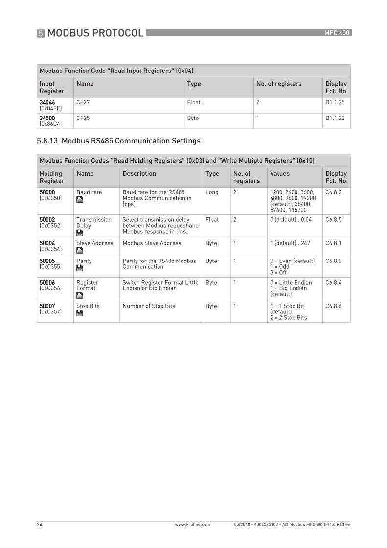
5.8.13 Modbus RS485 Communication Settings
34046340463404634046(0x84FE)
CF27 Float 2 D1.1.25
34500345003450034500(0x86C4)
CF25 Byte 1 D1.1.23
Modbus Function Codes "Read Holding Registers" (0x03) and "Write Multiple Registers" (0x10)
Holding Register
Name Description Type No. of registers
Values Display Fct. No.
50000500005000050000(0xC350)
Baud rate Baud rate for the RS485 Modbus Communication in [bps]
Long 2 1200, 2400, 3600, 4800, 9600, 19200 (default), 38400, 57600, 115200
C6.8.2
50002500025000250002(0xC352)
Transmission Delay
Select transmission delay between Modbus request and Modbus response in [ms]
Float 2 0 (default)...0.04 C6.8.5
50004500045000450004(0xC354)
Slave Address Modbus Slave Address Byte 1 1 (default)...247 C6.8.1
50005500055000550005(0xC355)
Parity Parity for the RS485 Modbus Communication
Byte 1 0 = Even (default)1 = Odd3 = Off
C6.8.3
50006500065000650006(0xC356)
Register Format
Switch Register Format Little Endian or Big Endian
Byte 1 0 = Little Endian1 = Big Endian (default)
C6.8.4
50007500075000750007(0xC357)
Stop Bits Number of Stop Bits Byte 1 1 = 1 Stop Bit (default)2 = 2 Stop Bits
C6.8.6
Modbus Function Code "Read Input Registers" (0x04)
Input Register
Name Type No. of registers Display Fct. No.

MODBUS PROTOCOL 5
25
MFC 400
www.krohne.com05/2018 - 4002525103 - AD Modbus MFC400 ER1.0 R03 en
5.8.14 NAMUR NE 107 Variable Event Group(s)
The following eight event groups can be mapped to any status signal.
For further information refer to section "Status messages and diagnostic information" in the signal converter standard manual.
Legal values for those registers:
• 128: Failure (F)• 32: Out Of Specification (S)• 16: Function Check (C)• 4: Maintenance Request (M)• 1: Information (I)
Modbus Function Codes "Read Holding Registers" (0x03) and "Write Multiple Registers" (0x10)
Holding Register
Description Status Group Type No. of registers
Default Value Display Fct. No.
52016520165201652016(0xCB30)
Status Signal of Event Group 15
Proc: Current Input Byte 1 128Failure (F)
C1.5.9
52017520175201752017(0xCB31)
Status Signal of Event Group 14
Electr: IO Connection Byte 1 32Out Of Specification (S)
C1.5.14
52018520185201852018(0xCB32)
Status Signal of Event Group 13
Proc: Signal Search Byte 1 128Failure (F)
C1.5.8
52019520195201952019(0xCB33)
Status Signal of Event Group 12
Proc: 2 Phase Flow Byte 1 32Out Of Specification (S)
C1.5.10
52020520205202052020(0xCB34)
Status Signal of Event Group 11
Proc: Signal Low Byte 1 32Out Of Specification (S)
C1.5.7
52021520215202152021(0xCB35)
Status Signal of Event Group 10
Config: Totaliser Byte 1 32Out Of Specification (S)
C1.5.12
52022520225202252022(0xCB36)
Status Signal of Event Group 9
Proc: System Control Byte 1 1Information (I)
C1.5.11
52023520235202352023(0xCB37)
Status Signal of Event Group 8
Electr: Power Failure Byte 1 32Out Of Specification (S)
C1.5.13

5 MODBUS PROTOCOL
26
MFC 400
www.krohne.com 05/2018 - 4002525103 - AD Modbus MFC400 ER1.0 R03 en
5.8.15 Concentration 1
INFORMATION!Only available with option "concentration measurement".
Modbus Function Codes "Read Holding Registers" (0x03) and "Write Multiple Registers" (0x10)
Holding Register
Name Type No. of registers
Values Display Fct. No.
42000420004200042000(0xA410)
Function Byte 1 0 = Off2 = Brix3 = % Mass4 = Baume 1445 = Baume 1456 = % NaOH7 = Plate8 = % Volume9 = API10 = % Alcohol by mass11 = % Alcohol by volume
C2.2.1
42001420014200142001(0xA411)
Product Byte 1 0 = % of Product A1 = % of Product B
C2.2.3
42002420024200242002(0xA412)
CCF01 Byte 1 0 = linear1 = non linear
C2.4.1
42003420034200342003(0xA413)
CCF05 Byte 1 0 = pure water1 = town water2 = other
C2.4.5
42050420504205042050(0xA442)
Offset Float 2 -100...100 [%] C2.2.2
42052420524205242052(0xA444)
CCF02 Float 2 - C2.4.2
42054420544205442054(0xA446)
CCF03 Float 2 - C2.4.3
42056420564205642056(0xA448)
CCF04 Float 2 - C2.4.4
42058420584205842058(0xA44A)
CCF06 Float 2 - C2.4.6
42060420604206042060(0xA44C)
CCF07 Float 2 - C2.4.7
42062420624206242062(0xA44E)
CCF08 Float 2 - C2.4.8
42064420644206442064(0xA450)
CCF09 Float 2 - C2.4.9
42066420664206642066(0xA452)
CCF10 Float 2 - C2.4.10
42068420684206842068(0xA454)
CCF11 Float 2 - C2.4.11
42070420704207042070(0xA456)
CCF12 Float 2 - C2.4.12

MODBUS PROTOCOL 5
27
MFC 400
www.krohne.com05/2018 - 4002525103 - AD Modbus MFC400 ER1.0 R03 en
5.8.16 Concentration 2
INFORMATION!Only available with option "concentration measurement".
Modbus Function Codes "Read Holding Registers" (0x03) and "Write Multiple Registers" (0x10)
Holding Register
Name Type No. of registers
Values Display Fct. No.
42100421004210042100(0xA474)
Function Byte 1 0 = Off2 = Brix3 = % Mass4 = Baume 1445 = Baume 1456 = % NaOH7 = Plate8 = % Volume9 = API10 = % Alcohol by mass11 = % Alcohol by volume
C2.3.1
42101421014210142101(0xA475)
Product Byte 1 0 = % of Product A1 = % of Product B
C2.3.3
42102421024210242102(0xA476)
CCF01 Byte 1 0 = linear1 = non linear
C2.5.1
42103421034210342103(0xA477)
CCF05 Byte 1 0 = pure water1 = town water2 = other
C2.5.5
42150421504215042150(0xA4A6)
Offset Float 2 -100...100 [%] C2.3.2
42152421524215242152(0xA4A8)
CCF02 Float 2 - C2.5.2
42154421544215442154(0xA4AA)
CCF03 Float 2 - C2.5.3
42156421564215642156(0xA4AC)
CCF04 Float 2 - C2.5.4
42158421584215842158(0xA4AE)
CCF06 Float 2 - C2.5.6
42160421604216042160(0xA4B0)
CCF07 Float 2 - C2.5.7
42162421624216242162(0xA4B2)
CCF08 Float 2 - C2.5.8
42164421644216442164(0xA4B4)
CCF09 Float 2 - C2.5.9
42166421664216642166(0xA4B6)
CCF10 Float 2 - C2.5.10
42168421684216842168(0xA4B8)
CCF11 Float 2 - C2.5.11
42170421704217042170(0xA4BA)
CCF12 Float 2 - C2.5.12

6 APPLICATION SEQUENCES
28
MFC 400
www.krohne.com 05/2018 - 4002525103 - AD Modbus MFC400 ER1.0 R03 en
6.1 Saving and restoring the configuration setting
The example assumes slave address 1 for Modbus telegram.
1 Start
2 Change Configuration
2a Write Holding Register(s)
2b [changes done]
3a [discard]
3b [apply]
4 Discard Changes
4a Set Coil 1003 (0x03EB)MB-Telegram: 01 05 03 EB FF 00 + CRC
5 Previous configuration retained
6 Apply Changes
6a Set Coil 1002 (0x03EA)MB-Telegram: 01 05 03 EA FF 00 + CRC
7 New configuration applied
APPLICATION SEQUENCES 6
29
MFC 400
www.krohne.com05/2018 - 4002525103 - AD Modbus MFC400 ER1.0 R03 en
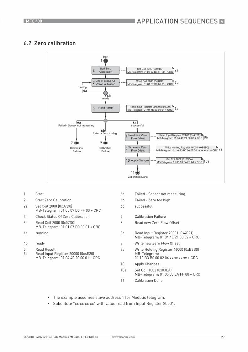
6.2 Zero calibration
• The example assumes slave address 1 for Modbus telegram.• Substitute "xx xx xx xx" with value read from Input Register 20001.
1 Start 6a Failed - Sensor not measuring
2 Start Zero Calibration 6b Failed - Zero too high
2a Set Coil 2000 (0x07D0)MB-Telegram: 01 05 07 D0 FF 00 + CRC
6c successful
3 Check Status Of Zero Calibration 7 Calibration Failure
3a Read Coil 2000 (0x07D0)MB-Telegram: 01 01 07 D0 00 01 + CRC
8 Read new Zero Flow Offset
4a running 8a Read Input Register 20001 (0x4E21)MB-Telegram: 01 04 4E 21 00 02 + CRC
4b ready 9 Write new Zero Flow Offset
55a
Read ResultRead Input Register 20000 (0x4E20)MB-Telegram: 01 04 4E 20 00 01 + CRC
9a Write Holding Register 46000 (0xB3B0)MB-Telegram:01 10 B3 B0 00 02 04 xx xx xx xx + CRC
10 Apply Changes
10a Set Coil 1002 (0x03EA)MB-Telegram: 01 05 03 EA FF 00 + CRC
11 Calibration Done

7 TROUBLESHOOTING
30
MFC 400
www.krohne.com 05/2018 - 4002525103 - AD Modbus MFC400 ER1.0 R03 en
7.1 No response to Modbus requests
There are a number of possibilities why no response would be received from the signal converter. Here is a list of some of the more obvious things to check:
• Check that there is an appropriate voltage input on the V+ and V- terminals of the signal converter.
• Ensure that there is continuity between the A and B input terminals and their associated terminals at the master device. Check that A and B are connected correctly (details on page 6). Ensure that there is a proper "Common" connection between the master device and the signal converter.
• The signal converter will ignore messages that are not addressed to it, or any message that contains fundamental formatting errors. So, check that the Address ID that is being requested is correct, the default value is 1. Check that the transmission rate (default = 19200 Baud) and format (default = 8 data bits, even parity and 1 stop bit) are correct.
7.2 Communication errors
Intermittent communication errors can have a number of causes, almost all of which can be attributed to the quality of the connection between the master device and the signal converter, such as:
• Low quality connections at the terminals of the signal converter or master device. Ensure that good contact is being made and that the connections are not frayed or corroded.
• Cable lengths and/or cable capacitance are too great for the data rates being used.• Powerful sources of electromagnetic interference in close proximity to the path of the cable
route.• It is common to use converter devices to connect the Modbus RS485 output of the signal
converter to the serial RS232 port or USB port of a host PC using off-the-shelf protocol converters. Many of these, especially USB based converters will have problems operating the Modbus interface as it is a timing critical protocol. Where possible, a dedicated RS485 interface PC card should be used.
7.3 Responding with exception "Illegal Function"
There can be two reasons why this error response will be returned by the signal converter in answer to a request:
• The function being requested is not valid for the signal converter; check the list of valid Modbus functions. For further information refer to Supported Function Codes on page 11.
• An attempt is being made to write to a register that is protected by the Custody Transfer Lock.

TROUBLESHOOTING 7
31
MFC 400
www.krohne.com05/2018 - 4002525103 - AD Modbus MFC400 ER1.0 R03 en
7.4 Responding with exception "Illegal Data Address"
There are four reasons why the signal converter will return an "Illegal Data Address" error message when the master device makes a request.
a) The register address being requested is not supported by the signal conveter, check the requested register against the registers specified in the section "Parameters".
b) Although the start address is valid, when accessing multiple registers the number of registers requested may extend beyond the end of the valid address range for that group of variables. Check the number of variables requested and ensure that the last register address is valid.
c) The number of registers requested is not correct for the data type being requested. For example, if registers containing floating point variables are requested then the number of requested registers must be a multiple of 2 as the floating point variables are held in two consecutive registers. For double precision floating point variables the number of registers requested must be a multiple of 4.
d) From c) above, the system will respond with an "Invalid Address" error when an attempt is made to access the associated registers of a multi-register variable, for example when access to the second register of a floating point variable is attempted. i.e. if an attempt is made to access Input register 30001, which contains the second half of the variable accessed by Input register 30000.
7.5 Responding with exception "Illegal Data Value"
When the signal converter responds with an "Illegal Data Value", it is because the value being written to a holding register in the signal converter is beyond the permitted limits for that register. The limits for each holding register are indicated in the section "Parameters".

8 APPENDIX
32
MFC 400
www.krohne.com 05/2018 - 4002525103 - AD Modbus MFC400 ER1.0 R03 en
8.1 NAMUR NE 107 Event Group(s)
Modbus Input Register
39004 39005
Byte 0 Byte 1 Byte 2 Byte 3
Byte Bit Status signal
Event group
3 7 - reserved
6 - reserved
5 - reserved
4 - reserved
3 - reserved
2 I Config: No Meas. Value
1 I Electr: Operation Info
0 - -
2 7 F Proc: Current Input 1
6 S Electr: IO Connection 1
5 F Proc: Signal Search 1
4 S Proc: 2 Phase Flow 1
3 S Proc: Signal Low 1
2 S Config: Totaliser 1
1 I Proc: System Control 1
0 I Electr: Power Failure 1
1 7 S Sensor
6 S Electronics
5 S Configuration
4 S Process
3 M Sensor
2 M Electronics
1 M Configuration
0 M Process
0 7 F Sensor
6 F Electronics
5 F Configuration
4 F Process
3 C Sensor
2 C Electronics
1 C Configuration
0 C Process
1 Those event groups can be mapped to any status signals.

APPENDIX 8
33
MFC 400
www.krohne.com05/2018 - 4002525103 - AD Modbus MFC400 ER1.0 R03 en
8.2 NAMUR NE 107 status signals
8.3 Supported Modbus function codes
Function Code 0x01: Read Coils
Function Code 0x02: Read Discrete Inputs
F FailureFailureFailureFailureOutput signal invalid due to malfunction in the signal converter.
C Function CheckFunction CheckFunction CheckFunction CheckOutput signal temporarily invalid due to ongoing work on the signal converter.
S Out of specificationOut of specificationOut of specificationOut of specification• Deviations from the permissible ambient or process conditions determined by
the signal converter itself through self-monitoring.• Faults in the signal converter itself indicate that the measuring uncertainty of
flow sensors or deviations from the set value in actuators is probably greater than expected under operating conditions.
M Maintenance requiredMaintenance requiredMaintenance requiredMaintenance requiredAlthough the output signal is valid, the wear reserve is nearly exhausted or a function will soon be restricted due to operational conditions.
Request Response Error
Function 0x01 Function 0x01 Function 0x81
Starting Address Hi
0x00 to 0xFF Byte Count n Exception Code 0x01 / 0x02 / 0x03 / 0x04
Starting Address Lo
0x00 to 0xFF Coil n Status
Quantity of Coils Hi
n (0x00 to 0x07) ... ...
Quantity of Coils Lo
n (0x01 to 0xFF)
max Quantity: 0x07D0
Request Response Error
Function 0x02 Function 0x02 Function 0x82
Starting Address Hi
0x00 to 0xFF Byte Count n Exception Code 0x01 / 0x02 / 0x03 / 0x04
Starting Address Lo
0x00 to 0xFF Input n Status
Quantity of Registers Hi
n (0x00 to 0x07) ... ...
Quantity of Registers Lo
n (0x01 to 0xFF)
max Quantity: 0x07D0

8 APPENDIX
34
MFC 400
www.krohne.com 05/2018 - 4002525103 - AD Modbus MFC400 ER1.0 R03 en
Function Code 0x03: Read Holding Registers
Function Code 0x04: Read Input Register
Function Code 0x05: Write Single Coil
Function Code 0x08: Diagnostics
Request Response Error
Function 0x03 Function 0x03 Function 0x83
Starting Address Hi
0x00 to 0xFF Byte Count 2 * n Exception Code 0x01 / 0x02 / 0x03 / 0x04
Starting Address Lo
0x00 to 0xFF Register n Value Hi
Quantity of Registers Hi
0x00 Register n Value Lo
Quantity of Registers Lo
n (0x01 to 0x7D) ... ...
Request Response Error
Function 0x04 Function 0x04 Function 0x84
Starting Address Hi
0x00 to 0xFF Byte Count 2 * n Exception Code 0x01 / 0x02 / 0x03 / 0x04
Starting Address Lo
0x00 to 0xFF Input Register n Hi
Quantity of Input Registers Hi
0x00 Input Register n Lo
Quantity of Input Registers Lo
n (0x01 to 0x7D) ... ...
Request Response Error
Function 0x05 Function 0x05 Function 0x85
Output Address Hi 0x00 to 0xFF Output Address Hi 0x00 to 0xFF Exception Code 0x01 / 0x02 / 0x03 / 0x04
Output Address Lo 0x00 to 0xFF Output Address Lo 0x00 to 0xFF
Output Value Hi 0x00 or 0xFF Output Value Hi 0x00 or 0xFF
Output Value Lo 0x00 Output Value Lo 0x00
Request Response Error
Function 0x08 Function 0x08 Function 0x88
Sub-function Hi 0x00 to 0xFF Sub-function Hi 0x00 to 0xFF Exception Code 0x01 / 0x03 / 0x04
Sub-function Lo 0x00 to 0xFF Sub-function Lo 0x00 to 0xFF
Data n Hi 0x00 to 0xFF Data n Hi 0x00 to 0xFF
Data n Lo 0x00 to 0xFF Data n Lo 0x00 to 0xFF
... ... ... ...

APPENDIX 8
35
MFC 400
www.krohne.com05/2018 - 4002525103 - AD Modbus MFC400 ER1.0 R03 en
Function Code 0x10: Write Multiple Registers
Function Code 0x2B: Encapsulated Interface Transport 0x0E Read Device Identification
Request Response Error
Function 0x10 Function 0x10 Function 0x90
Starting Address Hi
0x00 to 0xFF Starting Address Hi
0x00 to 0xFF Exception Code 0x01 / 0x02 / 0x03 / 0x04
Starting Address Lo
0x00 to 0xFF Starting Address Lo
0x00 to 0xFF
Quantity of Registers Hi
0x00 Quantity of Registers Hi
0x00
Quantity of Registers Lo
0x01 to 0x7B Quantity of Registers Lo
0x01 to 0x7B
Byte Count 2 * n (0x02 to 0xFF)
Register n Value Hi
0x00 to 0xFF
Register n Value Lo
0x00 to 0xFF
... ...
Request Response Error
Function 0x2B Function 0x2B Function 0xAB
MEI Type 0x0E MEI Type 0x0E Exception Code 0x01 / 0x02 / 0x03 / 0x04
Read Device ID Code
0x01 / 0x02(0x03 / 0x04)
Read Device ID Code
0x01 / 0x02(0x03 / 0x04)
Object ID 0x00 to 0xFF Conformity Level 0x02 (0x01 / 0x03 / 0x04)
More Follows 0x00 (or 0xFF)
Next Object ID 0x00 to 0xFF
Number of Objects
0x01 to 0x07 (0xFF)
Object n ID 0x00 to 0xFF
Object n length 0x00 to 0xFF
Object n value n (1...254 bytes)
... ...
8 APPENDIX
36
MFC 400
www.krohne.com 05/2018 - 4002525103 - AD Modbus MFC400 ER1.0 R03 en
8.4 Number format
• Hexadecimal values are written in the format 0xNNNN, where NNNN is the hexadecimal value.
• Decimal values are written in the format 0dNNNN or NNNN, where NNNN is the decimal value.
8.5 Glossary
RTU Remote Terminal Unit mode is a Modbus serial transmission mode
RS232 TIA/EIA-232 Standard
RS485 TIA/EIA-485 Standard
Master/Client A device that polls one or more slave devices and always initiates communication
Slave/Server A device that responds to requests from a master and never initiates communication
CRC Cyclic Redundancy Checksum
Register A Modbus data object corresponding to a word (16 bits)
Coil A Modbus data object corresponding to a single bit
LSB Least Significant Byte
MSB Most Significant Byte
lsb least significant bit
msb most significant bit

NOTES 9
37
MFC 400
www.krohne.com05/2018 - 4002525103 - AD Modbus MFC400 ER1.0 R03 en

9 NOTES
38
MFC 400
www.krohne.com 05/2018 - 4002525103 - AD Modbus MFC400 ER1.0 R03 en

NOTES 9
39
MFC 400
www.krohne.com05/2018 - 4002525103 - AD Modbus MFC400 ER1.0 R03 en

KROHNE – Process instrumentation and measurement solutions
• Flow
• Level
• Temperature
• Pressure
• Process Analysis
• Services
Head Office KROHNE Messtechnik GmbHLudwig-Krohne-Str. 547058 Duisburg (Germany)Tel.: +49 203 301 0Fax: +49 203 301 [email protected]
© K
RO
HN
E 05
/201
8 -
4002
5251
03 -
AD
Mod
bus
MFC
400
ER1.
0 R
03 e
n -
Subj
ect t
o ch
ange
with
out n
otic
e.
The current list of all KROHNE contacts and addresses can be found at:www.krohne.com