mfg foundation provisions-may 2007-new mm1
TRANSCRIPT

Copyright© May 2007 the Pennsylvania Housing Research Center
All rights reserved
Disclaimer:
The Pennsylvania Housing Research Center (PHRC) exists to be of service to the housing industries, especially in Pennsylvania. The PHRC conducts technical projects—research, development, demonstration, and technology transfer—under the sponsorship and with the support of numerous agencies, associations, companies and individuals. Neither the PHRC, nor any of its sponsors, makes any warranty, expressed or implied, as to the accuracy or validity of the information contained in this document. Similarly, neither the PHRC, nor its sponsors, assumes any liability for the use of the information and procedures provided in this document. Opinions, when expressed, are those of the authors and do not necessarily reflect the views of either the PHRC or anyone of its sponsors. It would be appreciated, however, if any errors, of fact or interpretation or otherwise, could be promptly brought to our attention. If additional information is required, please contact: Mark Fortney Director PHRC 219 Sackett Building University Park, PA 16802
Pennsylvania Housing Research/Resource Center The Pennsylvania State University
219 Sackett Building University Park, PA 16801
Phone: 814-865-2341 Fax: 814-863-7304
E-mail: [email protected] www.engr.psu.edu/phrc

Preface The enactment of Pennsylvania’s Uniform Construction Code (UCC) established a state-wide building code that regulates most residential construction in the Commonwealth. While new manufactured housing is designed and built acording to the U.S. Department of Housing and Urban Development (HUD) Manufactured Housing Construction Safety Standards and is exempt from the UCC, relocated manufactured housing is not. The industry is facing challenges when relocating houses that no longer have the manufacturers’ installation instructions that include approved foundation systems to assure the long term performance of the house. Lacking the manufacturers’ approved systems, many local building code officials are requiring full perimeter foundations. This not only creates financial challenges for the owners, who often have limited means, but also creates structural challenges since the houses were not designed to be installed on perimeter foundations.
The goal of this project is to develop prescriptive foundation systems for the relocation of existing HUD code houses. This project evaluated the development of specific engineered systems that would be acceptable within the framework of the PA Uniform Construction Code (UCC). The foundation systems are appropriate for use in both park settings and private lots.
The foundation systems that are developed must meet the following requirements: 1. Support loads imposed on the building (gravity, wind, frost heave, etc.); 2. Be easy to construct with commonly used materials and methodologies; 3. Minimize site disturbance or excavation requirements; 4. Be economical to construct and maintain; 5. Provide a minimum twenty-five year service-life; 6. Be a prescriptive system that is developed using standard engineering practice that would be acceptable as an “approved structural system” for building
code compliance; and, 7. Be applicable to at least 80 percent of the relocated manufactured houses.
Each of the systems developed in this project was developed using standard engineering principles. The engineering and evaluation was performed by Brennan Glantz, P.E. and Anthony Jellen of Engineering Projects Incorporated. Individuals can obtain a copy of PHRC Report #92 Development of Prescriptive Foundation Systems for Relocated Manufactured HUD Code Houses. This report contains all of the detailed engineering designs and analysis that provides the technical merit for these foundation systems. These designs were reviewed by the following engineering faculty at the Pennsylvania State University: Bo Kasal, Ph.D. Director of Research at the PHRC Hankin Chair of Residential Building Construction Departments of Civil Engineering and Architectural Engineering Pennsylvania State University
Kevin Parfitt, P.E. Associate Professor of Architectural Engineering Pennsylvania State University
Walter Schneider, III, Ph.D. Instructor of Architectural Engineering Pennsylvania State University

The development of these prescriptive foundation systems was lead by the PHRC with guidance from an Industry Advisory Committee. The PHRC would like to recognize the valuable contribution of time and knowledge of the members of the Committee: Kerrie Broderick Valley View Estates – A.M.C.H. Inc. Mark Conte PA Department of Community and Economic Development Mary Gaiski Pennsylvania Manufactured Housing Association Ken Glotfelty Bonnie Heights Houses, Inc.
William Gottardy UCC Building Plans Examiner PA Department of Labor and Industry R. Clem Malot, MCP Pennsylvania Association of Building Code Officials (PABCO) James Matscherz, President Pennsylvania Building Officials Council (PennBOC) James McKinsey Longstown Mobile Estates
Marcia Murray Astro Village Listing Service Mike Sienkiewicz Sienkiewicz Holdings Jason Stevens, MCP Lancaster County Code Association Cathy Whitsel Starview Countryside Community
This project was pursued by the PHRC at the request of both the Housing Standards Division of the Pennsylvania Department of Community and Economic Development (DCED) and the Pennsylvania Manufactured Housing Association. Financial support was provided by the Commonwealth of Pennsylvania through the DCED, the industry members of the PHRC, and the Pennsylvania State University.
This document was written by Mark Fortney, Director of the PHRC, Brennan Glantz, P.E. and Anthony Jellen of Engineering Projects Incorporated. The graphic design and document formatting was provided by Michelle McMullen at the PHRC. Editorial review was performed by Marianne Guidos.

Table of Contents
Background 1
Intent ........................................................................................ 1
Scope ....................................................................................... 1
Limitations ................................................................................ 1
Compliance............................................................................... 1
Part 1 – Site Preparation 2
Removal of organics................................................................. 2
Grading..................................................................................... 2
Part 2 – Foundation 3
Option A – Strip footing – trench and pour to grade ................ 3
Option B – Strip footing – pour footings and piers to grade ..... 5
Option C – Reinforced slab on grade....................................... 7
Option D – Pier foundations ..................................................... 9
Part 3 – Piers above grade 11
Part 4 – Point load piers 13
Part 5 – Anchorage 15
Lateral anchorage................................................................... 15
Longitudinal anchorage .......................................................... 17
Anchor installation .................................................................. 18 Installation Checklist 20

1
Background
Intent
The intent of this document is to provide prescriptive foundation systems for relocating manufactured houses. These houses are typically lacking the manufacturers’ installation instructions that include their approved foundation systems. This document presents several economical permanent alternative foundation systems that can be used and reused in both private land and in park settings. These foundation systems were developed to be consistent with the performance requirements of the International Residential Code and to be acceptable throughout Pennsylvania. The foundation systems prescribed by this document are designed to reflect the diverse loads and conditions that may be encountered across Pennsylvania. In no way is this document intended to limit the use of existing systems that have a proven performance, proprietary systems, or engineered designs that address site specific conditions such as soil bearing capacity, wind speed, etc.
Scope
The application of this document is limited to the foundation and anchorage of relocated single-family manufactured housing within the Commonwealth of Pennsylvania. This includes support of appropriate gravity and wind loads.
Limitations
The foundation systems detailed in this document apply to single-wide houses built to the U.S. Department of Housing and Urban Development’s Manufactured Housing Construction Safety Standards (HUD code). The systems are designed:
1. for houses less than or equal to 16' wide by 80' long;
2. for houses that are supported along the main beams of the house;
3. for ground snow load and wind speed as mandated by the HUD Code;
4. for floor dead load of 20 psf and live load of 40 psf;
5. for minimum soil bearing capacity of 1,500 psf;
6. in accordance with the 2006 International Residential Code and the SEI/ASCE 7-05 Minimum Design Loads for Buildings and Other Structures, except as indicated above; and,
7. for houses with accessory structures (porches, decks, carports, etc.) that are structurally independent from the house.
Compliance
This document is divided into five parts. To comply with this document the requirements of each part must be met. An installation checklist is provided at the end of this document to assist installers as well as building code officials.

2
Part 1 – Site Preparation Proper site preparation is critical to the long term perfomance of a foundation system and house. There are many aspects of site preparation, but two of the most important are the removal of organic materials and proper grading.
Removal of organics
All organic materials should be removed from the area under the house. Organic materials include, grass, roots, twigs, wood scrap, or any material susceptible to decay.
Grading
Lots shall be graded to provide drainage paths away from the foundation so that water from rain events and melting snow can be quickly drained. The grade shall fall a minimum of 6" within the first 10'. If lot lines or physical barriers do not make this possible, then the final grade shall slope away from the foundation by at least 5 percent and be directed to a swale or drain away from the house. Swales and impervious surfaces (driveways, patios, sidewalks, etc.) shall be sloped at least 2 percent away from the house.
Figure 1.1: Grading and drainage
Grade shall fall 6" in the first 10'
Water flow
Drainage swale
Commentary
If organics are left under foundation elements they will decay and leave gaps or air spaces in the soil, which can be compacted under load, and settle over time.
Commentary
The location of the house is the first element of proper grading. The house should be located away from natural drainage areas if possible; the less water that enters a site, the less that has to be removed.
Water accumulation around the house can reduce load-bearing capacity of the soil and increase the possibility of settlement or frost heave.
3
Part 2 – Foundation There are four options for foundations systems provided in this part. Each of these foundations are intended to transfer the loads from the house to the ground.
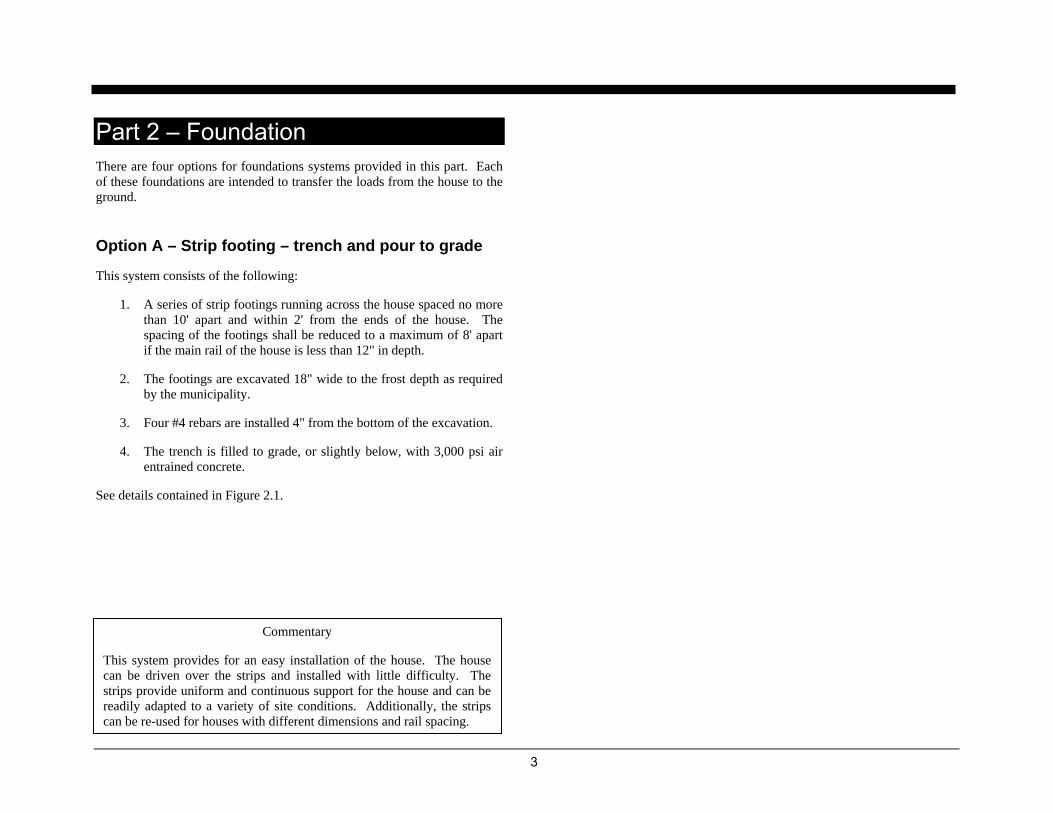
Option A – Strip footing – trench and pour to grade
This system consists of the following:
1. A series of strip footings running across the house spaced no more than 10' apart and within 2' from the ends of the house. The spacing of the footings shall be reduced to a maximum of 8' apart if the main rail of the house is less than 12" in depth.
2. The footings are excavated 18" wide to the frost depth as required by the municipality.
3. Four #4 rebars are installed 4" from the bottom of the excavation.
4. The trench is filled to grade, or slightly below, with 3,000 psi air entrained concrete.
See details contained in Figure 2.1.
Commentary
This system provides for an easy installation of the house. The house can be driven over the strips and installed with little difficulty. The strips provide uniform and continuous support for the house and can be readily adapted to a variety of site conditions. Additionally, the strips can be re-used for houses with different dimensions and rail spacing.

4
Figure 2.1: Option A – Strip footing – trench and pour to grade
5
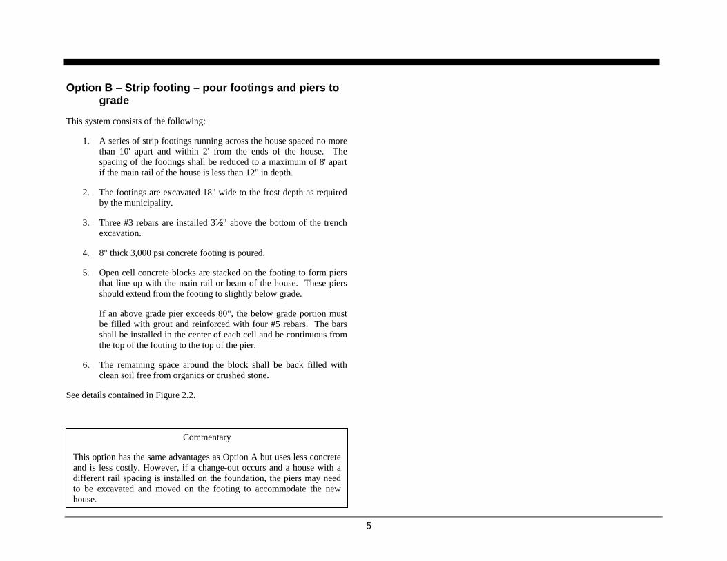
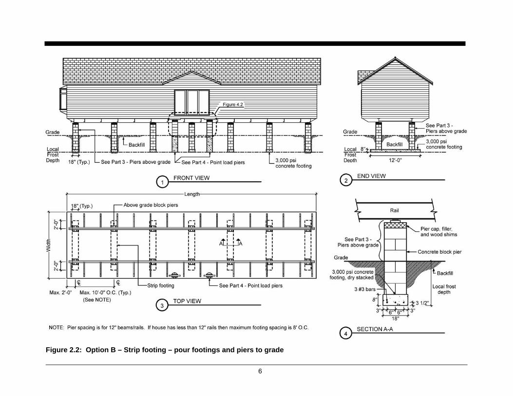
Option B – Strip footing – pour footings and piers to grade
This system consists of the following:
1. A series of strip footings running across the house spaced no more than 10' apart and within 2' from the ends of the house. The spacing of the footings shall be reduced to a maximum of 8' apart if the main rail of the house is less than 12" in depth.
2. The footings are excavated 18" wide to the frost depth as required by the municipality.
3. Three #3 rebars are installed 3½" above the bottom of the trench excavation.
4. 8" thick 3,000 psi concrete footing is poured.
5. Open cell concrete blocks are stacked on the footing to form piers that line up with the main rail or beam of the house. These piers should extend from the footing to slightly below grade.
If an above grade pier exceeds 80", the below grade portion must be filled with grout and reinforced with four #5 rebars. The bars shall be installed in the center of each cell and be continuous from the top of the footing to the top of the pier.
6. The remaining space around the block shall be back filled with clean soil free from organics or crushed stone.
See details contained in Figure 2.2.
Commentary
This option has the same advantages as Option A but uses less concrete and is less costly. However, if a change-out occurs and a house with a different rail spacing is installed on the foundation, the piers may need to be excavated and moved on the footing to accommodate the new house.
6
Figure 2.2: Option B – Strip footing – pour footings and piers to grade
7
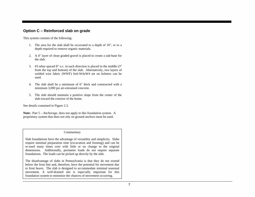
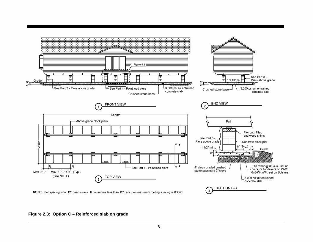
Option C – Reinforced slab on grade
This system consists of the following:
1. The area for the slab shall be excavated to a depth of 10", or to a depth required to remove organic materials.
2. A 4" layer of clean graded gravel is placed to create a sub-base for the slab.
3. #3 rebar spaced 8" o.c. in each direction is placed in the middle (3" from the top and bottom) of the slab. Alternatively, two layers of welded wire fabric (WWF) 6x6-W4xW4 set on bolsters can be used.
4. The slab shall be a minimum of 6" thick and constructed with a minimum 3,000 psi air-entrained concrete.
5. The slab should maintain a positive slope from the center of the slab toward the exterior of the home.
See details contained in Figure 2.3. Note: Part 5 – Anchorage, does not apply to this foundation system. A proprietary system that does not rely on ground anchors must be used.
Commentary
Slab foundations have the advantage of versatility and simplicity. Slabs require minimal preparation time (excavation and forming) and can be re-used many times over with little or no change to the original dimensions. Additionally, perimeter loads do not require separate foundations. The loads can be picked up directly by the slab.
The disadvantage of slabs in Pennsylvania is that they do not extend below the frost line and, therefore, have the potential for movement due to frost heave. The slab is designed to accommodate minimal seasonal movement. A well-drained site is especially important for this foundation system to minimize the chances of movement occurring.
8
Figure 2.3: Option C – Reinforced slab on grade

9
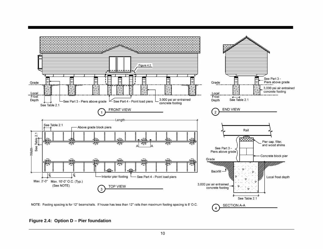
Option D – Pier foundations
The pier foundation system is a series of round or square concrete columns extending from the required frost depth to grade.
1. The piers are located within 2' of the ends of the house and at a maximum spacing along the main rail of the house per Table 2.1.
2. See Part 4, Point Load Piers for locations where perimeter loads exist.
3. The piers are sized based on Table 2.1 and varies with the width of the house, pier spacing and local soil bearing capacity.
4. Piers shall be constructed of 3,000 psi air entrained concrete. Precast concrete piers of adequate size are acceptable.
5. See Part 3 for the requirements of the above grade portion of the piers.
See details contained in Figure 2.4.
Table 2.1: Pier foundation specifications a, b
Soil Bearing Capacity
1,500 psf 2,000 psf 3,000 psf
Hou
se W
idth
Pier Spacing
(ft.)
Load (lbs) o
Dia. (in)
■ Square
(in)
o Dia. (in)
■ Square
(in)
o Dia. (in)
■ Square
(in)
6 4,648 24 22x22 22 20x20 18 16x16 8 6,075 28 24x24 24 22x22 20 18x18
14 ft
.
10c 7,502 30 28x28 26 24x24 22 20x20 6 5,151 26 24x24 22 20x20 18 16x16 8 6,747 30 26x26 26 22x22 20 18x18
16 ft
.
10c 8,344 32 30x30 28 26x26 22 20x20
NOTES: a. Rectangular footings with equivalent areas may be substituted. b. Based on 3,000 PSI concrete. c. 10' pier spacing not allowed if main rail is less than 12" in depth.
Commentary
Pier foundations are the most commonly used type of foundation in the manufactured house community. Piers are easy to install, economical and adapt readily to a variety of site conditions. The disadvantage of using pier foundations is that they are not readily reusable. Once the piers are set for one house, they most likely will not work for a different house. If the owner wants to set another house on the same site, new piers would have to be placed.
10
Figure 2.4: Option D – Pier foundation

11
Part 3 – Piers above grade The following are the requirements for piers to transfer vertical loads from the house rail or beam to the foundation.
Table 3.1: Piers above grade
Height (inches) Pier Requirements1,2, 3
Less than 36"
Except for corner piers, piers shall be constructed of a minimum of 8" by 16" masonry block with the long dimension at right angles to the main rail frame. Blocks shall be dry stacked with cores installed vertically. Piers shall be fully capped to distribute point loads with minimum 4" solid masonry block, solid wood between 2" and 4" nominal thickness, or equivalent. Any additional space can be filled with wood and a pair of 4" x 6" hardwood shims to a combined maximum thickness of 4".
36" to 80" and all corner piers
Piers shall be at least 16" by 16" consisting of interlocking masonry blocks. Dry stacking of the piers is allowed. The piers shall be capped as described above.
Over 80"
Piers shall be constructed in accordance with the provisions of 36" to 80" piers. Additionally the masonry blocks shall be set in mortar and shall be filled solid with grout and reinforced with four continuous #5 bars. One #5 bar shall be placed in the center of each corner cell of hollow masonry block piers.
Notes: 1. Cast-in-place concrete piers meeting the same size and height limitations above may be substituted for piers constructed of masonry blocks.
2. Manufactured piers are allowed as long as they have the capacity listed in Table 2.1 and have a pad (concrete or other material approved by pier manufacturer) installed under them to transfer their load to the foundation system.
3. Oriented strand board (OSB) or plywood are not acceptable as pier caps or spacers. Figure 3.1: Piers above grade

12
This page was intentionally left blank.
13
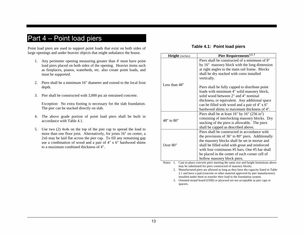
Part 4 – Point load piers Point load piers are used to support point loads that exist on both sides of large openings and under heavier objects that might unbalance the house.
1. Any perimeter opening measuring greater than 4' must have point load piers placed on both sides of the opening. Heavier items such as fireplaces, pianos, waterbeds, etc. also create point loads, and must be supported.
2. Piers shall be a minimum 16" diameter and extend to the local frost depth.
3. Pier shall be constructed with 3,000 psi air entrained concrete.
Exception: No extra footing is necessary for the slab foundation. The pier can be stacked directly on slab.
4. The above grade portion of point load piers shall be built in accordance with Table 4.1.
5. Use two (2) 4x4s on the top of the pier cap to spread the load to more than one floor joist. Alternatively, for joists 16" on center, a 2x6 may be laid flat across the pier cap. To fill any remaining gap use a combination of wood and a pair of 4" x 6" hardwood shims to a maximum combined thickness of 4".
Table 4.1: Point load piers
Height (inches) Pier Requirements1,2, 3
Less than 48"
Piers shall be constructed of a minimum of 8" by 16" masonry block with the long dimension at right angles to the main rail frame. Blocks shall be dry stacked with cores installed vertically. Piers shall be fully capped to distribute point loads with minimum 4" solid masonry block, solid wood between 2" and 4" nominal thickness, or equivalent. Any additional space can be filled with wood and a pair of 4" x 6" hardwood shims to maximum thickness of 4".
48" to 80"
Piers shall be at least 16" by 16" (256 in2) consisting of interlocking masonry blocks. Dry stacking of the piers is allowable. The piers shall be capped as described above.
Over 80"
Piers shall be constructed in accordance with the provisions of 36" to 80" piers. Additionally the masonry blocks shall be set in mortar and shall be filled solid with grout and reinforced with four continuous #5 bars. One #5 bar shall be placed in the center of each corner cell of hollow masonry block piers.
Notes: 1. Cast-in-place concrete piers meeting the same size and height limitations above may be substituted for piers constructed of masonry blocks.
2. Manufactured piers are allowed as long as they have the capacity listed in Table 2.1 and have a pad (concrete or other material approved by pier manufacturer) installed under them to transfer their load to the foundation system.
3. Oriented strand board (OSB) or plywood are not acceptable as pier caps or spacers.

14
Notes: 1. If and when possible (2) 4x4 pressure treated lumber should span both
perimeter piers. If this is not possible, then lumber is to be placed on individual piers spanning no less than two joists.
2. If point load falls directly on outrigger then place point load piers as close as possible to the left or right of the outrigger.
Notes: 1. If and when possible pressure treated lumber should span both perimeter piers.
If this is not possible, then lumber is to be placed on individual piers spanning no less than two joists.
2. If point load falls directly on outrigger then place point load piers as close as possible to the left or right of the outrigger.
Figure 4.2a: Point load piers – Elevation (for joist spacing > 16" o.c.)
Figure 4.2b: Point load piers - Elevation (for joist spacing ≤ 16" o.c.)
Figure 4.1: Point load piers – Section

15
Part 5 – Anchorage Anchorage is necessary on manufactured houses to prevent a house from being displaced by wind forces. The wind creates uplift and lateral forces that act to lift or push the house off the foundation.
The following ground anchor system consists of two parts: lateral anchorage and longitudinal anchorage. The house is anchored to the ground via metal straps attached to ground anchors and tensioned. All anchoring hardware shall be rated to resist 4,725 lbs.
Many proprietary systems also exist that are compatible with the foundation designs in this document. When using a proprietary system ensure that it is rated for HUD Wind Zone I. Any proprietary system must be installed to the manufacturers’ installation instruction. Slab foundations must be constructed with proprietary systems, the use of ground anchors is not allowed.
Lateral anchorage
Anchor requirements are provided in Table 5.1. The figure below illustrates house dimensions required to use this table.
Wind Zone I
Single Section
Anchor Length 30″ or 36″ 48″ or 60″ Stabilizer Plate Width 12″ 17″
Section/Floor Width
Main I-Beam Spacing
Pier Height
Anchor Spacing
Less than 25″ 7.0 11.5 25″ to 39″ 5.5 9.0 Less than 88″
40″ to 48″ 4.5 7.0 Less than 25″ 5.5 9.0 25″ to 39″ 4.0 6.5
Less than 13'
88″ and above
40″ to 48″ ♦ 5.0 Less than 25″ 8.5 13.5 25″ to 39″ 7.0 11.0 Less than 88″
40″ to 48″ 5.5 9.0 Less than 25″ 7.5 12.0 25″ to 39″ 6.0 9.5
13' to 15'
88″ and above
40″ to 48″ 4.5 7.5 Less than 25″ 9.0 14.5 25″ to 39″ 8.0 12.5 Less than 88″
40″ to 48″ 6.5 10.5 Less than 25″ 8.5 13.5 25″ to 39″ 7.0 11.5
More than 15' to 17'
88″ and above
40″ to 48″ 6.0 9.5
Table 5.1: Maximum anchor spacing
Source: This table is an excerpt of the Maximum Anchor Spacing Selector and is included with the permision of the Manufactured Housing Institute (MHI) and the Manufactured Housing Research Alliance (MHRA).
A B C
Figure 5.1: Lateral Anchorage
Pier height D
Anchor spacing Beam spacing
B
A Section or floor width
C
D
16
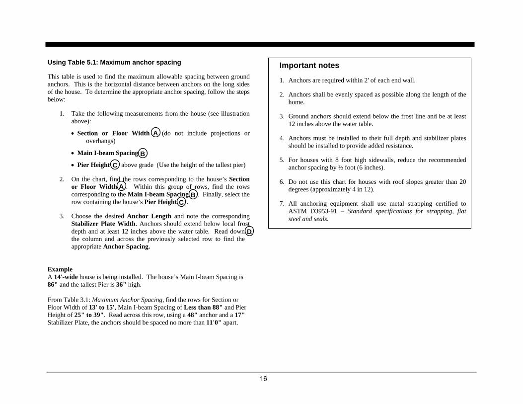
Using Table 5.1: Maximum anchor spacing
This table is used to find the maximum allowable spacing between ground anchors. This is the horizontal distance between anchors on the long sides of the house. To determine the appropriate anchor spacing, follow the steps below:
1. Take the following measurements from the house (see illustration above):
• Section or Floor Width (do not include projections or overhangs)
• Main I-beam Spacing
• Pier Height above grade (Use the height of the tallest pier)
2. On the chart, find the rows corresponding to the house’s Section or Floor Width . Within this group of rows, find the rows corresponding to the Main I-beam Spacing . Finally, select the row containing the house’s Pier Height .
3. Choose the desired Anchor Length and note the corresponding Stabilizer Plate Width. Anchors should extend below local frost depth and at least 12 inches above the water table. Read down the column and across the previously selected row to find the appropriate Anchor Spacing.
Example A 14'-wide house is being installed. The house’s Main I-beam Spacing is 86" and the tallest Pier is 36" high. From Table 3.1: Maximum Anchor Spacing, find the rows for Section or Floor Width of 13' to 15', Main I-beam Spacing of Less than 88" and Pier Height of 25" to 39". Read across this row, using a 48" anchor and a 17" Stabilizer Plate, the anchors should be spaced no more than 11'0" apart.
A
B C
A B
C
D.
Important notes
1. Anchors are required within 2' of each end wall.
2. Anchors shall be evenly spaced as possible along the length of the home.
3. Ground anchors should extend below the frost line and be at least 12 inches above the water table.
4. Anchors must be installed to their full depth and stabilizer plates should be installed to provide added resistance.
5. For houses with 8 foot high sidewalls, reduce the recommended anchor spacing by ½ foot (6 inches).
6. Do not use this chart for houses with roof slopes greater than 20 degrees (approximately 4 in 12).
7. All anchoring equipment shall use metal strapping certified to ASTM D3953-91 – Standard specifications for strapping, flat steel and seals.

17
Longitudinal anchorage
Longitudinal anchors are located on each corner of the house and attached either to factory welded brackets on the I-beam or wrapped around the ends of cross members within 3" the mail rail frame. This attachment to the frame shall be within 72" of the end of the house
Alternate: Site installed brackets can be bolted to the frame per manufacturer’s instructions (must be rated for 3,150 lbs. working load).
Ground anchors shall be a minimum 24" from any sidewall anchor. Ground anchors shall be installed so the straps have a maximum vertical angle of 45° and a maximum horizontal angle of 30°. Distance D from anchor head to connector should be greater than height H from main beam to ground. Anchors shall be installed in line with strap unless approved stabilizer plate is installed.
Figure 5.2 longitudinal anchors
18
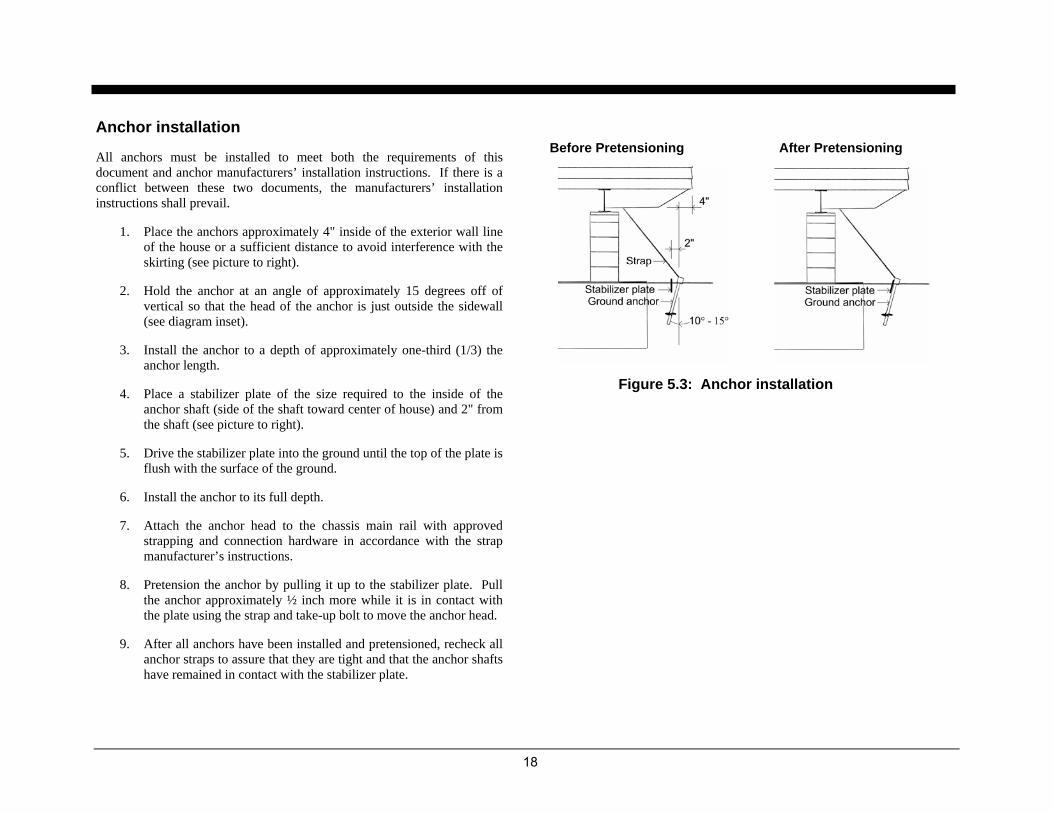
Anchor installation
All anchors must be installed to meet both the requirements of this document and anchor manufacturers’ installation instructions. If there is a conflict between these two documents, the manufacturers’ installation instructions shall prevail.
1. Place the anchors approximately 4" inside of the exterior wall line of the house or a sufficient distance to avoid interference with the skirting (see picture to right).
2. Hold the anchor at an angle of approximately 15 degrees off of vertical so that the head of the anchor is just outside the sidewall (see diagram inset).
3. Install the anchor to a depth of approximately one-third (1/3) the anchor length.
4. Place a stabilizer plate of the size required to the inside of the anchor shaft (side of the shaft toward center of house) and 2" from the shaft (see picture to right).
5. Drive the stabilizer plate into the ground until the top of the plate is flush with the surface of the ground.
6. Install the anchor to its full depth.
7. Attach the anchor head to the chassis main rail with approved strapping and connection hardware in accordance with the strap manufacturer’s instructions.
8. Pretension the anchor by pulling it up to the stabilizer plate. Pull the anchor approximately ½ inch more while it is in contact with the plate using the strap and take-up bolt to move the anchor head.
9. After all anchors have been installed and pretensioned, recheck all anchor straps to assure that they are tight and that the anchor shafts have remained in contact with the stabilizer plate.
Figure 5.3: Anchor installation
Before Pretensioning After Pretensioning

19