mfg12193 artcam software for artists rather than engineers
TRANSCRIPT

MFG12193
ArtCAM Software for Artists Rather Than Engineers Joshua Medina Autodesk/Delcam
Learning Objectives Learn how to create intricate carvings from a photo.
Use simple geometry to create fun 3D models.
Use more complex modeling tools to build a realistic 3D reptile.
See how much time you can save by creating 3D designs from a simple photo.
Create decorative shadow art using lines and 3D designs.
Description Most CAD/computer-aided manufacturing (CAM) tools are designed to enable engineers to design and manufacture products. From the very beginning ArtCAM software has been developed to enable artists and designer to create whatever they can imagine. ArtCAM is used in a variety of sectors from jewelry and coin minting, to the design and manufacture of architectural cornicing and facades. The common theme across these sectors is the desire to produce intricate artistic forms with incredible detail that can then be quickly and easily machined or 3D printed. This class will introduce you to the process that will enable you to take a simple 2D drawing and convert it into a complex decorative relief and machine it.
Your AU Experts
Joshua Medina is an ArtCAM applications engineer from the Salt Lake City Utah office. He began his career in 2004 as an apprentice machinist with a leading Utah manufacturer offering machining and fabrication services to the nuclear, petrochemical, aerospace and mining industries. On completing his training, Joshua spent over two years at Petersen Inc. as a journeyman machinist, before moving to Northrop Grumman, one of the largest defense contractors in the USA. At Northrop Grumman, Joshua worked as an experimental machinist, designing and manufacturing prototype parts and fixtures. Since then he has joined Delcam where he has become proficient in programing using FeatuerCAM and ArtCAM.

ArtCAM Software for Artists Rather Than Engineers
2
Learn how to create intricate carvings from a photo
In this tutorial you will learn the process of creating lines from a imported image and then using the lines to create an intricate carving.
Open the image FLOURISH2.jpeg, and set height to 12” or 300mm if using a metric document.
Click on the Bitmap to Vector icon on the Vector Creation toolbar.
Click on the Reduce Colors button, and drag the slider all the way to the left which changes the value from 32 to 2
Set the primary color to black and click on the Create Vectors button.
Hide the Bitmap by clicking the light bulb in the project panel.
Delete stray vectors located in some of the swirls.

ArtCAM Software for Artists Rather Than Engineers
3
Select all off the vectors by clicking CTRL+A
Once selected click on Toolpaths > New 2D Toolpath > V-Bit Carving from the Toolpaths dropdown menu.
Select a Carving Tool with the following properties. V-Bit 1.25 Inch 130 degree
Click to Define Material and set the Material Thickness to .250” or 6.35mm
Click on the Calculate Now button.
Once calculated click on Toolpaths > Relief Simulation > Simulate Toolpath from the Toolpaths dropdown menu.
Use simple geometry to create fun 3D models.
This Tutorial will show you an all-around view of ArtCAM. This will give an overview on the Shape Editor, Vector Creation, Node Editing, Texture Relief, the Clipart Library and a basic 3D Toolpath.

ArtCAM Software for Artists Rather Than Engineers
4
Shape Editor
In this section you will learn basic shape creation using the Shape Editor tool.
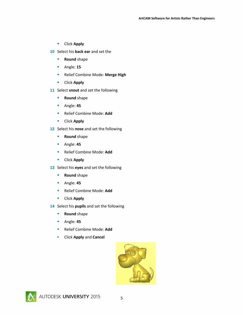
1 Open Dexters Backyard.art
2 Click on the 3D View Tab to changes over to the 3D view
3 If the Dog vectors are not visible click Toggle Vector Visibility
4 Click on View Top
5 Select the vector outlining the dog’s body and open the Shape Editor
6 Set the following in the Shape Editor page
Round shape
Angle: 45
Relief Combine Mode: Add
Click Apply
7 Select his back leg and set the following in the Shape Editor
Round shape
Angle: 45
Relief Combine Mode: Add
Click Apply
8 Select his tail and set the following
Round shape
Angle: 45
Relief Combine Mode: Merge High
Click Apply
9 Select his front ear and set the following
Round shape
Angle: 10
Relief Combine Mode: Add
ArtCAM Software for Artists Rather Than Engineers
5
Click Apply
10 Select his back ear and set the
Round shape
Angle: 15
Relief Combine Mode: Merge High
Click Apply
11 Select snout and set the following
Round shape
Angle: 45
Relief Combine Mode: Add
Click Apply
12 Select his nose and set the following
Round shape
Angle: 45
Relief Combine Mode: Add
Click Apply
13 Select his eyes and set the following
Round shape
Angle: 45
Relief Combine Mode: Add
Click Apply
14 Select his pupils and set the following
Round shape
Angle: 45
Relief Combine Mode: Add
Click Apply and Cancel

ArtCAM Software for Artists Rather Than Engineers
6
Vector Creation, Node Editing and Texture Relief
This section will show you some basic Vector Creation as well as Node Editing and the Texture Relief tool
15 Open the Create Rectangle tool
16 Type the following dimensions into the rectangle tool
Width: 2.5”
Height: 0.5”
X: 4.5”
Y: 5”
Create and Cancel
17 Open the Create Circles tool
18 Type the following dimensions into the Circle Creation tool
X: 5.75”
Y: 5.25”
Radius: 0.3”
Create
19 Change the following in the Circle Creation tool
X: 5.75”
Y: 4.75”
Radius: 0.35”
Create and Cancel
20 Hold the Shift key on the keyboard and select the two circles you have created, release the shift key and press and hold the Ctrl key to copy now drag the circles to the other side of the rectangle
ArtCAM Software for Artists Rather Than Engineers
7
21 Select all four circles and the rectangle by dragging a window over them (Click and hold the mouse button down and drag a window over the shapes).
22 Click on the Weld Vectors tool
23 Press F12 on your keyboard, Note this is a short key for the Shape Editor
Round shape
Angle: 45
Relief Combine Mode: Add
Apply and Cancel
24 Open the Rectangle tool again and type in the following dimensions
Width: 6”
Height: 5”
X: 6”
Y: 10”
Create and Cancel
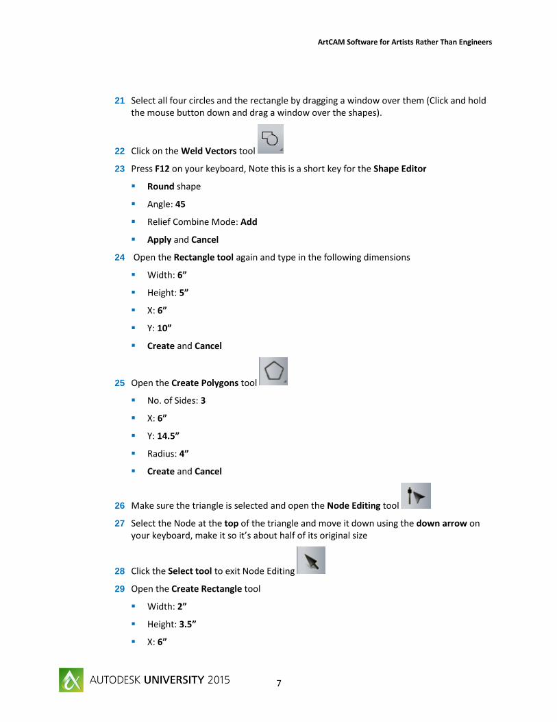
25 Open the Create Polygons tool
No. of Sides: 3
X: 6”
Y: 14.5”
Radius: 4”
Create and Cancel
26 Make sure the triangle is selected and open the Node Editing tool
27 Select the Node at the top of the triangle and move it down using the down arrow on your keyboard, make it so it’s about half of its original size
28 Click the Select tool to exit Node Editing
29 Open the Create Rectangle tool
Width: 2”
Height: 3.5”
X: 6”

ArtCAM Software for Artists Rather Than Engineers
8
Y: 9”
Create and Cancel
30 Make sure the Rectangle is selected and press N on your keyboard, Note this is a short key for Node Editing
31 Hover the cursor over the top span of the rectangle, the mouse should be white with a little black line beside it when over the span.
Right click on the span and click on Convert Span to Arc [A]
Press N on your keyboard to exit Node Editing
32 Select the rectangle section of the house and press F12
Plane
Start height: 0.5”
Relief Combine Mode: Add
Apply
33 Select the triangle
Plane
Start Height: 0.75”
Relief Combine Mode: Merge High
Apply and Cancel
34 Make sure that the triangle is still selected and open the
Texture Relief tool
35 Set up the Texture relief page as follows
Selected Vector
Pyramid
Size: 0.25”
ArtCAM Software for Artists Rather Than Engineers
9
Z Height: 0.065”
O%: 50
Add and Close
36 Select the Vector representing the door and click Zero Inside Vector
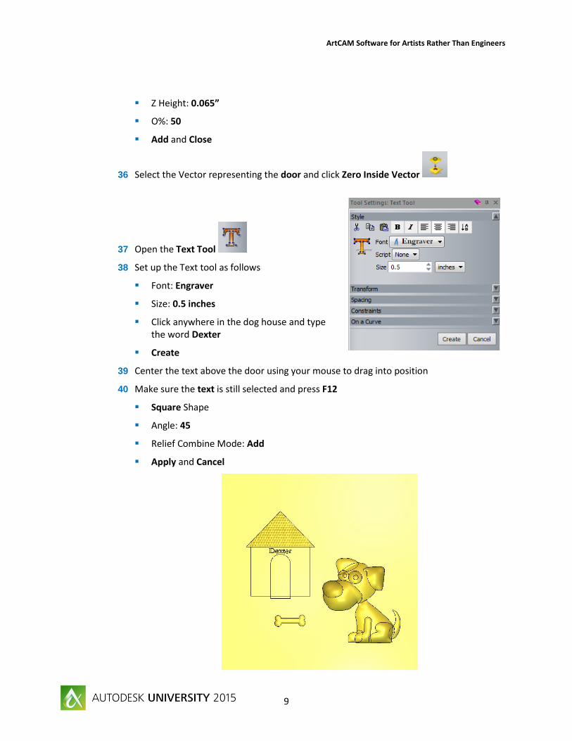
37 Open the Text Tool
38 Set up the Text tool as follows
Font: Engraver
Size: 0.5 inches
Click anywhere in the dog house and type the word Dexter
Create
39 Center the text above the door using your mouse to drag into position
40 Make sure the text is still selected and press F12
Square Shape
Angle: 45
Relief Combine Mode: Add
Apply and Cancel
ArtCAM Software for Artists Rather Than Engineers
10
Clipart Library
The Clipart Library contains over 500 reliefs, free for you to use with your purchase of ArtCAM.
41 Open the Clipart Library
Select the Greenery folder and find the Mountains2
Click on it to bring it into the model
Position it to the right of the dog house and just above the dog’s head
Paste the Mountain down by clicking Paste in the Transform window
Note when clipart is brought into the model this will stay blue until it is pasted down when pasted it will turn gold like the rest of the model.
If you accidently deselect the clipart you will close the transform tool, to open Transform
select the clipart and click on the Transform tool or you can press T on your keyboard
42 Find the Grass Brush in the Greenery folder
Click on it to bring this into the model
Position this in the bottom left hand corner no higher than the bone
Press and hold the Ctrl Key and drag the clipart to the right and slightly down to make a copy of it
Do this another two times so the grass runs across the bottom of the model
Shift select all pieces of grass and Paste
43 Click the drop menu in the Clipart library to change folders and find Emboss
Click on Tree5
Drag this to the top left just above the doghouse
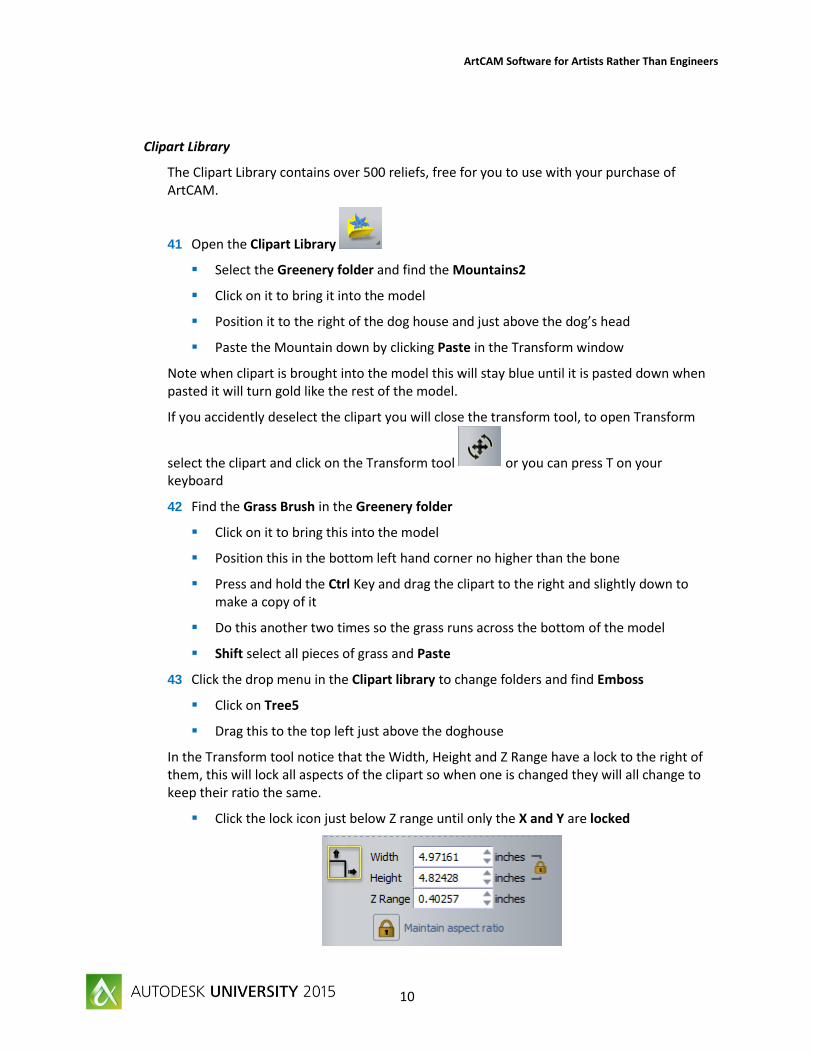
In the Transform tool notice that the Width, Height and Z Range have a lock to the right of them, this will lock all aspects of the clipart so when one is changed they will all change to keep their ratio the same.
Click the lock icon just below Z range until only the X and Y are locked

ArtCAM Software for Artists Rather Than Engineers
11
Grab the bottom right red Node to resize the tree so the Width is about 7.5 inches
Press and hold Ctrl and drag a copy down slightly and to the right
Make another copy and drag this to the left of the doghouse, make it slightly larger about 9.75 inches in width
Move your curser outside the clipart resizing window until the cursor turns into a circular arrow, click, hold and drag to rotate the tree about -3 degrees you will see the angle in the transform page.
Shift select all blue clipart and press Enter on the keyboard, note this is a shortcut for pasting clipart
Toolpath Creation
This section will show you a basic toolpath and simulation.
44 In the Project Tree click on Toolpath to expand the toolpath window
45 In the 3D Toolpaths section click on Create Machine Relief
Toolpath
46 In Finishing Options, Click To Select
In the Tool Database, expand Inch Tools, followed by Wood or Plastic
In the 3D Finishing folder and select the Ball Nose 1/8 Inch and
Click Select
ArtCAM Software for Artists Rather Than Engineers
12
47 Expand the Safe Z section
Safe Z: 1
Home X: 0
Home Y: 0
Home Z: 1
48 Click To Define Material
Material Thickness: 1.75”
Material Z Zero: On top
Bottom Offset: 0.25”
Ok
49 Leave everything else as default and click Calculate now, when calculation is complete close the toolpath window
50 Right click on Toolpaths in the Project Tree and click Simulate All Toolpaths
Click the Simulate Toolpath button.
This will display the finished product showing what the toolpath will look like machined into a fake piece of material.
The Tutorial is now complete!
ArtCAM Software for Artists Rather Than Engineers
13
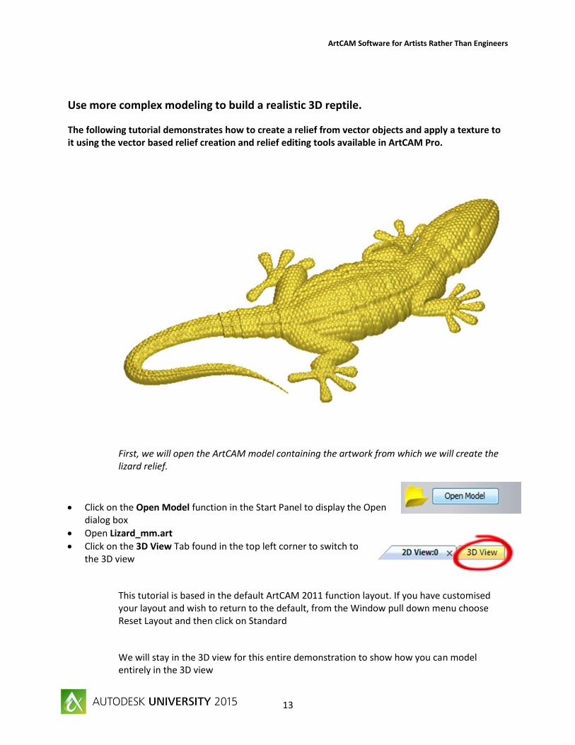
Use more complex modeling to build a realistic 3D reptile.
The following tutorial demonstrates how to create a relief from vector objects and apply a texture to it using the vector based relief creation and relief editing tools available in ArtCAM Pro.
First, we will open the ArtCAM model containing the artwork from which we will create the lizard relief.
Click on the Open Model function in the Start Panel to display the Open dialog box
Open Lizard_mm.art
Click on the 3D View Tab found in the top left corner to switch to the 3D view
This tutorial is based in the default ArtCAM 2011 function layout. If you have customised your layout and wish to return to the default, from the Window pull down menu choose Reset Layout and then click on Standard
We will stay in the 3D view for this entire demonstration to show how you can model entirely in the 3D view

ArtCAM Software for Artists Rather Than Engineers
14
The following artwork appears in the 2D and 3D Views:
The *.art file that you have opened is a model previously created in ArtCAM Pro. The model contains vector objects that will be used to create the different parts of a lizard.
Some of the vector objects will be used as drive rails, others as cross-sections, from which shapes will be swept. Other vector objects will only have shape attributes applied to them, from which a shape will then be calculated and combined with the relief.
Click on the Reset Relief button in the Relief Editing Toolbar, to delete the relief that was saved as part of the Lizard.art model
Toggle Vector Visibility to show vectors on 3D View
Relief Creation
First we will create the main body of the lizard using the three cross-sections drawn in the top-left corner of the model and the pairs of vector objects that represent each part of the lizard. As you will see, almost the entire lizard is modelled using a process where a three-dimensional shape is created by sweeping a cross-section between two vectors, referred to as drive rails. This process is called a two-rail sweep.
We will start with the lizards' tail.
Click on the Two Rail Sweep button in the Relief Creation Toolbar to display the Two Rail Sweep panel
Select the vector representing the left-edge of the tip of the lizard's tail
In the Select Control Vectors area, click on the Select button for the Top Drive Rail
ArtCAM Software for Artists Rather Than Engineers
15
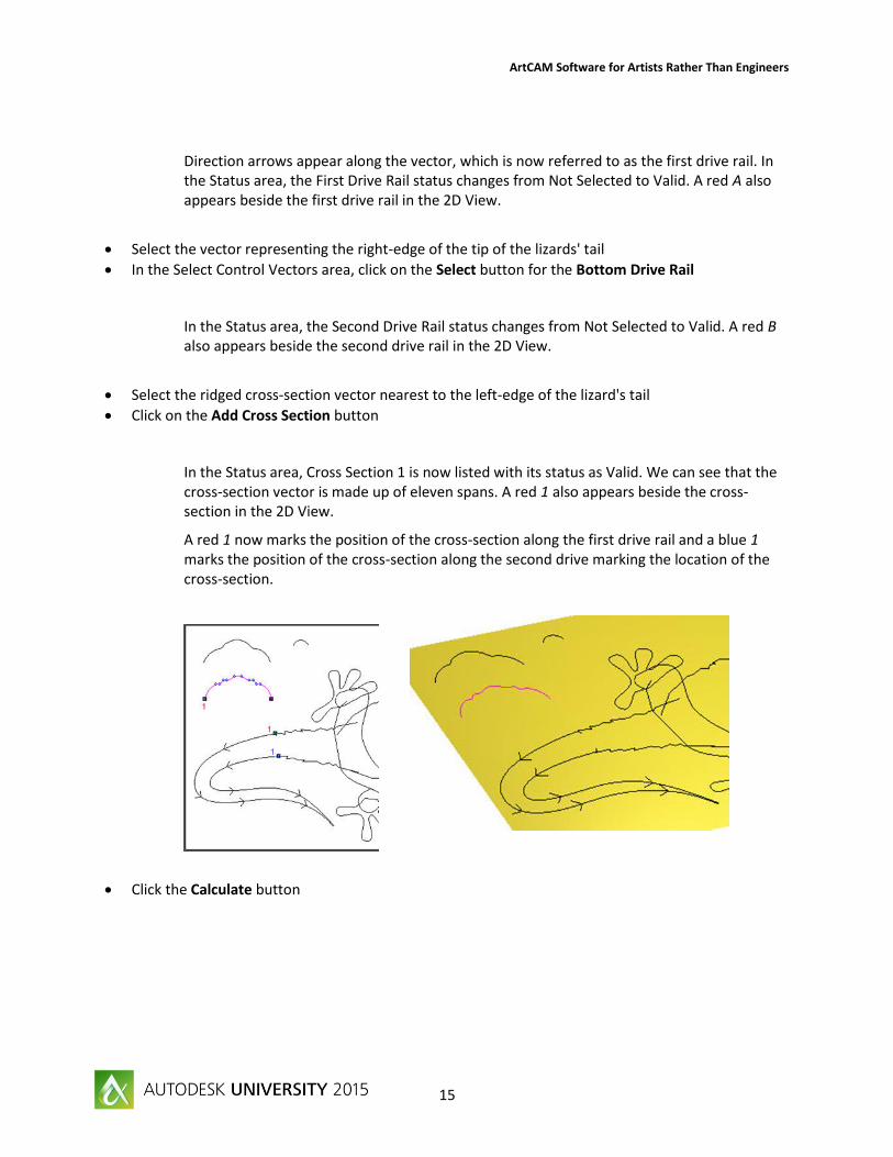
Direction arrows appear along the vector, which is now referred to as the first drive rail. In the Status area, the First Drive Rail status changes from Not Selected to Valid. A red A also appears beside the first drive rail in the 2D View.
Select the vector representing the right-edge of the tip of the lizards' tail
In the Select Control Vectors area, click on the Select button for the Bottom Drive Rail
In the Status area, the Second Drive Rail status changes from Not Selected to Valid. A red B also appears beside the second drive rail in the 2D View.
Select the ridged cross-section vector nearest to the left-edge of the lizard's tail
Click on the Add Cross Section button
In the Status area, Cross Section 1 is now listed with its status as Valid. We can see that the cross-section vector is made up of eleven spans. A red 1 also appears beside the cross-section in the 2D View.
A red 1 now marks the position of the cross-section along the first drive rail and a blue 1 marks the position of the cross-section along the second drive marking the location of the cross-section.
Click the Calculate button

ArtCAM Software for Artists Rather Than Engineers
16
Now we will combine the base of the tail with the tip of the tail that we have already created.
The Two Rail Sweep function should still be open. If you closed it, re-open it now.
Click the Reset button on the Two Rail Sweep panel
Select the vector representing the left-edge of the lizard's tail-base
In the Select Control Vectors area, click on the Select button for the Top Drive Rail
Select the vector representing the right-edge of the lizard's tail-base
In the Select Control Vectors area, click on the Select button for the Bottom Drive Rail
Select the ridged cross-section vector nearest to the lizard's tail
Click on the Add Cross Section button

ArtCAM Software for Artists Rather Than Engineers
17
In the Combine area, click to select the Highest radio button
Click the Calculate button
We can now create the lizard’s body.
Click the Reset button on the Two Rail Sweep panel
Select the vector representing the left-edge of the lizard's body
In the Select Control Vectors area, click on the Select button for the Top Drive Rail
Select the vector representing the right-edge of the lizard's body
In the Select Control Vectors area, click on the Select button for the Bottom Drive Rail
ArtCAM Software for Artists Rather Than Engineers
18
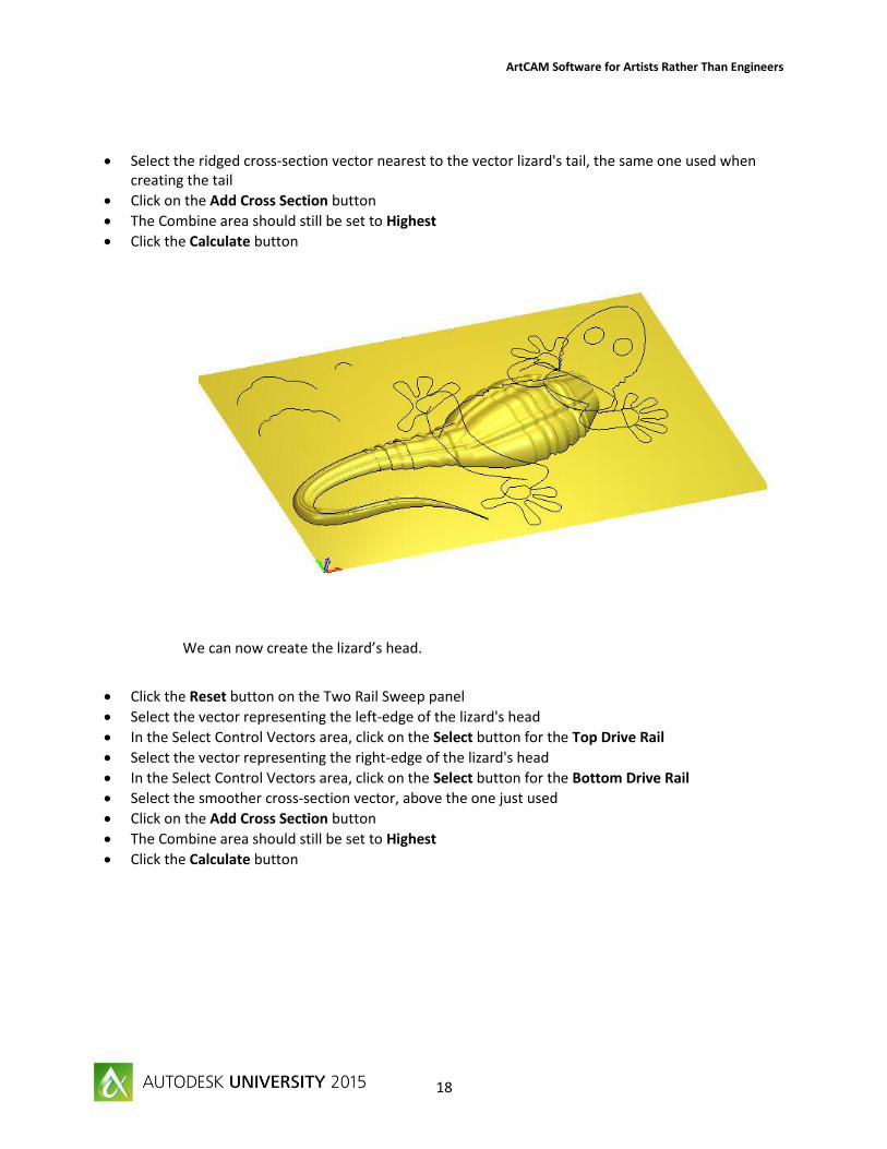
Select the ridged cross-section vector nearest to the vector lizard's tail, the same one used when creating the tail
Click on the Add Cross Section button
The Combine area should still be set to Highest
Click the Calculate button
We can now create the lizard’s head.
Click the Reset button on the Two Rail Sweep panel
Select the vector representing the left-edge of the lizard's head
In the Select Control Vectors area, click on the Select button for the Top Drive Rail
Select the vector representing the right-edge of the lizard's head
In the Select Control Vectors area, click on the Select button for the Bottom Drive Rail
Select the smoother cross-section vector, above the one just used
Click on the Add Cross Section button
The Combine area should still be set to Highest
Click the Calculate button

ArtCAM Software for Artists Rather Than Engineers
19
We are now ready to create the lizard's legs in the same way as its head and body.
Click the Reset button on the Two Rail Sweep panel
Select the vector object representing the lower part of the lizard's back legs
In the Select Control Vectors area, click on the Select button for the Top Drive Rail
Select the upper part of the lizard's back legs
In the Select Control Vectors area, click on the Select button for the Bottom Drive Rail
Select the smallest of the cross-section vectors, the semi circle
Click on the Add Cross Section button

ArtCAM Software for Artists Rather Than Engineers
20
The Combine area should still be set to Highest
Click the Calculate button
Click the Reset button on the Two Rail Sweep panel
Select the vector object representing the lower part of the lizard's front legs
In the Select Control Vectors area, click on the Select button for the Top Drive Rail
Select the upper part of the lizard's front legs
In the Select Control Vectors area, click on the Select button for the Bottom Drive Rail
Select the same semi circle cross-section vector
Click on the Add Cross Section button
The Combine area should still be set to Highest
Click the Calculate button
Click on the Close button

ArtCAM Software for Artists Rather Than Engineers
21
The lizards' feet can be created directly from the vector objects representing their outline. This is done by applying shape attributes to the vectors, and then combining these shapes with the current relief.
Hold down the Shift key on your keyboard, and then click on each of the four vector objects representing the lizards' feet
Press the F12 key on your keyboard to display the Shape Editor
ArtCAM Software for Artists Rather Than Engineers
22
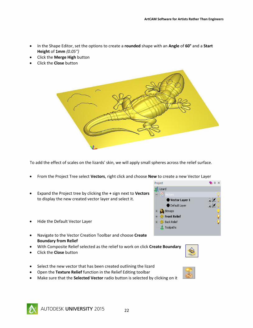
In the Shape Editor, set the options to create a rounded shape with an Angle of 60° and a Start Height of 1mm (0.05”)
Click the Merge High button
Click the Close button
To add the effect of scales on the lizards' skin, we will apply small spheres across the relief surface.
From the Project Tree select Vectors, right click and choose New to create a new Vector Layer
Expand the Project tree by clicking the + sign next to Vectors to display the new created vector layer and select it.
Hide the Default Vector Layer
Navigate to the Vector Creation Toolbar and choose Create Boundary from Relief
With Composite Relief selected as the relief to work on click Create Boundary
Click the Close button
Select the new vector that has been created outlining the lizard
Open the Texture Relief function in the Relief Editing toolbar
Make sure that the Selected Vector radio button is selected by clicking on it

ArtCAM Software for Artists Rather Than Engineers
23
The texture will be applied to all areas of the relief inside of the vector, which now outlines the entire lizard.
Click on the Sphere radio button to select it as the texture shape
In the Sizing area, type 5mm ( 0.2”) in the Size box and 1mm (0.05”) in the Z Height box
In the Spacing area, type 50 in the O% box
Click the Add button
Click the Close button

ArtCAM Software for Artists Rather Than Engineers
24
Finally, we will add the lizards' eyes to the relief using the same process that was used to create the feet.
Show the Default Vector Layer
Hold the Shift key down on your keyboard, and then click on the vector objects representing the lizards' eyes
Press the F12 key on your keyboard to display the Shape Editor
In the Shape Editor, set the options to create a rounded shape with an Angle of 80° and a Start Height of 12mm (0.5”)
Click on the Merge High button, followed by the Close button
Toggle Vector Visibility to hide the vectors in the 3D View
This tutorial is complete!
See how much time you can save by creating 3D designs from a simple photo.
In this tutorial we will learn how to make a 3D file from an imported image. We will also smooth out the 3D image and apply toolpath to the finished 3D model.
Open the fountain_building.jpeg and give it a size of 8” or 200mm if using a metric document. Also give it a height of .150” in Z or 4mm for a metric document.
Click on the 3D view button.

ArtCAM Software for Artists Rather Than Engineers
25
You will see that ArtCAM has created a 3D file from the imported image.
Click on the Smooth Relief button.
We are going to change the Smoothing Passes from 1 to 3 and click the Apply button. This will clean up some of the pixilation created from the image.
Now we are ready to apply toolpaths to the 3D file.
Click on Toolpaths > New 3D Toolpath > Machine Relief from the Toolpaths dropdown menu
ArtCAM Software for Artists Rather Than Engineers
26
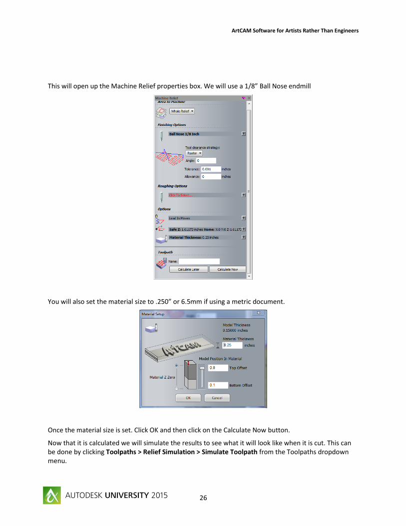
This will open up the Machine Relief properties box. We will use a 1/8” Ball Nose endmill
You will also set the material size to .250” or 6.5mm if using a metric document.
Once the material size is set. Click OK and then click on the Calculate Now button.
Now that it is calculated we will simulate the results to see what it will look like when it is cut. This can be done by clicking Toolpaths > Relief Simulation > Simulate Toolpath from the Toolpaths dropdown menu.

ArtCAM Software for Artists Rather Than Engineers
27
This tutorial is complete.