mftr-2100 medium range tspi & debris radar - techbel€¦ · mftr-2100 medium range tspi &...
TRANSCRIPT

Weibel Scientific
Solvang 30 3450 Allerød
Denmark
MFTR-2100 Medium Range TSPI & Debris Radar
43 & 40 dB High Performance Systems

MFTR-2100/40 & MFTR-2100/43Specification
2/22
TABLE OF CONTENT
1. INTRODUCTION ................................................................................................................................ 3 2. SYSTEM OVERVIEW ........................................................................................................................ 5
2.1 The function of the sub-modules ......................................................................... 6
2.1.1 Main System parts ................................................................................... 6 2.1.2 Options and Accessories ........................................................................ 9
2.2 Technical Speciations ....................................................................................... 11
2.2.1 Technical Specifications: Main parts ..................................................... 11 2.2.2 Technical Specifications: Options ......................................................... 16
2.3 Data output ........................................................................................................ 20
3. TRACKING MODES ........................................................................................................................ 21
MFTR-2100/46 to the left and MFTR-2100/40 to the right at Weibel Test Range in Denmark

MFTR-2100/40 & MFTR-2100/43Specification
3/22
1. INTRODUCTION The MFTR-2100 Multi Frequency Trajectory Radar system is based on a MFDR-2100 X-band continuous wave Multiple Frequency Doppler Radar, mounted on the high performance AP-2100 Antenna Pedestal.
The system measures and computes directly in real-time for Multiple Objects:
Slant range
Azimuth and Elevation angles
3-D trajectory
Radial velocity
All measurements are Time synchronized to IRIG-B; other time references are available (e.g. GPS)
The range, angles and velocity measurements are based entirely on spectrum analysis and digital signal processing. This enables the system to measure on all types of objects:
Rocket launches
Missiles
Re-entry vehicles
Aircraft, drones and towed-targets
Projectiles of all types and calibres
Base bleed and rocket assisted projectiles
APFSDS and tracer projectiles
Intercepts - Kill assessments
The system is based on X-band frequency in order to ensure:
High accuracy
Compact system
High mobility
High range performance
Operation in all weather conditions
Insensitivity to ionized gases and rocket exhaust plumes
The Multiple Frequency CW/FM-CW Doppler radar technique gives the following advantages:
Optimum MTI (Motion Target Indicator) based on 100% duty cycle on CW Doppler
Optimal range accuracy
Optimal velocity accuracy
Optimal angle accuracy
Continuous measurement - 100% duty cycle
High range resolution in FM-CW mode (High bandwidth)
No minimum object size
Low elevation measurement
Ideal for RCS measurement
The MFTR-2100 is based on the Weibel Azimuth & Elevation Tracking Radar System in operation for more than 20 years all over the world. The radar antenna is based on the well know Weibel MSL antenna family, the AP-2100 Antenna Pedestal is based on the TC-700i Tracking Controller and the RTP-2100 is based on the W-1000/W-2100/RP-2100 family.
The MFTR-2100 is based on state of the art radar technologies. Transmitting and receiving antennas are micro strip array antennas and all components in the system are entirely solid state. A rugged mechanical system design and modern electronic design ensures high reliability and resistance to weather, vibrations, and blast.
The MFDR antennas have a variable beam width from 10° x 10° to e.g. 0.5° x 0.5° with automatic or manual switching. The smallest beam is dependent on the actual antenna.

MFTR-2100/40 & MFTR-2100/43Specification
4/22
The next generation antennas will incorporate higher LFM bandwidth (100, 200 and 500 MHz) for radar imaging, and separation of closely spaced objects. This high LFM (Linear Frequency Modulation) bandwidth together with unambiguous Doppler makes the MFTR-2100 series even more unique.
The next generation antenna will also incorporate electronic beam steering using both beam time slicing and beam slicing and in this way cover a larger special area for multi object tracking and debris characterisation than the pencil beam covers today (down to 0.5° x 0.5°). Possible beam coverage will at present be10° x 10°, 20° x 20° and 40° x 40°.
The software package for the system is constantly developed and improved to meet new requirements from our customers and to incorporate new features.
MFTR-2100/40 & CA-2100/40 on MTB-2100/40

MFTR-2100/40 & MFTR-2100/43Specification
5/22
2. SYSTEM OVERVIEW
The MFTR-2100 system consists of:
MFDR-2100 Multi Frequency Doppler Radar antenna
OM-2124D Dual Frequency MF-CW and FM-CW Oscillator
ASM-2100 Additional Sensor Mount
AP-2100 Antenna Pedestal
CA-2100 Continuous Azimuth (Optional)
MTB-2100/40 Trailer (Optional)
RTP-2100 Real Time Processor
RTDS-2100 Real Time Data Storage
RTD-2100 Real Time Display (Optional)
IC-2100 Instrumentation Controller with WinTrack software
TR-2100 200 / 400 VAC Transformer (Optional)
BSC-2100 Bore sight Camera with zoom optics.(Optional)
IR cameras several models supported (Optional)
MC-100 Monopulse Calibration Device (Optional)
CU-2100 Cooling Unit – Water based forced transmitter Cooling (Optional)
VT-2100 Video Tracker (Optional)
OPS-2100 20 Operator Shelter (Optional)
MCS-2100 Motion Compensation System (Optional)
Several different configurations are available. The main difference is
the antenna gain and thereby antenna size and associated Antenna Pedestals. The following antennas are available today: 35, 37, 40, 43, 46 and 49 dB antennas This specification only covers the 40 and 43 dB antenna: MFDR-2100/40 and MFDR-2100/43 and associated pedestal: AP-2100/40.
The MFDR-2100/xx antenna is mounted on the AP-2100/xx Antenna Pedestal with the transmitter on the left side and receiver on the right side as seen from the front.
The optics – visual and/or IR camera - are mounted on the ASM-2100 Additional Sensor Mount
The AP-2100/xx may be mounted on the optional CA-2100/xx Continuous Azimuth base.
The optional MCS-2100 Motion Compensation System can be placed inside the Antenna pedestal base
The AP-2100/40 with antenna is placed on the optional MTB-2100/40 trailer, on a optional custom designed trailer, on a permanent installation or on a ship. The Oscillator Module is placed on the rear of the receiver, and the antenna power supply is placed on the rear of the pedestal. The RTP-2100 Real Time Processor is either mounted in the platform base (trailer) in an sealed air-conditioned environment or in the operator room/shelter. The RTP-2100 is controlled from the IC-2100 Instrumentation Controller equipped with the WinTrack operator and control software. The RTDS-2100 and optional RTD-2100 are mounted in the operator shelter together with the IC-2100 Instrumentation Controller.
MFDR-2100/40 Antenna With Radome

MFTR-2100/40 & MFTR-2100/43Specification
6/22
2.1 The function of the sub-modules
MFDR-2100/xx
RTP-2100
External
Storage
RTDS-2100
AP-2100/xx
AC input
Platform motion
IC-2100
AC line
<- Digitized Doppler data
<-Encoder data
Command Position->
TSPI data->
Status msg
Antenna Control
Commands.
Oscillator in
IMU
(SEANAV)
GPS
receiver
System Control
MOT TSPI data->
AntPSUAC line
OM-21XX
Optical
Port
IRIG-B in
MFTR-2100 system overview
Outdoor
Control
Console
Camera
Control
Warning
Device
Output
Optical Fiber
RS-422
1 Gbit optical Link
Ethernet
Ethernet
Antenna
Control
Antenna
ControlDoppler
Out
Master/Slave I/O
RS-422 or Ethernet
CA-2100/xx
RTD-2100
Ethernet
MCS-2100
Optical Port
BSC-2100
VT-2100
CU-2100/xx
2.1.1 Main System parts
MFDR-2100/40 & 43: The 40 & 43 dB antenna consists of one transmitter module and one receiver
module. All microwave components including micro-controllers and DC-DC converters are located in the antenna.
The transmitter transmits the two frequencies F1 and F2 simultaneously.
The receiver receives the reflected signals (F1 and F2) and generates 4 I/Q channels corresponding to F1 and 4 IQ channels corresponding to F2.
The 43 dB transmitting and receiving antenna consists of 64 (32 for the 40 dB) micro-strip antennas each with a 10°x10° opening angle.
The advanced Weibel Power Pack microwave transmit unit (HPA) is used in the transmitter with built in power supply and processor for optimum performance, redundancy, control, diagnostics and maintainability. The Power Pack design eliminates the need for re-calibration of the transmitter if it ever needs repair.
The Power Pack design in the transmitter also includes power detectors with feedback in order to operate with constant output power for RCS measurements.
A filter low noise amplifier (LNA) is connected to each micro-strip antenna in the receiver giving a noise figure of less than 3 dB. The filtering of high power pulsed

MFTR-2100/40 & MFTR-2100/43Specification
7/22
radars in the front end prevents the Doppler signal from being distorted in the input LNA.
Both transmitter and receiver include micro-controllers to control and diagnose the HPA’s, LNA’s, base band amplifiers, and the Oscillator Module. The micro-controller also reads all voltages, currents, and temperatures.
Both transmitter and receiver are protected with a fiberglass radome for optimum weather protection; the advanced sandwich structure of the radome ensures minimum signal reduction due to rain, snow, etc on the radar surface.
All antenna functions are controlled automatically by the RTP or manually by the operator from the Operator Console including the variable opening angle.
OM-2124D & OM-2136D: The Oscillator Module (OM)generates two transmitting frequencies F1 and F2.
The two frequencies are transmitted simultaneously.
! F1 is pure CW and is used for angle tracking and accurate unambiguous Doppler measurement.
! F2 operates either in jittering CW or FM-CW (Frequency-Modulated CW) .
The jittering CW is used to measure the range very accurately using the MF-CW (Multi- Frequency CW) principle.
The FM-CW is used to measure and angle track targets with low radial velocity (less than 5-20 m/s depending on external conditions) or to measure on multiple targets with little radial velocity separation.
The status and the control of the OM is displayed and controlled from the Operator Console.
In addition to the standard low noise version (OM-2124D), the Oscillator Module is also available in an Ultra Low Noise version (OM-2136D) for low elevation and long range applications.
AP-2100/40: The AP-2100/40 Antenna Pedestal (AP) is a very ruggedized mount and accurate positioner for the MFDR-2100/40 and MFDR-2100/43 antenna.
The AP-2100 has built-in extremely accurate tilt sensors enabling the system to compensate for the uncertainty in the mechanical leveling.
The elevation axis has two independent positioning systems, one for the transmitting antenna and the other for the receiving antenna.
The azimuth axis has one positioning system. The azimuth positioning system comes in two versions:
! Non Continuous: Based on a very accurate gear/motor system.
! Continuous, CA-2100 option: Based on a large turntable bearing with slip-ring/rotary joint.
All positioning systems are controlled from the AP-2100 main processor. The main processor handles all tasks including real-time data exchange with RTP-2100 and other instrumentation, azimuth and elevation servo-algorithms, motor control and reads all sensors such as encoders, tilt, temperatures, voltages, currents, motor status, etc.
PS-5000: The PS-5000 is a 5 KWatt power supply with 48 VDC nominal output to MFDR-2100 antenna and either with 3~N 200 VAC or 3~N 400 VAC input.
RTP-2100: The Real Time Processor (RTP) is the center of the MFTR and interfaces to Antenna, Oscillator Module, AP-2100, Instrumentation Controller, Real Time Data Storage, Real Time Display, Video Tracker, Motion Compensation System, real time pointing of other systems or real time data from other systems for pointing of the AP-2100.

MFTR-2100/40 & MFTR-2100/43Specification
8/22
The RTP receives the digitized Doppler signals from the AP-2100 via the high speed optical interface.
The RTP is controlled from the Instrumentation Controller both during set-up and in real-time measurement and acquisition.
The RTP incorporates advanced multi-object tracking software (MOT). The MOT calculates the velocity, range, and angles for multiple objects in the radar beam in real-time. The objects are grouped into one main track and secondary tracks.
The RTP receives the azimuth and elevation encoder position from AP-2100 and uses this together with the azimuth and elevation error angles from the main track or from the optional VT-2100 to calculate angle of sight to the main object. From this, the RTP generates the desired mount position and transmits it to the AP-2100. The AP-2100 includes all software and hardware to control the movement of the mount very accurately.
The RTP transmits in real-time the measured velocity, range, and angles for each track (object) to the Instrumentation Controller. The Instrumentation Controller displays the main and secondary tracks in real-time.
Switching between objects is either automatically performed by the RTP or commanded by the operator.
IC-2100: The Instrumentation Controller (IC)is based on a 19" rack mounted High Performance PC with color monitor and command panel. The IC-2100 is running WinXP/Vista and the Display, Control, Diagnostic and Processing Software - WinTrack. The IC is equipped with high speed Ethernet for communication to the RTP.
WinTrack: The Control, Diagnostic and Processing Software is the main operator interface both during set-up, mission, and post-processing. The software accomplishes the following main tasks:
Mission planning
RTP control, set-up, and diagnostics
AP control, set-up, and diagnostics
MFDR Antenna control, set-up, and diagnostics
OM control set-up, and diagnostics
User selectable real time display of multiple tracks (objects) - can include:
- A-scope, DTI, Velocity history, Range history, Elevation history, Azimuth history, Ground track, Altitude track, Bore sight, Radar plot, Numerical, System, and Track status
Real-time track selection and real-time control of IC, RTP, AP, MFDR, and OM
Play back
Off-line processing - Multi object processing (MOT) - Target motion analysis (Spin) - Coordinate transformation - Curve fitting - Trajectory Modelling (PM and MPM) - Output data generation and presentation

MFTR-2100/40 & MFTR-2100/43Specification
9/22
RTDS-2100: The Real Time Data Storage System is based on 19" rack mounted High Performance Pc with a RAID. The RTDS is running /WinXP/Vista The RTDS receives the digitized Doppler data from the RTP in real-time using a 1 Gbit Ethernet interface and stores the data in real time on the RAID.
The RTDS-2100 is controlled from the IC-2100 via Ethernet.
2.1.2 Options and Accessories
CA-2100/40: The CA-2100/40 Continuous Azimuth base for the AP-2100/40 includes a highly
accurate turn table bearing with dual high precision AC servo motor system for redundancy and counter torque, an optical encoder, and slip-ring/rotary joint system incorporating power to the AP-2100/ MFDR-2100, control lines to AP-2100/ MFDR-2100/OM-2100, optical high speed fiber for Digital Doppler data and control/status, 3 video coax, video control, IRIG-B and spare signal lines.
The CA-2100 positioning system is controlled by the AP-2100 main processor.
RTD-2100 On-line DTI display computer, used to display the real-time velocity and Range DTI information from the RTP-2100 as well as Velocity and Range A-scope. The RTD computer receives the information from the RTP-2100 via an Ethernet connection, and can be placed separately from the IC-2100 to display the Real-Time DTI information in for example Mission control.
CU-2100/40: Water based cooling unit for MFDR-2100/40 and MFDR-2100/43 antenna and AP-2100/40 pedestal
MCS-2100: Motion Compensation System (MCS) used to measure platform motion in case the radar is placed on a non fixed platform such as a ship. The MCS-2100 consists of a Kearfott SEANAV IMU or similar, Novatel PROPAK-V3-HP-424 GPS receiver or similar, and motion compensation software in the RTP.
The overall angular accuracy in this configuration is limited by that of the attached IMU, which is typically better than 0.03 deg
Cable set: Connection between the radar and the processing equipment in the operation Shelter. The cable set consists of 3 cables:
● 1 Gbit bidirectional optical fibre including
- Digitized Doppler data - all 16 channels
● Control cable
- Radar status
- Encoder angles
- Radar control
- Pedestal control and pointing
- Video Control
● Video cable

MFTR-2100/40 & MFTR-2100/43Specification
10/22
BSC-2100: The optional bore sight optics system consists of a colour video camera with zoom optics. The bore sight optic system is used for alignment, star calibration, and event documentation.
VT-2100: The VT-2100 Video Tracker (VT) is used for calibration and radar tracking assistance in e.g. low elevation.
The VT-2100 integrates full control of the video cameras mounted on the AP-2100/xx including: (Camera selection, zoom, overlay control, Tracking Control, and more)
The VT-2100 inserts important radar information (Time, Range, Azimuth & Elevation as well as target information) in the image, and offers digital recording of the video.
VC-2100: The VC-2100 Video Controller (VC) offers the same features as the VT-2100 excluding the Video Tracking capability.
MC-100: The Weibel Monopulse Calibration Device MC-100 is an active X-band transponder using phased-array antennas. It is designed for highly accurate calibration and alignment of the Weibel Azimuth & Elevation Tracking Radar System. The MC-100 can be positioned more than 20 km from the MFDR-2100/40 Tracking Radar System and will still return a Doppler signal giving an excellent signal-to-noise ratio.
MTB-2100/40: The Mobile Tracking Base (MTB) is a dual axis trailer with hydraulic adjustable levelling, this trailer provides a highly stable and very mobile platform for the entire system.
The MTB-2100/40 can be used with both the MFDR-2100/40 and the MFDR-2100/43 antennas.
The entire system can, when mounted on the MTB-2100/40, be easily moved around towed by a truck.
OPS-2100 20: The Operation Shelter is based on a 20 feet ISO container. The shelter includes:
● 3 operator/work spaces
● 42U 19" instrumentation rack for: RTP-2100, RTDS-2100, RTD-2100, IC-2100, 16 port Ethernet switch, Video control, etc
● Storage shelves and drawers
● Outside connector panels for all system cables including IRIG, GPS, etc and a cable duct
● Antenna mount on roof for communication and GPS antennas
● All internal wiring and cables including ethernet
● Air-condition unit
● Heating panels
.
TR-2100: The transformer is a 3 phase 200VAC to 400VAC 50 KVA transformer used to step a 3 phase 200 VAC supply to a 3 phase 400 VAC, in order to reduce the current in the slip ring system. The transformer also isolates the MFTR from the main supply.
The transformer is built into a IP-55 cabinet designed to be placed outdoors. The system also includes fuses, Ground Fault protection, connectors, etc.
MFTR-2100/40 & MFTR-2100/43Specification
11/22
2.2 Technical Specifications
2.2.1 Technical Specifications: Main parts
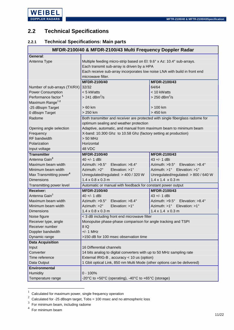
MFDR-2100/40 & MFDR-2100/43 Multi Frequency Doppler Radar
General:
Antenna Type Multiple feeding micro-strip based on El: 9.6° x Az: 10.4° sub-arrays.
Each transmit sub-array is driven by a HPA
Each receive sub-array incorporates low noise LNA with build in front end
microwave filter.
MFDR-2100/40 MFDR-2100/43
Number of sub-arrays (TX/RX) 32/32 64/64
Power Consumption < 5 kWatts < 10 kWatts
Performance factor 1 > 241 dBm
2/s > 250 dBm
2/s
Maximum Range1 2
-25 dBsqm Target
0 dBsqm Target
> 60 km
> 250 km
> 100 km
> 450 km
Radome Both transmitter and receiver are protected with single fiberglass radome for
optimum sealing and weather protection
Opening angle selection Adaptive, automatic, and manual from maximum beam to minimum beam
Frequency X-band: 10.300 Ghz to 10.58 Ghz (factory setting at production)
RF bandwidth > 50 MHz
Polarization Horizontal
Input voltage 48 VDC
Transmitter MFDR-2100/40 MFDR-2100/43
Antenna Gain3 40 +/- 1 dBi 43 +/- 1 dBi
Maximum beam width Azimuth: >9.5° Elevation: >8.4° Azimuth: >9.5° Elevation: >8.4°
Minimum beam width Azimuth: >2° Elevation: >1° Azimuth: >1° Elevation: >1°
Max Transmitting power4 Unregulated/regulated: > 400 / 320 W Unregulated/regulated: > 800 / 640 W
Dimensions 1.4 x 0.8 x 0.3 m 1.4 x 1.4 x 0.3 m
Transmitting power level Automatic or manual with feedback for constant power output
Receiver: MFDR-2100/40 MFDR-2100/43
Antenna Gain3 40 +/- 1 dBi 43 +/- 1 dBi
Maximum beam width Azimuth: >9.5° Elevation: >8.4° Azimuth: >9.5° Elevation: >8.4°
Minimum beam width Azimuth: >2° Elevation: >1° Azimuth: >1° Elevation: >1°
Dimensions 1.4 x 0.8 x 0.3 m 1.4 x 1.4 x 0.3 m
Noise figure < 3 dB including front end microwave filter
Receiver type, angle Monopulse phase-phase comparison for angle tracking and TSPI
Receiver number 8 IQ
Doppler bandwidth +/- 1 MHz
Dynamic range >150 dB for 100 msec observation time
Data Acquisition
Input 16 Differential channels
Converter 14 bits analog to digital converters with up to 50 MHz sampling rate
Time reference External IRIG-B , accuracy < 10 us (option)
Data Output 1 Gbit optical Link, 850 nm Multi Mode (other options can be delivered)
Environmental
Humidity 0 - 100%
Temperature range -20°C to +50°C (operating), -40°C to +65°C (storage)
1 Calculated for maximum power, single frequency operation
2 Calculated for -25 dBsqm target, Tobs = 100 msec and no atmospheric loss
3 For minimum beam, including radome
4 For minimum beam

MFTR-2100/40 & MFTR-2100/43Specification
12/22
OM-2124D & OM-2136D Dual Frequency Oscillators
Frequency 1 (F1) CW
Frequency 2 (F2) MF-CW or FM-CW modulation
Instrumented range > 1500 km both in MF and FM mode
F1 Duty Cycle 100%
F2 Duty Cycle >90%
F1 and F2 frequency separation From 0 to >10 MHz
MF switching time < 1msec
MF repetition frequency Form 1 Hz to at least 10 Hz
FM Sweep From 0.5 MHz to at least 50 MHz
FM repetition frequency From 1 Hz to at least 100 Hz, depend on selected sweep
CW Oscillator Phase noise OM-2124D : <-124 dBc/Hz @ 10 kHz offset
OM-2136D : <-136 dBc/Hz @ 10 kHz offset
Dimensions (HxWxD) 230 x 400 x 150 mm
Weight 13.5 kg
Environmental
Humidity 0 - 100%
Temperature range -20°C to +50°C (operating), -40°C to +65°C (storage)
AP-2100/40 Antenna Pedestal5
Elevation range -3° to >180°
Angular velocity6 >40°/sec with MFDR-2100/40 Antenna
>25°/sec with MFDR-2100/43 Antenna
Angular acceleration >40°/sec²
Encoder resolution 26 bits
Leveling resolution < 0.001°
Power Consumption 3~N 200 or 400 VAC, peak 10 kWatts
Servo 3 Fully Digital servo loops
Angular sample rate 1 - 100 ms
External Interfaces 2 ea. RS-232c/RS-422
1 Gbit optical fibre bidirectional, Multi Mode or Single Mode
1 ea. IRIG-B input
Time accuracy < 50 usec with External IRIG-B
Self test Extensive, indication to block level on operator console
Dimensions H< 2,20 m, W < 2,20 m, D < 0.75 m
Weight < 450 kg
Environmental
Humidity 0 to 100%
Temperature range -20°C to +50°C (operating), -40°C to +65°C (storage)
5 For operational configuration, including Antenna, Radome, Power Supply, Oscillator, etc
6 Dependent on actual antenna payload

MFTR-2100/40 & MFTR-2100/43Specification
13/22
RTP-2100 Real Time Processor
Real Time
Calculation Rate Velocity, range, and azimuth & elevation error angles are calculated
on-line up to 1000 times/second for multiple objects
Number of Multiple Objects 256
Tracking Simultaneously phase-phase comparison monopulse measurement on
CW and FM-CW. The antenna pointing is either taken from CW or
FM-CW - This is performed automatic or user controlled.
Range MF-CW or FM-CW with automatic or user controlled switching
Velocity CW or FM-CW with automatic or user controlled switching
Complex FFT’s 4 ea CFFT’s for CW and 4 ea CFFT’s for MF-CW or FM/CW
FFT Observation time From 256 μsec to >1 sec @ 1 MHz sample rate (256 to 1M Points)
Trajectory Motion Compensation Velocity and acceleration input for trajectory motion compensation are estimated in-real time based on measured data or pre-loaded data
Platform motion compensation Continuous stabilization of the antenna pointing relative to inertial North-East-Down frame using attitude information from external IMU. Automatic compensation of radar location relative to external cueing sources (nominal trajectories, master and slave data) using position information from external GPS receiver
Velocity Range > 8,000 m/s
Instrumented range > 1,500 km
Data Acquisition
Input 16 digital channels from Antenna through 1 Gbit optical Link
Data storage To external Real Time Data Storage - RTDS-2100
Digital Section
Central processor cPCI Intel based with, memory, Interfaces, hard-disc, etc
Operating system VxWorks
Signal processor 6 ea. Analog Devices TigerShark Array - 9 Gflops
High Speed interface 1 Gbit optical Link, 850 nm Multi Mode (other options can be delivered)
Interfaces 2 ea. RS-422, Ethernet
General
Dimensions 19" rack mountable. Height: 4U Depth : 50 cm
Weight < 20 kg
Power consumption < 200 Watt
Temperature range 0°C to +40°C (operating), -40°C to +65°C (storage)
Humidity 0 to 95% non-condensing at +40°C
RTP-2100 Real Time Processor

MFTR-2100/40 & MFTR-2100/43Specification
14/22
CA-2100/40 Continuous Azimuth
Angular velocity > 25 °/sec
Angular acc. > 25°/sec²
Servo 1 Digital servo loops
Encoder resolution >22 bits (<0.0001°)
Angular sample rate 1 - 100 ms
Power Consumption 3~N 400 VAC, < 5 kWatts
Dimensions Diameter < 1 meter , Height < 1.5 meter
Weight < 1500 kg
Environmental
Humidity 0 to 100%
Temperature range -20°C to +50°C (operating), -40°C to +65°C (storage)
MFDR-2100/43/AP-2100/40 mounted on CA-2100/40
CU-2100/40 Transmitter Cooling
Type Water based forced cooling
Cooling effect (46/49) > 20 kWatt
Cooling liquid Water with anti freeze (glycol)
Dimensions L< 2.0 meter , W < 1.5 meter , H < 1.5 meter
Weight (46/49) < 200 kg
Environmental
Humidity 0 to 100%
Temperature range -20°C to +50°C (operating), -40°C to +65°C (storage)

MFTR-2100/40 & MFTR-2100/43Specification
15/22
PS-5000 Power Supply
Mains Input 3~N 200 VAC or 3~N 400 VAC
Output 48 VDC, 5 kWatt
Dimensions L< 0.6 meter , W < 0.4 meter , H < 0.3 meter
Weight < 60 kg
Environmental
Humidity 0 to 100%
Temperature range -20°C to +50°C (operating), -40°C to +65°C (storage)
RTDS- 2100 Real Time Data Storage7
Processor Intel Dual Core: > 1.86 GHz
Memory Minimum 1 GBbyte RAM
Mass storage > 200 Gbyte high speed hard drive
Sustained storage > 32 Mbyte/sec
Operating system Windows XP or Vista
RTDS-2100 software Weibel Real-Time Storage software
High speed interface 1 Gbit Ethernet – Jumbo Frame compatible
System interface Ethernet
Data storage DVD-RW
Temperature range 0°C to +40°C (operating), -40°C to +65°C (storage)
Humidity 0 to 95% non-condensing at +40°C
Dimensions 19" rack mountable, 4U
Power consumption < 650 Watts
IC-2100 Instrumentation Controller7
Processor Intel Dual Core: > 1.86 GHz
Memory Minimum 1 GBbyte RAM
Mass storage > 80 Gbyte hard drive internal
Monitor 17" color monitor
Operating system Windows XP or Vista
IC-2100 software WinTrack Operator Real-time control, display and post processing software
System interface Ethernet
Data storage DVD-RW
Temperature range 0°C to +40°C (operating), -40°C to +65°C (storage)
Humidity 0 to 95% non-condensing at +40°C
Dimensions 19" rack mountable, 4U
Power consumption < 650 Watts
7 Typical specifications – Other configurations available

MFTR-2100/40 & MFTR-2100/43Specification
16/22
2.2.2 Technical Specifications: Options
RTD-2100 Real Time Display7
Processor Intel Dual Core: > 1.86 GHz
Memory Minimum 1 GBbyte RAM
Mass storage > 80 Gbyte hard drive internal
Monitor 17" color monitor
Operating system Windows XP or Vista
RTD-2100 software Weibel Real-Time DTI and A-Scope software
System interface Ethernet
Temperature range 0°C to +40°C (operating), -40°C to +65°C (storage)
Humidity 0 to 95% non-condensing at +40°C
Dimensions 19" rack mountable, 4U
Power consumption < 650 Watts
MCS-2100 Motion Compensation System
General Motion Compensation System used to measure platform motion in case the radar is placed on a non fixed platform such as a ship.
IMU Kearfott SEANAV IMU or similar
GPS Receiver Novatel PROPAK-V3-HP-424 GPS
Software Motion compensation software in the RTP-2100
BSC-2100 Bore Sight Camera8
Type Panasonic WV-CP484, Colour
Resolution 752*582 pixels
Zoom range 15 to 375 mm
Exposure range 1/50 to 1/10000 sec
Focal range 3 m to infinite
Horizontal & Vertical FOV 17.6° to 0.7°, 13.2° to 0.5°
Dynamic Range 54 dB (typical)
Signal to Noise Ratio 50 dB (AGC: Off, Weight: On)
Horizontal Resolution 540 lines (typical)
Minimum Illumination 0.06 lux (F1.2 , B/W)
8 Typical camera configuration. Several Bore Sight Camera configurations are available

MFTR-2100/40 & MFTR-2100/43Specification
17/22
VT-2100 Video Tracker
General
Detection Multiple and single target detection modes available
Detection Window Position: Movable to any FoV position
Number of Targets 5
Overlay Symbology overlay of Radar track data, boresight marker, status
Other Break lock and re-acquire algorithms
Programable two axis platform drive (PID) filters
Target tracking
Selectable algorithm - Centroid
- Correlation
- Edge (top, bottom, left, right)
- Multiple Target Track
- Others
Track Window Position: Automatically controlled to follow target to any FoV position
Size: Variable from 4% to 90% of the FoV with manual or adaptive modes
Video Inputs 2 Analog Inputs: Composite Video 1.0Vp-p, 625/525 Line, CCIR, PAL or RS170, NTSC, differential
Video Outputs 4 Analog: Composite video 1.0Vp-p into 75 Ohm, single ended
Control Interfaces
Serial 4 ea. RS232 and/or RS422, asynchronous, up to 115,200 baud
VT-2100 tracking airplane
MC-100 Monopulse Caliration Device
Operating Frequency X-band: 10.300 Ghz to 10.58 Ghz (factory setting at production)
Gain 20 dB
opening angle 8 x 18°
Dimensions 175 x 181 x 40 mm
Weight 2.1 kg
transporter frequency 32768 kHz (factory adjustable)
Power input 12-24 Volt DC

MFTR-2100/40 & MFTR-2100/43Specification
18/22
TR-2100 Transformer
Mains Input 3~N 170-200 VAC, 42 kVA
Output 1 3~N 380 VAC +/- 10%, 40 kVA
Output 2 1~N 220 VAC +/- 10%, 10 Amps
Humidity 0 to 100%
Housing IP55 with cooling
Dimensions H < 100, W < 80, L < 40
Weight < 450 kg
Environmental
Humidity 0 to 100%
Temperature range -20°C to +50°C (operating), -40°C to +65°C (storage)
OPS-2100 20 Operator Shelter
Type 20 feet ISO container with one door and two windows
Operator / Work spaces 3
Instrumentation Rack 42U 19" instrumentation rack for: RTP-2100, RTDS-2100, RTD-2100, IC2100, 16 port Ethernet switch, Video control, etc
Storage shelves & drawers 1 set
Climate Air condition and heating panels
Connector panel Outside for easy access
Dimensions L = 20 feet, W = 2435 mm, H = 2591 mm
Weight < 2.500 Kg
Environmental
Humidity 0 to 100%
Temperature range -20°C to +50°C (operating), -40°C to +65°C (storage)
OPS-2100 20 feet shelter

MFTR-2100/40 & MFTR-2100/43Specification
19/22
MTB-2100/40 Trailer
Type 5.500 kg trailer, 2 axis
Maximum payload 3.500 kg
Leveling Hydraulic adjustable leveling
Other Sealed storage compartments
Dimensions L < 4,1meter, W < 2,55 meter, H < 1 meter
Weight < 2.000 kg
Environmental
Humidity 0 to 100%
Temperature range -20°C to +50°C (operating), -40°C to +65°C (storage)
MFTR-2100/40 & CA-2100/40 on MTB-2100/40

MFTR-2100/40 & MFTR-2100/43Specification
20/22
2.3 Data output
The system uses FFT to extract the Time, Velocity, Range, and Azimuth & Elevation angles for multiple objects from the 8 IQ Doppler signals. This is done in real-time in the RTP or as a post process in the RTP/WinTrack. In most cases, the complete trajectory analysis can be performed directly on the on-line results and is available immediately after the complete signal has been collected.
The system stores the digitized Doppler signals and the on-line results in the RTP or RTDS in real-time enabling the system to perform measurements lasting for hours and not loose any information for off-line processing.
The system outputs are calculated based on the time, velocity, range, and angular positions results from either the on-line analysis or from the post process the results can be presented in multiple coordinate systems and include among others:
Graphical Output to Instrumentation Controller and hardcopy (Examples): ! VTI, ETI, ATI and RTI ! Velocity versus time and distance (radial, 3D, and tangential velocity) for multiple objects ! Acceleration versus time and distance (radial, 3D, and tangential acceleration) ! Distance versus time ! Vertical angle of sight versus time and horizontal angle of sight versus time ! Vertical trajectory, horizontal trajectory and offset trajectory ! Drag coefficient (CD) versus time and Mach number ! Target motion analysis (spin) ! Spin versus time and distance ! Doppler signal versus time, for each channel ! User specified graphics Numerical Output to Instrumentation Controller, file or hardcopy: ! Velocity & Range results ! Azimuth & Elevation angle results ! 3-D Trajectory, and drag results ! Calculator function ! User specified events ! Parameter settings Data storage and retrieval from mass memory The following can be stored on the Instrumentation Controller disks: ! RTP tracking results, stored in real-time ! Digitized Doppler signal including data acquisition parameters and antenna elevation & azimuth
angles ! Post processing results for further analysis ! 3-D position, angle, and velocity results ! Ballistic results from PM or MPM trajectory model ! Raw Time, Velocity, and Position data from off-line or on-line analysis ! Setup parameters for the RTP-2100 Real-Time processor and the AP-2100 pedestal ! Numerical output stored in ASCII files ! Graphical output stored in standard graphical formats

MFTR-2100/40 & MFTR-2100/43Specification
21/22
3. TRACKING MODES
The system tracks the target both in azimuth and elevation. The system can operate in 7 different modes independently in both azimuth and elevation. In all modes the actual trajectory can be computed and displayed for all objects moving in the radar beam. ! Active real time tracking on moving target. In this mode the radar follows the moving target based on real time closed loop servo using spectrum analysis and digital signal processing. If the active real-time track is lost, the system automatically estimates the trajectory based on the data up to that point. The radar will follow the estimated trajectory until valid measuring points are collected again and the system returns to the active mode. ! Preprogrammed illumination operation. The antenna moves in accordance with predetermined trajectory data, but measures the radial velocity and angles to the target in both azimuth & elevation as long as the target follows the predetermined trajectory. The predefined trajectory can be updated in real-time based on the actual measurement either automatic or manually. It is, at any time, possible to command the system into the active real time tracking mode and back to the preprogrammed mode if desired. ! Fixed head illumination operation. The antenna does not move, but measures the radial velocity and azimuth & elevation angles to the target. It is, at any time, possible to command the system into the active real time tracking mode. ! Manually tracking illumination operation. The user can, while reading the on-line results from the tracking controller, manually move the antenna, either with the cursor keys or with an optional joy-stick. It is, at any time, possible to command the system into the active real time tracking mode. ! Cued mode operation. In this mode the system receives its elevation and azimuth angles from another device, e.g, another Tracking radard working as master device. Also GPS position data or a user specified protocol can be used as master input data. It is, at any time, possible to command the system into the active real time tracking mode and back to either fixed illumination or slaved mode. ! Video Track operation. In this mode the system determines its elevation and azimuth based on the tracking error information from the optional VT-2100 Video Tracker, this mode is especially useful when acquiring free flying targets i.e. airplanes. ! Scanning mode. In this mode the system scans a predefined sector, looking for targets. This mode is useful when acquiring free flying targets e.g. airplanes or drones.

weibel.dk
Doc ID: CS-1017-006 Prepared by: FK Date: MAR-2009 Expires: APR-2010
22/22
NORTH AMERICA: 44001 Indian Fields Court Lansdowne, VA 20176-1641 USA Phone: +1-571-278-1989 Fax: +1-425-699-8211 E-mail: [email protected] GERMANY: Weibel Equipment GmbH Am Oxer 35 24955 Harrislee Germany Phone: 08001-820429 E-mail: [email protected] HEADQUARTERS: Solvang 30 3450 Allerød Denmark Phone: +45-7010-8511 Fax: +45-7010-6558 E-mail: [email protected] Web: www.weibel.dk
Notes: Contractor reserves the right to change the specifications as long as overall performance is not decreased All specifications are typical and can not be guaranteed under all conditions Not all features are included in all configurations and some features may be offered as options Not all specifications can be meet simultaneously