mg586 calibration and maintenance - · pdf filesmall crane operator ... reeling drum- 90 ft....
TRANSCRIPT

MG586 Calibration and Maintenance
MG586 Calibration and Maintenance

Set Up and Calibration of the Greer MicroGuard® 586 Computer System
“ The Best Tool The Small Crane OperatorEver Had! ”

A Little History Review
Predecessor- the MG-585 Display 1st Installed in 1999
By the fall of 2001, Terex announced its plans to install a Greer MG-586 RCI on every Boom Truck crane it manufactured in the United States. A true industry first.
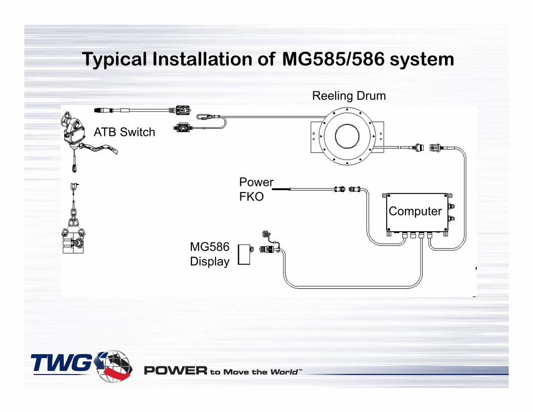
Typical Installation of MG585/586 system
Computer
Reeling Drum
ATB Switch
MG586 Display
PowerFKO

Description: MG585 Display Unit

90%Capacity
100%CapacityATB
LightSetupWindow Setup
Button
RadiusCancelButton
MomentBar
HookLoad
Boom Angle
MaxLoad
ContrastButton
SelectButton
Description: MG586 Display Unit

Internal Transducers
System Chip
CommIndicator
FKO Fuse
Computer Components
Power Supply Indicators

Power and FKO
Display Harness Reel /
ATBHarness
Connection between the Crane and the MicroGuard® System
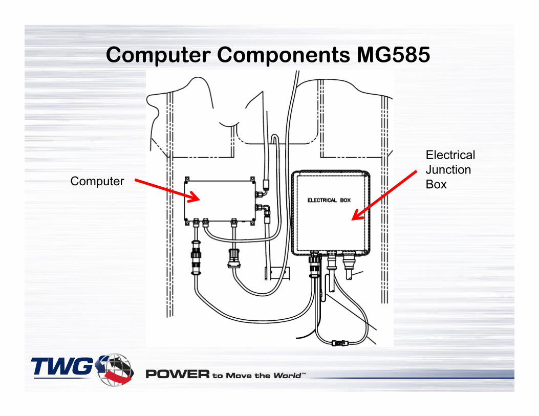
Computer
Electrical Junction Box
Computer Components MG585

Computer Components MG585
Terex Power Junction Box
Truck Shut Down Relay
Main Power Relay
System Circuit Breakers

New Computer Design for Terex MG586 Model A450655
Starting 2001
500R Computer System

Powering up the System
Circuit Breakers(Pluggable) Main Power
RelayStop Relay
Circuit BreakerPower Indicators

Reeling Drum- 90 ft. Span
Pretension is Important!!
Here are the steps:
•With cable wound on drum, rotate CW until a click is heard.
•Turn CCW 5 complete rotations for pre-loading the spring.
•Physically prevent further rotation and remove enough cable to reach the boom tip.
Tip: 3 wraps of cable = 10 Ft.
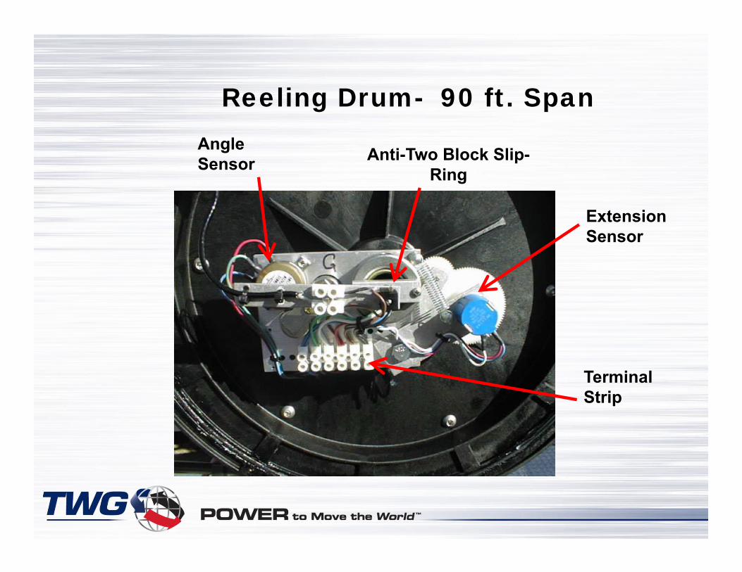
Angle Sensor Anti-Two Block Slip-
Ring
Terminal Strip
Reeling Drum- 90 ft. Span
Extension Sensor

Anti-Two Block SwitchAnti-Two Block Switch
Counter-Balanced Weight
Terminal Strip Magnetic Reed Switch
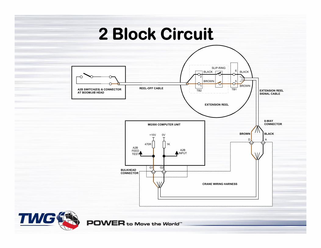
SLIP-RING
TB2
EXTENSION REEL
TB1REEL-OFF CABLEA2B SWITCH(ES) & CONNECTORAT BOOM/JIB HEAD
BLACK
2
1
BROWN 5
6 BLACK
BROWN
BLACKBROWN
CRANE WIRING HARNESS
8-WAY CONNECTOR
D A
MG500 COMPUTER UNIT
G2G1BULKHEAD CONNECTOR
470R
+10V 0V
1K
A2BINPUT
A2BFEEDTEST
EXTENSION REELSIGNAL CABLE
2 Block Circuit

MG 586 CalibrationMG 586 Calibration

Required Tools for Calibration:
Well……. First we Must Have a Few Specific Tools!!
•Digital Level- Accurate to .2º
•150 – 200 Ft. Tape Measure- in1/10’s
•Digital Volt Meter
•Before starting this procedure, the crane should be set up on level ground with outriggers properly extended and set
•It is recommended that the crane be configured with no stowed or erected jib and a single part of line.

Getting into the Calibration Mode
With the unit in the operate mode Press the Setup and Up Arrow Buttons Simultaneously and hold.
**Note: This process can take up to 8-10 seconds.
Note: To get into the Setup Mode, you must first be in the “Normal Operate” Mode on the screen.
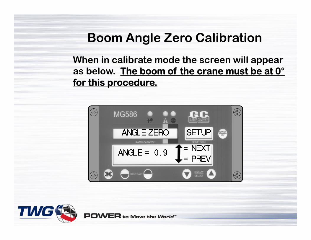
When in calibrate mode the screen will appear as below. The boom of the crane must be at 0°for this procedure.
Boom Angle Zero Calibration
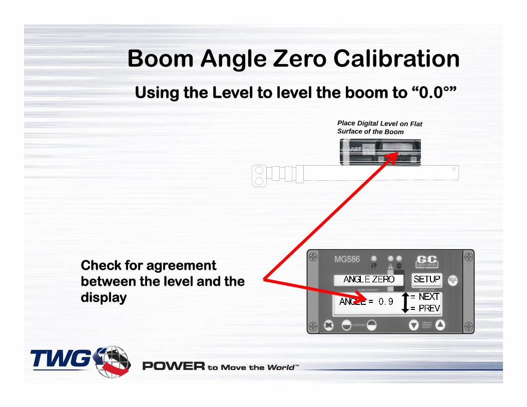
Using the Level to level the boom to “0.0°”
Check for agreement between the level and the display
Place Digital Level on Flat Surface of the Boom
Boom Angle Zero Calibration

All Angle Potentiometer plate Assy’s. go through a “pre-calibration” process at the factory. Unless tampered with, the “0”’s will probably agree.
What to do if they don’t agree:
With the Boom perfectly level:
1. Loosen angle pot attaching screws just enough to get movement.
2. Adjust pot enough to make the display read “0” degrees. Retighten the screws and recheck.
Tip: At perfectly level, voltage between the blue wire and the green wire should be approximately .475 Volts
Boom Angle Zero Calibration

Pressing the Up Arrow Button will cause the display to move on to the Extension “0” Routine. For this routine the boom must be fully retracted. The Screen will then appear as below:
Extension Pot must read “0”
Extension Zero Calibration
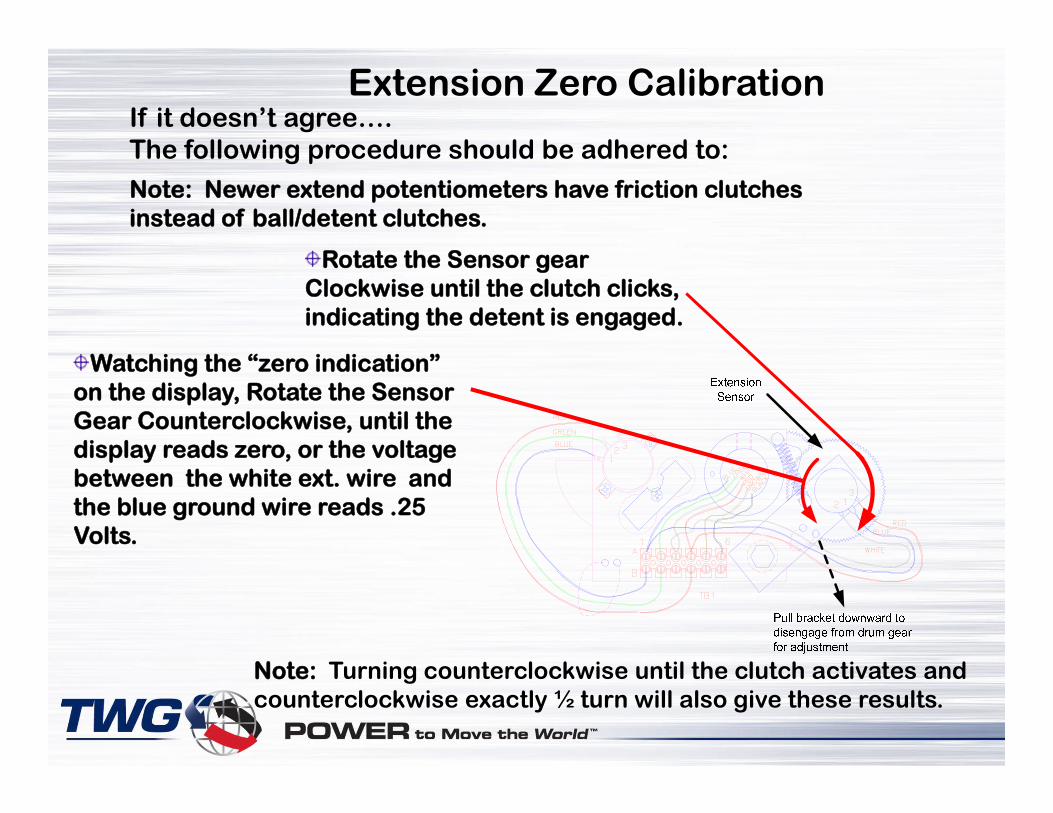
If it doesn’t agree…. The following procedure should be adhered to:
Rotate the Sensor gear Clockwise until the clutch clicks, indicating the detent is engaged.
Watching the “zero indication” on the display, Rotate the Sensor Gear Counterclockwise, until the display reads zero, or the voltage between the white ext. wire and the blue ground wire reads .25 Volts.
Note: Newer extend potentiometers have friction clutches instead of ball/detent clutches.
Note: Turning counterclockwise until the clutch activates and counterclockwise exactly ½ turn will also give these results.
Extension Zero Calibration

After releasing the spring loaded arm, the display should remain at 0.0 as shown below. If it shows a .1 or .2 difference, pressing the Setup button will cause it to read “0”. Extension Zero routine has now been completed.
Display must read zero
Extension Zero Calibration

Setting Spans for Boom Angle/Extension
Extended Length - Retracted Length = Extension Span
Span of Boom Angle
The MG586 contains a program feature that automatically sets the span of the extension and the span of the angle.
The procedure for this is simple and easy to follow:
1. Set the boom angle at exactly 60° on your digital level.
2. Fully extend the boom (at a safe angle) until you hear the cylinder physically “bottom out” with a “clunk”.
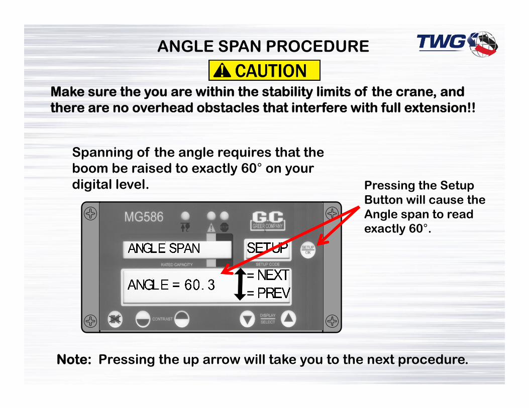
ANGLE SPAN PROCEDURE
Spanning of the angle requires that the boom be raised to exactly 60° on your digital level. Pressing the Setup
Button will cause the Angle span to read exactly 60°.
Note: Pressing the up arrow will take you to the next procedure.
Make sure the you are within the stability limits of the crane, and there are no overhead obstacles that interfere with full extension!!

Once we teach the computer where the retracted point of the boom is, we must teach it where the extended point is. This is a process call “Spanning” the extension. The MG 586 has the capability of doing this automatically. All you have to do is be in the “Length Trim screen”, and fully extend the boom, the system will do the rest.
Make sure the you are within the stability limits of the crane, and there are no overhead obstacles that interfere with full extension!!
Setting Span for Boom Extension

SETUPLENGTH TRIM
Length = 28.0 NEXTPREV
The Length Trim Screen will reflect the retracted boom length. This length number will increase as the boom is extended.
Setting Span for Boom Extension

Once the extension has reached the fully extended position, the display will let you know if you need to span (Trim) the extension length. It will display the fully extended length, as well as the banner “OK = TRIM”
Pressing the setup button, will trim the extension to the proper length and read as below:
Setting Span for Boom Extension
Pressing Arrow up will take you to the angle span procedure

Winch Rope Data/ChangeUsing the Setup Key starts this routine.
Pressing the Setup Key will select the Cable Limit for this particular crane model as prescribed by the Manufacturer
ROPE LIMIT SETUP
Limit = 9.6Standard
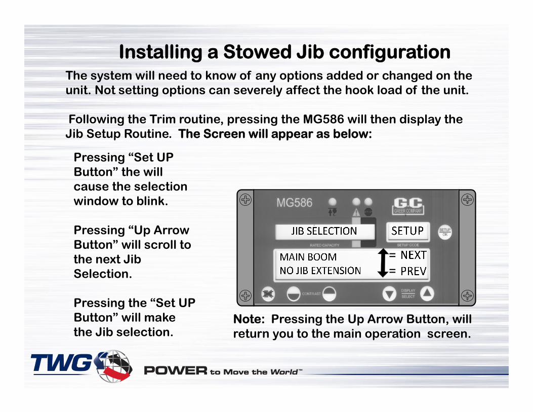
The system will need to know of any options added or changed on the unit. Not setting options can severely affect the hook load of the unit.
Following the Trim routine, pressing the MG586 will then display the Jib Setup Routine. The Screen will appear as below:
Pressing “Set UP Button” the will cause the selection window to blink.
Pressing “Up Arrow Button” will scroll to the next Jib Selection.
Pressing the “Set UP Button” will make the Jib selection.
Note: Pressing the Up Arrow Button, will return you to the main operation screen.
Installing a Stowed Jib configuration

End of PresentationEnd of Presentation
Questions???Questions???