mgsp ep27 web
TRANSCRIPT

8/10/2019 Mgsp Ep27 Web
http://slidepdf.com/reader/full/mgsp-ep27-web 1/72
8/10/2019 Mgsp Ep27 Web
http://slidepdf.com/reader/full/mgsp-ep27-web 2/72
8/10/2019 Mgsp Ep27 Web
http://slidepdf.com/reader/full/mgsp-ep27-web 3/72
8/10/2019 Mgsp Ep27 Web
http://slidepdf.com/reader/full/mgsp-ep27-web 4/72
8/10/2019 Mgsp Ep27 Web
http://slidepdf.com/reader/full/mgsp-ep27-web 5/72
8/10/2019 Mgsp Ep27 Web
http://slidepdf.com/reader/full/mgsp-ep27-web 6/72
8/10/2019 Mgsp Ep27 Web
http://slidepdf.com/reader/full/mgsp-ep27-web 7/72
8/10/2019 Mgsp Ep27 Web
http://slidepdf.com/reader/full/mgsp-ep27-web 8/72
8/10/2019 Mgsp Ep27 Web
http://slidepdf.com/reader/full/mgsp-ep27-web 9/72

8/10/2019 Mgsp Ep27 Web
http://slidepdf.com/reader/full/mgsp-ep27-web 10/72
8/10/2019 Mgsp Ep27 Web
http://slidepdf.com/reader/full/mgsp-ep27-web 11/72
8/10/2019 Mgsp Ep27 Web
http://slidepdf.com/reader/full/mgsp-ep27-web 12/72
8/10/2019 Mgsp Ep27 Web
http://slidepdf.com/reader/full/mgsp-ep27-web 13/72
8/10/2019 Mgsp Ep27 Web
http://slidepdf.com/reader/full/mgsp-ep27-web 14/72
8/10/2019 Mgsp Ep27 Web
http://slidepdf.com/reader/full/mgsp-ep27-web 15/72
V er s i on4 .7 / 4 . 9 2 / 5 .1 2
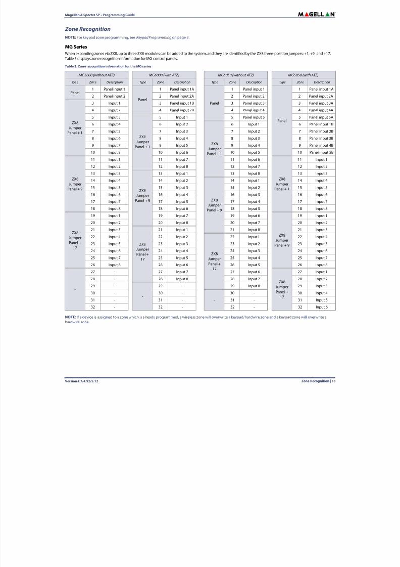
Z on eR e c o gni t i on
| 1 5
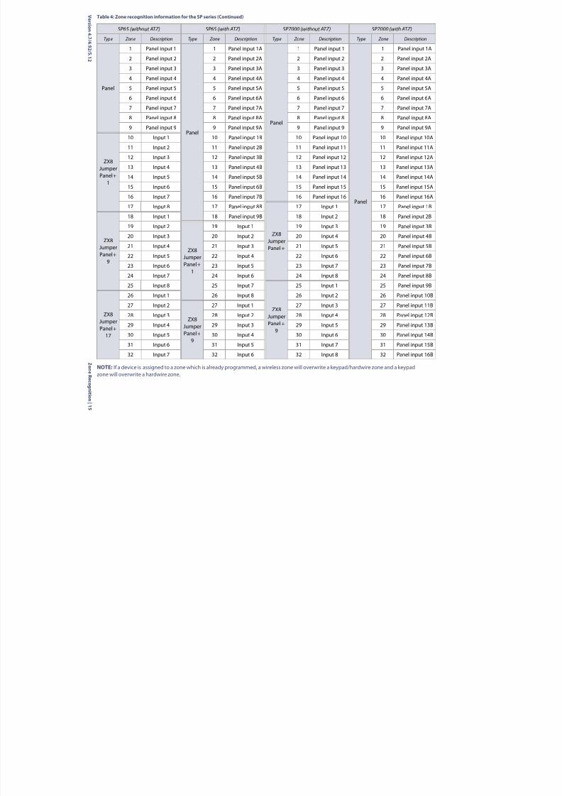
NOTE:If a device is assigned to a zone which is already programmed, a wireless zone will overwrite a keypad/hardwire zone and a keypadzone will overwrite a hardwire zone.
SP65 (without ATZ) SP65 (with ATZ) SP7000 (without ATZ) SP7000 (with ATZ)
Type Zone Description Type Zone Description Type Zone Description Type Zone Description
Panel
1 Panel input 1
Panel
1 Panel input 1A
Panel
1 Panel input 1
Panel
1 Panel input 1A
2 Panel input 2 2 Panel input 2A 2 Panel input 2 2 Panel input 2A
3 Panel input 3 3 Panel input 3A 3 Panel input 3 3 Panel input 3A
4 Panel input 4 4 Panel input 4A 4 Panel input 4 4 Panel input 4A
5 Panel input 5 5 Panel input 5A 5 Panel input 5 5 Panel input 5A
6 Panel input 6 6 Panel input 6A 6 Panel input 6 6 Panel input 6A
7 Panel input 7 7 Panel input 7A 7 Panel input 7 7 Panel input 7A8 Panel input 8 8 Panel input 8A 8 Panel input 8 8 Panel input 8A
9 Panel input 9 9 Panel input 9A 9 Panel input 9 9 Panel input 9A
ZX8JumperPanel +
1
10 Input 1 10 Panel input 1B 10 Panel input 10 10 Panel input 10A
11 Input 2 11 Panel input 2B 11 Panel input 11 11 Panel input 11A
12 Input 3 12 Panel input 3B 12 Panel input 12 12 Panel input 12A
13 Input 4 13 Panel input 4B 13 Panel input 13 13 Panel input 13A
14 Input 5 14 Panel input 5B 14 Panel input 14 14 Panel input 14A
15 Input 6 15 Panel input 6B 15 Panel input 15 15 Panel input 15A
16 Input 7 16 Panel input 7B 16 Panel input 16 16 Panel input 16A
17 Input 8 17 Panel input 8B
ZX8JumperPanel +
17 Input 1 17 Panel input 1B
ZX8JumperPanel +
9
18 Input 1 18 Panel input 9B 18 Input 2 18 Panel input 2B
19 Input 2
ZX8JumperPanel +
1
19 Input 1 19 Input 3 19 Panel input 3B
20 Input 3 20 Input 2 20 Input 4 20 Panel input 4B
21 Input 4 21 Input 3 21 Input 5 21 Panel input 5B
22 Input 5 22 Input 4 22 Input 6 22 Panel input 6B
23 Input 6 23 Input 5 23 Input 7 23 Panel input 7B
24 Input 7 24 Input 6 24 Input 8 24 Panel input 8B
25 Input 8 25 Input 7
ZX8JumperPanel +
9
25 Input 1 25 Panel input 9B
ZX8
JumperPanel +
17
26 Input 1 26 Input 8 26 Input 2 26 Panel input 10B
27 Input 2
ZX8JumperPanel +
9
27 Input 1 27 Input 3 27 Panel input 11B
28 Input 3 28 Input 2 28 Input 4 28 Panel input 12B
29 Input 4 29 Input 3 29 Input 5 29 Panel input 13B
30 Input 5 30 Input 4 30 Input 6 30 Panel input 14B
31 Input 6 31 Input 5 31 Input 7 31 Panel input 15B
32 Input 7 32 Input 6 32 Input 8 32 Panel input 16B
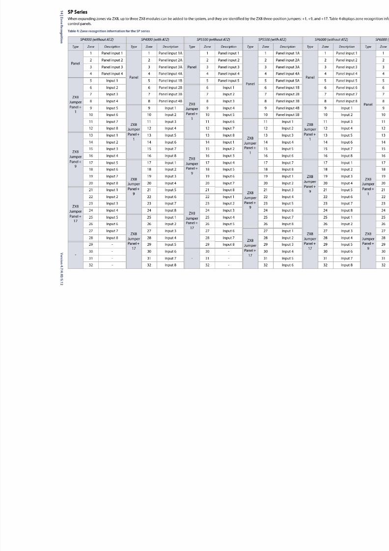
Table 4: Zone recognition information for the SP series (Continued)
8/10/2019 Mgsp Ep27 Web
http://slidepdf.com/reader/full/mgsp-ep27-web 16/72
Version 4.7/4.92/5.1216 | Zone Definitions
Magellan & Spectra SP • Programming Guide
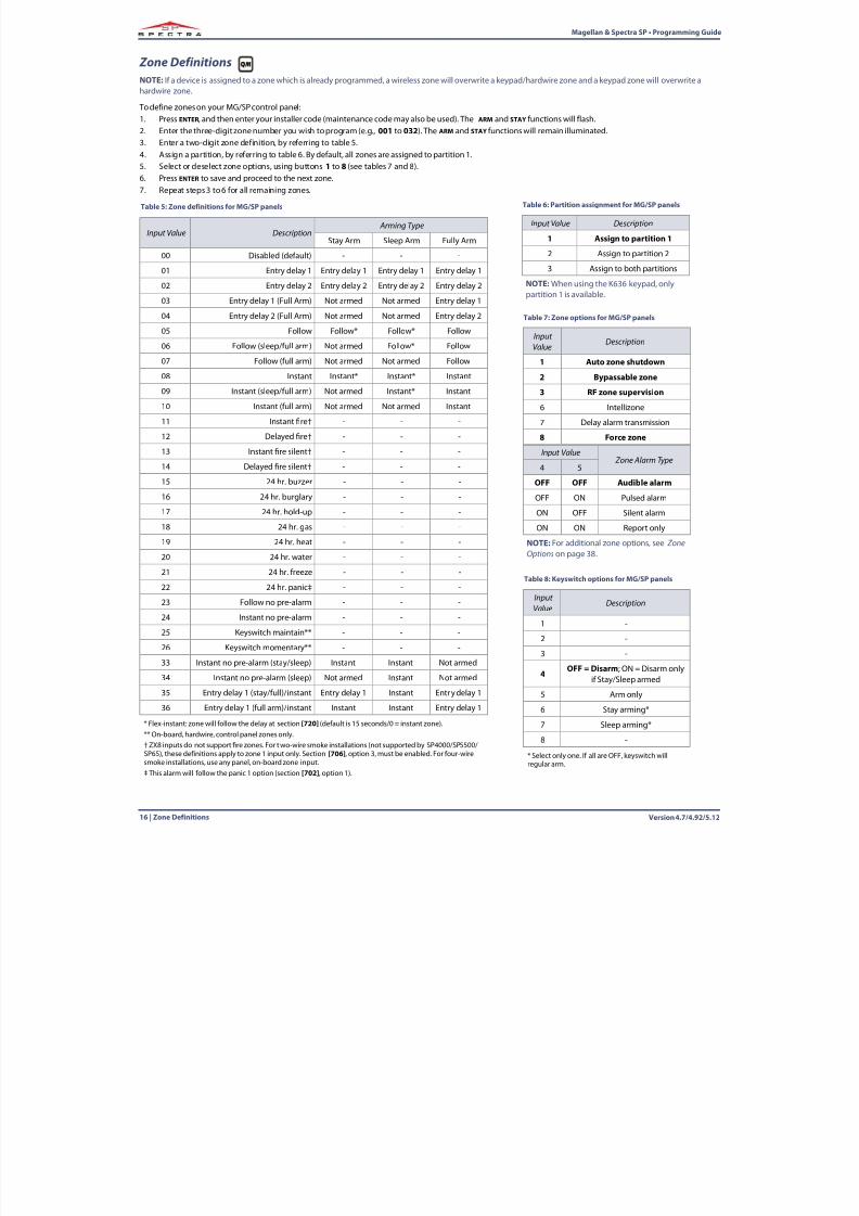
Zone DefinitionsNOTE:If a device is assigned to a zone which is already programmed, a wireless zone will overwrite a keypad/hardwire zone and a keypad zone will overwrite ahardwire zone.
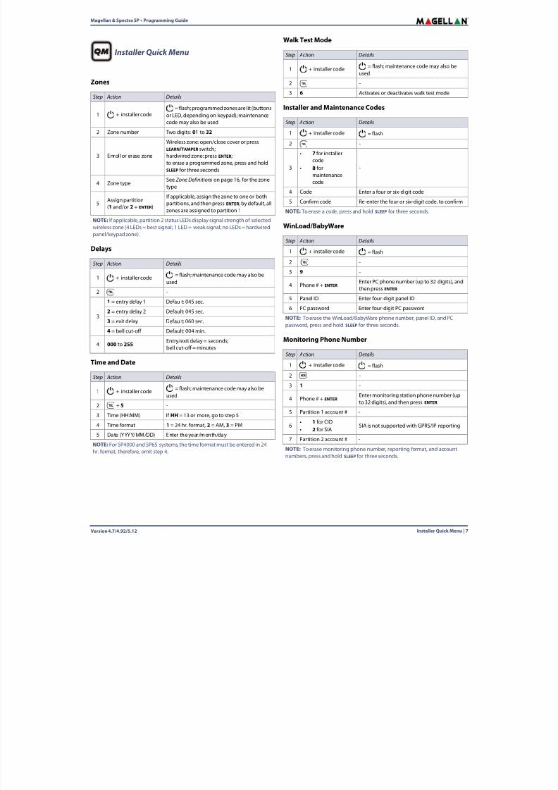
To define zones on your MG/SP control panel:1. Press ENTER, and then enter your installer code (maintenance code may also be used). The ARM and STAY functions will flash.2. Enter the three-digit zone number you wish to program (e.g., 001 to 032 ). The ARM and STAY functions will remain illuminated.3. Enter a two-digit zone definition, by referring to table 5.4. Assign a partition, by referring to table 6 . By default, all zones are assigned to partition 1.
5. Select or deselect zone options, using buttons 1 to 8 (see tables 7 and 8).6. Press ENTER to save and proceed to the next zone.7. Repeat steps 3 to 6 for all remaining zones.
Table 5: Zone definitions for MG/SP panels
Input Value Description Arming Type
Stay Arm Sleep Arm Fully Arm
00 Disabled (default) - - -
01 Entry delay 1 Entry delay 1 Entry delay 1 Entry delay 1
02 Entry delay 2 Entry delay 2 Entry delay 2 Entry delay 2
03 Entry delay 1 (Full Arm) Not armed Not armed Entry delay 1
04 Entry delay 2 (Full Arm) Not armed Not armed Entry delay 2
05 Follow Follow* Follow* Follow
06 Follow (sleep/full arm) Not armed Follow* Follow
07 Follow (full arm) Not armed Not armed Follow
08 Instant Instant* Instant* Instant
09 Instant (sleep/full arm) Not armed Instant* Instant
10 Instant (full arm) Not armed Not armed Instant
11 Instant re† - - -
12 Delayed re† - - -
13 Instant re silent† - - -
14 Delayed re silent† - - -
15 24 hr. buzzer - - -
16 24 hr. burglary - - -
17 24 hr. hold-up - - -
18 24 hr. gas - - -
19 24 hr. heat - - -
20 24 hr. water - - -
21 24 hr. freeze - - -
22 24 hr. panic‡ - - -
23 Follow no pre-alarm - - -
24 Instant no pre-alarm - - -
25 Keyswitch maintain** - - -
26 Keyswitch momentary** - - -
33 Instant no pre-alarm (stay/sleep) Instant Instant Not armed
34 Instant no pre-alarm (sleep) Not armed Instant Not armed
35 Entry delay 1 (stay/full)/instant Entry delay 1 Instant Entry delay 1
36 Entry delay 1 (full arm)/instant Instant Instant Entry delay 1
* Flex-instant: zone will follow the delay at section [720] (default is 15 seconds/0 = instant zone).** On-board, hardwire, control panel zones only.† ZX8 inputs do not support re zones. For two-wire smoke installations (not supported by SP4000/SP5500/SP65), these definitions apply to zone 1 input only. Section [706] , option 3, must be enabled. For four-wiresmoke installations, use any panel, on-board zone input.‡ This alarm will follow the panic 1 option (section [702], option 1).
Table 6: Partition assignment for MG/SP panels
Input Value Description
1 Assign to partition 1
2 Assign to partition 2
3 Assign to both partitions
NOTE:When using the K636 keypad, onlypartition 1 is available.
Table 7: Zone options for MG/SP panels
InputValue
Description
1 Auto zone shutdown
2 Bypassable zone
3 RF zone supervision
6 Intellizone
7 Delay alarm transmission
8 Force zone
Input Value Zone Alarm Type
4 5
OFF OFF Audible alarm
OFF ON Pulsed alarm
ON OFF Silent alarm
ON ON Report only
NOTE:For additional zone options, see ZoneOptions on page 38 .
Table 8: Keyswitch options for MG/SP panels
InputValue
Description
1 -
2 -
3 -4 OFF = Disarm ; ON = Disarm only
if Stay/Sleep armed
5 Arm only
6 Stay arming*
7 Sleep arming*
8 -
* Select only one. If all are OFF, keyswitch willregular arm.
8/10/2019 Mgsp Ep27 Web
http://slidepdf.com/reader/full/mgsp-ep27-web 17/72
8/10/2019 Mgsp Ep27 Web
http://slidepdf.com/reader/full/mgsp-ep27-web 18/72
Version 4.7/4.92/5.1218 | Zone Timers
Magellan & Spectra SP • Programming Guide
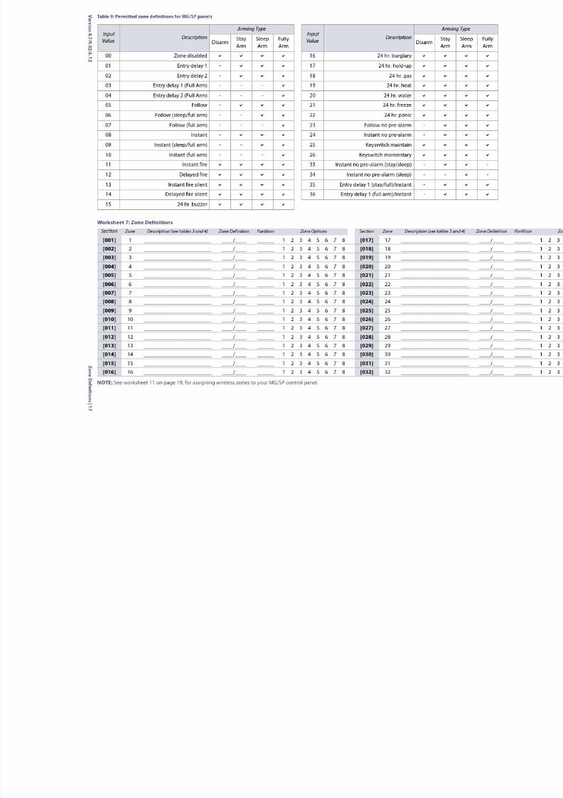
Custom Zone DefinitionsWith MG/SP control panels you can create up to four custom zone definition templates (use worksheet 8 ). Custom zone definition templates (sections [033] to[036]) will overwrite zone definitions 33 to 36 in table 5 on page 16. Modifications can be made in accordance with table 9 ( Permitted zone definitions for MG/SP panels), on page 17 .
Zone TimersUse the following section to program zone timers for your MG/SP control panel. Use worksheets 9 and 10 to record your settings.
NOTE:When both ATZ and EOL are enabled, the zone speed should not be set below 300 msec.
MG Series
SP Series
Worksheet 8: Custom Zone DefinitionsSection Description Disarm Stay Arm Sleep Arm Full Arm
[033] Zone definition template 1 _____/_____ _____/_____ _____/_____ _____/_____
[034] Zone definition template 2 _____/_____ _____/_____ _____/_____ _____/_____
[035] Zone definition template 3 _____/_____ _____/_____ _____/_____ _____/_____
[036] Zone definition template 4 _____/_____ _____/_____ _____/_____ _____/_____
Worksheet 9: Zone Timers for the MG SeriesSection Zone MG5000 MG5050 Data Description (default: 060)
[041] 1 (Z1) (Z1) ____/____/____ (000 to 255) x 10 msec. Speed of hardwire zone 1
[042] 2 (Z2) (Z2) ____/____/____ (000 to 255) x 10 msec. Speed of hardwire zone 2
[043] 3 (Z1 ATZ) (Z3) ____/____/____ (000 to 255) x 10 msec. Speed of hardwire zone 3
[044] 4 (Z2 ATZ) (Z4) ____/____/____ (000 to 255) x 10 msec. Speed of hardwire zone 4
[045] 5 (Z5) ____/____/____ (000 to 255) x 10 msec. Speed of hardwire zone 5
[046] 6 (Z1 ATZ) ____/____/____ (000 to 255) x 10 msec. Speed of hardwire zone 6
[047] 7 (Z2 ATZ) ____/____/____ (000 to 255) x 10 msec. Speed of hardwire zone 7
[048] 8 (Z3 ATZ) ____/____/____ (000 to 255) x 10 msec. Speed of hardwire zone 8
[049] 9 (Z4 ATZ) ____/____/____ (000 to 255) x 10 msec. Speed of hardwire zone 9
[050] 10 (Z5 ATZ) ____/____/____ (000 to 255) x 10 msec. Speed of hardwire zone 10
[051] 11 ____/____/____ (000 to 255) x 10 msec. Speed of hardwire zone 11
[052] 12 ____/____/____ (000 to 255) x 10 msec. Speed of hardwire zone 12
[053] 13 ____/____/____ (000 to 255) x 10 msec. Speed of hardwire zone 13
[054] 14 ____/____/____ (000 to 255) x 10 msec. Speed of hardwire zone 14
[055] 15 ____/____/____ (000 to 255) x 10 msec. Speed of hardwire zone 15
[056] 16 ____/____/____ (000 to 255) x 10 msec. Speed of hardwire zone 16
Worksheet 10: Zone Timers for the SP SeriesSection Zone SP4000 SP5500 SP6000 SP65* SP7000** Data Description (default: 060)
[041] 1 (Z1) (Z1) (Z1) (Z1) (Z1) ____/____/____ (000 to 255) x 10 msec. Speed of hardwire zone 1
[042] 2 (Z2) (Z2) (Z2) (Z2) (Z2) ____/____/____ (000 to 255) x 10 msec. Speed of hardwire zone 2
[043] 3 (Z3) (Z3) (Z3) (Z3) (Z3) ____/____/____ (000 to 255) x 10 msec. Speed of hardwire zone 3
[044] 4 (Z4) (Z4) (Z4) (Z4) (Z4) ____/____/____ (000 to 255) x 10 msec. Speed of hardwire zone 4
[045] 5 (Z1 ATZ) (Z5) (Z5) (Z5) (Z5) ____/____/____ (000 to 255) x 10 msec. Speed of hardwire zone 5
[046] 6 (Z2 ATZ) (Z1 ATZ) (Z6) (Z6) (Z6) ____/____/____ (000 to 255) x 10 msec. Speed of hardwire zone 6
[047] 7 (Z3 ATZ) (Z2 ATZ) (Z7) (Z7) (Z7) ____/____/____ (000 to 255) x 10 msec. Speed of hardwire zone 7
[048] 8 (Z4 ATZ) (Z3 ATZ) (Z8) (Z8) (Z8) ____/____/____ (000 to 255) x 10 msec. Speed of hardwire zone 8
[049] 9 (Z4 ATZ) (Z1 ATZ) (Z9) (Z9) ____/____/____ (000 to 255) x 10 msec. Speed of hardwire zone 9
[050] 10 (Z5 ATZ) (Z2 ATZ) (Z1 ATZ) (Z10) ____/____/____ (000 to 255) x 10 msec. Speed of hardwire zone 10
[051] 11 (Z3 ATZ) (Z2 ATZ) (Z11) ____/____/____ (000 to 255) x 10 msec. Speed of hardwire zone 11
[052] 12 (Z4 ATZ) (Z3 ATZ) (Z12) ____/____/____ (000 to 255) x 10 msec. Speed of hardwire zone 12
[053] 13 (Z5 ATZ) (Z4 ATZ) (Z13) ____/____/____ (000 to 255) x 10 msec. Speed of hardwire zone 13
[054] 14 (Z6 ATZ) (Z5 ATZ) (Z14) ____/____/____ (000 to 255) x 10 msec. Speed of hardwire zone 14
[055] 15 (Z7 ATZ) (Z6 ATZ) (Z15) ____/____/____ (000 to 255) x 10 msec. Speed of hardwire zone 15
[056] 16 (Z8 ATZ) (Z7 ATZ) (Z16) ____/____/____ (000 to 255) x 10 msec. Speed of hardwire zone 16* For zones 17-18 (ATZ), the zone timer is set to 600 msec.** For zones 17-32 (ATZ), the zone timer is set to 600 msec.
8/10/2019 Mgsp Ep27 Web
http://slidepdf.com/reader/full/mgsp-ep27-web 19/72
Magellan & Spectra SP • Programming Guide
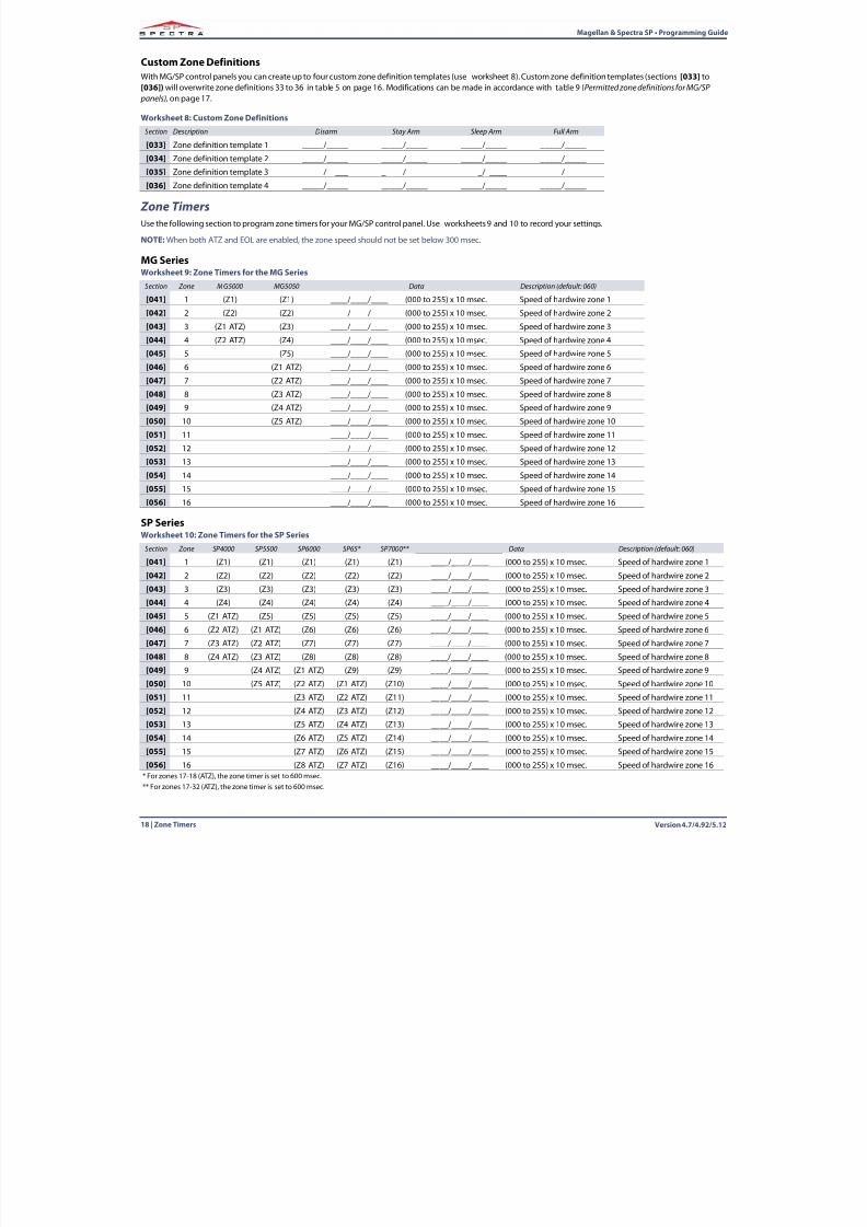
Version 4.7/4.92/5.12 Wireless Zone Assignment | 19
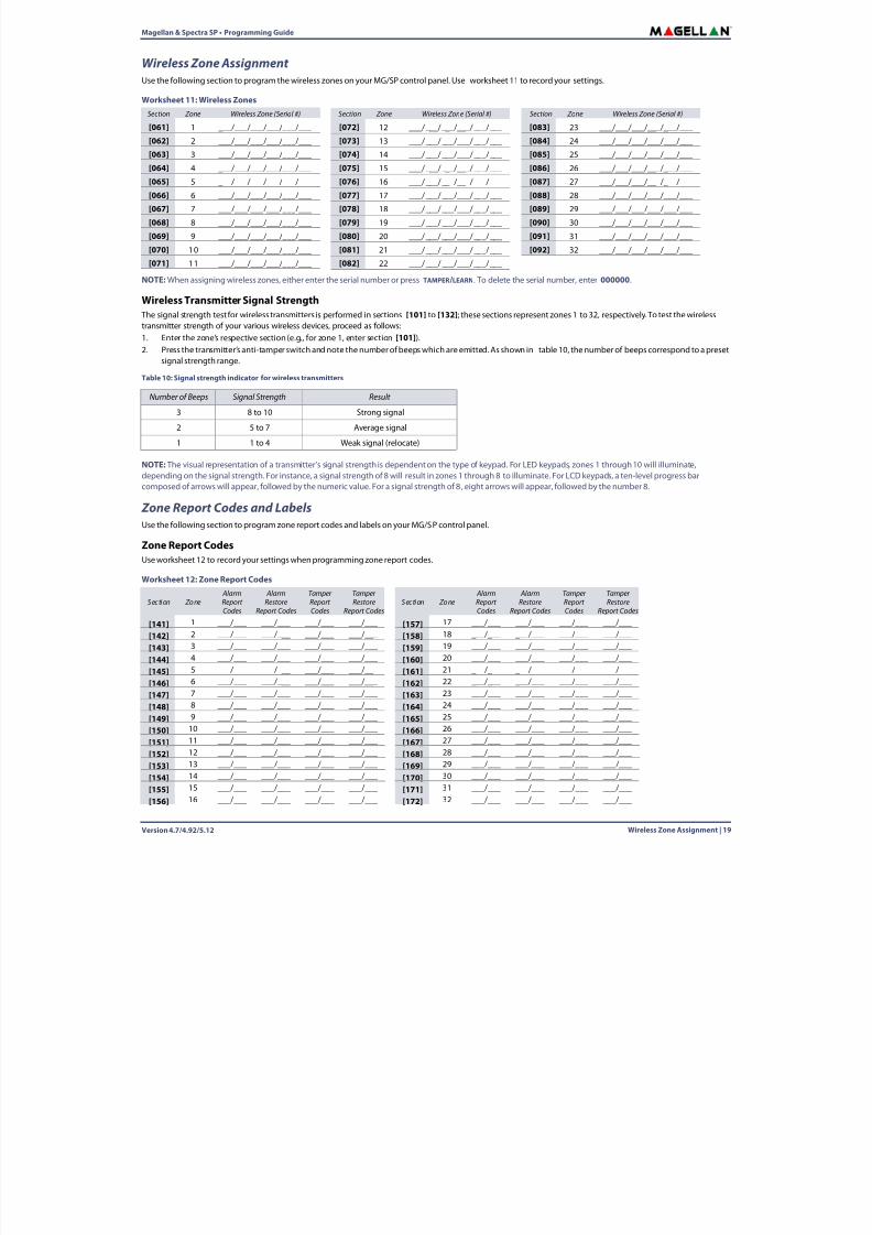
Wireless Zone Assignment Use the following section to program the wireless zones on your MG/SP control panel. Use worksheet 11 to record your settings.
NOTE:When assigning wireless zones, either enter the serial number or press TAMPER/LEARN. To delete the serial number, enter 000000 .
Wireless Transmitter Signal Strength The signal strength test for wireless transmitters is performed in sections [101] to [132] ; these sections represent zones 1 to 32, respectively. To test the wirelesstransmitter strength of your various wireless devices, proceed as follows:1. Enter the zone’s respective section (e.g., for zone 1, enter section [101] ).2. Press the transmitter’s anti-tamper switch and note the number of beeps which are emitted. As shown in table 10 , the number of beeps correspond to a preset
signal strength range.
NOTE: The visual representation of a transmitter’s signal strength is dependent on the type of keypad. For LED keypads, zones 1 through 10 will illuminate,depending on the signal strength. For instance, a signal strength of 8 will result in zones 1 through 8 to illuminate. For LCD keypads, a ten-level progress barcomposed of arrows will appear, followed by the numeric value. For a signal strength of 8 , eight arrows will appear, followed by the number 8.
Zone Report Codes and LabelsUse the following section to program zone report codes and labels on your MG/SP control panel.
Zone Report CodesUse worksheet 12 to record your settings when programming zone report codes.
Worksheet 11: Wireless ZonesSection Zone Wireless Zone (Serial #) Section Zone Wireless Zone (Serial #) Section Zone Wireless Zone (Serial #)
[061] 1 ___/___/___/___/___/___ [072] 12 ___/___/___/___/___/___ [083] 23 ___/___/___/___/___/___
[062] 2 ___/___/___/___/___/___ [073] 13 ___/___/___/___/___/___ [084] 24 ___/___/___/___/___/___
[063] 3 ___/___/___/___/___/___ [074] 14 ___/___/___/___/___/___ [085] 25 ___/___/___/___/___/___
[064] 4 ___/___/___/___/___/___ [075] 15 ___/___/___/___/___/___ [086] 26 ___/___/___/___/___/___[065] 5 ___/___/___/___/___/___ [076] 16 ___/___/___/___/___/___ [087] 27 ___/___/___/___/___/___
[066] 6 ___/___/___/___/___/___ [077] 17 ___/___/___/___/___/___ [088] 28 ___/___/___/___/___/___
[067] 7 ___/___/___/___/___/___ [078] 18 ___/___/___/___/___/___ [089] 29 ___/___/___/___/___/___
[068] 8 ___/___/___/___/___/___ [079] 19 ___/___/___/___/___/___ [090] 30 ___/___/___/___/___/___
[069] 9 ___/___/___/___/___/___ [080] 20 ___/___/___/___/___/___ [091] 31 ___/___/___/___/___/___
[070] 10 ___/___/___/___/___/___ [081] 21 ___/___/___/___/___/___ [092] 32 ___/___/___/___/___/___
[071] 11 ___/___/___/___/___/___ [082] 22 ___/___/___/___/___/___
Table 10: Signal strength indicator for wireless transmitters
Number of Beeps Signal Strength Result
3 8 to 10 Strong signal
2 5 to 7 Average signal
1 1 to 4 Weak signal (relocate)
Worksheet 12: Zone Report Codes
Section Zone AlarmReportCodes
AlarmRestore
Report Codes
TamperReportCodes
TamperRestore
Report CodesSection Zone
AlarmReportCodes
AlarmRestore
Report Codes
TamperReportCodes
TamperRestore
Report Codes
[141] 1 ___/___ ___/___ ___/___ ___/___ [157] 17 ___/___ ___/___ ___/___ ___/___
[142] 2 ___/___ ___/___ ___/___ ___/___ [158] 18 ___/___ ___/___ ___/___ ___/___
[143] 3 ___/___ ___/___ ___/___ ___/___ [159] 19 ___/___ ___/___ ___/___ ___/___
[144] 4 ___/___ ___/___ ___/___ ___/___ [160] 20 ___/___ ___/___ ___/___ ___/___
[145] 5 ___/___ ___/___ ___/___ ___/___ [161] 21 ___/___ ___/___ ___/___ ___/___[146] 6 ___/___ ___/___ ___/___ ___/___ [162] 22 ___/___ ___/___ ___/___ ___/___
[147] 7 ___/___ ___/___ ___/___ ___/___ [163] 23 ___/___ ___/___ ___/___ ___/___
[148] 8 ___/___ ___/___ ___/___ ___/___ [164] 24 ___/___ ___/___ ___/___ ___/___
[149] 9 ___/___ ___/___ ___/___ ___/___ [165] 25 ___/___ ___/___ ___/___ ___/___
[150] 10 ___/___ ___/___ ___/___ ___/___ [166] 26 ___/___ ___/___ ___/___ ___/___
[151] 11 ___/___ ___/___ ___/___ ___/___ [167] 27 ___/___ ___/___ ___/___ ___/___
[152] 12 ___/___ ___/___ ___/___ ___/___ [168] 28 ___/___ ___/___ ___/___ ___/___
[153] 13 ___/___ ___/___ ___/___ ___/___ [169] 29 ___/___ ___/___ ___/___ ___/___
[154] 14 ___/___ ___/___ ___/___ ___/___ [170] 30 ___/___ ___/___ ___/___ ___/___
[155] 15 ___/___ ___/___ ___/___ ___/___ [171] 31 ___/___ ___/___ ___/___ ___/___
[156] 16 ___/___ ___/___ ___/___ ___/___ [172] 32 ___/___ ___/___ ___/___ ___/___
8/10/2019 Mgsp Ep27 Web
http://slidepdf.com/reader/full/mgsp-ep27-web 20/72
Version 4.7/4.92/5.1220 | Programmable Output Programming
Magellan & Spectra SP • Programming Guide
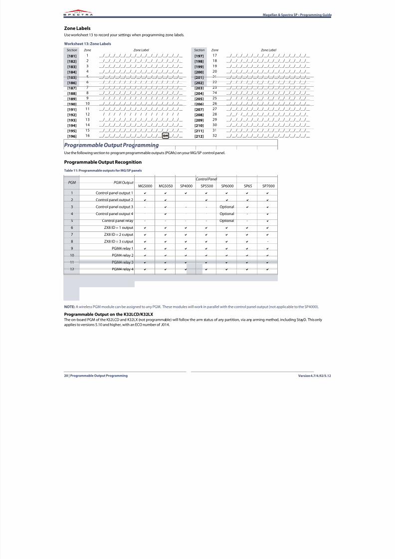
Zone LabelsUse worksheet 13 to record your settings when programming zone labels.
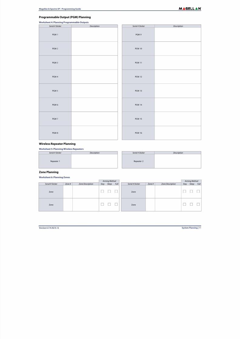
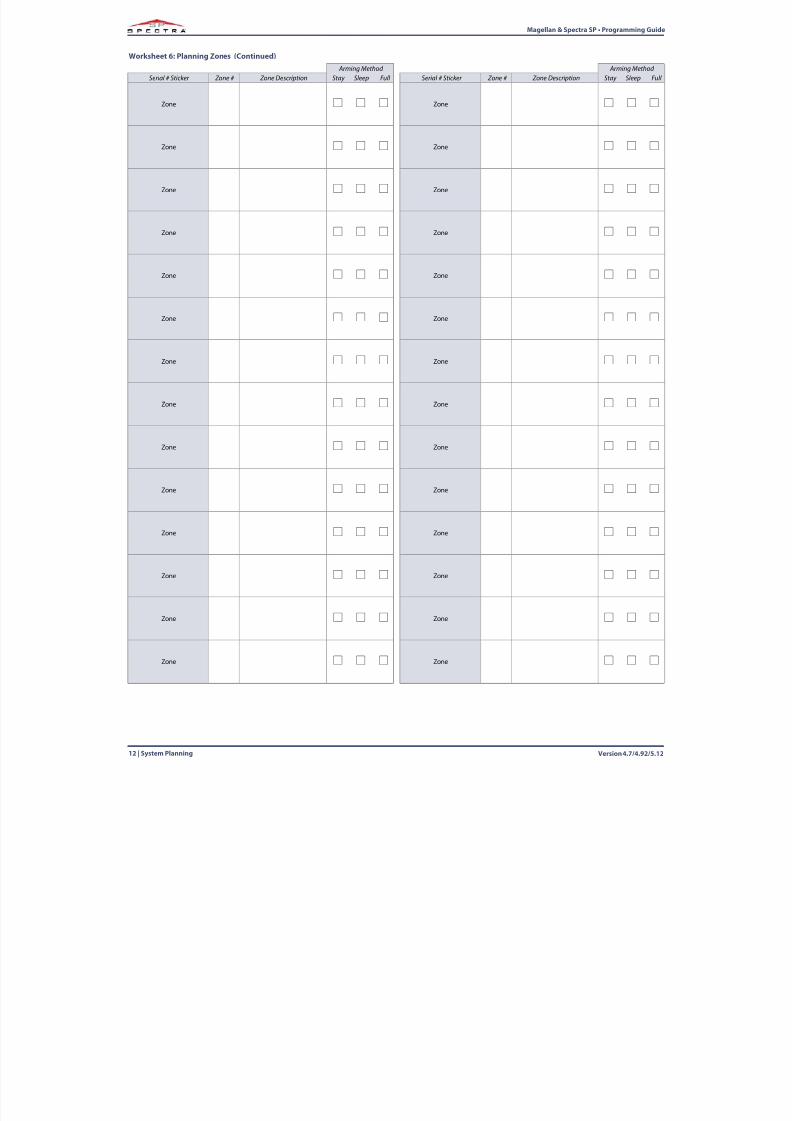
Programmable Output ProgrammingUse the following section to program programmable outputs (PGMs) on your MG/SP control panel.
Programmable Output Recognition
NOTE:A wireless PGM module can be assigned to any PGM. These modules will work in parallel with the control panel output (not applicable to the SP4000).
Programmable Output on the K32LCD/K32LX The on-board PGM of the K32LCD and K32LX (not programmable) will follow the arm status of any partition, via any arming method, including StayD. This onlyapplies to versions 5.10 and higher, with an ECO number of J014.
Worksheet 13: Zone LabelsSection Zone Zone Label Section Zone Zone Label
[181] 1 __/__/__/__/__/__/__/__/__/__/__/__/__/__/__/__ [197] 17 __/__/__/__/__/__/__/__/__/__/__/__/__/__/__/__
[182] 2 __/__/__/__/__/__/__/__/__/__/__/__/__/__/__/__ [198] 18 __/__/__/__/__/__/__/__/__/__/__/__/__/__/__/__
[183] 3 __/__/__/__/__/__/__/__/__/__/__/__/__/__/__/__ [199] 19 __/__/__/__/__/__/__/__/__/__/__/__/__/__/__/__
[184] 4 __/__/__/__/__/__/__/__/__/__/__/__/__/__/__/__ [200] 20 __/__/__/__/__/__/__/__/__/__/__/__/__/__/__/__
[185] 5 __/__/__/__/__/__/__/__/__/__/__/__/__/__/__/__ [201] 21 __/__/__/__/__/__/__/__/__/__/__/__/__/__/__/__[186] 6 __/__/__/__/__/__/__/__/__/__/__/__/__/__/__/__ [202] 22 __/__/__/__/__/__/__/__/__/__/__/__/__/__/__/__
[187] 7 __/__/__/__/__/__/__/__/__/__/__/__/__/__/__/__ [203] 23 __/__/__/__/__/__/__/__/__/__/__/__/__/__/__/__
[188] 8 __/__/__/__/__/__/__/__/__/__/__/__/__/__/__/__ [204] 24 __/__/__/__/__/__/__/__/__/__/__/__/__/__/__/__
[189] 9 __/__/__/__/__/__/__/__/__/__/__/__/__/__/__/__ [205] 25 __/__/__/__/__/__/__/__/__/__/__/__/__/__/__/__
[190] 10 __/__/__/__/__/__/__/__/__/__/__/__/__/__/__/__ [206] 26 __/__/__/__/__/__/__/__/__/__/__/__/__/__/__/__
[191] 11 __/__/__/__/__/__/__/__/__/__/__/__/__/__/__/__ [207] 27 __/__/__/__/__/__/__/__/__/__/__/__/__/__/__/__
[192] 12 __/__/__/__/__/__/__/__/__/__/__/__/__/__/__/__ [208] 28 __/__/__/__/__/__/__/__/__/__/__/__/__/__/__/__
[193] 13 __/__/__/__/__/__/__/__/__/__/__/__/__/__/__/__ [209] 29 __/__/__/__/__/__/__/__/__/__/__/__/__/__/__/__
[194] 14 __/__/__/__/__/__/__/__/__/__/__/__/__/__/__/__ [210] 30 __/__/__/__/__/__/__/__/__/__/__/__/__/__/__/__
[195] 15 __/__/__/__/__/__/__/__/__/__/__/__/__/__/__/__ [211] 31 __/__/__/__/__/__/__/__/__/__/__/__/__/__/__/__
[196] 16 __/__/__/__/__/__/__/__/__/__/__/__/__/__/__/__ [212] 32 __/__/__/__/__/__/__/__/__/__/__/__/__/__/__/__
Table 11: Programmable outputs for MG/SP panels
PGM PGM Output Control Panel
MG5000 MG5050 SP4000 SP5500 SP6000 SP65 SP7000
1 Control panel output 1
2 Control panel output 2 -
3 Control panel output 3 - - - Optional
4 Control panel output 4 - - - Optional -
5 Control panel relay - - - - Optional -
6 ZX8 ID = 1 output
7 ZX8 ID = 2 output
8 ZX8 ID = 3 output -
9 PGM4 relay 1
10 PGM4 relay 2
11 PGM4 relay 3
12 PGM4 relay 4
13 RTX3/RX1 output 1 - -
14 RTX3/RX1 output 2 - -
15 RTX3 output 3 (relay) - -
16 RTX3 output 4 (relay) Optional Optional Optional Optional Optional Optional Optional
8/10/2019 Mgsp Ep27 Web
http://slidepdf.com/reader/full/mgsp-ep27-web 21/72
Magellan & Spectra SP • Programming Guide
Version 4.7/4.92/5.12 Programmable Output Programming | 21
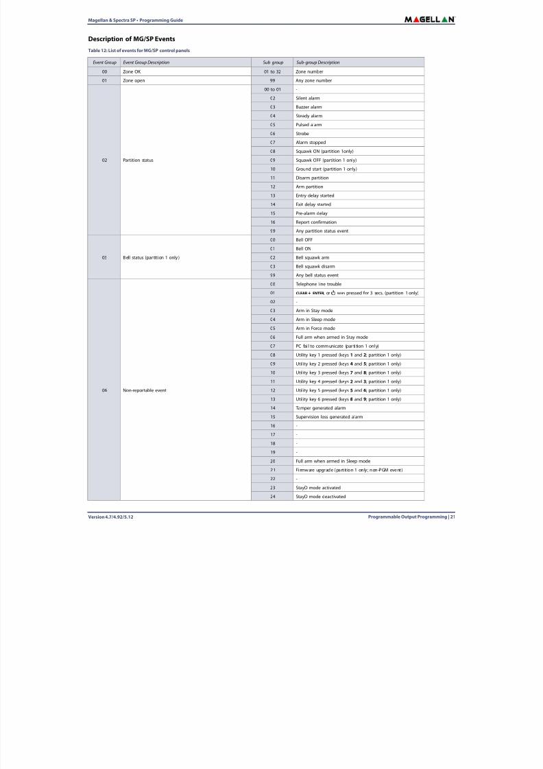
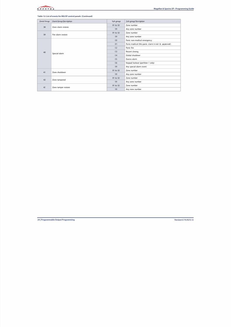
Description of MG/SP EventsTable 12: List of events for MG/SP control panels
Event Group Event Group Description Sub-group Sub-group Description
00 Zone OK 01 to 32 Zone number
01 Zone open 99 Any zone number
02 Partition status
00 to 01 -
02 Silent alarm
03 Buzzer alarm
04 Steady alarm
05 Pulsed alarm
06 Strobe
07 Alarm stopped
08 Squawk ON (partition 1only)
09 Squawk OFF (partition 1 only)
10 Ground start (partition 1 only)
11 Disarm partition
12 Arm partition
13 Entry delay started
14 Exit delay started
15 Pre-alarm delay
16 Report confirmation
99 Any partition status event
03 Bell status (par titi on 1 only )
00 Bell OFF
01 Bell ON
02 Bell squawk arm
03 Bell squawk disarm
99 Any bell status event
06 Non-reportable event
00 Telephone line trouble
01 CLEAR + ENTER, or was pressed for 3 secs. (partition 1 only)
02 -
03 Arm in Stay mode04 Arm in Sleep mode
05 Arm in Force mode
06 Full arm when armed in Stay mode
07 PC fai l to communicate (par ti tion 1 only)
08 Utility key 1 pressed (keys 1 and 2; partition 1 only)
09 Utility key 2 pressed (keys 4 and 5; partition 1 only)
10 Utility key 3 pressed (keys 7 and 8; partition 1 only)
11 Utility key 4 pressed (keys 2 and 3; partition 1 only)
12 Utility key 5 pressed (keys 5 and 6; partition 1 only)
13 Utility key 6 pressed (keys 8 and 9; partition 1 only)
14 Tamper generated alarm
15 Supervision loss generated alarm
16 -
17 -
18 -
19 -
20 Full arm when armed in Sleep mode
21 Firmware upgrade (part it ion 1 only; non-PGM event)
22 -
23 StayD mode activated
24 StayD mode deactivated

8/10/2019 Mgsp Ep27 Web
http://slidepdf.com/reader/full/mgsp-ep27-web 22/72
Version 4.7/4.92/5.1222 | Programmable Output Programming
Magellan & Spectra SP • Programming Guide
06(Cont.)
Non-reportable event(Cont.)
25 IP registration status change
26 GPRS registration status change
27 Armed with trouble(s)
28 Supervision alert
29 Supervision alert restore
30 Armed with remote with low battery99 Any non-reportable event
08 Button pressed on remote (see Default Data B, in worksheet 26on page 35 )
01 to 32 Remote control number
99 Any remote control number
09 Button pressed on remote (see Default Data C , in worksheet 26on page 35 )
01 to 32 Remote control number
99 Any remote control number
10 Button pressed on remote (see Default Data D, in worksheet 26on page 35 )
01 to 32 Remote control number
99 Any remote control number
11 Button pressed on remote (see Default Data E , in worksheet 26on page 35 )
01 to 32 Remote control number
99 Any remote control number
12 Cold start wireless zone01 to 32 Zone number
99 Any zone number
13 Cold start wireless module (partition 1 only)
01 to 16 Output number
17 to 18 Wireless repeater
19 to 26 Wireless keypad
27 to 30 Wireless siren
99 Any output number
14 Bypass programming01 to 32 User number
99 Any user number
15 User code activated output (partition 1 only)01 to 32 User number
99 Any user number
16 Wireless smoke maintenance s ignal01 to 32 Zone number
99 Any zone number
17 Delay zone al arm transmission01 to 32 Zone number
99 Any zone number
18 Zone signal strength weak 1 (partition 1 only)01 to 32 Zone number
99 Any zone number
19 Zone signal strength weak 2 (partition 1 only)01 to 32 Zone number
99 Any zone number
20 Zone signal strength weak 3 (partition 1 only)01 to 32 Zone number
99 Any zone number
21 Zone signal strength weak 4 (partition 1 only)01 to 32 Zone number
99 Any zone number
22 Button pressed on remote (see option 5, in table22 on page 34 )01 to 32 Remote control number
99 Any remote control number
23 Button pressed on remote (see option 6, in table22 on page 34 )01 to 32 Remote control number
99 Any remote control number
24 Fire delay started01 to 32 Zone number
99 Any zone number
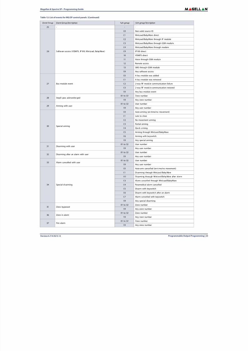
Table 12: List of events for MG/SP control panels (Continued)
Event Group Event Group Description Sub-group Sub-group Description
8/10/2019 Mgsp Ep27 Web
http://slidepdf.com/reader/full/mgsp-ep27-web 23/72
Magellan & Spectra SP • Programming Guide
Version 4.7/4.92/5.12 Programmable Output Programming | 23
25 - - -
26 Software access (VDMP3, IP100, WinLoad, BabyWare)
00 Non-valid source ID
01 WinLoad/BabyWare direct
02 WinLoad/BabyWare through IP module
03 WinLoad/BabyWare through GSM module
04 WinLoad/BabyWare through modem09 IP100 direct
10 VDMP3 direct
11 Voice through GSM module
12 Remote access
13 SMS through GSM module
99 Any software access
27 Bus module event
00 A bus module was added
01 A bus module was removed
02 2-way RF module communication failure
03 2-way RF module communication restored
99 Any bus module event
28 StayD pass acknowledged01 to 32 Zone number
99 Any zone number
29 Arming with user01 to 32 User number
99 Any user number
30 Special arming
00 Auto-arming (on-time/no movement)
01 Late to close
02 No movement arming
03 Partial arming
04 Quick arming
05 Arming through WinLoad/BabyWare
06 Arming with keyswitch
99 Any special arming
31 Disarming with user01 to 32 User number
99 Any user number
32 Disarming af ter an al arm with user01 to 32 User number
99 Any user number
33 Alarm cancelled with user01 to 32 User number
99 Any user number
34 Special disarming
00 Auto-arm cance ll ed (on-time/no movement)
01 Disarming through WinLoad/BabyWare
02 Disarming through WinLoad/BabyWare af ter alarm
03 Alarm cancelled through WinLoad/BabyWare
04 Paramedical alarm cancelled
05 Disarm with keyswitch
06 Disarm with keyswitch after an alarm
07 Alarm cancelled with keyswitch
99 Any special disarming
35 Zone bypassed01 to 32 Zone number
99 Any zone number
36 Zone in alarm01 to 32 Zone number
99 Any zone number
37 Fire alarm01 to 32 Zone number
99 Any zone number
Table 12: List of events for MG/SP control panels (Continued)
Event Group Event Group Description Sub-group Sub-group Description
8/10/2019 Mgsp Ep27 Web
http://slidepdf.com/reader/full/mgsp-ep27-web 24/72
Version 4.7/4.92/5.1224 | Programmable Output Programming
Magellan & Spectra SP • Programming Guide
38 Zone alarm restore01 to 32 Zone number
99 Any zone number
39 Fire alarm restore01 to 32 Zone number
99 Any zone number
40 Special alarm
00 Panic non-medical emergency
01 Panic medical (this panic alarm in not UL approved)02 Panic fire
03 Recent closing
04 Global shutdown
05 Duress alarm
06 Keypad lockout (partition 1 only)
99 Any special alarm event
41 Zone shutdown01 to 32 Zone number
99 Any zone number
42 Zone tampered01 to 32 Zone number
99 Any zone number
43 Zone tamper restore
01 to 32 Zone number
99 Any zone number
Table 12: List of events for MG/SP control panels (Continued)
Event Group Event Group Description Sub-group Sub-group Description
8/10/2019 Mgsp Ep27 Web
http://slidepdf.com/reader/full/mgsp-ep27-web 25/72
Magellan & Spectra SP • Programming Guide
Version 4.7/4.92/5.12 Programmable Output Programming | 25
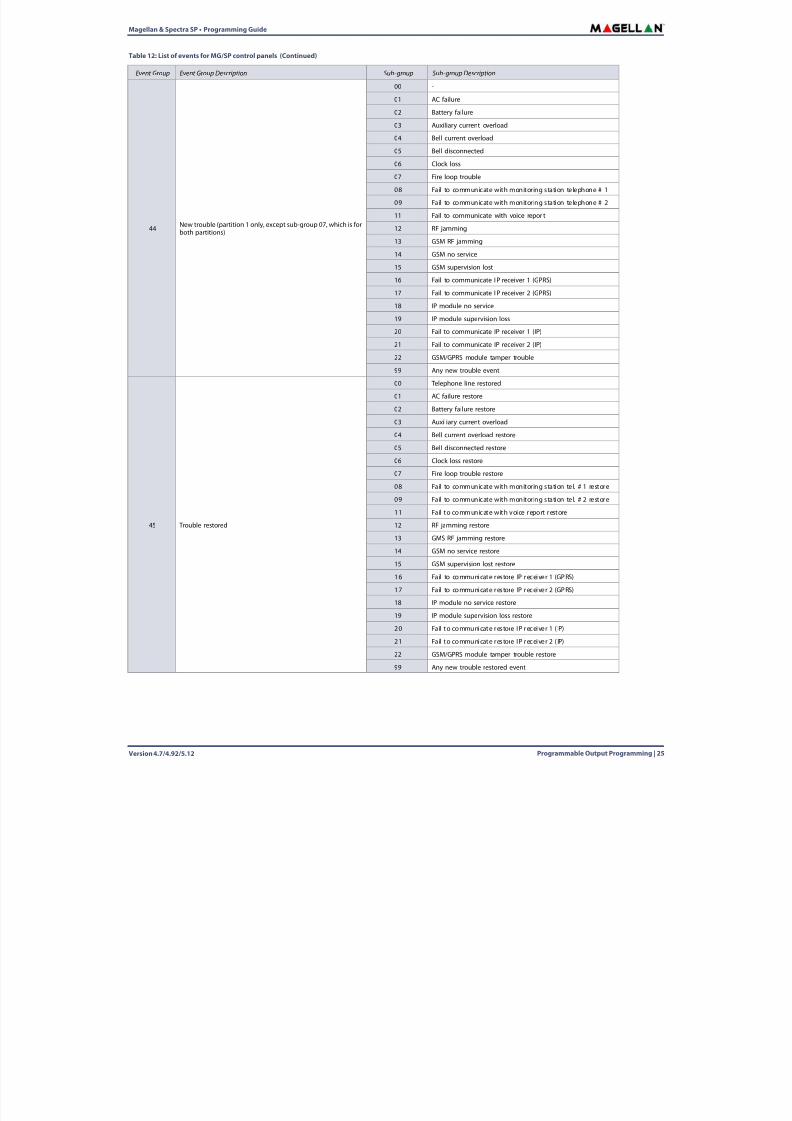
44 New trouble (partition 1 only, except sub-group 07, which is forboth partitions)
00 -
01 AC failure
02 Battery failure
03 Auxiliary current overload
04 Bell current overload
05 Bell disconnected06 Clock loss
07 Fire loop trouble
08 Fail to communicate with monitoring station telephone # 1
09 Fail to communicate with monitoring station telephone # 2
11 Fail to communicate with voice repor t
12 RF jamming
13 GSM RF jamming
14 GSM no service
15 GSM supervision lost
16 Fail to communicate IP receiver 1 (GPRS)
17 Fail to communicate IP receiver 2 (GPRS)
18 IP module no service
19 IP module supervision loss
20 Fail to communicate IP receiver 1 (IP)
21 Fail to communicate IP receiver 2 (IP)
22 GSM/GPRS module tamper trouble
99 Any new trouble event
45 Trouble restored
00 Telephone line restored
01 AC failure restore
02 Battery failure restore
03 Auxiliary current overload
04 Bell current overload restore
05 Bell disconnected restore
06 Clock loss restore
07 Fire loop trouble restore
08 Fail to communicate with monitoring station tel. # 1 restore
09 Fail to communicate with monitoring station tel. # 2 restore
11 Fail to communicate with voice report restore
12 RF jamming restore
13 GMS RF jamming restore
14 GSM no service restore
15 GSM supervision lost restore
16 Fail to communicate res tore IP receiver 1 (GPRS)
17 Fail to communicate res tore IP receiver 2 (GPRS)
18 IP module no service restore
19 IP module supervision loss restore
20 Fail to communicate res tore IP receiver 1 ( IP)
21 Fail to communicate res tore IP receiver 2 ( IP)
22 GSM/GPRS module tamper trouble restore
99 Any new trouble restored event
Table 12: List of events for MG/SP control panels (Continued)
Event Group Event Group Description Sub-group Sub-group Description
8/10/2019 Mgsp Ep27 Web
http://slidepdf.com/reader/full/mgsp-ep27-web 26/72
Version 4.7/4.92/5.1226 | Programmable Output Programming
Magellan & Spectra SP • Programming Guide
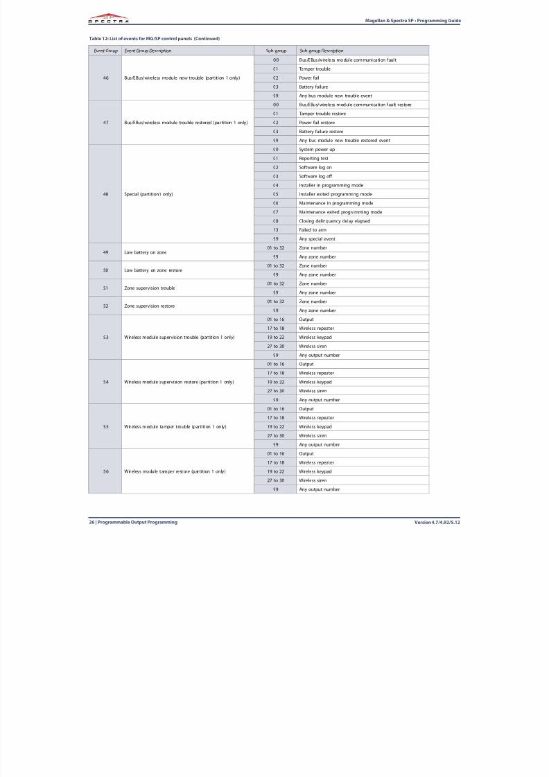
46 Bus/EBus/wireless module new trouble (partition 1 only)
00 Bus/EBus/wireless module communication faul t
01 Tamper trouble
02 Power fail
03 Battery failure
99 Any bus module new trouble event
47 Bus/EBus/wireless module trouble restored (partition 1 only)
00 Bus/EBus/wireless module communication fault restore01 Tamper trouble restore
02 Power fail restore
03 Battery failure restore
99 Any bus module new trouble restored event
48 Special (partition1 only)
00 System power up
01 Reporting test
02 Software log on
03 Software log off
04 Installer in programming mode
05 Installer exited programming mode
06 Maintenance in programming mode
07 Maintenance exited programming mode
08 Closing delinquency delay elapsed
13 Failed to arm
99 Any special event
49 Low battery on zone01 to 32 Zone number
99 Any zone number
50 Low battery on zone restore01 to 32 Zone number
99 Any zone number
51 Zone supervision trouble01 to 32 Zone number
99 Any zone number
52 Zone supervision restore01 to 32 Zone number
99 Any zone number
53 Wireless module supervision trouble (partition 1 only)
01 to 16 Output
17 to 18 Wireless repeater
19 to 22 Wireless keypad
27 to 30 Wireless siren
99 Any output number
54 Wireless module supervision restore (partition 1 only)
01 to 16 Output
17 to 18 Wireless repeater
19 to 22 Wireless keypad
27 to 30 Wireless siren
99 Any output number
55 Wireless module tamper trouble (partition 1 only)
01 to 16 Output
17 to 18 Wireless repeater
19 to 22 Wireless keypad
27 to 30 Wireless siren
99 Any output number
56 Wireless module tamper restore (partition 1 only)
01 to 16 Output
17 to 18 Wireless repeater
19 to 22 Wireless keypad
27 to 30 Wireless siren
99 Any output number
Table 12: List of events for MG/SP control panels (Continued)
Event Group Event Group Description Sub-group Sub-group Description
8/10/2019 Mgsp Ep27 Web
http://slidepdf.com/reader/full/mgsp-ep27-web 27/72
Magellan & Spectra SP • Programming Guide
Version 4.7/4.92/5.12 Programmable Output Programming | 27
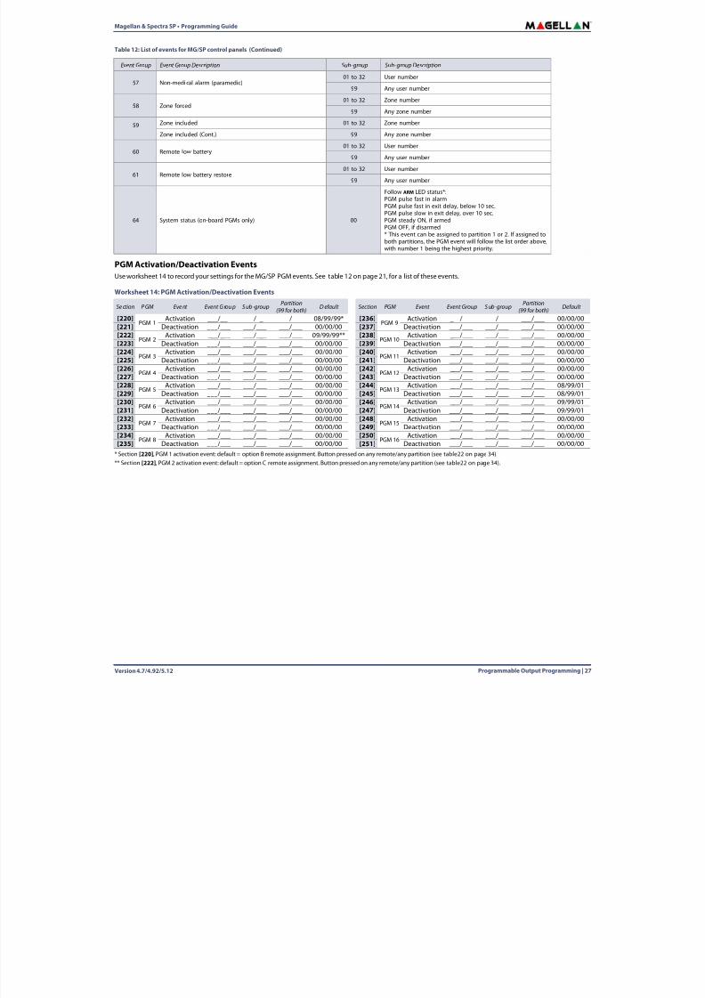
PGM Activation/Deactivation EventsUse worksheet 14 to record your settings for the MG/SP PGM events. See table 12 on page 21 , for a list of these events.
* Section [220] , PGM 1 activation event: default = option B remote assignment. Button pressed on any remote/any partition (see table22 on page 34 ).** Section [222] , PGM 2 activation event: default = option C remote assignment. Button pressed on any remote/any partition (see table22 on page 34 ).
57 Non-medical alarm (paramedic)01 to 32 User number
99 Any user number
58 Zone forced01 to 32 Zone number
99 Any zone number
59 Zone included 01 to 32 Zone number
Zone included (Cont.) 99 Any zone number
60 Remote low battery01 to 32 User number
99 Any user number
61 Remote low battery restore01 to 32 User number
99 Any user number
64 System status (on-board PGMs only) 00
Follow ARM LED status*:PGM pulse fast in alarmPGM pulse fast in exit delay, below 10 sec.PGM pulse slow in exit delay, over 10 sec.PGM steady ON, if armedPGM OFF, if disarmed* This event can be assigned to partition 1 or 2. If assigned toboth partitions, the PGM event will follow the list order above,with number 1 being the highest priority.
Worksheet 14: PGM Activation/Deactivation Events
Section PGM Event Event Group Sub-group Partition(99 for both) D efault Section PGM Event Event Group S ub-group Partition
(99 for both) Default
[220]PGM 1
Activation ___/___ ___/___ ___/___ 08/99/99* [236]PGM 9
Activation ___/___ ___/___ ___/___ 00/00/00[221] Deactivation ___/___ ___/___ ___/___ 00/00/00 [237] Deactivation ___/___ ___/___ ___/___ 00/00/00[222]
PGM 2Activation ___/___ ___/___ ___/___ 09/99/99** [238]
PGM 10Activation ___/___ ___/___ ___/___ 00/00/00
[223] Deactivation ___/___ ___/___ ___/___ 00/00/00 [239] Deactivation ___/___ ___/___ ___/___ 00/00/00[224]
PGM 3Activation ___/___ ___/___ ___/___ 00/00/00 [240]
PGM 11Activation ___/___ ___/___ ___/___ 00/00/00
[225] Deactivation ___/___ ___/___ ___/___ 00/00/00 [241] Deactivation ___/___ ___/___ ___/___ 00/00/00[226]
PGM 4Activation ___/___ ___/___ ___/___ 00/00/00 [242]
PGM 12Activation ___/___ ___/___ ___/___ 00/00/00
[227] Deactivation ___/___ ___/___ ___/___ 00/00/00 [243] Deactivation ___/___ ___/___ ___/___ 00/00/00[228]
PGM 5Activation ___/___ ___/___ ___/___ 00/00/00 [244]
PGM 13Activation ___/___ ___/___ ___/___ 08/99/01
[229] Deactivation ___/___ ___/___ ___/___ 00/00/00 [245] Deactivation ___/___ ___/___ ___/___ 08/99/01
[230] PGM 6 Activation ___/___ ___/___ ___/___ 00/00/00 [246] PGM 14 Activation ___/___ ___/___ ___/___ 09/99/01[231] Deactivation ___/___ ___/___ ___/___ 00/00/00 [247] Deactivation ___/___ ___/___ ___/___ 09/99/01[232]
PGM 7Activation ___/___ ___/___ ___/___ 00/00/00 [248]
PGM 15Activation ___/___ ___/___ ___/___ 00/00/00
[233] Deactivation ___/___ ___/___ ___/___ 00/00/00 [249] Deactivation ___/___ ___/___ ___/___ 00/00/00[234]
PGM 8Activation ___/___ ___/___ ___/___ 00/00/00 [250]
PGM 16Activation ___/___ ___/___ ___/___ 00/00/00
[235] Deactivation ___/___ ___/___ ___/___ 00/00/00 [251] Deactivation ___/___ ___/___ ___/___ 00/00/00
Table 12: List of events for MG/SP control panels (Continued)
Event Group Event Group Description Sub-group Sub-group Description
8/10/2019 Mgsp Ep27 Web
http://slidepdf.com/reader/full/mgsp-ep27-web 28/72
Version 4.7/4.92/5.1228 | Programmable Output Programming
Magellan & Spectra SP • Programming Guide
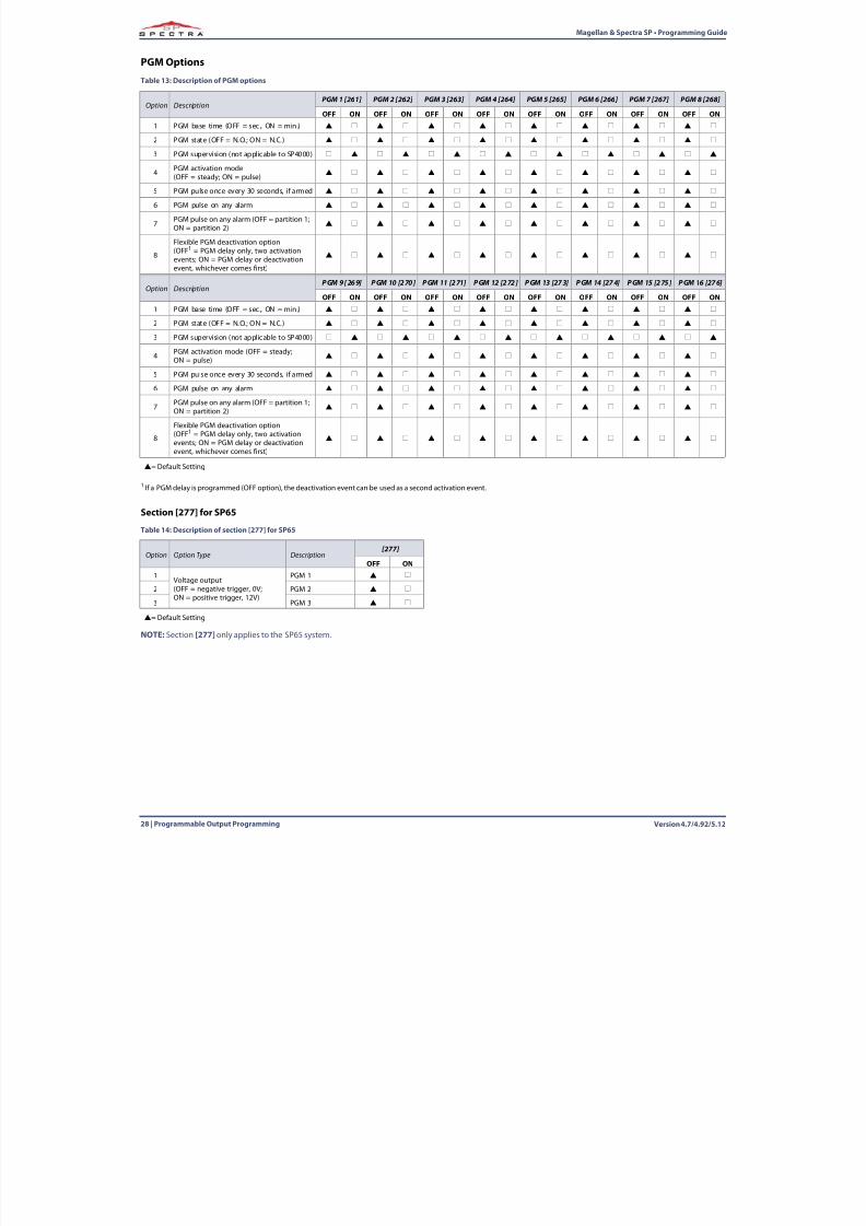
PGM Options
1 If a PGM delay is programmed (OFF option), the deactivation event can be used as a second activation event.
Section [277] for SP65
NOTE:Section [277] only applies to the SP65 system.
Table 13: Description of PGM options
Option DescriptionPGM 1 [261] PGM 2 [262] PGM 3 [263] PGM 4 [264] PGM 5 [265] PGM 6 [266] PGM 7 [267] PGM 8 [268]
OFF ON OFF ON OFF ON OFF ON OFF ON OFF ON OFF ON OFF ON1 PGM base time (OFF = sec., ON = min.)
2 PGM state (OFF = N.O.; ON = N.C.)
3 PGM supervision (not applicable to SP4000)
4 PGM activation mode(OFF = steady; ON = pulse)
5 PGM pulse once every 30 seconds, if armed
6 PGM pulse on any alarm
7 PGM pulse on any alarm (OFF = partition 1;ON = partition 2)
8
Flexible PGM deactivation option(OFF1 = PGM delay only, two activationevents; ON = PGM delay or deactivationevent, whichever comes first)
Option DescriptionPGM 9 [269] PGM 10 [270] PGM 11 [271] PGM 12 [272] PGM 13 [273] PGM 14 [274] PGM 15 [275] PGM 16 [276]
OFF ON OFF ON OFF ON OFF ON OFF ON OFF ON OFF ON OFF ON1 PGM base time (OFF = sec., ON = min.)
2 PGM state (OFF = N.O.; ON = N.C.)
3 PGM supervision (not applicable to SP4000)
4 PGM activation mode (OFF = steady;ON = pulse)
5 PGM pulse once every 30 seconds, if armed
6 PGM pulse on any alarm
7 PGM pulse on any alarm (OFF = partition 1;ON = partition 2)
8
Flexible PGM deactivation option(OFF1 = PGM delay only, two activationevents; ON = PGM delay or deactivationevent, whichever comes first)
= Default Setting
Table 14: Description of section [277] for SP65
Option Option Type Description[277]
OFF ON1
Voltage output(OFF = negative trigger, 0V;ON = positive trigger, 12V)
PGM 1
2 PGM 2
3 PGM 3
= Default Setting
8/10/2019 Mgsp Ep27 Web
http://slidepdf.com/reader/full/mgsp-ep27-web 29/72
Magellan & Spectra SP • Programming Guide
Version 4.7/4.92/5.12 Programmable Output Programming | 29
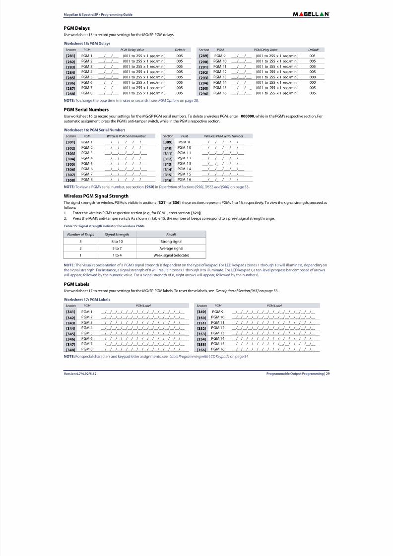
PGM DelaysUse worksheet 15 to record your settings for the MG/SP PGM delays.
NOTE: To change the base time (minutes or seconds), see PGM Options on page 28 .
PGM Serial NumbersUse worksheet 16 to record your settings for the MG/SP PGM serial numbers. To delete a wireless PGM, enter 000000 , while in the PGM’s respective section. Forautomatic assignment, press the PGM’s anti-tamper switch, while in the PGM’s respective section.
NOTE: To view a PGM’s serial number, see section [960] in Description of Sections [950], [955], and [960] on page 53 .
Wireless PGM Signal Strength The signal strength for wireless PGMs is visible in sections [321] to [336] ; these sections represent PGMs 1 to 16, respectively. To view the signal strength, proceed asfollows:1. Enter the wireless PGM’s respective section (e.g., for PGM1, enter section [321] ).2. Press the PGM’s anti-tamper switch. As shown in table 15 , the number of beeps correspond to a preset signal strength range.
NOTE: The visual representation of a PGM’s signal strength is dependent on the type of keypad. For LED keypads, zones 1 through 10 will illuminate, depending onthe signal strength. For instance, a signal strength of 8 will result in zones 1 through 8 to illuminate. For LCD keypads, a ten-level progress bar composed of arrowswill appear, followed by the numeric value. For a signal strength of 8, eight arrows will appear, followed by the number 8.
PGM LabelsUse worksheet 17 to record your settings for the MG/SP PGM labels. To reset these labels, see Description of Section [965] on page 53 .
NOTE:For special characters and keypad letter assignments, see Label Programming with LCD Keypads on page 54 .
Worksheet 15: PGM DelaysSection PGM PGM Delay Value Default Section PGM PGM Delay Value Default
[281] PGM 1 ___/___/___ (001 to 255 x 1 sec./min.) 005 [289] PGM 9 ___/___/___ (001 to 255 x 1 sec./min.) 005
[282] PGM 2 ___/___/___ (001 to 255 x 1 sec./min.) 005 [290] PGM 10 ___/___/___ (001 to 255 x 1 sec./min.) 005
[283] PGM 3 ___/___/___ (001 to 255 x 1 sec./min.) 005 [291] PGM 11 ___/___/___ (001 to 255 x 1 sec./min.) 005
[284] PGM 4 ___/___/___ (001 to 255 x 1 sec./min.) 005 [292] PGM 12 ___/___/___ (001 to 255 x 1 sec./min.) 005
[285] PGM 5 ___/___/___ (001 to 255 x 1 sec./min.) 005 [293] PGM 13 ___/___/___ (001 to 255 x 1 sec./min.) 000
[286] PGM 6 ___/___/___ (001 to 255 x 1 sec./min.) 005 [294] PGM 14 ___/___/___ (001 to 255 x 1 sec./min.) 000
[287] PGM 7 ___/___/___ (001 to 255 x 1 sec./min.) 005 [295] PGM 15 ___/___/___ (001 to 255 x 1 sec./min.) 005
[288] PGM 8 ___/___/___ (001 to 255 x 1 sec./min.) 005 [296] PGM 16 ___/___/___ (001 to 255 x 1 sec./min.) 005
Worksheet 16: PGM Serial NumbersSection PGM Wireless PGM Serial Number Section PGM Wireless PGM Serial Number
[301] PGM 1 ___/___/___/___/___/___ [309] PGM 9 ___/___/___/___/___/___
[302]PGM 2 ___/___/___/___/___/___
[310]PGM 10 ___/___/___/___/___/___
[303] PGM 3 ___/___/___/___/___/___ [311] PGM 11 ___/___/___/___/___/___
[304] PGM 4 ___/___/___/___/___/___ [312] PGM 12 ___/___/___/___/___/___
[305] PGM 5 ___/___/___/___/___/___ [313] PGM 13 ___/___/___/___/___/___
[306] PGM 6 ___/___/___/___/___/___ [314] PGM 14 ___/___/___/___/___/___
[307] PGM 7 ___/___/___/___/___/___ [315] PGM 15 ___/___/___/___/___/___
[308] PGM 8 ___/___/___/___/___/___ [316] PGM 16 ___/___/___/___/___/___
Table 15: Signal strength indicator for wireless PGMs
Number of Beeps Signal Strength Result
3 8 to 10 Strong signal
2 5 to 7 Average signal
1 1 to 4 Weak signal (relocate)
Worksheet 17: PGM LabelsSection PGM PGM Label Section PGM PGM Label
[341] PGM 1 __/__/__/__/__/__/__/__/__/__/__/__/__/__/__/__ [349] PGM 9 __/__/__/__/__/__/__/__/__/__/__/__/__/__/__/__
[342] PGM 2 __/__/__/__/__/__/__/__/__/__/__/__/__/__/__/__ [350] PGM 10 __/__/__/__/__/__/__/__/__/__/__/__/__/__/__/__
[343] PGM 3 __/__/__/__/__/__/__/__/__/__/__/__/__/__/__/__ [351] PGM 11 __/__/__/__/__/__/__/__/__/__/__/__/__/__/__/__
[344] PGM 4 __/__/__/__/__/__/__/__/__/__/__/__/__/__/__/__ [352] PGM 12 __/__/__/__/__/__/__/__/__/__/__/__/__/__/__/__
[345] PGM 5 __/__/__/__/__/__/__/__/__/__/__/__/__/__/__/__ [353] PGM 13 __/__/__/__/__/__/__/__/__/__/__/__/__/__/__/__
[346] PGM 6 __/__/__/__/__/__/__/__/__/__/__/__/__/__/__/__ [354] PGM 14 __/__/__/__/__/__/__/__/__/__/__/__/__/__/__/__
[347] PGM 7 __/__/__/__/__/__/__/__/__/__/__/__/__/__/__/__ [355] PGM 15 __/__/__/__/__/__/__/__/__/__/__/__/__/__/__/__
[348] PGM 8 __/__/__/__/__/__/__/__/__/__/__/__/__/__/__/__ [356] PGM 16 __/__/__/__/__/__/__/__/__/__/__/__/__/__/__/__
8/10/2019 Mgsp Ep27 Web
http://slidepdf.com/reader/full/mgsp-ep27-web 30/72
Version 4.7/4.92/5.1230 | User Programming
Magellan & Spectra SP • Programming Guide
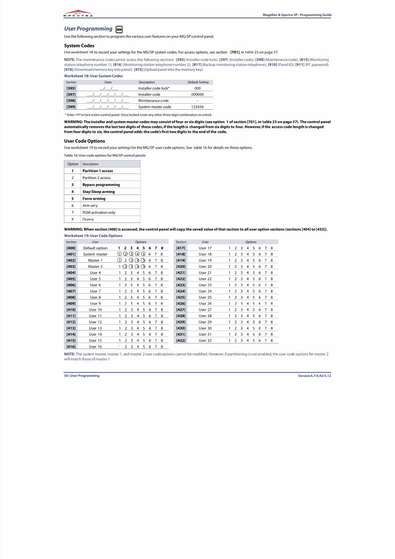
User ProgrammingUse the following section to program the various user features on your MG/SP control panel.
System CodesUse worksheet 18 to record your settings for the MG/SP system codes. For access options, see section [701] , in table 25 on page 37 .
NOTE: The maintenance code cannot access the following sections: [395] (Installer code lock); [397] (Installer code); [398] (Maintenance code); [815] (Monitoringstation telephone number 1); [816] (Monitoring station telephone number 2); [817] (Backup monitoring station telephone); [910] (Panel ID); [911] (PC password);[970] (Download memory key into panel); [975] (Upload panel into the memory key).
WARNING: The installer and system master codes may consist of four or six digits (see option 1 of section [701], in table 25 on page 37 ). The control panelautomatically removes the last two digits of these codes, if the length is changed from six digits to four. However, if the access code length is changedfrom four digits to six, the control panel adds the code’s first two digits to the end of the code.
User Code OptionsUse worksheet 19 to record your settings for the MG/SP user code options. See table 16 for details on these options.
WARNING: When section [400] is accessed, the control panel will copy the saved value of that section to all user option sections (sections [404] to [432]).
NOTE: The system master, master 1, and master 2 user code options cannot be modified. However, if partitioning is not enabled, the user code options for master 2will match those of master 1.
Worksheet 18: User System CodesSection Data Description Default Setting
[395] ___/___/___ Installer code lock* 000
[397] ___/___/___/___/___/___ Installer code 000000
[398] ___/___/___/___/___/___ Maintenance code -
[399] ___/___/___/___/___/___ System master code 123456
* Enter 147 to lock entire control panel. Once locked, enter any other three-digit combination to unlock.
Table 16: User code options for MG/SP control panels
Option Description
1 Partition 1 access
2 Partition 2 access
3 Bypass programming
4 Stay/Sleep arming
5 Force arming
6 Arm only
7 PGM activation only
8 Duress
Worksheet 19: User Code OptionsSection User Options Section User Options
[400] Default option 1 2 3 4 5 6 7 8 [417] User 17 1 2 3 4 5 6 7 8
[401] System master 1 2 3 4 5 6 7 8 [418] User 18 1 2 3 4 5 6 7 8
[402] Master 1 1 2 3 4 5 6 7 8 [419] User 19 1 2 3 4 5 6 7 8
[403] Master 2 1 2 3 4 5 6 7 8 [420] User 20 1 2 3 4 5 6 7 8
[404] User 4 1 2 3 4 5 6 7 8 [421] User 21 1 2 3 4 5 6 7 8
[405] User 5 1 2 3 4 5 6 7 8 [422] User 22 1 2 3 4 5 6 7 8
[406] User 6 1 2 3 4 5 6 7 8 [423] User 23 1 2 3 4 5 6 7 8
[407] User 7 1 2 3 4 5 6 7 8 [424] User 24 1 2 3 4 5 6 7 8
[408] User 8 1 2 3 4 5 6 7 8 [425] User 25 1 2 3 4 5 6 7 8
[409] User 9 1 2 3 4 5 6 7 8 [426] User 26 1 2 3 4 5 6 7 8[410] User 10 1 2 3 4 5 6 7 8 [427] User 27 1 2 3 4 5 6 7 8
[411] User 11 1 2 3 4 5 6 7 8 [428] User 28 1 2 3 4 5 6 7 8
[412] User 12 1 2 3 4 5 6 7 8 [429] User 29 1 2 3 4 5 6 7 8
[413] User 13 1 2 3 4 5 6 7 8 [430] User 30 1 2 3 4 5 6 7 8
[414] User 14 1 2 3 4 5 6 7 8 [431] User 31 1 2 3 4 5 6 7 8
[415] User 15 1 2 3 4 5 6 7 8 [432] User 32 1 2 3 4 5 6 7 8
[416] User 16 1 2 3 4 5 6 7 8
8/10/2019 Mgsp Ep27 Web
http://slidepdf.com/reader/full/mgsp-ep27-web 31/72
Magellan & Spectra SP • Programming Guide
Version 4.7/4.92/5.12 Wireless Repeater Programming (RPT1) | 31
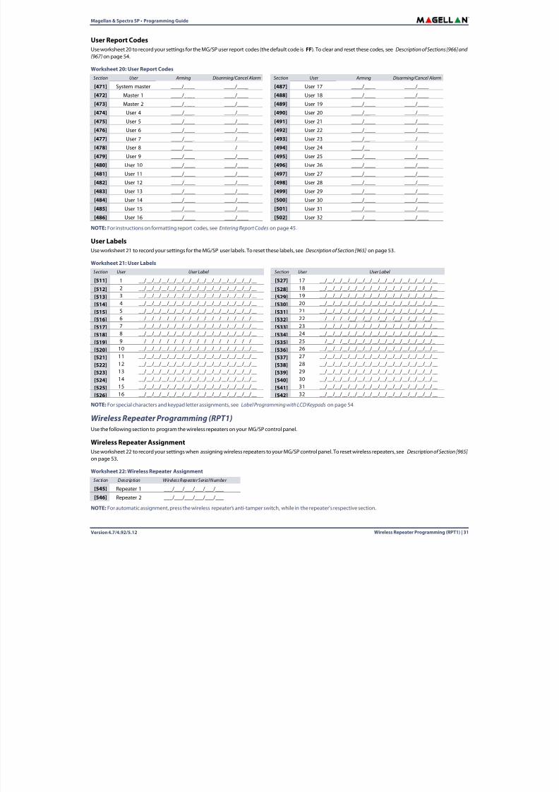
User Report CodesUse worksheet 20 to record your settings for the MG/SP user report codes (the default code is FF). To clear and reset these codes, see Description of Sections [966] and[967] on page 54.
NOTE:For instructions on formatting report codes, see Entering Report Codes on page 45 .
User LabelsUse worksheet 21 to record your settings for the MG/SP user labels. To reset these labels, see Description of Section [965] on page 53 .
NOTE:For special characters and keypad letter assignments, see Label Programming with LCD Keypads on page 54 .
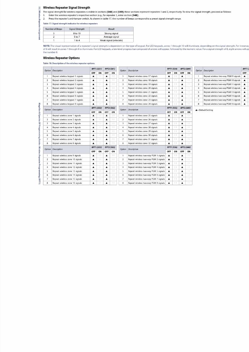
Wireless Repeater Programming (RPT1)Use the following section to program the wireless repeaters on your MG/SP control panel.
Wireless Repeater AssignmentUse worksheet 22 to record your settings when assigning wireless repeaters to your MG/SP control panel. To reset wireless repeaters, see Description of Section [965]on page 53 .
NOTE:For automatic assignment, press the wireless repeater’s anti-tamper switch, while in the repeater’s respective section.
Worksheet 20: User Report CodesSection User Arming Disarming/Cancel Alarm Section User Arming Disarming/Cancel Alarm
[471] System master ____/____ ____/____ [487] User 17 ____/____ ____/____
[472] Master 1 ____/____ ____/____ [488] User 18 ____/____ ____/____
[473] Master 2 ____/____ ____/____ [489] User 19 ____/____ ____/____[474] User 4 ____/____ ____/____ [490] User 20 ____/____ ____/____
[475] User 5 ____/____ ____/____ [491] User 21 ____/____ ____/____
[476] User 6 ____/____ ____/____ [492] User 22 ____/____ ____/____
[477] User 7 ____/____ ____/____ [493] User 23 ____/____ ____/____
[478] User 8 ____/____ ____/____ [494] User 24 ____/____ ____/____
[479] User 9 ____/____ ____/____ [495] User 25 ____/____ ____/____
[480] User 10 ____/____ ____/____ [496] User 26 ____/____ ____/____
[481] User 11 ____/____ ____/____ [497] User 27 ____/____ ____/____
[482] User 12 ____/____ ____/____ [498] User 28 ____/____ ____/____
[483] User 13 ____/____ ____/____ [499] User 29 ____/____ ____/____
[484] User 14 ____/____ ____/____ [500] User 30 ____/____ ____/____
[485] User 15 ____/____ ____/____ [501] User 31 ____/____ ____/____
[486] User 16 ____/____ ____/____ [502] User 32 ____/____ ____/____
Worksheet 21: User LabelsSection User User Label Section User User Label
[511] 1 __/__/__/__/__/__/__/__/__/__/__/__/__/__/__/__ [527] 17 __/__/__/__/__/__/__/__/__/__/__/__/__/__/__/__
[512] 2 __/__/__/__/__/__/__/__/__/__/__/__/__/__/__/__ [528] 18 __/__/__/__/__/__/__/__/__/__/__/__/__/__/__/__
[513] 3 __/__/__/__/__/__/__/__/__/__/__/__/__/__/__/__ [529] 19 __/__/__/__/__/__/__/__/__/__/__/__/__/__/__/__
[514] 4 __/__/__/__/__/__/__/__/__/__/__/__/__/__/__/__ [530] 20 __/__/__/__/__/__/__/__/__/__/__/__/__/__/__/__
[515] 5 __/__/__/__/__/__/__/__/__/__/__/__/__/__/__/__ [531] 21 __/__/__/__/__/__/__/__/__/__/__/__/__/__/__/__
[516] 6 __/__/__/__/__/__/__/__/__/__/__/__/__/__/__/__ [532] 22 __/__/__/__/__/__/__/__/__/__/__/__/__/__/__/__[517] 7 __/__/__/__/__/__/__/__/__/__/__/__/__/__/__/__ [533] 23 __/__/__/__/__/__/__/__/__/__/__/__/__/__/__/__
[518] 8 __/__/__/__/__/__/__/__/__/__/__/__/__/__/__/__ [534] 24 __/__/__/__/__/__/__/__/__/__/__/__/__/__/__/__
[519] 9 __/__/__/__/__/__/__/__/__/__/__/__/__/__/__/__ [535] 25 __/__/__/__/__/__/__/__/__/__/__/__/__/__/__/__
[520] 10 __/__/__/__/__/__/__/__/__/__/__/__/__/__/__/__ [536] 26 __/__/__/__/__/__/__/__/__/__/__/__/__/__/__/__
[521] 11 __/__/__/__/__/__/__/__/__/__/__/__/__/__/__/__ [537] 27 __/__/__/__/__/__/__/__/__/__/__/__/__/__/__/__
[522] 12 __/__/__/__/__/__/__/__/__/__/__/__/__/__/__/__ [538] 28 __/__/__/__/__/__/__/__/__/__/__/__/__/__/__/__
[523] 13 __/__/__/__/__/__/__/__/__/__/__/__/__/__/__/__ [539] 29 __/__/__/__/__/__/__/__/__/__/__/__/__/__/__/__
[524] 14 __/__/__/__/__/__/__/__/__/__/__/__/__/__/__/__ [540] 30 __/__/__/__/__/__/__/__/__/__/__/__/__/__/__/__
[525] 15 __/__/__/__/__/__/__/__/__/__/__/__/__/__/__/__ [541] 31 __/__/__/__/__/__/__/__/__/__/__/__/__/__/__/__
[526] 16 __/__/__/__/__/__/__/__/__/__/__/__/__/__/__/__ [542] 32 __/__/__/__/__/__/__/__/__/__/__/__/__/__/__/__
Worksheet 22: Wireless Repeater AssignmentSection Description Wireless Repeater Serial Number
[545] Repeater 1 ___/___/___/___/___/___
[546] Repeater 2 ___/___/___/___/___/___
8/10/2019 Mgsp Ep27 Web
http://slidepdf.com/reader/full/mgsp-ep27-web 32/72
8/10/2019 Mgsp Ep27 Web
http://slidepdf.com/reader/full/mgsp-ep27-web 33/72
Magellan & Spectra SP • Programming Guide
Version 4.7/4.92/5.12 Wireless Keypad Programming | 33
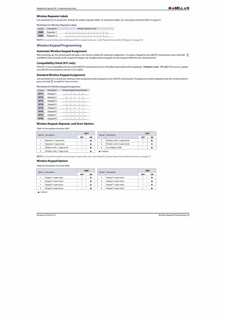
Wireless Repeater LabelsUse worksheet 23 to record your settings for wireless repeater labels. To reset these labels, see Description of Section [965] on page 53 .
NOTE:For special characters and keypad letter assignments, see Label Programming with LCD Keypads on page 54 .
Wireless Keypad Programming
Automatic Wireless Keypad AssignmentAfter powering-up, the control panel will open a ten-minute window for automatic assignment. To assign a keypad to your MG/SP control panel, press and hold and BYP for three seconds on the respective keypad. Up to eight wireless keypads can be assigned within this ten-minute period.
Compatibility Check (K37 only)If the K37 is not compatible with the current MG/SP control panel version, the following trouble will be displayed: [TROUBLE: FLASH] [17: ON]. If this occurs, updateyour MG/SP control panel to version 3.2 or higher.
Standard Wireless Keypad AssignmentUse worksheet 24 to record your settings, when assigning wireless keypads to your MG/SP control panel. To assign your wireless keypads, enter the serial number orpress and hold and BYP for three seconds.
Wireless Keypad, Repeater, and Siren Options
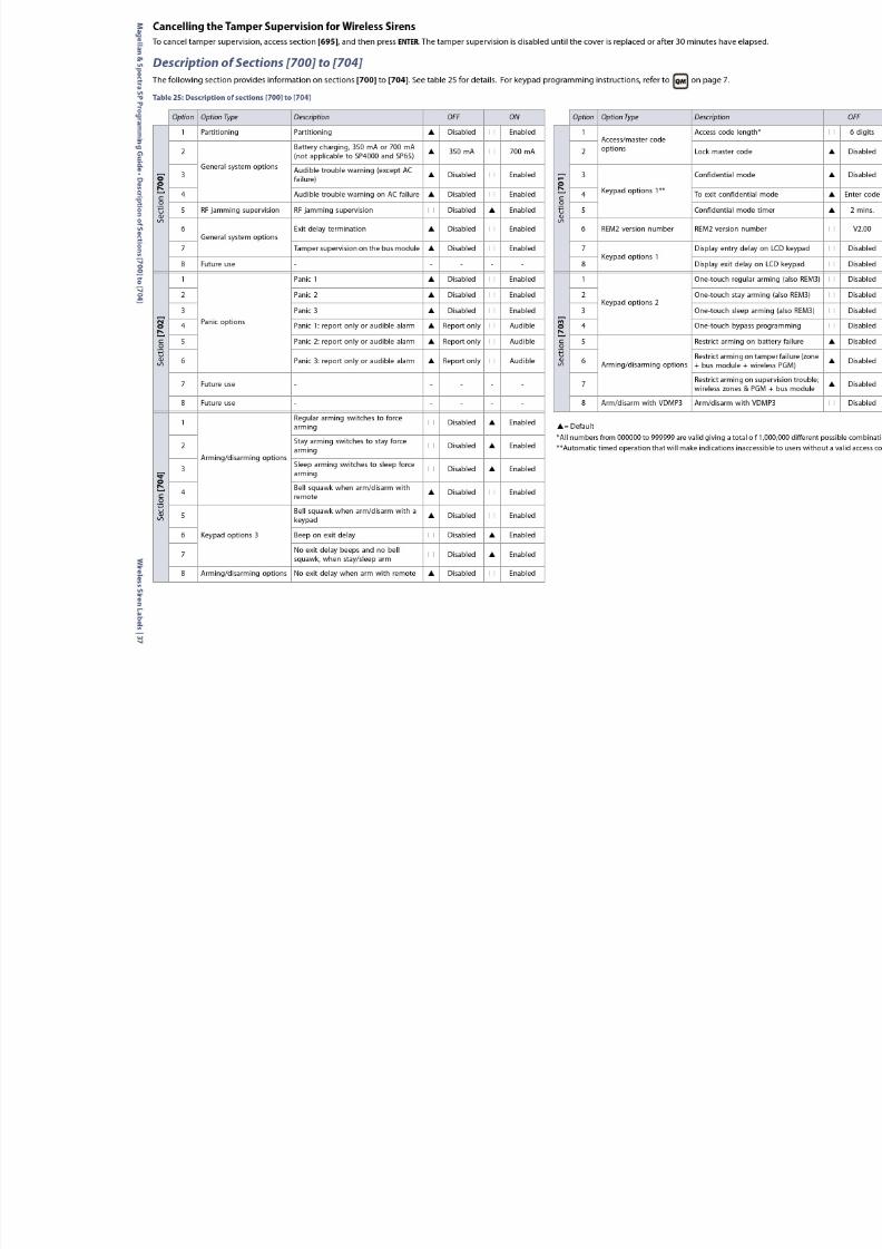
NOTE: To cancel the wireless siren tamper supervision, see Cancelling the Tamper Supervision for Wireless Sirens on page 37.
Wireless Keypad Options
Worksheet 23: Wireless Repeater LabelsSection D escription Wireless Repeater Label
[568] Repeater 1 __/__/__/__/__/__/__/__/__/__/__/__/__/__/__
[569] Repeater 2 __/__/__/__/__/__/__/__/__/__/__/__/__/__/__
Worksheet 24: Wireless Keypad AssignmentSection Description Wireless Keypad Serial Number
[571] Keypad 1 ___/___/___/___/___/___
[572] Keypad 2 ___/___/___/___/___/___
[573] Keypad 3 ___/___/___/___/___/___
[574] Keypad 4 ___/___/___/___/___/___
[575] Keypad 5 ___/___/___/___/___/___
[576] Keypad 6 ___/___/___/___/___/___
[577] Keypad 7 ___/___/___/___/___/___
[578] Keypad 8 ___/___/___/___/___/___
Table 19: Description of section [587]
Option Description[587]
Option Description[587]
OFF ON OFF ON1 Repeater 1 supervision 5 Wireless siren 3 supervision
2 Repeater 2 supervision 6 Wireless siren 4 supervision
3 Wireless siren 1 supervision 8 Live display mode
4 Wireless siren 2 supervision = Default
Table 20: Description of section [588]
Option Description
[588]
Option Description
[588]
OFF ON OFF ON1 Keypad 1 supervision 5 Keypad 5 supervision
2 Keypad 2 supervision 6 Keypad 6 supervision
3 Keypad 3 supervision 7 Keypad 7 supervision
4 Keypad 4 supervision 8 Keypad 8 supervision
= Default
8/10/2019 Mgsp Ep27 Web
http://slidepdf.com/reader/full/mgsp-ep27-web 34/72
Version 4.7/4.92/5.1234 | Remote Control Programming
Magellan & Spectra SP • Programming Guide
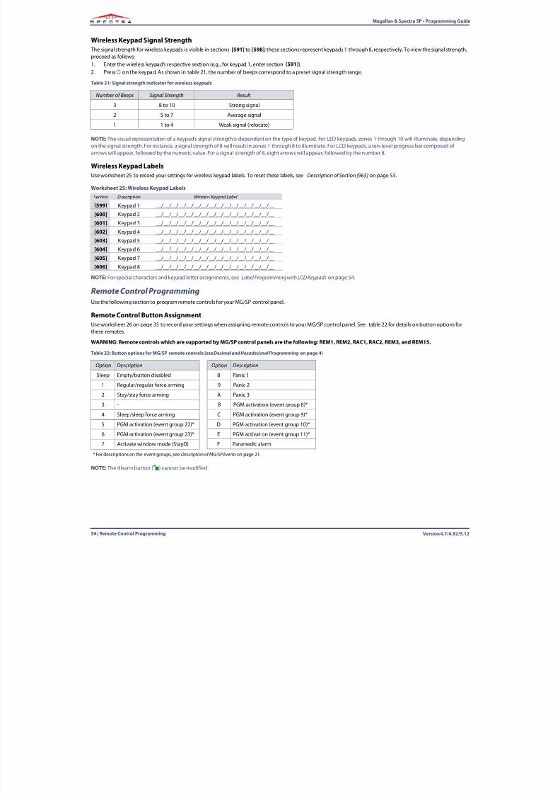
Wireless Keypad Signal Strength The signal strength for wireless keypads is visible in sections [591] to [598] ; these sections represent keypads 1 through 8, respectively. To view the signal strength,proceed as follows:1. Enter the wireless keypad’s respective section (e.g., for keypad 1, enter section [591] ).2. Press on the keypad. As shown in table 21 , the number of beeps correspond to a preset signal strength range.
NOTE: The visual representation of a keypad’s signal strength is dependent on the type of keypad. For LED keypads, zones 1 through 10 will illuminate, dependingon the signal strength. For instance, a signal strength of 8 will result in zones 1 through 8 to illuminate. For LCD keypads, a ten-level progress bar composed ofarrows will appear, followed by the numeric value. For a signal strength of 8, eight arrows will appear, followed by the number 8.
Wireless Keypad LabelsUse worksheet 25 to record your settings for wireless keypad labels. To reset these labels, see Description of Section [965] on page 53 .
NOTE:For special characters and keypad letter assignments, see Label Programming with LCD Keypads on page 54 .
Remote Control ProgrammingUse the following section to program remote controls for your MG/SP control panel.
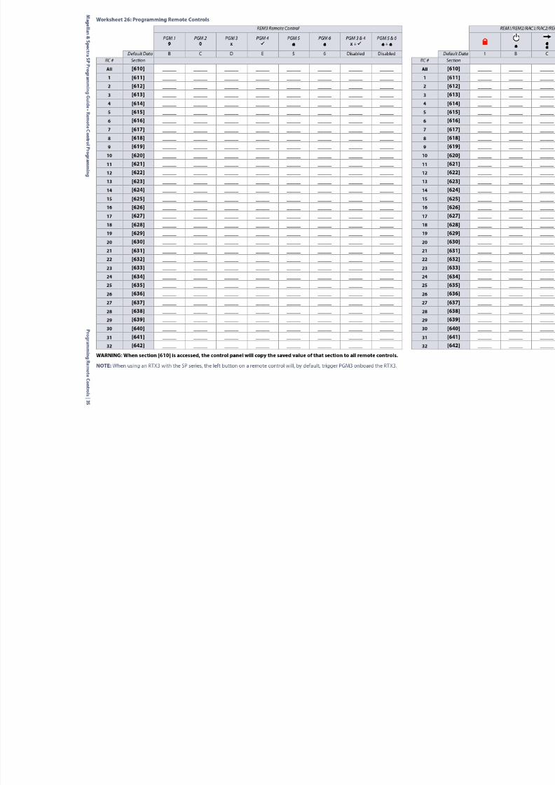
Remote Control Button AssignmentUse worksheet 26 on page 35 to record your settings when assigning remote controls to your MG/SP control panel. See table 22 for details on button options forthese remotes.
WARNING: Remote controls which are supported by MG/SP control panels are the following: REM1, REM2, RAC1, RAC2, REM3, and REM15.
NOTE: The disarm button ( ) cannot be modified.
Table 21: Signal strength indicator for wireless keypads
Number of Beeps Signal Strength Result
3 8 to 10 Strong signal2 5 to 7 Average signal
1 1 to 4 Weak signal (relocate)
Worksheet 25: Wireless Keypad LabelsSection D escription Wireless Keypad Label
[599] Keypad 1 __/__/__/__/__/__/__/__/__/__/__/__/__/__/__/__
[600] Keypad 2 __/__/__/__/__/__/__/__/__/__/__/__/__/__/__/__[601] Keypad 3 __/__/__/__/__/__/__/__/__/__/__/__/__/__/__/__
[602] Keypad 4 __/__/__/__/__/__/__/__/__/__/__/__/__/__/__/__
[603] Keypad 5 __/__/__/__/__/__/__/__/__/__/__/__/__/__/__/__
[604] Keypad 6 __/__/__/__/__/__/__/__/__/__/__/__/__/__/__/__
[605] Keypad 7 __/__/__/__/__/__/__/__/__/__/__/__/__/__/__/__
[606] Keypad 8 __/__/__/__/__/__/__/__/__/__/__/__/__/__/__/__
Table 22: Button options for MG/SP remote controls (see Decimal and Hexadecimal Programming on page 4 )
Option Description Option Description
Sleep Empty/button disabled 8 Panic 1
1 Regular/regular force arming 9 Panic 2
2 Stay/stay force arming A Panic 3
3 - B PGM activation (event group 8)*
4 Sleep/sleep force arming C PGM activation (event group 9)*
5 PGM activation (event group 22)* D PGM activation (event group 10)*
6 PGM activation (event group 23)* E PGM activation (event group 11)*
7 Activate window mode (StayD) F Paramedic alarm
* For descriptions on the event groups, see Description of MG/SP Eventson page 21 .
8/10/2019 Mgsp Ep27 Web
http://slidepdf.com/reader/full/mgsp-ep27-web 35/72
8/10/2019 Mgsp Ep27 Web
http://slidepdf.com/reader/full/mgsp-ep27-web 36/72
Version 4.7/4.92/5.1236 | Wireless Siren Programming
Magellan & Spectra SP • Programming Guide
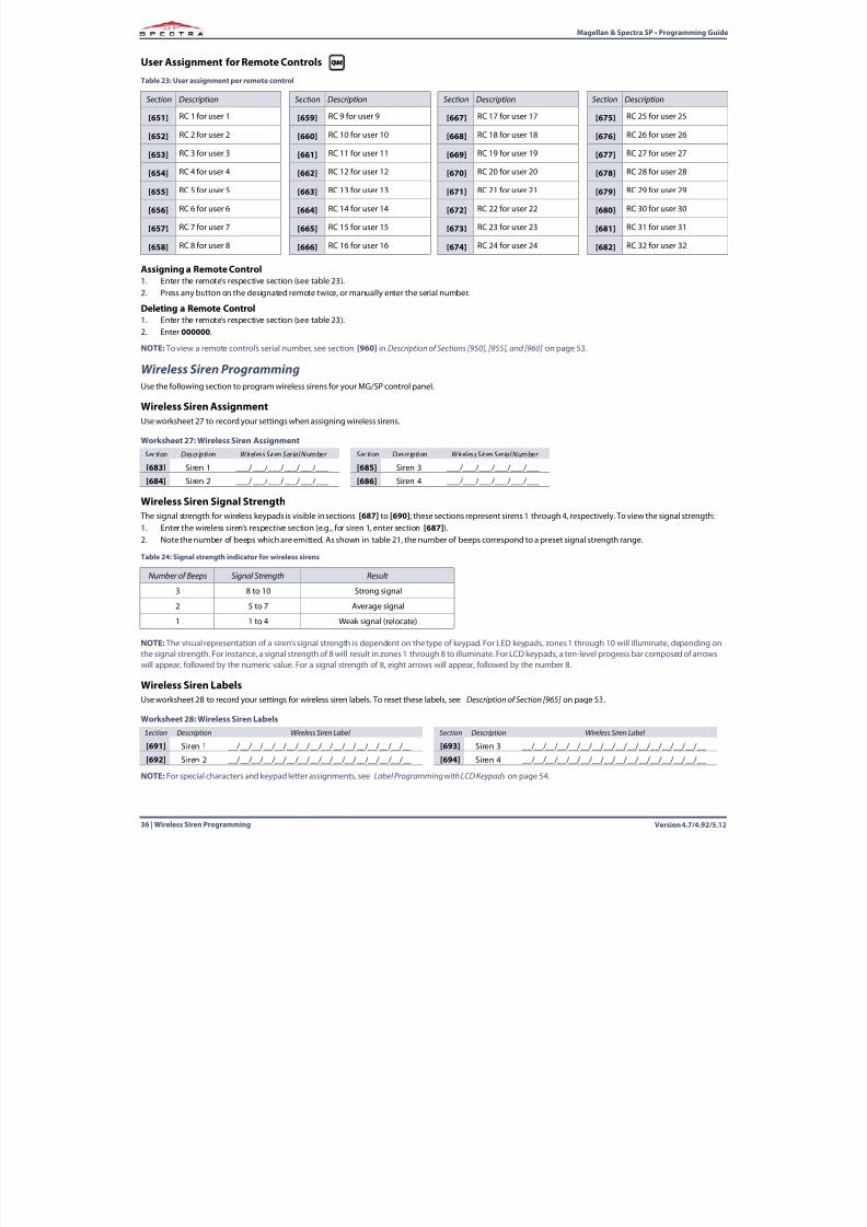
User Assignment for Remote Controls
Assigning a Remote Control1. Enter the remote’s respective section (see table 23 ).2. Press any button on the designated remote twice, or manually enter the serial number.
Deleting a Remote Control1. Enter the remote’s respective section (see table 23 ).
2. Enter 000000 .NOTE: To view a remote control’s serial number, see section [960] in Description of Sections [950], [955], and [960] on page 53 .
Wireless Siren ProgrammingUse the following section to program wireless sirens for your MG/SP control panel.
Wireless Siren AssignmentUse worksheet 27 to record your settings when assigning wireless sirens.
Wireless Siren Signal Strength The signal strength for wireless keypads is visible in sections [687] to [690] ; these sections represent sirens 1 through 4, respectively. To view the signal strength:1. Enter the wireless siren’s respective section (e.g., for siren 1, enter section [687] ).2. Note the number of beeps which are emitted. As shown in table 21 , the number of beeps correspond to a preset signal strength range.
NOTE: The visual representation of a siren’s signal strength is dependent on the type of keypad. For LED keypads, zones 1 through 10 will illuminate, depending onthe signal strength. For instance, a signal strength of 8 will result in zones 1 through 8 to illuminate. For LCD keypads, a ten-level progress bar composed of arrows
will appear, followed by the numeric value. For a signal strength of 8, eight arrows will appear, followed by the number 8.
Wireless Siren LabelsUse worksheet 28 to record your settings for wireless siren labels. To reset these labels, see Description of Section [965] on page 53 .
NOTE:For special characters and keypad letter assignments, see Label Programming with LCD Keypads on page 54 .
Table 23: User assignment per remote control
Section Description Section Description Section Description Section Description
[651] RC 1 for user 1 [659] RC 9 for user 9 [667] RC 17 for user 17 [675] RC 25 for user 25
[652] RC 2 for user 2 [660] RC 10 for user 10 [668] RC 18 for user 18 [676] RC 26 for user 26
[653] RC 3 for user 3 [661] RC 11 for user 11 [669] RC 19 for user 19 [677] RC 27 for user 27
[654] RC 4 for user 4 [662] RC 12 for user 12 [670] RC 20 for user 20 [678] RC 28 for user 28
[655] RC 5 for user 5 [663] RC 13 for user 13 [671] RC 21 for user 21 [679] RC 29 for user 29
[656] RC 6 for user 6 [664] RC 14 for user 14 [672] RC 22 for user 22 [680] RC 30 for user 30
[657] RC 7 for user 7 [665] RC 15 for user 15 [673] RC 23 for user 23 [681] RC 31 for user 31
[658] RC 8 for user 8 [666] RC 16 for user 16 [674] RC 24 for user 24 [682] RC 32 for user 32
Worksheet 27: Wireless Siren AssignmentSection Description Wireless Siren Serial Number Section Description Wireless Siren Serial Number
[683] Siren 1 ___/___/___/___/___/___ [685] Siren 3 ___/___/___/___/___/___
[684] Siren 2 ___/___/___/___/___/___ [686] Siren 4 ___/___/___/___/___/___
Table 24: Signal strength indicator for wireless sirens
Number of Beeps Signal Strength Result
3 8 to 10 Strong signal
2 5 to 7 Average signal
1 1 to 4 Weak signal (relocate)
Worksheet 28: Wireless Siren LabelsSection Description Wireless Siren Label Section Description Wireless Siren Label
[691] Siren 1 __/__/__/__/__/__/__/__/__/__/__/__/__/__/__/__ [693] Siren 3 __/__/__/__/__/__/__/__/__/__/__/__/__/__/__/__
[692] Siren 2 __/__/__/__/__/__/__/__/__/__/__/__/__/__/__/__ [694] Siren 4 __/__/__/__/__/__/__/__/__/__/__/__/__/__/__/__
8/10/2019 Mgsp Ep27 Web
http://slidepdf.com/reader/full/mgsp-ep27-web 37/72
8/10/2019 Mgsp Ep27 Web
http://slidepdf.com/reader/full/mgsp-ep27-web 38/72
Version 4.7/4.92/5.1238 | Zone Options
Magellan & Spectra SP • Programming Guide
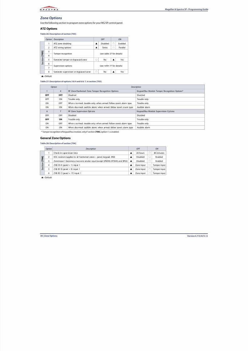
Zone OptionsUse the following section to program zone options for your MG/SP control panel.
ATZ Options
General Zone Options
Table 26: Description of section [705]
Option Description OFF ON
S e c t i o n
[ 7 0 5 ]
1 ATZ zone doubling Disabled Enabled
2 ATZ wiring options Series Parallel
3 Tamper recognition (see table 27 for details)
4
5 Generate tamper on bypassed zone No Yes
6Supervision options (see table 27 for details)
7
8 Generate supervision on bypassed zone No Yes
= Default
Table 27: Description of options 3 & 4 and 6 & 7, in section [705]
Option Description
3 4 RF Zone/Hardwired Zone Tamper Recognition Options Keypad/Bus Module Tamper Recognition Options*
OFF OFF Disabled Disabled
OFF ON Trouble only Trouble only
ON OFF When disarmed: trouble only; when armed: follow zone’s alarm type Trouble only
ON ON When disarmed: audible alarm; when armed: follow zone’s alarm type Audible alarm
6 7 RF Zone Supervision Options Keypad/Bus Module Supervision Options
OFF OFF Disabled Disabled
OFF ON Trouble only Trouble only
ON OFF When disarmed: trouble only; when armed: follow zone’s alarm type Trouble only
ON ON When disarmed: audible alarm; when armed: follow zone’s alarm type Audible alarm
* Tamper recognition of keypad/bus module, only if section [700] , option 7, is enabled.
Table 28: Description of section [706]
Option Description OFF ON
S e c t i o n
[ 7 0 6 ]
1 Check-in supervision time 24 hours 80 minutes
2 EOL resistors (applies to all hardwired zones – panel, keypad, ZX8) Disabled Enabled
3 Zone input 1 becomes a two-wire smoke input (except SP4000, SP5500, and SP65) Disabled Enabled
4 ZX8 ID A (panel + 1) input 1 Zone input Tamper input
5 ZX8 ID B (panel + 9) input 1 Zone input Tamper input
6 ZX8 ID C (panel + 17) input 1 Zone input Tamper input
= Default
8/10/2019 Mgsp Ep27 Web
http://slidepdf.com/reader/full/mgsp-ep27-web 39/72
Magellan & Spectra SP • Programming Guide
Version 4.7/4.92/5.12 System Timers | 39
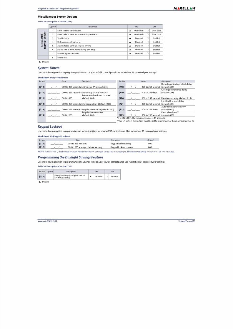
Miscellaneous System Options
System TimersUse the following section to program system timers on your MG/SP control panel. Use worksheet 29 to record your settings.
Keypad Lockout Use the following section to program keypad lockout settings for your MG/SP control panel. Use worksheet 30 to record your settings.
NOTE:For EN 50131, the keypad lockout value must be set between three and ten attempts. The minimum delay to lock must be two minutes.
Programming the Daylight Savings FeatureUse the following section to program Daylight Savings Time on your MG/SP control panel. Use worksheet 31 to record your settings.
Table 29: Description of section [708]
Option Description OFF ON
S e c t i o n
[ 7 0 8 ]
E N 5 0
1 3 1 O P T I O N S 1 Enter code to view trouble One-touch Enter code
2 Enter code to view alarm in memory/event list One-touch Enter code
3 Trouble latch Disabled Enabled
4 Bell squawk on Installer in Disabled Enabled
5 Acknowledge trouble(s) before arming Disabled Enabled
6 Do not arm if zone opens during exit delay Disabled Enabled
7 Disable ‘Bypass and Arm’ Disabled Enabled
8 Future use
= Default
Worksheet 29: System TimersSection Data Description Section Data Description
[710] ___/___/___ 000 to 255 seconds Entry delay 1* (default: 045) [718] ___/___/___ 000 to 255 secondsRemote panic disarm lock delay(default: 000)
[711] ___/___/___ 000 to 255 seconds Entry delay 2* (default: 045) [719] ___/___/___ 000 to 255 daysClosing delinquency delay(default: 000)
[712] ___/___/___ 000 to 015Auto-zone shutdown counter(default: 005) [720] ___/___/___ 000 to 255 seconds Flex-instant delay (default: 015)
[713] ___/___/___ 000 to 255 seconds Intellizone delay (default: 048) [721] ___/___/___ 000 to 255 secondsFor StayD: re-arm delay(default: 005)
[714] ___/___/___ 000 to 255 minutes Recycle alarm delay (default: 000) [722] ___/___/___ 000 to 255 timesAuto trouble shutdown**(default:000)
[715] ___/___/___ 000 to 255Recycle alarm counter(default: 000) [723] ___/___/___ 000 to 255 seconds
Panic shutdown**(default:000)
* For EN 50131, the maximum value is 45 seconds.** For EN 50131, the section must be set to a minimum of 3 and a maximum of 10
Worksheet 30: Keypad LockoutSection Data Description Default
[716] ___/___/___ 000 to 255 minutes Keypad lockout delay 000
[717] ___/___/___ 000 to 255 attempts before locking Keypad lockout counter 000
Table 30: Description of section [730]
Section Option Description OFF ON
[730] 1 Daylight savings (not applicable to
SP4000 and SP65) Disabled Enabled
= Default
8/10/2019 Mgsp Ep27 Web
http://slidepdf.com/reader/full/mgsp-ep27-web 40/72
Version 4.7/4.92/5.1240 | Partition Programming
Magellan & Spectra SP • Programming Guide
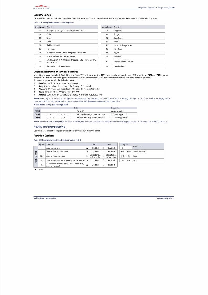
Country Codes Table 31 lists countries and their respective codes. This information is required when programming section [731] (see worksheet 31 for details).
Customized Daylight Savings FeaturesIn addition to using the default Daylight Saving Time (DST) settings in section [731] , you can also set a customized DST. In sections [732] and [733] , you canprogram DST starting and ending periods, respectively. Both these sections recognize five different entries, consisting of two digits each.All entries must be made in the following order:1. Month : 01 to 12, where 01 represents January2. Date : 01 to 31, where 01 represents the first day of the month3. Day : 00 to 07, where 00 is the default setting and 01 represents Sunday4. Hours : 00 to 23, where 00 represents 12:00 AM5. Minutes : 00 only, where 00 represents the top of the hour (e.g., 12: 00 AM)
NOTE:If the Day value is set to 00, it is ignored and the DST change will only respect the Date value. If the Day setting is set to a value other than 00 (e.g., 03 for Tuesday), the DST time change will occur on the first Tuesday following the programmed Date value.
NOTE:If sections [732] and [733] have been modified, but you want to revert to a standard DST code, change all settings in sections [732] and [733] to 00.
Partition ProgrammingUse the following section to program partitions on your MG/SP control panel.
Partition Options
Table 31: Country codes for MG/SP control panels
Input Value Country Input Value Country
00 Mexico; St. Johns; Bahamas; Turks and Caicos 10 Chatham
01 Cuba 11 Tonga
02 Brazil 12 Iraq; Syria
03 Chile 13 Israel
04 Falkland Islands 14 Lebanon; Kyrgyzstan
05 Paraguay 15 Palestine
06 European Union; United Kingdom; Greenland 16 Egypt
07 Russia and surrounding countries 17 Namibia
08South Australia; Victoria; Australian Capital Territory; NewSouth Wales
18 Canada; United States
09 Tasmania; Lord Howe Island 19 New Zealand
Worksheet 31: Daylight Savings TimeSection Data Description
[731] ___/___ 00 to 99 Country code
[732] __/__/__/__/__/__/__/__/__/__ Month-date-day-hours-minutes DST staring period
[733] __/__/__/__/__/__/__/__/__/__ Month-date-day-hours-minutes DST ending period
Table 32: Description of partition 1 options (section [741])
Option Description OFF ON OptionDescription
S e c t
i o n
[ 7 4 1 ]
1 Auto-arm on time Disabled Enabled 3 4
2 Auto-arm on no movement Disabled Enabled OFF OFF Regular (default)
3 & 4 Auto-arm arming mode See options 3& 4, on right
See options 3& 4, on right OFF ON Sleep
5 Switch to stay arming, if no entry zone is opened Disabled Enabled ON OFF Stay
6 Follow zones become entry delay 2, when delayzone is bypassed
Disabled Enabled
= Default
8/10/2019 Mgsp Ep27 Web
http://slidepdf.com/reader/full/mgsp-ep27-web 41/72
Magellan & Spectra SP • Programming Guide
Version 4.7/4.92/5.12 SMS and Bus Module Programming | 41
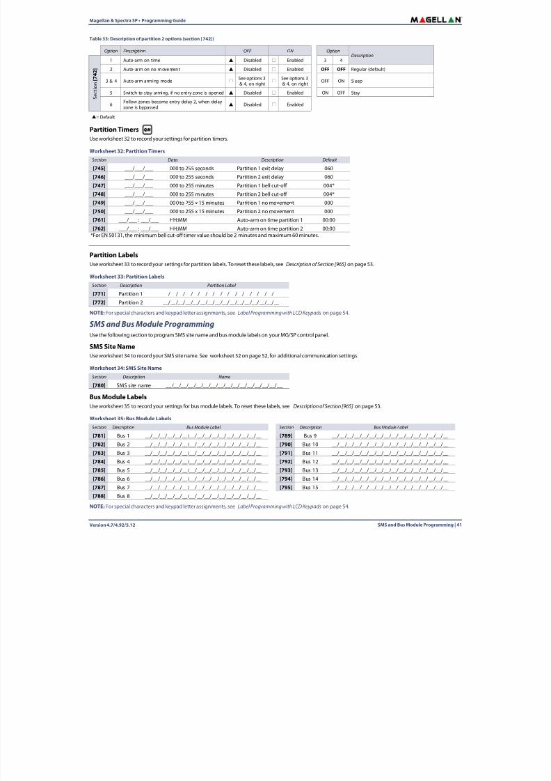
Partition TimersUse worksheet 32 to record your settings for partition timers.
Partition LabelsUse worksheet 33 to record your settings for partition labels. To reset these labels, see Description of Section [965] on page 53 .
NOTE:For special characters and keypad letter assignments, see Label Programming with LCD Keypads on page 54 .
SMS and Bus Module ProgrammingUse the following section to program SMS site name and bus module labels on your MG/SP control panel.
SMS Site NameUse worksheet 34 to record your SMS site name. See worksheet 52 on page 52, for additional communication settings.
Bus Module LabelsUse worksheet 35 to record your settings for bus module labels. To reset these labels, see Description of Section [965] on page 53 .
NOTE:For special characters and keypad letter assignments, see Label Programming with LCD Keypads on page 54 .
Table 33: Description of partition 2 options (section [742])
Option Description OFF ON OptionDescription
S e c t i o n
[ 7 4 2 ]
1 Auto-arm on time Disabled Enabled 3 4
2 Auto-arm on no movement Disabled Enabled OFF OFF Regular (default)
3 & 4 Auto-arm arming mode See options 3& 4, on right
See options 3& 4, on right OFF ON Sleep
5 Switch to stay arming, if no entry zone is opened Disabled Enabled ON OFF Stay
6Follow zones become entry delay 2, when delayzone is bypassed Disabled Enabled
= Default
Worksheet 32: Partition TimersSection Data Description Default
[745] ___/___/___ 000 to 255 seconds Partition 1 exit delay 060
[746] ___/___/___ 000 to 255 seconds Partition 2 exit delay 060
[747] ___/___/___ 000 to 255 minutes Partition 1 bell cut-off 004*
[748] ___/___/___ 000 to 255 minutes Partition 2 bell cut-off 004*
[749] ___/___/___ 000 to 255 x 15 minutes Par tition 1 no movement 000
[750] ___/___/___ 000 to 255 x 15 minutes Partition 2 no movement 000[761] ___/___ : ___/___ HH:MM Auto-arm on time partition 1 00:00
[762] ___/___ : ___/___ HH:MM Auto-arm on time partition 2 00:00*For EN 50131, the minimum bell cut-off timer value should be 2 minutes and maximum 60 minutes.
Worksheet 33: Partition LabelsSection Description Partition Label
[771] Partition 1 __/__/__/__/__/__/__/__/__/__/__/__/__/__/__/__
[772] Partition 2 __/__/__/__/__/__/__/__/__/__/__/__/__/__/__/__
Worksheet 34: SMS Site NameSection Description Name
[780] SMS site name __/__/__/__/__/__/__/__/__/__/__/__/__/__/__/__
Worksheet 35: Bus Module LabelsSection Description Bus Module Label Section Description Bus Module Label
[781] Bus 1 __/__/__/__/__/__/__/__/__/__/__/__/__/__/__/__ [789] Bus 9 __/__/__/__/__/__/__/__/__/__/__/__/__/__/__/__
[782] Bus 2 __/__/__/__/__/__/__/__/__/__/__/__/__/__/__/__ [790] Bus 10 __/__/__/__/__/__/__/__/__/__/__/__/__/__/__/__
[783] Bus 3 __/__/__/__/__/__/__/__/__/__/__/__/__/__/__/__ [791] Bus 11 __/__/__/__/__/__/__/__/__/__/__/__/__/__/__/__
[784] Bus 4 __/__/__/__/__/__/__/__/__/__/__/__/__/__/__/__ [792] Bus 12 __/__/__/__/__/__/__/__/__/__/__/__/__/__/__/__
[785] Bus 5 __/__/__/__/__/__/__/__/__/__/__/__/__/__/__/__ [793] Bus 13 __/__/__/__/__/__/__/__/__/__/__/__/__/__/__/__
[786] Bus 6 __/__/__/__/__/__/__/__/__/__/__/__/__/__/__/__ [794] Bus 14 __/__/__/__/__/__/__/__/__/__/__/__/__/__/__/__
[787] Bus 7 __/__/__/__/__/__/__/__/__/__/__/__/__/__/__/__ [795] Bus 15 __/__/__/__/__/__/__/__/__/__/__/__/__/__/__/__
[788] Bus 8 __/__/__/__/__/__/__/__/__/__/__/__/__/__/__/__
8/10/2019 Mgsp Ep27 Web
http://slidepdf.com/reader/full/mgsp-ep27-web 42/72
8/10/2019 Mgsp Ep27 Web
http://slidepdf.com/reader/full/mgsp-ep27-web 43/72
Magellan & Spectra SP • Programming Guide
Version 4.7/4.92/5.12 Communication Programming | 43
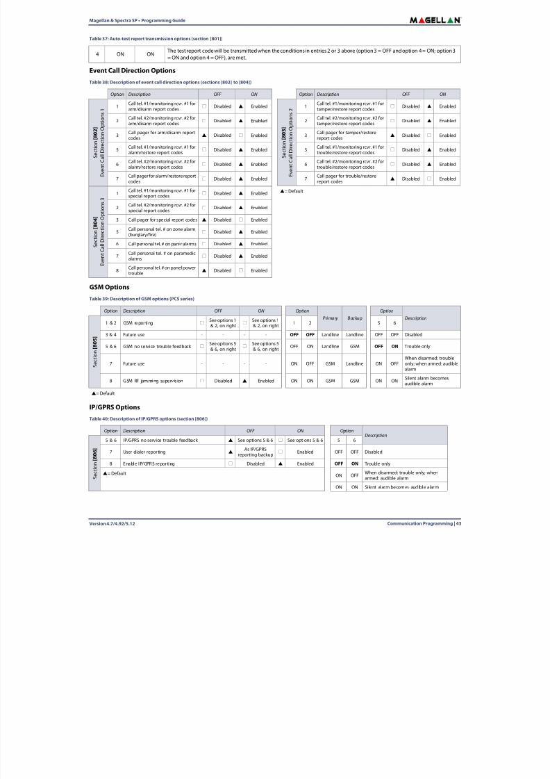
Event Call Direction Options
GSM Options
IP/GPRS Options
4 ON ON The test report code will be transmitted when the conditions in entries 2 or 3 above (option 3 = OFF and option 4 = ON; option 3= ON and option 4 = OFF), are met.
Table 38: Description of event call direction options (sections [802] to [804])
Option Description OFF ON Option Description OFF ON
S e c t i o n
[ 8 0 2 ]
E v e n t
C a l l D
i r e c t i o n
O p t i o n s
1 1 Call tel. #1/monitoring rcvr. #1 forarm/disarm report codes Disabled Enabled
S e c t i o n
[ 8 0 3 ]
E v e n t
C a l l D
i r e c t i o n
O p t i o n s
2 1 Call tel. #1/monitoring rcvr. #1 fortamper/restore report codes Disabled Enabled
2 Call tel. #2/monitoring rcvr. #2 forarm/disarm report codes
Disabled Enabled 2 Call tel. #2/monitoring rcvr. #2 fortamper/restore report codes
Disabled Enabled
3 Call pager for arm/disarm reportcodes
Disabled Enabled 3 Call pager for tamper/restorereport codes
Disabled Enabled
5 Call tel. #1/monitoring rcvr. #1 foralarm/restore report codes
Disabled Enabled 5 Call tel. #1/monitoring rcvr. #1 fortrouble/restore report codes
Disabled Enabled
6 Call tel. #2/monitoring rcvr. #2 foralarm/restore report codes
Disabled Enabled 6 Call tel. #2/monitoring rcvr. #2 fortrouble/restore report codes
Disabled Enabled
7 Call pager for alarm/restore reportcodes
Disabled Enabled 7 Call pager for trouble/restorereport codes
Disabled Enabled
S e c t i o n
[ 8 0 4 ]
E v e n t
C a
l l D i r e c t i o n
O p t i o n s
31 Call tel. #1/monitoring rcvr. #1 for
special report codes Disabled Enabled
= Default
2 Call tel. #2/monitoring rcvr. #2 for
special report codes Disabled Enabled
3 Call pager for special report codes Disabled Enabled
5 Call personal tel. # on zone alarm(burglary/fire)
Disabled Enabled
6 Call personal tel. # on panic alarms Disabled Enabled
7 Call personal tel. # on paramedicalarms
Disabled Enabled
8 Call personal tel. # on panel powertrouble
Disabled Enabled
Table 39: Description of GSM options (PCS series)
Option Description OFF ON OptionPrimary Backup
OptionDescription
S e c t i o n
[ 8 0 5 ]
1 & 2 GSM reporting See options 1& 2, on right
See options 1& 2, on right 1 2 5 6
3 & 4 Future use - - - - OFF OFF Landline Landline OFF OFF Disabled
5 & 6 GSM no service trouble feedback See options 5& 6, on right
See options 5& 6, on right OFF ON Landline GSM OFF ON Trouble only
7 Future use - - - - ON OFF GSM Landline ON OFFWhen disarmed: troubleonly; when armed: audiblealarm
8 GSM RF jamming supervis ion Disabled Enabled ON ON GSM GSM ON ON Silent alarm becomesaudible alarm
= Default
Table 40: Description of IP/GPRS options (section [806])Option Description OFF ON Option
Description
S e c t i o n
[ 8 0 6 ]
5 & 6 IP/GPRS no service trouble feedback See options 5 & 6 See options 5 & 6 5 6
7 User dialer repor ting As IP/GPRSreporting backup
Enabled OFF OFF Disabled
8 Enable IP/GPRS reporting Disabled Enabled OFF ON Trouble only
= Default ON OFF When disarmed: trouble only; whenarmed: audible alarm
ON ON Silent alarm becomes audible a larm
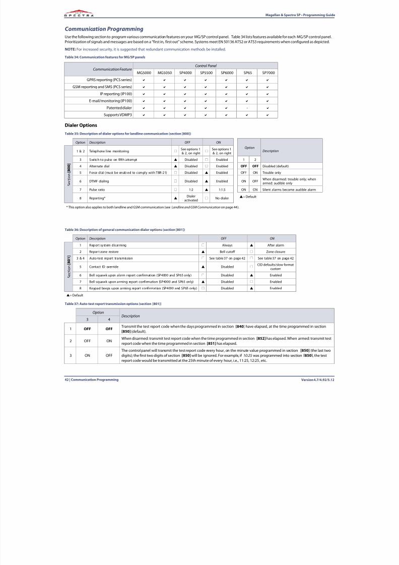
Table 37: Auto-test report transmission options (section [801])
8/10/2019 Mgsp Ep27 Web
http://slidepdf.com/reader/full/mgsp-ep27-web 44/72
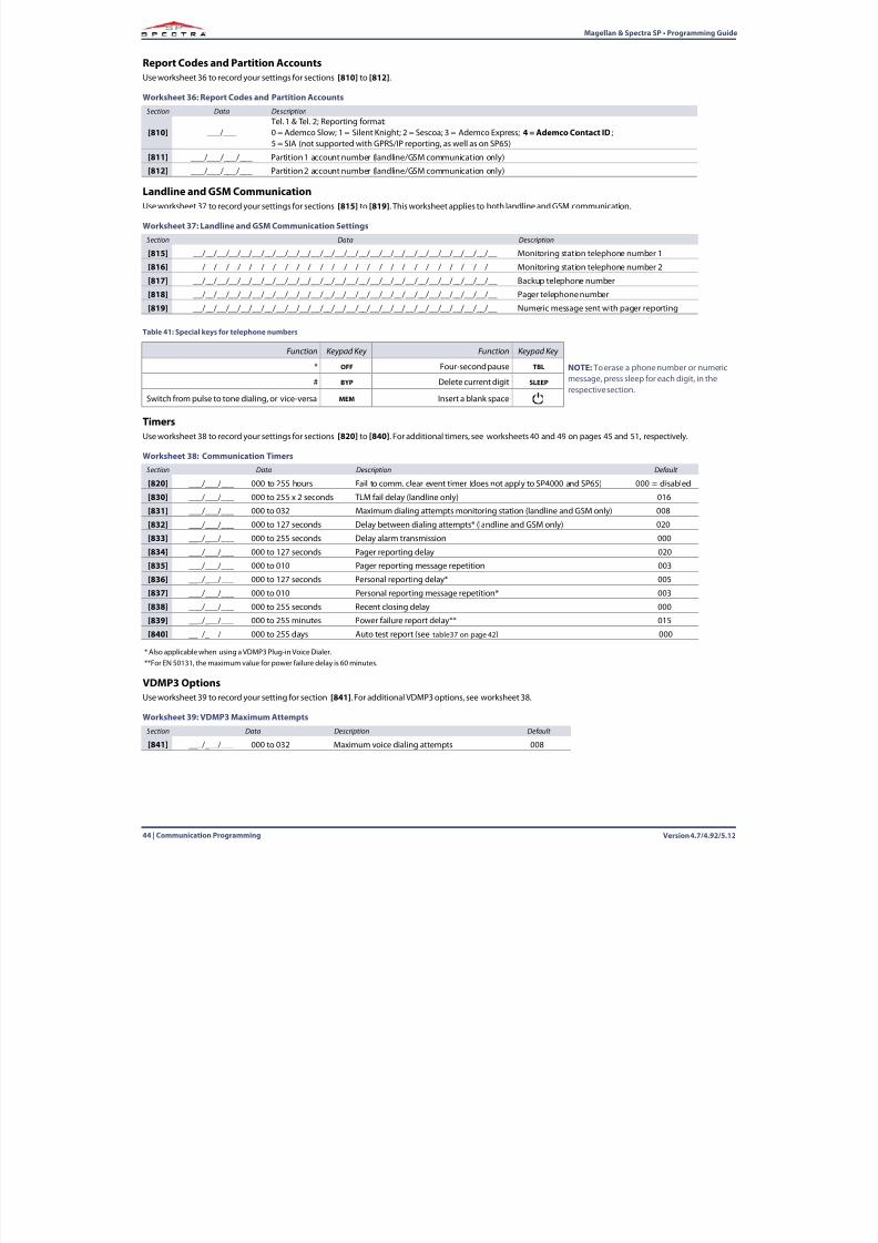
Version 4.7/4.92/5.1244 | Communication Programming
Magellan & Spectra SP • Programming Guide
Report Codes and Partition AccountsUse worksheet 36 to record your settings for sections [810] to [812] .
Landline and GSM CommunicationUse worksheet 37 to record your settings for sections [815] to [819] . This worksheet applies to both landline and GSM communication.
TimersUse worksheet 38 to record your settings for sections [820] to [840] . For additional timers, see worksheets 40 and 49 on pages 45 and 51, respectively.
VDMP3 OptionsUse worksheet 39 to record your setting for section [841] . For additional VDMP3 options, see worksheet 38.
Worksheet 36: Report Codes and Partition AccountsSection Data Description
[810] ___/___ Tel. 1 & Tel. 2; Reporting format:0 = Ademco Slow; 1 = Silent Knight; 2 = Sescoa; 3 = Ademco Express; 4 = Ademco Contact ID ; 5 = SIA (not supported with GPRS/IP reporting, as well as on SP65)
[811] ___/___/___/___ Partition 1 account number (landline/GSM communication only)
[812] ___/___/___/___ Partition 2 account number (landline/GSM communication only)
Worksheet 37: Landline and GSM Communication SettingsSection Data Description
[815] __/__/__/__/__/__/__/__/__/__/__/__/__/__/__/__/__/__/__/__/__/__/__/__/__/__ Monitoring station telephone number 1
[816] __/__/__/__/__/__/__/__/__/__/__/__/__/__/__/__/__/__/__/__/__/__/__/__/__/__ Monitoring station telephone number 2
[817] __/__/__/__/__/__/__/__/__/__/__/__/__/__/__/__/__/__/__/__/__/__/__/__/__/__ Backup telephone number
[818] __/__/__/__/__/__/__/__/__/__/__/__/__/__/__/__/__/__/__/__/__/__/__/__/__/__ Pager telephone number
[819] __/__/__/__/__/__/__/__/__/__/__/__/__/__/__/__/__/__/__/__/__/__/__/__/__/__ Numeric message sent with pager reporting
Table 41: Special keys for telephone numbersFunction Keypad Key Function Keypad Key
NOTE: To erase a phone number or numericmessage, press sleep for each digit, in therespective section.
* OFF Four-second pause TBL
# BYP Delete current digit SLEEP
Switch from pulse to tone dialing, or vice-versa MEM Insert a blank space
Worksheet 38: Communication TimersSection Data Description Default
[820] ___/___/___ 000 to 255 hours Fail to comm. clear event timer (does not apply to SP4000 and SP65) 000 = disabled
[830] ___/___/___ 000 to 255 x 2 seconds TLM fail delay (landline only) 016
[831] ___/___/___ 000 to 032 Maximum dialing attempts monitoring station (landline and GSM only) 008
[832] ___/___/___ 000 to 127 seconds Delay between dialing attempts* (landline and GSM only) 020
[833] ___/___/___ 000 to 255 seconds Delay alarm transmission 000
[834] ___/___/___ 000 to 127 seconds Pager reporting delay 020
[835] ___/___/___ 000 to 010 Pager reporting message repetition 003
[836] ___/___/___ 000 to 127 seconds Personal reporting delay* 005
[837] ___/___/___ 000 to 010 Personal reporting message repetition* 003
[838] ___/___/___ 000 to 255 seconds Recent closing delay 000
[839] ___/___/___ 000 to 255 minutes Power failure report delay** 015
[840] ___/___/___ 000 to 255 days Auto test report (see table37 on page 42 ) 000
* Also applicable when using a VDMP3 Plug-in Voice Dialer.**For EN 50131, the maximum value for power failure delay is 60 minutes.
Worksheet 39: VDMP3 Maximum AttemptsSection Data Description Default
[841] ___/___/___ 000 to 032 Maximum voice dialing attempts 008
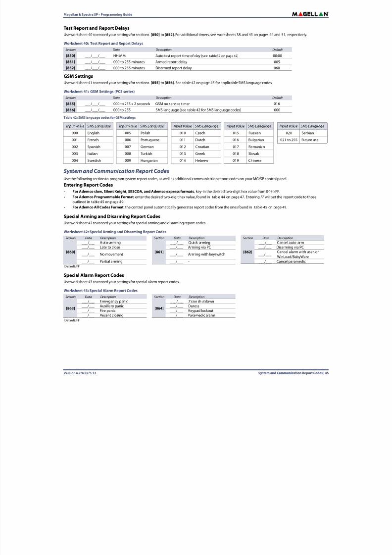
8/10/2019 Mgsp Ep27 Web
http://slidepdf.com/reader/full/mgsp-ep27-web 45/72
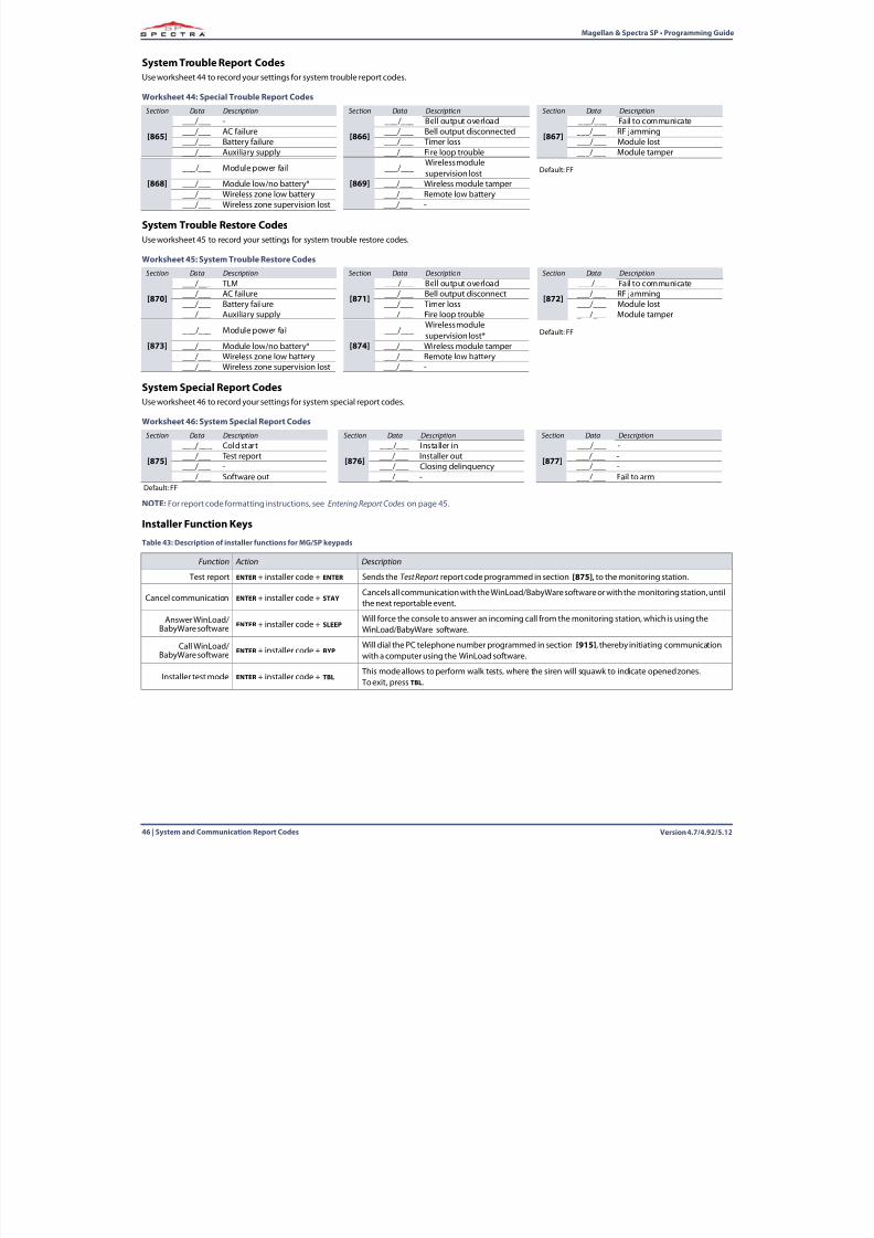
8/10/2019 Mgsp Ep27 Web
http://slidepdf.com/reader/full/mgsp-ep27-web 46/72
Version 4.7/4.92/5.1246 | System and Communication Report Codes
Magellan & Spectra SP • Programming Guide
System Trouble Report CodesUse worksheet 44 to record your settings for system trouble report codes.
System Trouble Restore CodesUse worksheet 45 to record your settings for system trouble restore codes.
System Special Report CodesUse worksheet 46 to record your settings for system special report codes.
NOTE:For report code formatting instructions, see Entering Report Codes on page 45.
Installer Function Keys
Worksheet 44: Special Trouble Report CodesSection Data Description Section Data Description Section Data Description
[865]
___/___ -
[866]
___/___ Bell output overload
[867]
___/___ Fail to communicate___/___ AC failure ___/___ Bell output disconnected ___/___ RF jamming___/___ Battery failure ___/___ Timer loss ___/___ Module lost___/___ Auxiliary supply ___/___ Fire loop trouble ___/___ Module tamper
[868]___/___ Module power fail
[869]___/___
Wireless modulesupervision lost Default: FF
___/___ Module low/no battery* ___/___ Wireless module tamper___/___ Wireless zone low battery ___/___ Remote low battery___/___ Wireless zone supervision lost ___/___ -
Worksheet 45: System Trouble Restore CodesSection Data Description Section Data Description Section Data Description
[870]
___/___ TLM
[871]
___/___ Bell output overload
[872]
___/___ Fail to communicate___/___ AC failure ___/___ Bell output disconnect ___/___ RF jamming___/___ Battery failure ___/___ Timer loss ___/___ Module lost___/___ Auxiliary supply ___/___ Fire loop trouble ___/___ Module tamper
[873]___/___ Module power fail
[874]___/___
Wireless module
supervision lost* Default: FF___/___ Module low/no battery* ___/___ Wireless module tamper___/___ Wireless zone low battery ___/___ Remote low battery___/___ Wireless zone supervision lost ___/___ -
Worksheet 46: System Special Report CodesSection Data Description Section Data Description Section Data Description
[875]
___/___ Cold start
[876]
___/___ Installer in
[877]
___/___ -___/___ Test report ___/___ Installer out ___/___ -___/___ - ___/___ Closing delinquency ___/___ -___/___ Software out ___/___ - ___/___ Fail to arm
Default: FF
Table 43: Description of installer functions for MG/SP keypads
Function Action Description
Test report ENTER + installer code + ENTER Sends the Test Report report code programmed in section [875] , to the monitoring station.
Cancel communication ENTER + installer code + STAYCancels all communication with the WinLoad/BabyWare software or with the monitoring station, untilthe next reportable event.
Answer WinLoad/BabyWare software ENTER + installer code + SLEEP
Will force the console to answer an incoming call from the monitoring station, which is using theWinLoad/BabyWare software.
Call WinLoad/BabyWare software ENTER + installer code + BYP
Will dial the PC telephone number programmed in section [915] , thereby initiating communicationwith a computer using the WinLoad software.
Installer test mode ENTER + installer code + TBL This mode allows to perform walk tests, where the siren will squawk to indicate opened zones. To exit, press TBL.
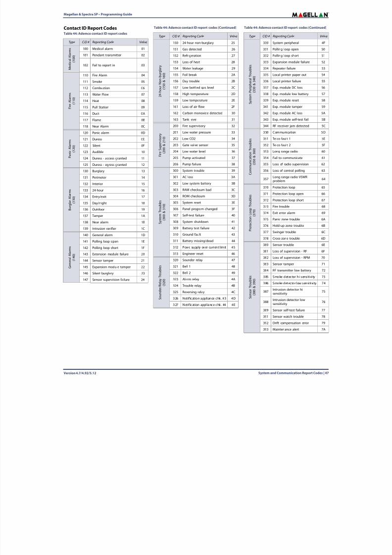
8/10/2019 Mgsp Ep27 Web
http://slidepdf.com/reader/full/mgsp-ep27-web 47/72
Magellan & Spectra SP • Programming Guide
Version 4.7/4.92/5.12 System and Communication Report Codes | 47
Contact ID Report CodesTable 44: Ademco contact ID report codes
Type CID # Reporting Code Value
M e
d i c a l A l a r m s
( 1 0 0 )
100 Medical alarm 01
101 Pendant transmitter 02
102 Fail to report in 03
F i r e A l a r m s
( 1 1 0 )
110 Fire Alarm 04
111 Smoke 05
112 Combustion 06
113 Water Flow 07
114 Heat 08
115 Pull Station 09
116 Duct 0A
117 Flame 0B
118 Near Alarm 0C
P a n
i c A l a r m s
( 1 2 0 )
120 Panic alarm 0D
121 Duress 0E
122 Silent 0F
123 Audible 10
124 Duress - access granted 11
125 Duress - egress granted 12
B u r g
l a r A l a r m s
( 1 3 0 )
130 Burglary 13
131 Perimeter 14
132 Interior 15
133 24-hour 16
134 Entry/exit 17
135 Day/night 18
136 Outdoor 19
137 Tamper 1A
138 Near alarm 1B
139 Intrusion verifier 1C
G e n e r a l
A l a r m s
( 1 4 0 )
140 General alarm 1D
141 Polling loop open 1E
142 Polling loop short 1F
143 Extension module failure 20
144 Sensor tamper 21
145 Expansion module tamper 22
146 Silent burglary 23
147 Sensor supervision failure 24
2 4
- h o u r
N o n - b u
r g l a r y
( 1 5 0 & 1 6 0 )
150 24-hour non-burglary 25
151 Gas detected 26
152 Refrigeration 27
153 Loss of heat 28
154 Water leakage 29
155 Foil break 2A156 Day trouble 2B
157 Low bottled gas level 2C
158 High temperature 2D
159 Low temperature 2E
161 Loss of air flow 2F
162 Carbon monoxide detected 30
163 Tank level 31
F i r e S u p e r v i s o r y
( 2 0 0 & 2 1 0 )
200 Fire supervisory 32
201 Low water pressure 33
202 Low CO2 34
203 Gate valve sensor 35
204 Low water level 36
205 Pump activated 37
206 Pump failure 38
S y s t e m
T r o u
b l e s
( 3 0 0 & 3 1 0 )
300 System trouble 39
301 AC loss 3A
302 Low system battery 3B
303 RAM checksum bad 3C
304 ROM checksum 3D
305 System reset 3E
306 Panel program changed 3F
307 Self-test failure 40
308 System shutdown 41
309 Battery test failure 42
310 Ground fault 43
311 Battery missing/dead 44
312 Powr. supply over current limit 45
313 Engineer reset 46
S o u n
d e r / R e
l a y T r o u
b l e s
( 3 2 0 )
320 Sounder relay 47
321 Bell 1 48
322 Bell 2 49
323 Alarm relay 4A
324 Trouble relay 4B
325 Reversing relay 4C
326 Notification appliance chk. #3 4D
327 Notif icat ion appl iance chk. #4 4E
Table 44: Ademco contact ID report codes (Continued)
Type CID # Reporting Code Value
S y s t e m
P e r i p
h e r a l T r o u
b l e s
( 3 3 0 & 3 4 0 )
330 System peripheral 4F
331 Polling loop open 50
332 Polling loop short 51
333 Expansion module failure 52
334 Repeater failure 53
335 Local printer paper out 54336 Local printer failure 55
337 Exp. module DC loss 56
338 Exp. module low battery 57
339 Exp. module reset 58
341 Exp. module tamper 59
342 Exp. module AC loss 5A
343 Exp. module self-test fail 5B
344 RF receiver jam detected 5C
C o m m u n
i c a t i o n T r o u
b l e s
( 3 5 0 & 3 6 0 )
350 Communication 5D
351 Telco fault 1 5E
352 Telco fault 2 5F
353 Long range radio 60
354 Fail to communicate 61
355 Loss of radio supervision 62
356 Loss of central polling 63
357 Long range radio VSWRproblem 64
P r o t e c t i o n
L o o p
T r o u
b l e s
( 3 7 0 )
370 Protection loop 65
371 Protection loop open 66
372 Protection loop short 67
373 Fire trouble 68
374 Exit error alarm 69
375 Panic zone trouble 6A
376 Hold-up zone trouble 6B
377 Swinger trouble 6C
378 Cross-zone trouble 6D
S e n s o r
T r o u
b l e s
( 3 8 0 & 3 9 0 )
380 Sensor trouble 6E
381 Loss of supervision - RF 6F
382 Loss of supervision - RPM 70
383 Sensor tamper 71
384 RF transmitter low battery 72
385 Smoke detector hi sensi tivi ty 73
386 Smoke detector low sensitivity 74
387 Intrusion detector hisensitivity 75
388 Intrusion detector lowsensitivity 76
389 Sensor self-test failure 77
391 Sensor watch trouble 78
392 Drift compensation error 79
393 Maintenance alert 7A
Table 44: Ademco contact ID report codes (Continued)
Type CID # Reporting Code Value
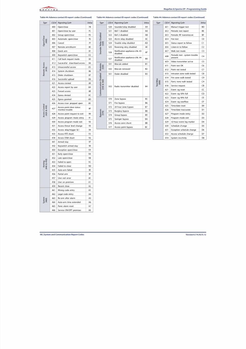
8/10/2019 Mgsp Ep27 Web
http://slidepdf.com/reader/full/mgsp-ep27-web 48/72
Version 4.7/4.92/5.1248 | System and Communication Report Codes
Magellan & Spectra SP • Programming Guide
O p e n
/ C l o s e
( 4 0 0 )
400 Open/close 7B
401 Open/close by user 7C
402 Group open/close 7D
403 Automatic open/close 7E
406 Cancel 7F
407 Remote arm/disarm 80408 Quick arm 81
409 Keyswitch open/close 82
R e m o t e
A c c e s s
( 4 1 0 )
411 Call back request made 83
412 Successful - download access 84
413 Unsuccessful access 85
414 System shutdown 86
415 Dialer shutdown 87
416 Successful upload 88
A c c e s s
C o n t r o
l
( 4 2 0 & 4 3 0 )
421 Access denied 89
422 Access report by user 8A
423 Forced access 8B
424 Egress denied 8C
425 Egress granted 8D
426 Access door propped open 8E
427 Access point door statusmonitor trouble 8F
428 Access point request to exit 90
429 Access program mode entry 91
430 Access program mode exit 92
431 Access threat level change 93
432 Access relay/trigger fail 94
433 Access RTE shunt 95
434 Access DSM shunt 96
A r m
i n g
( 4 4 0 & 4 5 0 )
441 Armed stay 97
442 Keyswitch armed stay 98
450 Exception open/close 99
451 Early open/close 9A
452 Late open/close 9B
453 Failed to open 9C
454 Failed to close 9D
455 Auto-arm failed 9E
456 Partial arm 9F
457 User exit error A0
458 User on premises A1
459 Recent close A2
S y s t e m
( 4 6 0 )
461 Wrong code entry A3
462 Legal code entry A4
463 Re-arm after alarm A5
464 Auto-arm time extended A6
465 Panic alarm reset A7
466 Service ON/OFF premises A8
Table 44: Ademco contact ID report codes (Continued)
Type CID # Reporting Code Value
S o u n
d e r
R e l a y
D i s a b l e d
( 5 2 0 )
520 Sounder/relay disabled A9
521 Bell 1 disabled AA
522 Bell 2 disabled AB
523 Alarm relay disabled AC
524 Trouble relay disabled AD
525 Reversing relay disabled AE
526 Notification appliance chk. #3disabled AF
527 Notification appliance chk. #4disabled B0
M o
d u
l e s
( 5 3 0 ) 531 Module added B1
532 Module removed B2
C o m m u n
i c a t i o n
D i s a b l e d
( 5 5 0 & 5 6 0 )
551 Dialer disabled B3
552 Radio transmitter disabled B4
B y p a s s e s
( 5 7 0 )
570 Zone bypass B5
571 Fire bypass B6
572 24-hour zone bypass B7
573 Burglary bypass B8
574 Group bypass B9
575 Swinger bypass BA
576 Access zone shunt BB
577 Access point bypass BC
Table 44: Ademco contact ID report codes (Continued)
Type CID # Reporting Code Value
T e s t / M i s c
( 6 0 0 )
601 Manual trigger test BD
602 Periodic test report BE
603 Periodic RF transmission BF
604 Fire test C0
605 Status report to follow C1
606 Listen-in to follow C2607 Walk test mode C3
608 Periodic test - system troublepresent C4
609 Video transmitter active C5
611 Point test OK C6
612 Point not tested C7
613 Intrusion zone walk tested C8
614 Fire zone walk tested C9
615 Panic zone walk tested CA
616 Service request CB
621 Event log reset CC
622 Event log 50% full CD623 Event log 90% full CE
624 Event log overflow CF
625 Time/date reset D0
626 Time/date inaccurate D1
627 Program mode entry D2
628 Program mode exit D3
629 32-hour event log marker D4
630 Schedule change D5
631 Exception schedule change D6
632 Access schedule change D7
654 System inactivity D8
Table 44: Ademco contact ID report codes (Continued)
Type CID # Reporting Code Value
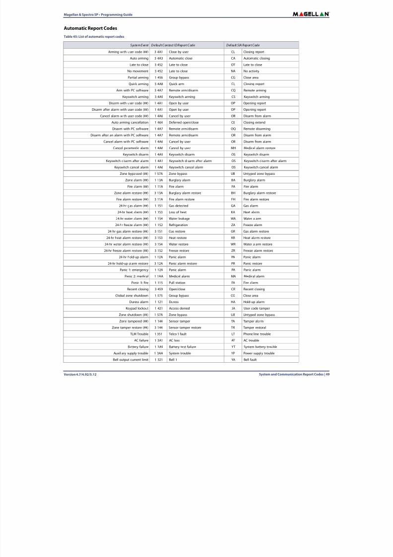
8/10/2019 Mgsp Ep27 Web
http://slidepdf.com/reader/full/mgsp-ep27-web 49/72
Magellan & Spectra SP • Programming Guide
Version 4.7/4.92/5.12 System and Communication Report Codes | 49
Automatic Report CodesTable 45: List of automatic report codes
System Event Default Contact ID Report Code Default SIA Report Code
Arming with user code (##) 3 4A1 Close by user CL Closing report
Auto arming 3 4A3 Automatic close CA Automatic closing
Late to close 3 452 Late to close OT Late to close
No movement 3 452 Late to close NA No activity
Partial arming 1 456 Group bypass CG Close area
Quick arming 3 4A8 Quick arm CL Closing report
Arm with PC software 3 4A7 Remote arm/disarm CQ Remote arming
Keyswitch arming 3 4A9 Keyswitch arming CS Keyswitch arming
Disarm with user code (##) 1 4A1 Open by user OP Opening report
Disarm after alarm with user code (##) 1 4A1 Open by user OP Opening report
Cancel alarm with user code (##) 1 4A6 Cancel by user OR Disarm from alarm
Auto arming cancellation 1 464 Deferred open/close CE Closing extend
Disarm with PC software 1 4A7 Remote arm/disarm OQ Remote disarming
Disarm after an alarm with PC software 1 4A7 Remote arm/disarm OR Disarm from alarm
Cancel alarm with PC software 1 4A6 Cancel by user OR Disarm from alarm
Cancel paramedic alarm 1 4A6 Cancel by user MH Medical alarm restore
Keyswitch disarm 1 4A9 Keyswitch disarm OS Keyswitch disarm
Keyswitch disarm after alarm 1 4A1 Keyswitch disarm after alarm OS Keyswitch disarm after alarm
Keyswitch cancel alarm 1 4A6 Keyswitch cancel alarm OS Keyswitch cancel alarm
Zone bypassed (##) 1 57A Zone bypass UB Untyped zone bypass
Zone alarm (##) 1 13A Burglary alarm BA Burglary alarm
Fire alarm (##) 1 11A Fire alarm FA Fire alarm
Zone alarm restore (##) 3 13A Burglary alarm restore BH Burglary alarm restore
Fire alarm restore (##) 3 11A Fire alarm restore FH Fire alarm restore
24-hr gas alarm (##) 1 151 Gas detected GA Gas alarm
24-hr heat alarm (##) 1 153 Loss of heat KA Heat alarm
24-hr water alarm (##) 1 154 Water leakage WA Water alarm
24-hr freeze alarm (##) 1 152 Refrigeration ZA Freeze alarm24-hr gas alarm restore (##) 3 151 Gas restore GR Gas alarm restore
24-hr heat alarm restore (##) 3 153 Heat restore KR Heat alarm restore
24-hr water alarm restore (##) 3 154 Water restore WR Water alarm restore
24-hr freeze alarm restore (##) 3 152 Freeze restore ZR Freeze alarm restore
24-hr hold-up alarm 1 12A Panic alarm PA Panic alarm
24-hr hold-up alarm restore 3 12A Panic alarm restore PR Panic restore
Panic 1: emergency 1 12A Panic alarm PA Panic alarm
Panic 2: medical 1 1AA Medical alarm MA Medical alarm
Panic 3: fire 1 115 Pull station FA Fire alarm
Recent closing 3 459 Open/close CR Recent closing
Global zone shutdown 1 575 Group bypass CG Close area
Duress alarm 1 121 Duress HA Hold-up alarm
Keypad lockout 1 421 Access denied JA User code tamper
Zone shutdown (##) 1 57A Zone bypass UB Untyped zone bypass
Zone tampered (##) 1 144 Sensor tamper TA Tamper alarm
Zone tamper restore (##) 3 144 Sensor tamper restore TR Tamper restoral
TLM Trouble 1 351 Telco 1 fault LT Phone line trouble
AC failure 1 3A1 AC loss AT AC trouble
Battery failure 1 3A9 Battery test failure YT System battery trouble
Auxiliary supply trouble 1 3AA System trouble YP Power supply trouble
Bell output current limit 1 321 Bell 1 YA Bell fault
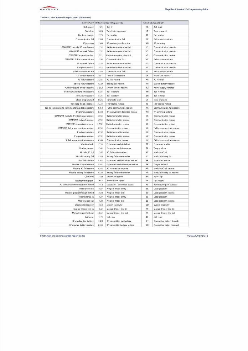
8/10/2019 Mgsp Ep27 Web
http://slidepdf.com/reader/full/mgsp-ep27-web 50/72
Version 4.7/4.92/5.1250 | System and Communication Report Codes
Magellan & Spectra SP • Programming Guide
Bell absent 1 321 Bell 1 YA Bell fault
Clock lost 1 626 Time/date inaccurate JT Time changed
Fire loop trouble 1 373 Fire trouble FT Fire trouble
Communication fail 1 354 Communication fail YC Fail to communicate
RF jamming 1 344 RF receiver jam detection XQ RF jamming
GSM/GPRS module RF interference 1 552 Radio transmitter disabled YS Communication troubleGSM/GPRS network failure 1 552 Radio transmitter disabled YS Communication trouble
GSM/GPRS supervision lost 1 552 Radio transmitter disabled YS Communication trouble
GSM/GPRS fail to communicate 1 354 Communication fails YC Fail to communicate
IP network failure 1 552 Radio transmitter disabled YS Communication trouble
IP supervision lost 1 552 Radio transmitter disabled YS Communication trouble
IP fail to communicate 1 354 Communication fails YC Fail to communicate
TLM trouble restore 3 351 Telco 1 fault restore LR Phone line restoral
AC failure restore 3 3A1 AC loss restore AR AC restoral
Battery failure restore 3 3A9 Battery test restore YR System battery restoral
Auxiliary supply trouble restore 3 3AA System trouble restore YQ Power supply restored
Bell output current limit restore 3 321 Bell 1 restore YH Bell restored
Bell absent restore 3 321 Bell 1 restore YH Bell restored
Clock programmed 3 625 Time/date reset JT Time changed
Fire loop trouble restore 3 373 Fire trouble restore FJ Fire trouble restore
Fail to communicate with monitoring station restore 3 354 Fail to communicate restore YK Communication fai ls restore
RF jamming restore 3 344 RF receiver jam detection restore XH RF jamming restoral
GSM/GPRS module RF interference restore 3 552 Radio transmitter restore YK Communication restore
GSM/GPRS network restore 3 552 Radio transmitter restore YK Communication restore
GSM/GPRS supervision restore 3 552 Radio transmitter restore YK Communication restore
GSM/GPRS fail to communicate restore 3 354 Communication restore YK Fail to communicate restore
IP network restore 3 552 Radio transmitter restore YK Communication restore
IP supervision restore 3 552 Radio transmitter restore YK Communication restore
IP fail to communicate restore 3 354 Communication restore YK Fail to communicate restore
Combus fault 1 333 Expansion module failure ET Expansion trouble
Module tamper 1 341 Expansion module tamper TA Tamper alarm
Module AC fail 1 342 AC failure on module AT Module AC fail
Module battery fail 1 338 Battery failure on module YT Module battery fail
Bus fault restore 3 333 Expansion module failure restore ER Expansion restoral
Module tamper restore 3 341 Expansion module tamper restore TR Tamper restoral
Module AC fail restore 3 342 AC restored on module AR Module AC fail restore
Module battery fail restore 3 338 Battery failure on module YR Module battery fail restore
Cold start 1 3A8 System shutdown RR Power up
Test report engaged 1 6A2 Periodic test report TX Test report
PC software communication finished 1 412 Successful - download access RS Remote program success
Installer on site 1 627 Program mode entry LB Local program
Installer programming finished 1 628 Program mode exit LS Local program success
Maintenance in 1 627 Program mode entry LB Local program
Maintenance out 1 628 Program mode exit LS Local program success
Closing delinquency 1 654 System inactivity CD System inactivity
Manual trigger test in 1 6A1 Manual trigger test in TS Manual trigger test in
Manual trigger test out 3 6A1 Manual trigger test out TS Manual trigger test out
Exit error 1 374 Exit error EE Exit error
RF module low battery 1 384 RF transmitter low battery XT Transmitter battery trouble
RF module battery restore 3 384 RF transmitter battery restore XR Transmitter batter y restoral
Table 45: List of automatic report codes (Continued)
System Event Default Contact ID Report Code Default SIA Report Code
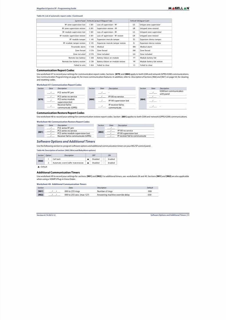
8/10/2019 Mgsp Ep27 Web
http://slidepdf.com/reader/full/mgsp-ep27-web 51/72
Magellan & Spectra SP • Programming Guide
Version 4.7/4.92/5.12 Software Options and Additional Timers | 51
Communication Report CodesUse worksheet 47 to record your settings for communication report codes. Sections [879] and [884] apply to both GSM and network (GPRS/GSM) communications.See Communication Programming on page 42 , for more communication features. In addition, refer to Description of Sections [966] and [967] on page 54 , for clearingand resetting codes.
Communication Restore Report CodesUse worksheet 48 to record your settings for communication restore report codes. Section [881] applies to both GSM and network (GPRS/GSM) communications.
Software Options and Additional TimersUse the following section to program software options and additional communication timers on your MG/SP control panel.
Additional Communication TimersUse worksheet 49 to record your settings for sections [901] and [902] . For additional timers, see worksheets 38 and 40. Sections [901] and [902] are also applicablewhen using a VDMP3 Plug-in Voice Dialer.
RF zone supervision lost 1 381 Loss of supervision - RF US Untype zone supervision
RF zone supervision restore 3 381 Supervision restore - RF UR Untyped zone restoral
RF module supervision lost 1 381 Loss of supervision - RF US Untyped zone supervision
RF module supervision restore 3 381 Loss of supervision - RF restore UR Untyped zone restoral
RF module tamper 1 145 Expansion module tamper ES Expansion device tamper
RF module t amper restore 3 145 Expansion module tamper restore EJ Expansion device restoreParamedic alarm 1 1AA Medical MA Medical alarm
Zone forced 1 57A Zone forced XW Zone forced
Zone included 3 57A Zone included UU Zone included
Remote low battery 1 338 Battery failure on module YT Module battery fail
Remote low battery restore 3 338 Battery failure on module restore YR Module battery fail restore
Failed to arm 1 454 Failed to close CI Failed to close
Worksheet 47: Communication Report CodesSection Data Description Section Data Description Section Data Description
[879]
___/___ PCS series RF jam
[880]
___/___ -
[884]
___/___GSM lost communicationwith panel
___/___ PCS series no service ___/___ IP100 no service ___/___ -
___/___PCS series modulesupervision lost
___/___ IP100 supervision lost ___/___ -
___/___Receiver fail tocommunicate (GPRS)
___/___IP receiver fail tocommunicate
___/___ -
Worksheet 48: Communication Restore Report CodesSection Data Description Section Data Description
[881]
___/___ PCS series RF jam
[882]
___/___ -___/___ PCS series no service ___/___ IP100 no service___/___ PCS series module supervision lost ___/___ IP100 supervision lost___/___ Receiver fail to communicate (GPRS) ___/___ IP receiver fail to communicate
Table 46: Description of section [900] (WinLoad/BabyWare options)
Section Option Description OFF ON
[900]1 Call back Disabled Enabled
2 Automatic event buffer transmission Disabled Enabled
= Default
Worksheet 49: Additional Communication TimersSection Data Description Default
[901] ___/___/___ 000 to 255 rings Number of rings 008
[902] ___/___/___ 000 to 255 secs. (max 127) Answering machine override delay 030
Table 45: List of automatic report codes (Continued)
System Event Default Contact ID Report Code Default SIA Report Code
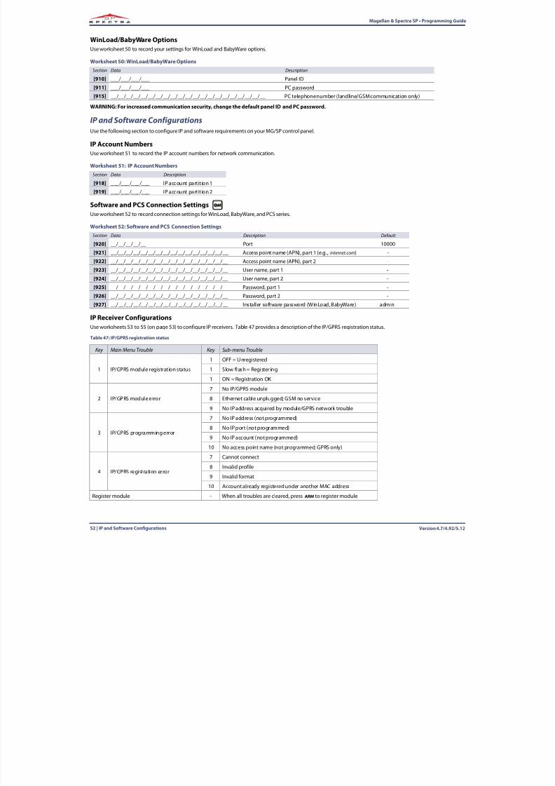
8/10/2019 Mgsp Ep27 Web
http://slidepdf.com/reader/full/mgsp-ep27-web 52/72
Version 4.7/4.92/5.1252 | IP and Software Configurations
Magellan & Spectra SP • Programming Guide
WinLoad/BabyWare OptionsUse worksheet 50 to record your settings for WinLoad and BabyWare options.
WARNING: For increased communication security, change the default panel ID and PC password.
IP and Software ConfigurationsUse the following section to configure IP and software requirements on your MG/SP control panel.
IP Account NumbersUse worksheet 51 to record the IP account numbers for network communication.
Software and PCS Connection SettingsUse worksheet 52 to record connection settings for WinLoad, BabyWare, and PCS series.
IP Receiver ConfigurationsUse worksheets 53 to 55 (on page 53 ) to configure IP receivers. Table 47 provides a description of the IP/GPRS registration status.
Worksheet 50: WinLoad/BabyWare OptionsSection Data Description
[910] ___/___/___/___ Panel ID
[911] ___/___/___/___ PC password
[915] __/__/__/__/__/__/__/__/__/__/__/__/__/__/__/__/__/__/__/__/__ PC telephone number (landline/GSM communication only)
Worksheet 51: IP Account NumbersSection Data Description
[918] ___/___/___/___ IP account partition 1
[919] ___/___/___/___ IP account partition 2
Worksheet 52: Software and PCS Connection SettingsSection Data Description Default
[920] __/__/__/__/__ Port 10000
[921] __/__/__/__/__/__/__/__/__/__/__/__/__/__/__/__ Access point name (APN), part 1 (e.g., internet.com ) -
[922] __/__/__/__/__/__/__/__/__/__/__/__/__/__/__/__ Access point name (APN), part 2 -
[923] __/__/__/__/__/__/__/__/__/__/__/__/__/__/__/__ User name, part 1 -
[924] __/__/__/__/__/__/__/__/__/__/__/__/__/__/__/__ User name, part 2 -
[925] __/__/__/__/__/__/__/__/__/__/__/__/__/__/__/__ Password, part 1 -
[926] __/__/__/__/__/__/__/__/__/__/__/__/__/__/__/__ Password, part 2 -
[927] __/__/__/__/__/__/__/__/__/__/__/__/__/__/__/__ Installer software password (WinLoad, BabyWare) admin
Table 47: IP/GPRS registration status
Key Main Menu Trouble Key Sub-menu Trouble
1 IP/GPRS module registration status
1 OFF = Unregistered
1 Slow flash = Registering
1 ON = Registration OK
2 IP/GPRS module error
7 No IP/GPRS module
8 Ethernet cable unplugged; GSM no service
9 No IP address acquired by module/GPRS network trouble
3 IP/GPRS programming error
7 No IP address (not programmed)
8 No IP port (not programmed)
9 No IP account (not programmed)
10 No access point name (not programmed; GPRS only)
4 IP/GPRS registration error
7 Cannot connect
8 Invalid profile
9 Invalid format
10 Account already registered under another MAC address
Register module - When all troubles are cleared, press ARM to register module
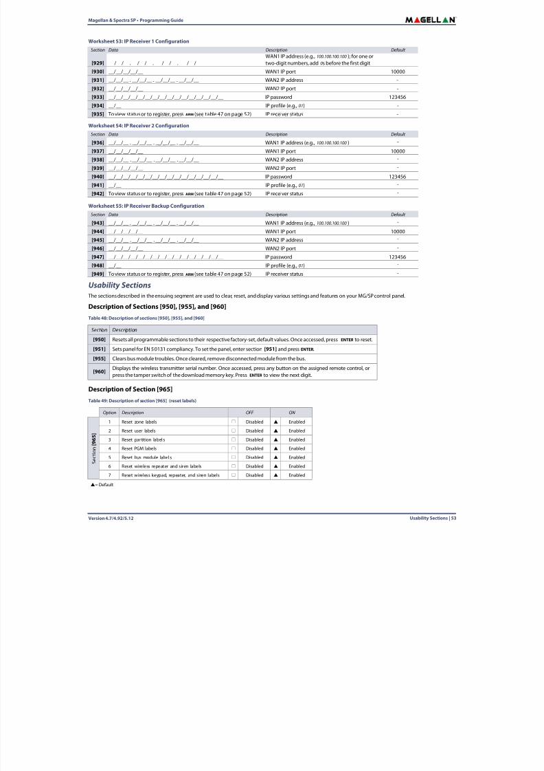
8/10/2019 Mgsp Ep27 Web
http://slidepdf.com/reader/full/mgsp-ep27-web 53/72
Magellan & Spectra SP • Programming Guide
Version 4.7/4.92/5.12 Usability Sections | 53
Usability Sections The sections described in the ensuing segment are used to clear, reset, and display various settings and features on your MG/SP control panel.
Description of Sections [950], [955], and [960]
Description of Section [965]
Worksheet 53: IP Receiver 1 ConfigurationSection Data Description Default
[929] __/__/__ . __/__/__. __/__/__. __/__/__WAN1 IP address (e.g., 100.100.100.100 ); for one ortwo-digit numbers, add 0s before the first digit
-
[930] __/__/__/__/__ WAN1 IP port 10000
[931] __/__/__ . __/__/__ . __/__/__ . __/__/__ WAN2 IP address -
[932] __/__/__/__/__ WAN2 IP port -
[933] __/__/__/__/__/__/__/__/__/__/__/__/__/__/__/__ IP password 123456
[934] __/__ IP profile (e.g., 01) -[935] To view status or to register, press ARM (see table 47 on page 52 ) IP receiver status -
Worksheet 54: IP Receiver 2 ConfigurationSection Data Description Default
[936] __/__/__ . __/__/__ . __/__/__ . __/__/__ WAN1 IP address (e.g., 100.100.100.100 ) -
[937] __/__/__/__/__ WAN1 IP port 10000
[938] __/__/__ . __/__/__ . __/__/__ . __/__/__ WAN2 IP address -
[939] __/__/__/__/__ WAN2 IP port -
[940] __/__/__/__/__/__/__/__/__/__/__/__/__/__/__/__ IP password 123456
[941] __/__ IP profile (e.g., 01) -
[942] To view status or to register, press ARM (see table 47 on page 52 ) IP receiver status -
Worksheet 55: IP Receiver Backup ConfigurationSection Data Description Default
[943] __/__/__ . __/__/__ . __/__/__ . __/__/__ WAN1 IP address (e.g., 100.100.100.100 ) -
[944] __/__/__/__/__ WAN1 IP port 10000
[945] __/__/__ . __/__/__ . __/__/__ . __/__/__ WAN2 IP address -
[946] __/__/__/__/__ WAN2 IP port -
[947] __/__/__/__/__/__/__/__/__/__/__/__/__/__/__/__ IP password 123456
[948] __/__ IP profile (e.g., 01) -
[949] To view status or to register, press ARM (see table 47 on page 52 ) IP receiver status -
Table 48: Description of sections [950], [955], and [960]
Section Description
[950] Resets all programmable sections to their respective factory-set, default values. Once accessed, press ENTER to reset.
[951] Sets panel for EN 50131 compliancy. To set the panel, enter section [951] and press ENTER.
[955] Clears bus module troubles. Once cleared, remove disconnected module from the bus.
[960] Displays the wireless transmitter serial number. Once accessed, press any button on the assigned remote control, orpress the tamper switch of the download memory key. Press ENTER to view the next digit.
Table 49: Description of section [965] (reset labels)
Option Description OFF ON
S e c t i o n
[ 9 6 5 ]
1 Reset zone labels Disabled Enabled
2 Reset user labels Disabled Enabled
3 Reset par tition label s Disabled Enabled
4 Reset PGM labels Disabled Enabled
5 Reset bus module label s Disabled Enabled
6 Reset wireless repeater and siren labels Disabled Enabled
7 Reset wireless keypad, repeater, and siren labels Disabled Enabled
= Default
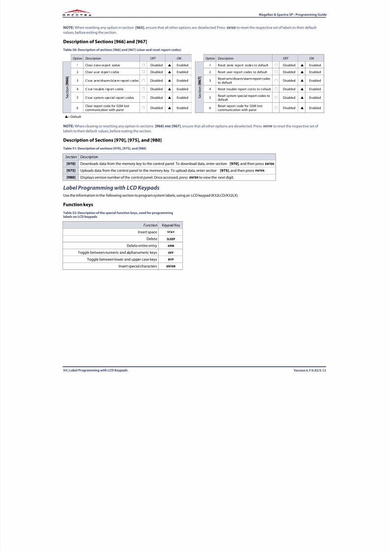
8/10/2019 Mgsp Ep27 Web
http://slidepdf.com/reader/full/mgsp-ep27-web 54/72
Version 4.7/4.92/5.1254 | Label Programming with LCD Keypads
Magellan & Spectra SP • Programming Guide
NOTE:When resetting any option in section [965] , ensure that all other options are deselected. Press ENTER to reset the respective set of labels to their defaultvalues, before exiting the section.
Description of Sections [966] and [967]
NOTE:When clearing or resetting any option in sections [966] AND [967] , ensure that all other options are deselected. Press ENTER to reset the respective set oflabels to their default values, before exiting the section.
Description of Sections [970], [975], and [980]
Label Programming with LCD KeypadsUse the information in the following section to program system labels, using an LCD keypad (K32LCD/K32LX).
Function keys
Table 50: Description of sections [966] and [967] (clear and reset report codes)
Option Description OFF ON Option Description OFF ON
S e c t i o n
[ 9 6 6 ]
1 Clear zone report codes Disabled Enabled
S e c t i o n
[ 9 6 7 ]
1 Reset zone report codes to default Disabled Enabled
2 Clear user repor t codes Disabled Enabled 2 Reset user report codes to default Disabled Enabled
3 Clear arm/disarm/alarm report codes Disabled Enabled 3 Reset arm/disarm/alarm report codesto default
Disabled Enabled
4 Clear trouble report codes Disabled Enabled 4 Reset trouble report codes to default Disabled Enabled
5 Clear system special report codes Disabled Enabled 5 Reset system special report codes todefault
Disabled Enabled
6 Clear report code for GSM lostcommunication with panel
Disabled Enabled 6 Reset report code for GSM lostcommunication with panel
Disabled Enabled
= Default
Table 51: Description of sections [970], [975], and [980]
Section Description
[970] Downloads data from the memory key to the control panel. To download data, enter section [970] , and then press ENTER.
[975] Uploads data from the control panel to the memory key. To upload data, enter section [975] , and then press ENTER.
[980] Displays version number of the control panel. Once accessed, press ENTER to view the next digit.
Table 52: Description of the special function keys, used for programminglabels on LCD keypads
Function Keypad Key
Insert space STAY
Delete SLEEP
Delete entire entry ARM
Toggle between numeric and alphanumeric keys OFF
Toggle between lower and upper case keys BYP
Insert special characters ENTER
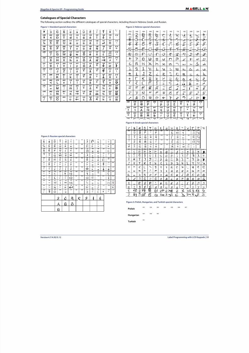
8/10/2019 Mgsp Ep27 Web
http://slidepdf.com/reader/full/mgsp-ep27-web 55/72
Magellan & Spectra SP • Programming Guide
Version 4.7/4.92/5.12 Label Programming with LCD Keypads | 55
Catalogues of Special Characters The following section outlines the different catalogues of special characters, including those in Hebrew, Greek, and Russian.
Figure 2: Hebrew special characters
032 048 064 080 096 112 160 176 192 208 224 240
033 049 065 081 097 113 161 177 193 209 225 241
034 050 066 082 098 114 162 178 194 210 226 242
035 051 067 083 099 115 163 179 195 211 227 243
036 052 068 084 100 116 164 180 196 212 228 244
037 053 069 085 101 117 165 181 197 213 229 245
038 054 070 086 102 118 166 182 198 214 230 246
039 055 071 087 103 119 167 183 199 215 231 247
040 056 072 088 104 120 168 184 200 216 232 248
041 057 073 089 105 121 169 185 201 217 233 249
042 058 074 090 106 122 170 186 202 218 234 250
043 059 075 091 107 123 171 187 203 219 235 251
044 060 076 092 108 124 172 188 204 220 236 252
045 061 077 093 109 125 173 189 205 221 237 253
046 062 078 094 110 126 174 190 206 222 238 254
047 063 079 095 111 127 175 191 207 223 239 255
Figure 1: Standard special characters
Figure 3: Russian special characters
Figure 4: Greek special characters
016 032 048 064 080 096 112 128 144 160 176 192 208 224 240
017 033 049 065 081 097 113 129 145 161 177 193 209 225 241
018 034 050 066 082 098 114 130 146 162 178 194 210 226 242
019 035 051 067 083 099 115 131 147 163 179 195 211 227 243
020 036 052 068 084 100 116 132 148 164 180 196 212 228 244
021 037 053 A069 085 101 117 133 149 165 181 197 213 229 245
022 038 054 070 086 102 118 134 150 166 182 198 214 230 246
023 039 055 071 087 103 119 135 151 167 183 199 215 231 247
024 040 056 072 088 104 120 136 152 168 184 200 216 232 248
025 041 057 073 089 105 121 137 153 169 185 201 217 233 249
026 042 058 074 090 106 122 138 154 170 186 202 218 234 250
027 043 059 075 091 107 123 139 155 171 187 203 219 235 251
028 044 060 076 092 108 124 140 156 172 188 204 220 236 252
029 045 061 077 093 109 125 141 157 173 189 205 221 237 253
030 046 062 078 094 110 126 142 158 174 190 206 222 238 254
031 047 063 079 095 111 127 143 159 175 191 207 223 239 255
Figure 5: Polish, Hungarian, and Turkish special characters
Polish001 002 003 004 005 006 007
Hungarian001 002 003
Turkish001
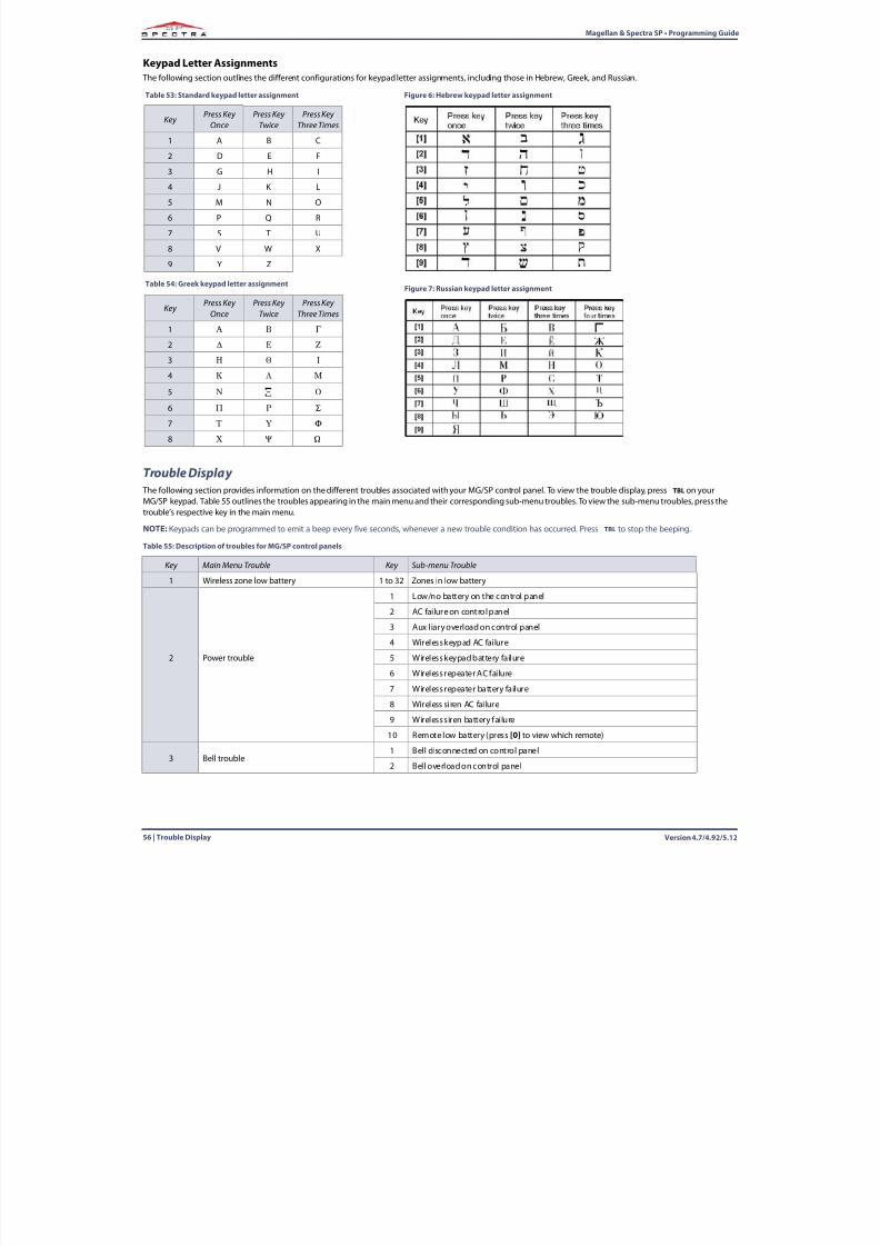
8/10/2019 Mgsp Ep27 Web
http://slidepdf.com/reader/full/mgsp-ep27-web 56/72
Version 4.7/4.92/5.1256 | Trouble Display
Magellan & Spectra SP • Programming Guide
Keypad Letter Assignments The following section outlines the different configurations for keypad letter assignments, including those in Hebrew, Greek, and Russian.
Trouble Display The following section provides information on the different troubles associated with your MG/SP control panel. To view the trouble display, press TBL on your
MG/SP keypad. Table 55 outlines the troubles appearing in the main menu and their corresponding sub-menu troubles. To view the sub-menu troubles, press thetrouble’s respective key in the main menu.
NOTE:Keypads can be programmed to emit a beep every five seconds, whenever a new trouble condition has occurred. Press TBL to stop the beeping.
Table 55: Description of troubles for MG/SP control panels
Key Main Menu Trouble Key Sub-menu Trouble
1 Wireless zone low battery 1 to 32 Zones in low battery
2 Power trouble
1 Low/no battery on the control panel
2 AC failure on control panel
3 Auxiliary overload on control panel
4 Wireless keypad AC failure
5 Wireless keypad battery failure
6 Wireless repeater AC failure7 Wireless repeater battery failure
8 Wireless siren AC failure
9 Wireless siren battery failure
10 Remote low battery (press [0] to view which remote)
3 Bell trouble1 Bell disconnected on control panel
2 Bell overload on control panel
Table 53: Standard keypad letter assignment
Key Press Key
OncePress Key
TwicePress Key
Three Times
1 A B C
2 D E F
3 G H I
4 J K L
5 M N O
6 P Q R
7 S T U
8 V W X
9 Y Z
Table 54: Greek keypad letter assignment
Key Press Key
OncePress Key
TwicePress Key
Three Times
1
2
3
4
5
6
7
8
Figure 6: Hebrew keypad letter assignment
Figure 7: Russian keypad letter assignment
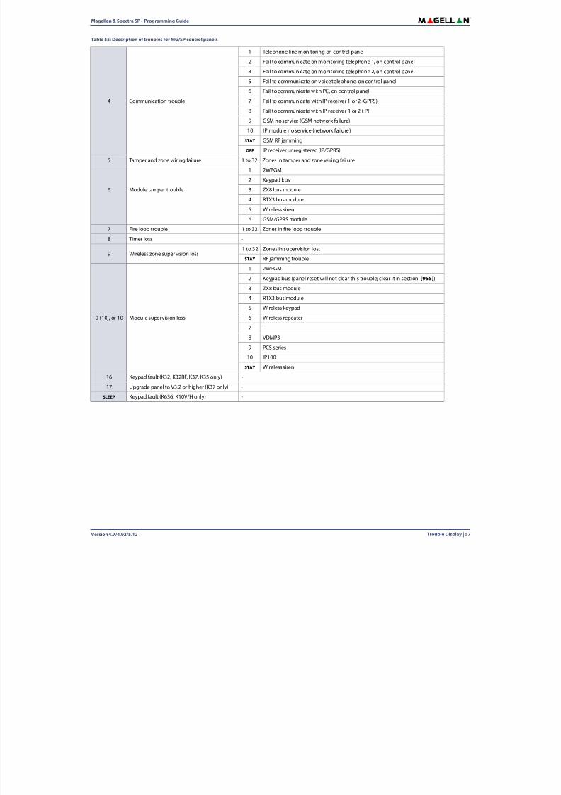
8/10/2019 Mgsp Ep27 Web
http://slidepdf.com/reader/full/mgsp-ep27-web 57/72
Magellan & Spectra SP • Programming Guide
Version 4.7/4.92/5.12 Trouble Display | 57
4 Communication trouble
1 Telephone line monitoring on control panel
2 Fail to communicate on monitoring telephone 1, on control panel
3 Fail to communicate on monitoring telephone 2, on control panel
5 Fail to communicate on voice telephone, on control panel
6 Fail to communicate with PC, on control panel
7 Fail to communicate with IP receiver 1 or 2 (GPRS)
8 Fail to communicate with IP receiver 1 or 2 (IP)
9 GSM no service (GSM network failure)
10 IP module no service (network failure)
STAY GSM RF jamming
OFF IP receiver unregistered (IP/GPRS)
5 Tamper and zone wiring failure 1 to 32 Zones in tamper and zone wiring failure
6 Module tamper trouble
1 2WPGM
2 Keypad bus
3 ZX8 bus module
4 RTX3 bus module
5 Wireless siren
6 GSM/GPRS module
7 Fire loop trouble 1 to 32 Zones in fire loop trouble
8 Timer loss -
9 Wireless zone supervision loss1 to 32 Zones in supervision lost
STAY RF jamming trouble
0 (10), or 10 Module supervision loss
1 2WPGM
2 Keypad bus (panel reset will not clear this trouble; clear it in section [955] )
3 ZX8 bus module
4 RTX3 bus module
5 Wireless keypad
6 Wireless repeater
7 -
8 VDMP3
9 PCS series
10 IP100
STAY Wireless siren
16 Keypad fault (K32, K32RF, K37, K35 only) -
17 Upgrade panel to V3.2 or higher (K37 only) -
SLEEP Keypad fault (K636, K10V/H only) -
Table 55: Description of troubles for MG/SP control panels
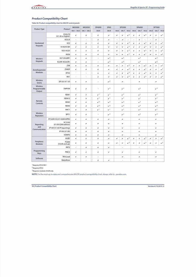
8/10/2019 Mgsp Ep27 Web
http://slidepdf.com/reader/full/mgsp-ep27-web 58/72
Version 4.7/4.92/5.1258 | Product Compatibility Chart
Magellan & Spectra SP • Programming Guide
Product Compatibility Chart
1 Requires RTX3/RX12 Requires RTX33 Requires modules V5.00 only
NOTE:For the most up-to-date and comprehensive MG/SP product compatibility chart, always refer to paradox.com.
Table 56: Product compatibility chart for MG/SP control panels
Product Type Product MG5000 MG5050 SP4000 SP65 SP5500 SP6000 SP7000
V4.1 - V4.5 V4.1 - V4.5 V4.9 V4.9 V4.5 V4.7 V5.0 V4.5 V4.7 V5.0 V4.5 V4.7 V
HardwiredKeypads
K32LCD(V1.30 or higher)
3 3 3
K32LX - - - - - - - -
K32 3 3 3
K10V/K10H 3 3 3
K35 (K32I) 3 3 3
K636 3 3 3
WirelessKeypads
K37 (K32IRF) - 2 2 2 2
K32RF (K32LRF) - 2 2 2 2
Zone ExpansionModules
ZX8 3 3 3
ZX8SP 3 3 3
RTX3 - - 3 3 3
RX1 - - 3 3 3
WirelessSirens
SR150 (V1.10) - 2
WirelessProgrammable
Output2WPGM - 2 2 2 2
RemoteControls
REM1 1 1 1 1 1
REM15 1 1 1 1 1
REM2 2 2 2 2 2
REM3 2 2 2 2 2
RAC1 1 1 1 1 1
WirelessRepeaters
RPT1 - 2 2 2 2
Reportingand
Communication
PCS200 (V2.01 GSM/GPRS)
PCS200(V1.00 GSM edition)
IP100 (V1.50 IP reporting)
IP100 (V1.00)
VDMP3
PeripheralModules
HUB2 3 3 3
PGM4(V3.00 and up)
3 3 3
PRT3 - - - -
ProgrammingKeys
PMC5
SoftwareWinLoad -
BabyWare - - - - -
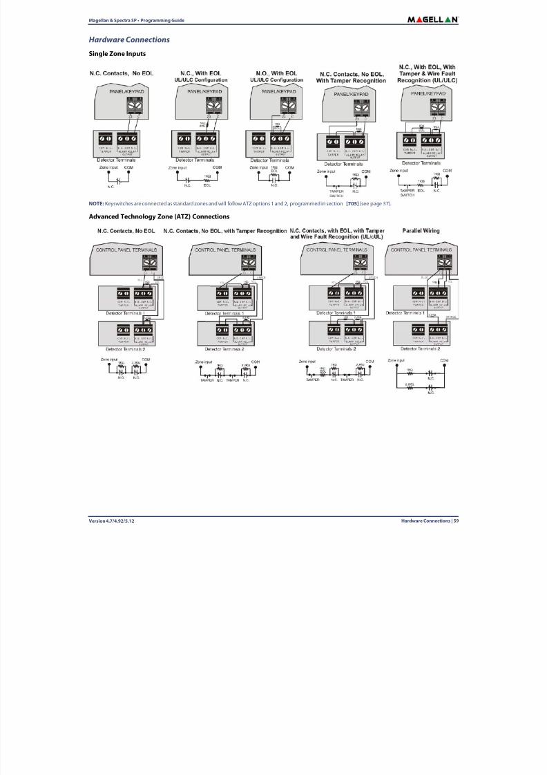
8/10/2019 Mgsp Ep27 Web
http://slidepdf.com/reader/full/mgsp-ep27-web 59/72
Magellan & Spectra SP • Programming Guide
Version 4.7/4.92/5.12 Hardware Connections | 59
Hardware Connections
Single Zone Inputs
NOTE:Keyswitches are connected as standard zones and will follow ATZ options 1 and 2, programmed in section [705] (see page 37 ).
Advanced Technology Zone (ATZ) Connections
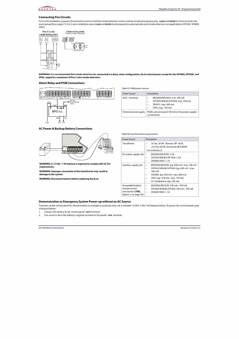
8/10/2019 Mgsp Ep27 Web
http://slidepdf.com/reader/full/mgsp-ep27-web 60/72
Version 4.7/4.92/5.1260 | Hardware Connections
Magellan & Spectra SP • Programming Guide
Connecting Fire CircuitsFor 4-wire installation, program the activation event so that the smoke detectors can be reset by simultaneously pressing CLEAR and ENTER for three seconds (seeevent group 06 on page 21 ). For 2-wire installation, press CLEAR and ENTER simultaneously to automatically reset smoke detectors (not applicable to SP5500, SP4000,SP65).
WARNING: It is recommended that smoke detectors be connected in a daisy-chain configuration. Each control panel, except for the SP4000, SP5500, andSP65, supports a maximum of five 2-wire smoke detectors.
Alarm Relay and PGM Connections
AC Power & Backup Battery Connections
Demonstration or Emergency System Power-up without an AC Source To power-up the control panel for demonstration or emergency purposes only, use a standard 12 VDC, 4 Ah/7 Ah backup battery. To power the control panel usinga backup battery:1. Connect the battery to the control panel's BATT terminal.2. Use a wire to short the battery's negative terminal to the panel's AUX- terminal.
Table 57: PGM power sources
Power Source Description
AUX + terminal • MG5000/MG5050: max. 700 mA• SP5500/SP6000/SP7000: max. 700 mA• SP4000: max. 600 mA• SP65: max. 750 mA
External power supply PGMs cannot exceed 100 mA or the power supply’scurrent limit.
Table 58: Transformation requirements
Power Source Description
Transformer • 16 Vac 20 VA* (Amseco XP-1620)• 16.5 Vac 40 VA (Universal UB1640W)* not verified by UL
DC power supply rate • MG5000/MG5050: 1.0A• SP5500/SP6000/SP7000: 1.4A• SP4000/SP65: 1.1A
Auxiliary supply rate • MG5000/MG5050: typ. 600 mA / max. 700 mA• SP5500/SP6000/SP7000: typ. 600 mA / max.
700 mA• SP4000: typ. 450 mA / max. 600 mA• SP65: typ. 500 mA / max. 750 mA• UL installations: typ. 200 mA
Acceptable batterycharge current(see section [700] ,option 2, on page 36 )
• MG5000/MG5050: 350 mA / 700 mA• SP5500/SP6000/SP7000: 350 mA / 700 mA• SP4000/SP65: 1.1A
WARNING: A 12 Vdc / 7 Ah battery is required to comply with UL firerequirements.
WARNING: Improper connection of the transformer may result indamage to the system.
WARNING: Disconnect battery before replacing the fuse.
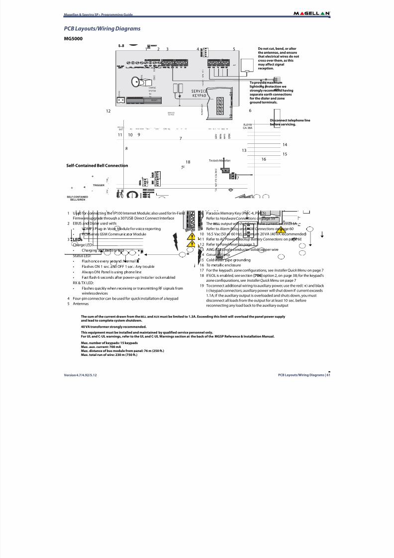
8/10/2019 Mgsp Ep27 Web
http://slidepdf.com/reader/full/mgsp-ep27-web 61/72
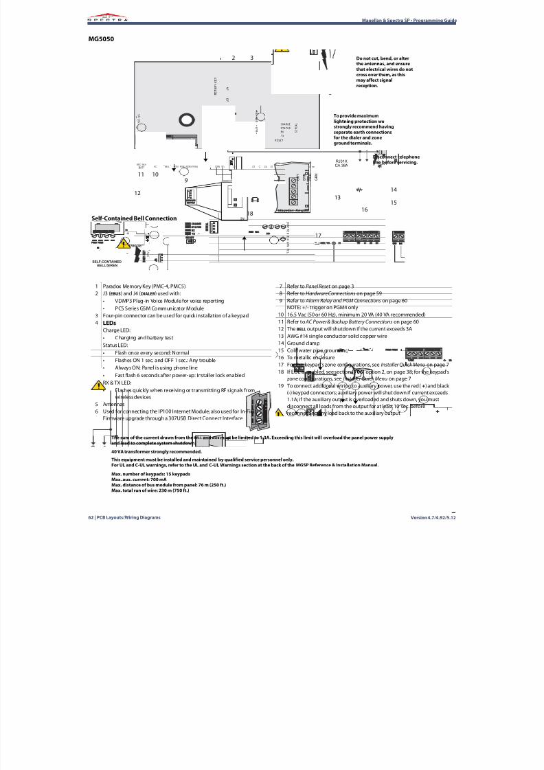
8/10/2019 Mgsp Ep27 Web
http://slidepdf.com/reader/full/mgsp-ep27-web 62/72
Version 4.7/4.92/5.1262 | PCB Layouts/Wiring Diagrams
Magellan & Spectra SP • Programming Guide
MG5050
RED BLK
5 A / 1 2 5 V
AC PGM1 PGM2 AUX Z2C+ -R -1 T-1 RING TIPGND
RESET
S E R I A L
M E M O R Y
K E Y
STATUS
BELL+ -
BATT GRN YEL Z1
J 3
RX
TX
CHARGE
PGM4PGM3 Z3 C Z4 Z5
J 4
R E D
B L K
G R N
Y E L
Z O N E
Magellan Keypad
B R N
G R Y
R E D
G R N
RJ31XCA 38A
1 K
E OL
- +
SERVICE
KEYPAD
SERVICE
KEYPAD
+
A U X
-
G R N
Y E L
A N T
ANT
To provide maximumlightning protection westrongly recommend havingseparate earth connectionsfor the dialer and zoneground terminals.
6
4 5
Disconnect telephoneline before servicing.
89
1314
1516
17
18Self-Contained Bell Connection
B E L L
+
-
A U X
+
-
TRIGGER
-
+
SELF-CONTAINEDBELL/SIREN
+ -
1
1011
Do not cut, bend, or alterthe antennas, and ensurethat electrical wires do notcross over them, as thismay affect signalreception.
2 3
7
12
19
1 Paradox Memory Key (PMC-4, PMC5)2 J3 (EBUS) and J4 ( DIALER) used with:
• VDMP3 Plug-in Voice Module for voice reporting• PCS Series GSM Communicator Module
3 Four-pin connector can be used for quick installation of a keypad4 LEDs
Charge LED:• Charging and battery testStatus LED:• Flash once every second: Normal• Flashes ON 1 sec. and OFF 1 sec.: Any trouble• Always ON: Panel is using phone line• Fast flash 6 seconds after power-up: Installer lock enabledRX & TX LED:• Flashes quickly when receiving or transmitting RF signals from
wireless devices5 Antennas6 Used for connecting the IP100 Internet Module; also used for In-Field
Firmware upgrade through a 307USB Direct Connect Interface
7 Refer to Panel Reset on page 38 Refer to Hardware Connections on page 599 Refer to Alarm Relay and PGM Connections on page 60
NOTE: +/- trigger on PGM4 only10 16.5 Vac (50 or 60 Hz), minimum 20 VA (40 VA recommended)11 Refer to AC Power & Backup Battery Connections on page 6012 The BELL output will shutdown if the current exceeds 3A13 AWG #14 single conductor solid copper wire14 Ground clamp15 Cold water pipe grounding16 To metallic enclosure17 For the keypad’s zone configurations, see Installer Quick Menu on page 718 If EOL is enabled, see section [706] option 2, on page 38 ; for the keypad’s
zone configurations, see Installer Quick Menu on page 719 To connect additional wiring to auxiliary power, use the red ( +) and black
(-) keypad connectors; auxiliary power will shut down if current exceeds1.1A; if the auxiliary output is overloaded and shuts down, you mustdisconnect all loads from the output for at least 10 sec. beforereconnecting any load back to the auxiliary output
40 VA transformer strongly recommended.
Max. number of keypads: 15 keypadsMax. aux. current: 700 mAMax. distance of bus module from panel: 76 m (250 ft.)Max. total run of wire: 230 m (750 ft.)
This equipment must be installed and maintained by qualified service personnel only.For UL and C-UL warnings, refer to the UL and C-UL Warnings section at the back of the MGSP Reference & Installation Manual.
The sum of the current drawn from the BELL and AUX must be limited to 1.3A. Exceeding this limit will overload the panel power supplyand lead to complete system shutdown.

8/10/2019 Mgsp Ep27 Web
http://slidepdf.com/reader/full/mgsp-ep27-web 63/72
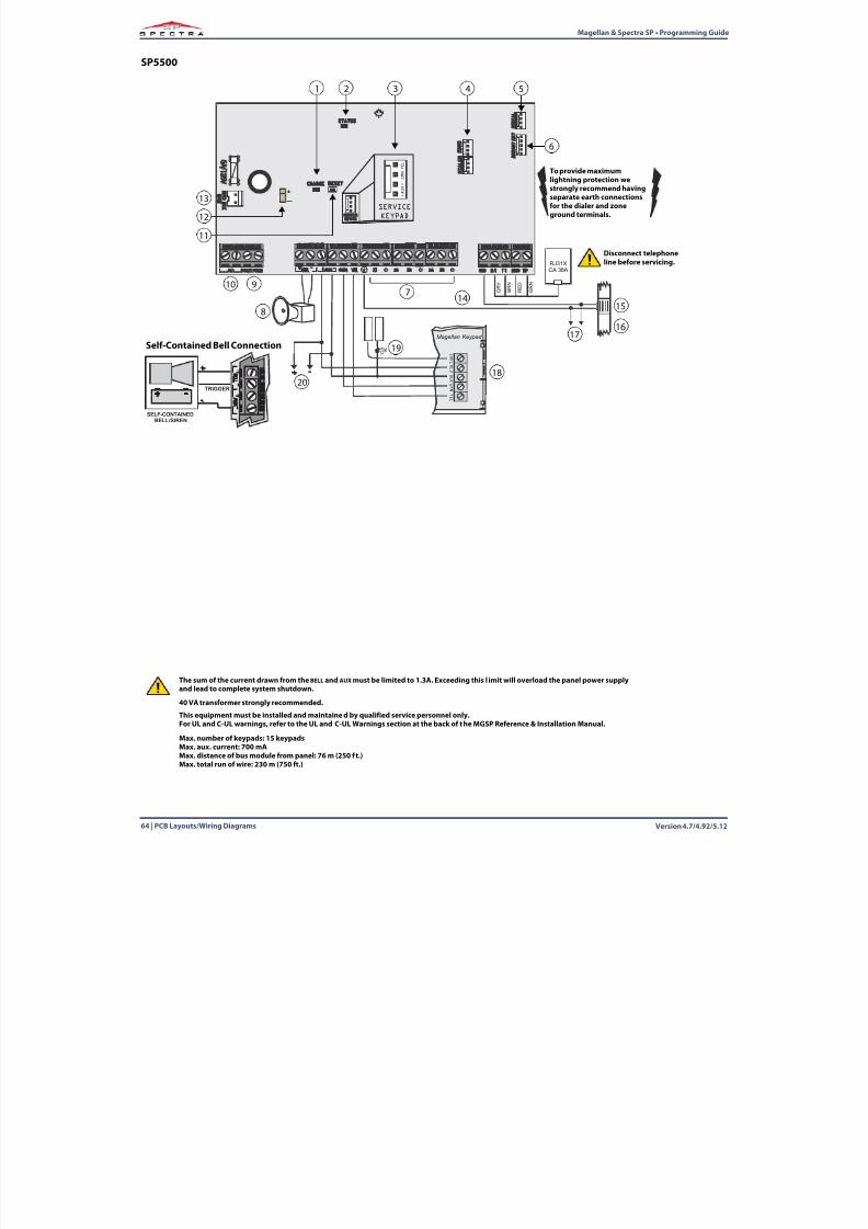
8/10/2019 Mgsp Ep27 Web
http://slidepdf.com/reader/full/mgsp-ep27-web 64/72
Version 4.7/4.92/5.1264 | PCB Layouts/Wiring Diagrams
Magellan & Spectra SP • Programming Guide
SP5500
R E D B L K
5 A / 1 2 5 V
R-1 T-1 RING TIPGND
RESET
S E R I A L
M E M O R Y
K E Y
STATUS
AC PGM1 PGM2
SERVICE
KEYPAD
SERVICE
KEYPAD
+ A U X
-
G R N
Y E
L
B R N
G R Y
R E D
G R N
RJ31XCA 38A
B A T T
D I A L E R
R E D
B L K
G R N
Y E L
Z O N E
Magellan Keypad
1 K
E OL
- +
CHARGE
E B U S
AUX Z2C+ -BELL+ -
GRN YEL Z1 Z3 C Z4 Z5 C
+_
B E L L
+
-
A U X
+
-
TRIGGER
-
+
SELF-CONTAINEDBELL/SIREN
+ -
To provide maximumlightning protection westrongly recommend havingseparate earth connectionsfor the dialer and zoneground terminals.
2
6
12
4 53
Disconnect telephoneline before servicing.
7
8
9
13
1415
1617
18
19
20
Self-Contained Bell Connection
1
10
11
40 VA transformer strongly recommended.
Max. number of keypads: 15 keypadsMax. aux. current: 700 mAMax. distance of bus module from panel: 76 m (250 f t.)Max. total run of wire: 230 m (750 ft.)
This equipment must be installed and maintained by qualified service personnel only.For UL and C-UL warnings, refer to the UL and C-UL Warnings section at the back of the MGSP Reference & Installation Manual.
The sum of the current drawn from the BELL and AUX must be limited to 1.3A. Exceeding this l imit will overload the panel power supplyand lead to complete system shutdown.
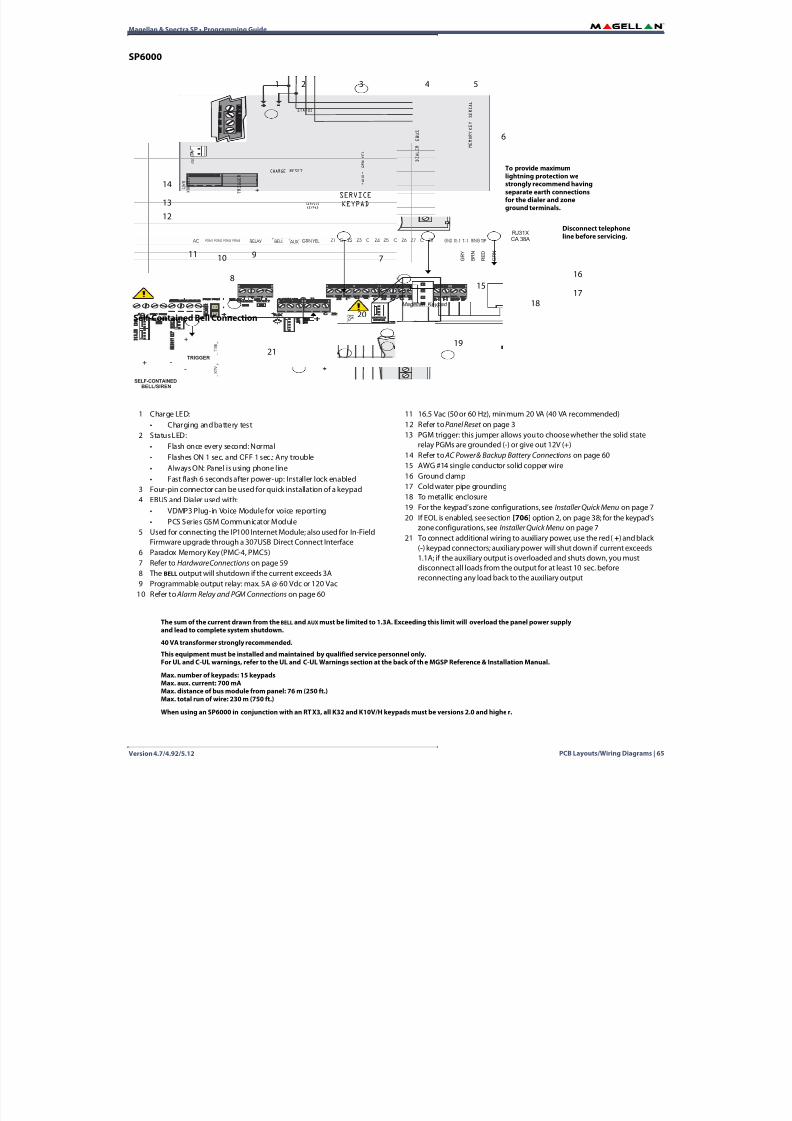
8/10/2019 Mgsp Ep27 Web
http://slidepdf.com/reader/full/mgsp-ep27-web 65/72
Magellan & Spectra SP • Programming Guide
Version 4.7/4.92/5.12 PCB Layouts/Wiring Diagrams | 65
SP6000
R E D B L K
5 A / 1 2 5 V
AC PGM1 PGM2 AUX Z2C+ - R-1 T-1 RING TIPGND
RESET
S E R I A L
M E M O R Y
K E Y
STATUS
BELL+ -
B A T T
GRN YEL Z1
D I A L E R
CHARGE
PGM4PGM3 Z3 C Z4 Z5
E B U S
RELAY C Z7 C Z8Z6
T R I G G E R
-
+
B R N
G R Y
R E D
G R N
RJ31XCA 38A
R E D
B L K
G R N
Y E L
Z O N E
Magellan Keypad
1 K
E OL
- +
SERVICE
KEYPAD
SERVICE
KEYPAD
+
A U X
-
G R N
Y E L
To provide maximumlightning protection westrongly recommend havingseparate earth connectionsfor the dialer and zoneground terminals.
1
6
11
4 53
Disconnect telephoneline before servicing.
7
8
14
1516
17
18
19
20
21
Self-Contained Bell Connection
B E L L
+
-
A U X
+
-
TRIGGER
-
+
SELF-CONTAINEDBELL/SIREN
+ -
2
13
12
910
1 Charge LED:• Charging and battery test
2 Status LED:• Flash once every second: Normal• Flashes ON 1 sec. and OFF 1 sec.: Any trouble• Always ON: Panel is using phone line• Fast flash 6 seconds after power-up: Installer lock enabled
3 Four-pin connector can be used for quick installation of a keypad4 EBUS and Dialer used with:
• VDMP3 Plug-in Voice Module for voice reporting• PCS Series GSM Communicator Module
5 Used for connecting the IP100 Internet Module; also used for In-FieldFirmware upgrade through a 307USB Direct Connect Interface
6 Paradox Memory Key (PMC-4, PMC5)7 Refer to Hardware Connections on page 598 The BELL output will shutdown if the current exceeds 3A9 Programmable output relay: max. 5A @ 60 Vdc or 120 Vac
10 Refer to Alarm Relay and PGM Connections on page 60
11 16.5 Vac (50 or 60 Hz), minimum 20 VA (40 VA recommended)12 Refer to Panel Reset on page 313 PGM trigger: this jumper allows you to choose whether the solid state
relay PGMs are grounded (-) or give out 12V (+)
14 Refer to AC Power & Backup Battery Connections on page 6015 AWG #14 single conductor solid copper wire16 Ground clamp17 Cold water pipe grounding18 To metallic enclosure19 For the keypad’s zone configurations, see Installer Quick Menu on page 720 If EOL is enabled, see section [706] option 2, on page 38 ; for the keypad’s
zone configurations, see Installer Quick Menu on page 721 To connect additional wiring to auxiliary power, use the red ( +) and black
(-) keypad connectors; auxiliary power will shut down if current exceeds1.1A; if the auxiliary output is overloaded and shuts down, you mustdisconnect all loads from the output for at least 10 sec. beforereconnecting any load back to the auxiliary output
40 VA transformer strongly recommended.
Max. number of keypads: 15 keypadsMax. aux. current: 700 mAMax. distance of bus module from panel: 76 m (250 ft.)Max. total run of wire: 230 m (750 ft.)
This equipment must be installed and maintained by qualified service personnel only.For UL and C-UL warnings, refer to the UL and C-UL Warnings section at the back of the MGSP Reference & Installation Manual.
The sum of the current drawn from the BELL and AUX must be limited to 1.3A. Exceeding this limit will overload the panel power supplyand lead to complete system shutdown.
When using an SP6000 in conjunction with an RTX3, all K32 and K10V/H keypads must be versions 2.0 and higher.
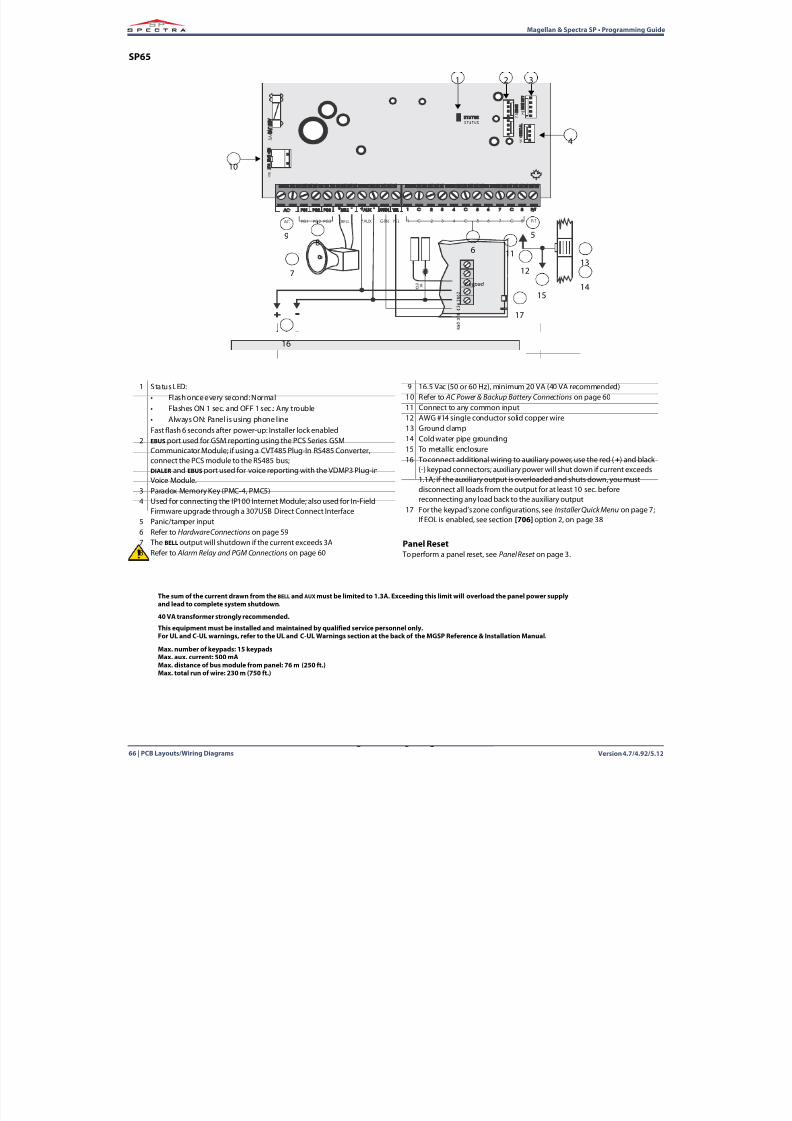
8/10/2019 Mgsp Ep27 Web
http://slidepdf.com/reader/full/mgsp-ep27-web 66/72
Version 4.7/4.92/5.1266 | PCB Layouts/Wiring Diagrams
Magellan & Spectra SP • Programming Guide
SP65
R E D
B L K
G R N
Y E L
Z O N E
Keypad
5 A / 1 2 5 V
M E M
K E Y
STATUS
1 K
E OL
- +
E B U S
R E D
B L K
B A T T
S E R I A L
AC PG1 2C AUX+ -BELL
+ -GRN YEL 1 3 C4PG2 PG3 5 6 C7 8 P/T
1 2 3
4
6
7
9
12
10
17
15
16
58
1311
14
1 Status LED:• Flash once every second: Normal• Flashes ON 1 sec. and OFF 1 sec.: Any trouble• Always ON: Panel is using phone lineFast flash 6 seconds after power-up: Installer lock enabled
2 EBUS port used for GSM reporting using the PCS Series GSM
Communicator Module; if using a CVT485 Plug-In RS485 Converter,connect the PCS module to the RS485 bus;DIALER and EBUS port used for voice reporting with the VDMP3 Plug-inVoice Module.
3 Paradox Memory Key (PMC-4, PMC5)4 Used for connecting the IP100 Internet Module; also used for In-Field
Firmware upgrade through a 307USB Direct Connect Interface5 Panic/tamper input6 Refer to Hardware Connections on page 597 The BELL output will shutdown if the current exceeds 3A8 Refer to Alarm Relay and PGM Connections on page 60
9 16.5 Vac (50 or 60 Hz), minimum 20 VA (40 VA recommended)10 Refer to AC Power & Backup Battery Connections on page 6011 Connect to any common input12 AWG #14 single conductor solid copper wire13 Ground clamp14 Cold water pipe grounding15 To metallic enclosure16 To connect additional wiring to auxiliary power, use the red ( +) and black
(-) keypad connectors; auxiliary power will shut down if current exceeds1.1A; if the auxiliary output is overloaded and shuts down, you mustdisconnect all loads from the output for at least 10 sec. beforereconnecting any load back to the auxiliary output
17 For the keypad’s zone configurations, see Installer Quick Menu on page 7 ;If EOL is enabled, see section [706] option 2, on page 38
Panel Reset To perform a panel reset, see Panel Reset on page 3 .
40 VA transformer strongly recommended.
Max. number of keypads: 15 keypadsMax. aux. current: 500 mAMax. distance of bus module from panel: 76 m (250 ft.)Max. total run of wire: 230 m (750 ft.)
This equipment must be installed and maintained by qualified service personnel only.For UL and C-UL warnings, refer to the UL and C-UL Warnings section at the back of the MGSP Reference & Installation Manual.
The sum of the current drawn from the BELL and AUX must be limited to 1.3A. Exceeding this limit will overload the panel power supply
and lead to complete system shutdown.
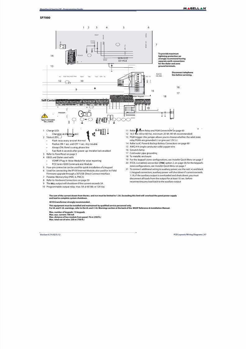
8/10/2019 Mgsp Ep27 Web
http://slidepdf.com/reader/full/mgsp-ep27-web 67/72
Magellan & Spectra SP • Programming Guide
Version 4.7/4.92/5.12 PCB Layouts/Wiring Diagrams | 67
SP7000
R E D
B L K
G R N
Y E L
Z O N E
Magellan Keypad
R E D
B L K
5 A / 1 2 5 V
R-1 T-1 RING TIPGND
RESET
S E R I A L
M E M O R Y
K E YSTATUS
B A T T
D I A L E R
CHARGE
E B U S
TRIGGER
- +
AC PGM1 PGM2 AUX+ -BELL
+ -GRN YELPGM4PGM3 RELAY
B R N
G R Y
R E D
G R N
RJ31XCA 38A
1 K
E OL
- +
SERVICE
KEYPAD
SERVICE
KEYPAD
+ A U X
-
G R N
Y E L
To provide maximumlightning protection westrongly recommend havingseparate earth connectionsfor the dialer and zoneground terminals.
1
7
12
5 64
Disconnect telephoneline before servicing.
8
9
14
1516
1718
19
20
21
Self-Contained Bell Connection
B E L L
+
-
A U X
+
-
TRIGGER
-
+
SELF-CONTAINEDBELL/SIREN
+ -
3
13
2
1110
1 Charge LED:• Charging and battery test
2 Status LED:
• Flash once every second: Normal• Flashes ON 1 sec. and OFF 1 sec.: Any trouble• Always ON: Panel is using phone line• Fast flash 6 seconds after power-up: Installer lock enabled
3 Refer to Panel Reset on page 34 EBUS and Dialer used with:
• VDMP3 Plug-in Voice Module for voice reporting• PCS Series GSM Communicator Module
5 Four-pin connector can be used for quick installation of a keypad6 Used for connecting the IP100 Internet Module; also used for In-Field
Firmware upgrade through a 307USB Direct Connect Interface7 Paradox Memory Key (PMC-4, PMC5)8 Refer to Hardware Connections on page 599 The BELL output will shutdown if the current exceeds 3A
10 Programmable output relay: max. 5A @ 60 Vdc or 120 Vac
11 Refer to Alarm Relay and PGM Connections on page 6012 16.5 Vac (50 or 60 Hz), minimum 20 VA (40 VA recommended)13 PGM trigger: this jumper allows you to choose whether the solid state
relay PGMs are grounded (-) or give out 12V (+)14 Refer to AC Power & Backup Battery Connections on page 6015 AWG #14 single conductor solid copper wire16 Ground clamp17 Cold water pipe grounding18 To metallic enclosure19 For the keypad’s zone configurations, see Installer Quick Menu on page 720 If EOL is enabled, see section [706] option 2, on page 38 ; for the keypad’s
zone configurations, see Installer Quick Menu on page 721 To connect additional wiring to auxiliary power, use the red ( +) and black
(-) keypad connectors; auxiliary power will shut down if current exceeds1.1A; if the auxiliary output is overloaded and shuts down, you mustdisconnect all loads from the output for at least 10 sec. beforereconnecting any load back to the auxiliary output
40 VA transformer strongly recommended.
Max. number of keypads: 15 keypadsMax. aux. current: 700 mAMax. distance of bus module from panel: 76 m (250 ft.)Max. total run of wire: 230 m (750 ft.)
This equipment must be installed and maintained by qualified service personnel only.For UL and C-UL warnings, refer to the UL and C-UL Warnings section at the back of the MGSP Reference & Installation Manual.
The sum of the current drawn from the BELL and AUX must be limited to 1.3A. Exceeding this limit will overload the panel power supplyand lead to complete system shutdown.
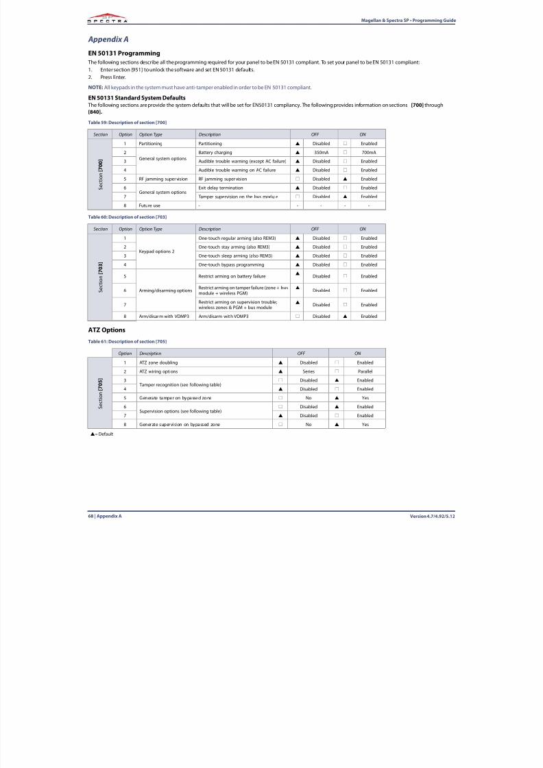
8/10/2019 Mgsp Ep27 Web
http://slidepdf.com/reader/full/mgsp-ep27-web 68/72
Version 4.7/4.92/5.1268 | Appendix A
Magellan & Spectra SP • Programming Guide
Appendix A
EN 50131 Programming The following sections describe all the programming required for your panel to be EN 50131 compliant. To set your panel to be EN 50131 compliant:1. Enter section [951] to unlock the software and set EN 50131 defaults.2. Press Enter.
NOTE:All keypads in the system must have anti-tamper enabled in order to be EN 50131 compliant.
EN 50131 Standard System Defaults The following sections are provide the system defaults that will be set for EN50131 compliancy. The following provides information on sections [700] through[840].
ATZ Options
Table 59: Description of section [700]
Section Option Option Type Description OFF ON
S e c t i o n
[ 7 0 0 ]
1 Partitioning Partitioning Disabled Enabled
2General system options
Battery charging 350mA 700mA
3 Audible trouble warning (except AC failure) Disabled Enabled
4 Audible trouble warning on AC failure Disabled Enabled
5 RF jamming supervision RF jamming supervision Disabled Enabled
6General system options
Exit delay termination Disabled Enabled
7 Tamper supervision on the bus module Disabled Enabled
8 Future use - - - - -
Table 60: Description of section [703]
Section Option Option Type Description OFF ON
S e c t i o n
[ 7 0 3 ]
1
Keypad options 2
One-touch regular arming (also REM3) Disabled Enabled
2 One-touch stay arming (also REM3) Disabled Enabled
3 One-touch sleep arming (also REM3) Disabled Enabled
4 One-touch bypass programming Disabled Enabled
5
Arming/disarming options
Restrict arming on battery failure
Disabled Enabled
6 Restrict arming on tamper failure (zone + busmodule + wireless PGM) Disabled Enabled
7 Restrict arming on supervision trouble;wireless zones & PGM + bus module Disabled Enabled
8 Arm/disarm with VDMP3 Arm/disarm with VDMP3 Disabled Enabled
Table 61: Description of section [705]
Option Description OFF ON
S e c t i o n
[ 7 0 5 ]
1 ATZ zone doubling Disabled Enabled
2 ATZ wiring options Series Parallel
3 Tamper recognition (see following table)
Disabled Enabled
4 Disabled Enabled
5 Generate tamper on bypassed zone No Yes
6Supervision options (see following table)
Disabled Enabled
7 Disabled Enabled8 Generate supervision on bypassed zone No Yes
= Default
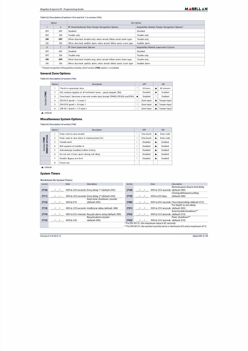
8/10/2019 Mgsp Ep27 Web
http://slidepdf.com/reader/full/mgsp-ep27-web 69/72
Magellan & Spectra SP • Programming Guide
Version 4.7/4.92/5.12 Appendix A | 69
General Zone Options
Miscellaneous System Options
System Timers
Table 62: Description of options 3 & 4 and 6 & 7, in section [705]
Option Description
3 4 RF Zone/Hardwired Zone Tamper Recognition Options Keypad/Bus Module Tamper Recognition Options*
OFF OFF Disabled Disabled
OFF ON Trouble only Trouble only
ON OFF When disarmed: trouble only; when armed: follow zone’s alarm type Trouble only
ON ON When disarmed: audible alarm; when armed: follow zone’s alarm type Audible alarm
6 7 RF Zone Supervision Options Keypad/Bus Module Supervision OptionsOFF OFF Disabled Disabled
OFF ON Trouble only Trouble only
ON OFF When disarmed: trouble only; when armed: follow zone’s alarm type Trouble only
ON ON When disarmed: audible alarm; when armed: follow zone’s alarm type Audible alarm
* Tamper recognition of keypad/bus module, only if section [700] , option 7, is enabled.
Table 63: Description of section [706]
Option Description OFF ON
S e c t i o n
[ 7 0
6 ]
1 Check-in supervision time 24 hours 80 minutes
2 EOL resistors (applies to all hardwired zones – panel, keypad, ZX8) Disabled Enabled
3 Zone input 1 becomes a two-wire smoke input (except SP4000, SP5500, and SP65) Disabled Enabled
4 ZX8 ID A (panel + 1) input 1 Zone input Tamper input
5 ZX8 ID B (panel + 9) input 1 Zone input Tamper input
6 ZX8 ID C (panel + 17) input 1 Zone input Tamper input
= Default
Table 64: Description of section [708]
Option Description OFF ON
S e c t i o n [
7 0 8 ]
E N 5 0 1 3 1 O
P T I O N S
1 Enter code to view trouble One-touch Enter code
2 Enter code to view alarm in memory/event list One-touch Enter code
3 Trouble latch Disabled Enabled4 Bell squawk on Installer in Disabled Enabled
5 Acknowledge trouble(s) before arming Disabled Enabled
6 Do not arm if zone opens during exit delay Disabled Enabled
7 Disable ‘Bypass and Arm’ Disabled Enabled
8 Future use - - - -
= Default
Worksheet 56: System TimersSection Data Description Section Data Description
[710] ___/___/___ 000 to 255 seconds Entry delay 1* (default: 045) [718] ___/___/___ 000 to 255 seconds
Remote panic disarm lock delay
(default: 000)
[711] ___/___/___ 000 to 255 seconds Entry delay 2* (default: 045) [719] ___/___/___ 000 to 255 daysClosing delinquency delay(default: 000)
[712] ___/___/___ 000 to 015Auto-zone shutdown counter(default: 005) [720] ___/___/___ 000 to 255 seconds Flex-instant delay (default: 015)
[713] ___/___/___ 000 to 255 seconds Intellizone delay (default: 048) [721] ___/___/___ 000 to 255 secondsFor StayD: re-arm delay(default: 005)
[714] ___/___/___ 000 to 255 minutes Recycle alarm delay (default: 000) [722] ___/___/___ 000 to 255 secondsAuto trouble shutdown**(default: 010)
[715] ___/___/___ 000 to 255Recycle alarm counter(default: 000) [723] ___/___/___ 000 to 255 seconds
Panic shutdown**(default: 010)
* For EN 50131, the maximum value is 45 seconds.** For EN 50131, the section must be set to a minimum of 3 and a maximum of 10
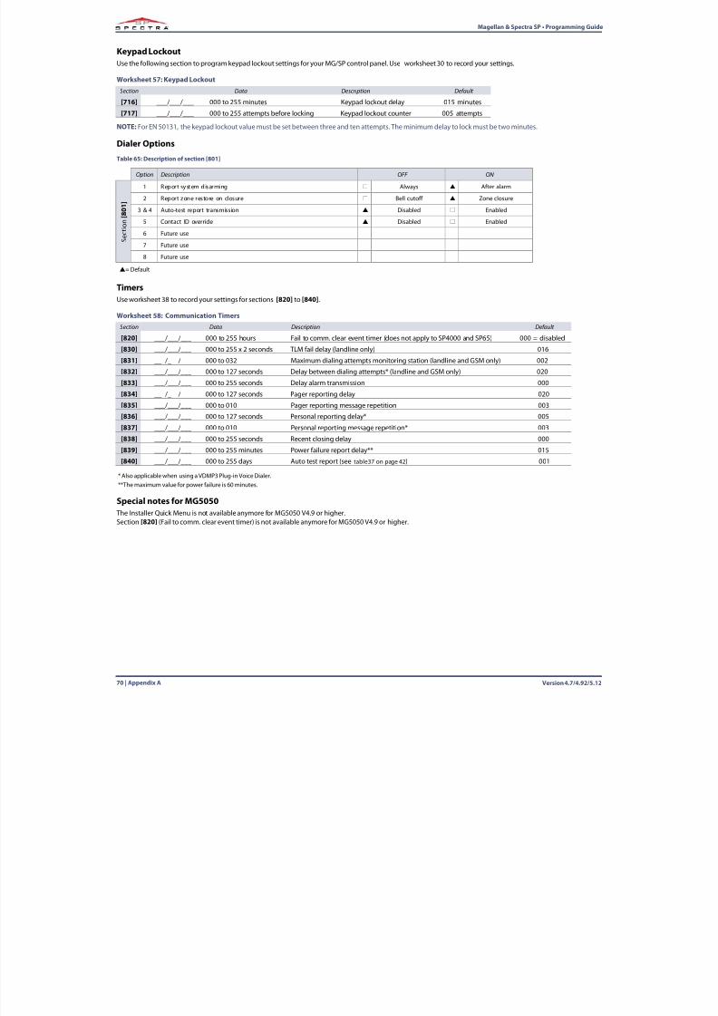
8/10/2019 Mgsp Ep27 Web
http://slidepdf.com/reader/full/mgsp-ep27-web 70/72
Version 4.7/4.92/5.1270 | Appendix A
Magellan & Spectra SP • Programming Guide
Keypad LockoutUse the following section to program keypad lockout settings for your MG/SP control panel. Use worksheet 30 to record your settings.
NOTE:For EN 50131, the keypad lockout value must be set between three and ten attempts. The minimum delay to lock must be two minutes.
Dialer Options
TimersUse worksheet 38 to record your settings for sections [820] to [840] .
Special notes for MG5050 The Installer Quick Menu is not available anymore for MG5050 V4.9 or higher.Section [820] (Fail to comm. clear event timer) is not available anymore for MG5050 V4.9 or higher.
Worksheet 57: Keypad LockoutSection Data Description Default
[716] ___/___/___ 000 to 255 minutes Keypad lockout delay 015 minutes
[717] ___/___/___ 000 to 255 attempts before locking Keypad lockout counter 005 attempts
Table 65: Description of section [801]
Option Description OFF ON
S e c t i o n
[ 8 0 1 ]
1 Report system disarming Always After alarm
2 Report zone restore on closure Bell cutoff Zone closure
3 & 4 Auto-test report transmission Disabled Enabled
5 Contact ID override Disabled Enabled
6 Future use
7 Future use
8 Future use
= Default
Worksheet 58: Communication TimersSection Data Description Default
[820] ___/___/___ 000 to 255 hours Fail to comm. clear event timer (does not apply to SP4000 and SP65) 000 = disabled
[830] ___/___/___ 000 to 255 x 2 seconds TLM fail delay (landline only) 016
[831] ___/___/___ 000 to 032 Maximum dialing attempts monitoring station (landline and GSM only) 002
[832] ___/___/___ 000 to 127 seconds Delay between dialing attempts* (landline and GSM only) 020
[833] ___/___/___ 000 to 255 seconds Delay alarm transmission 000
[834] ___/___/___ 000 to 127 seconds Pager reporting delay 020
[835] ___/___/___ 000 to 010 Pager reporting message repetition 003
[836] ___/___/___ 000 to 127 seconds Personal reporting delay* 005
[837] ___/___/___ 000 to 010 Personal reporting message repetition* 003
[838] ___/___/___ 000 to 255 seconds Recent closing delay 000
[839] ___/___/___ 000 to 255 minutes Power failure report delay** 015
[840] ___/___/___ 000 to 255 days Auto test report (see table37 on page 42 ) 001
* Also applicable when using a VDMP3 Plug-in Voice Dialer.**The maximum value for power failure is 60 minutes.

8/10/2019 Mgsp Ep27 Web
http://slidepdf.com/reader/full/mgsp-ep27-web 71/72

8/10/2019 Mgsp Ep27 Web
http://slidepdf.com/reader/full/mgsp-ep27-web 72/72
The whole Paradox team wishes you a successful and easy installation. We hope this product performs to your complete satisfaction. Should you have any questionsor comments, please contact us.
For support, please contact your local distributor, or dial 1-800-791-1919 (in North America) or
+1-450-491-7444 (outside North America), Monday to Friday, from 8:00 a.m. to 8:00 p.m. EST.You may also e-mail us at [email protected] .
Additional information can be found at PARADOX.COM