mice spectrometer solenoid (pre-) review ini9al … · 2015-10-29 · m1 m2 e1 c e2 10/27/15 j s...
TRANSCRIPT

MICESpectrometerSolenoid(Pre-)Review
Ini9alImpressionsJimKerby(ANL)RAL,Oct27,2015
Onbehalf(butnotchecking)ofTomTaylor(CERN,ret.),AmalliaBallarino(CERN),Vladimir
Kashikhin(FNAL),AndrewTwin(OxfordInstruments),andJosefBoehm(RAL)WiththankstoKen,Alan,Steve,Soren,RoyandMarkfortalks(&slides)yesterday

Outline
• Summaryofwhathappened• What’snext?– WhatdoesMICEneed?– Whatarereasonablepathsforward?
• NextfortheadhoccommiYee(+?)
• àifit’singreenit’sanimpression.Ifit’snotIgrabbedtheslideandprobablyhavenotgivenappropriatecredittothespeakerinthisset(apologiesinadvance)
10/27/15 JSKerby 2

Reminder:Basicdesign
3
• 52-stageCCs• 1single-stageCC• 5Coils• Maxcurrent~300A• Highinductance
10-40H
M2M1 E2CE1
10/27/15 JSKerby

4
Quench
Normal zone growth
Detection
Power supply
switched off Protection heaters Extraction Quenchback
Trigger protection options
The faster this chain happens the safer is the magnet
Current decay in the magnet
Magnetic energy
Converted to heat by Joule heating
MagnetProtec9on:basicscenarios
10/27/15 JSKerby

Title
Size Document Number Rev
Date: Sheet of
<Doc> 0
SCHEMATIC - MICE MAGNET POWER SUPPLY SYSTEM
B
1 1Thursday, February 16, 2012
20V @ 300APOWER SUPPLY
PS3
POWER TEN 300A PS
OUT +
OUT -
D03
K3EEC225 - 315A
K4EEC225 - 315A
TBD
+/-5V @ +/-60A
+/-5V @ +/-60A
K2CONTACTOR
1 1
K8EEC50-A [80A]
FAST DISCHARGESWITCH
FAST DISCHARGESWITCH
FAST DISCHARGESWITCH
R6200140XX00
DA2-BCHARGEABSORBER3 DIODE
P3
P4
XPR20-300
XPR20-300
100
TRIM E1
LAKESHORE 625OUT +
OUT -
100
TRIM E2
LAKESHORE 625OUT +
OUT -
AMI 420
L=12.9HEND 2
Rc=111
L=43.8H
CENTERRc=195
Rc=203
AMI 420
L=10.5HEND 1
Rc=100
1 1
K1CONTACTOR
AMI 420
P63C-20330
VTM07FTP-G
1
VTM08FTP-H
1
1 1
11
VTM09FTP-J
1
1
VTM05FTP-E
1
HTS LEADPROTECTION
VTM01FTP-A
1
VTM04FTP-D
1
HTS LEADPROTECTION
HTS LEAD - E1
HTS LEADPROTECTION
DA2
VTM02FTP-B
1
TBD
K7EEC50-A [80A]
1 1TBD
HTS LEADPROTECTION
HTS LEAD - F
11 HTS LEAD - G
HTS LEAD - H
HTS LEADPROTECTION
L=6.8HMATCH 2
Rc=85
1 1
HTS LEAD - C
HTS LEAD - D
R9
0.008
R8
0.008
K6E
EC
225
- 315
A
DA3DISCHARGE
8 DIODEABSORBER
P1
P2
CS3
PS CONTROLLEROUT +
OUT -
CRYOSTAT
TBD
K5EEC225 - 315A
TBD
DA4CHARGE
8 DIODEABSORBER P1P2
R5
0.008
10 Ohm / 50W
20V@300APOWER SUPPLY
PS2
XANTREX 300A PS
OUT +
OUT -
D02
CS2
PS CONTROLLEROUT +
OUT -
10 Ohm / 50W
DA1-BCHARGEABSORBER3 DIODE
P3
P4
DA1 L=15.7HMATCH 1
Rc=136
VTM03FTP-C
1
HTS LEAD - A
HTS LEAD - B
R7
0.008
R6
0.008
20V@300APOWER SUPPLY
PS1
XANTREX 300A PS
OUT +
OUT -
D3
CS1
PS CONTROLLEROUT +
OUT -
10 Ohm / 50W
DA1-ADISCHARGEABSORBER3 DIODE
P1
P2
VTM06FTP-F
1
R4
0.008
DA2-ADISCHARGEABSORBER3 DIODE
P1
P2
R3
0.008
R2
0.008
R1
0.008
LBNL/MICE: DC PATH [“As Built”]
• Added 5 contactors to system – HTS Lead protection during fast discharge
10/27/15 JSKerby 5

Schema9csas-operated
10/27/15 JSKerby 6
5
5
4
4
3
3
2
2
1
1
D D
C C
B B
A A
Title
veRrebmuN tnemucoDeziS
teehS:etaD of
<Doc>
SCHEMATIC - MICE MAGNET POWER SUPPLY SYSTEM
B
1 1
Title
veRrebmuN tnemucoDeziS
teehS:etaD of
<Doc>
SCHEMATIC - MICE MAGNET POWER SUPPLY SYSTEM
B
1 1
Title
veRrebmuN tnemucoDeziS
teehS:etaD of
<Doc>
SCHEMATIC - MICE MAGNET POWER SUPPLY SYSTEM
B
1 1
+/-5V @ +/-60A
+/-5V @ +/-60A
DA2
DA1
FAST DISCHARGESWITCH
FAST DISCHARGESWITCH
FAST DISCHARGESWITCH
HTS LEADPROTECTION
HTS LEADPROTECTION
CRYOSTAT
AMI 420
AMI 420
AMI 420
0/20/2 2/0
2/0
2/0
2/0
2/0
A
B
2/0
C
D
H
G
F
E
L=15.7HMATCH 1
Rc=136L=15.7HMATCH 1
Rc=136
1
R1
0.008
R1
0.008
1DA2-BCHARGEABSORBER3 DIODE
P3
P4
100
TRIM E2
LAKESHORE 625
100
TRIM E2
LAKESHORE 625OUT +
OUT -
1
K8EEC50-A [80A]
K8EEC50-A [80A]
1
DA3DISCHARGE
8 DIODEABSORBER
P1
P2
R8
0.008
R8
0.008
VTM02FTP-BVTM02FTP-B
1 R2
0.008
R2
0.008
K1EEC225 - 315A
K1EEC225 - 315A
1
1
VTM05FTP-EVTM05FTP-E
1PS3
20V @ 300A
TDK-Lambda
POWER SUPPLY
PS3
TD
OUT +
OUT -
K2EEC225 - 315A
K2EEC225 - 315A
R3
0.008
R3
0.008
D01D01
1
1
L=12.9HEND 2
Rc=111L=12.9HEND 2
Rc=111CS3
PS CONTROLLER
CS3
PS CONTROLLEROUT +
OUT -
R6
0.008
R6
0.008
20 /
50W
@ C
RY
OS
TAT
20 /
50W
@ C
RY
OS
TAT
D03D03
R4
0.008
R4
0.008VTM03FTP-CVTM03FTP-C
1
R7
0.008
R7
0.008
DA1-ADISCHARGEABSORBER3 DIODE
P1
P2
1
D02D02
K3EEC225 - 315A
K3EEC225 - 315A
HTS LEAD - GHTS LEAD - G
PS2PS2 OUT +
OUT -
CS1
PS CONTROLLER
CS1
PS CONTROLLEROUT +
OUT -
20 /
50W
@ C
RY
OS
TAT
20 /
50W
@ C
RY
OS
TAT
VTM04FTP-DVTM04FTP-D
1
VTM09FTP-JVTM09FTP-J
1
HTS LEAD - AHTS LEAD - A
1
20 /
50W
@ C
RY
OS
TAT
20 /
50W
@ C
RY
OS
TAT
L=43.8H
CENTERRc=195
Rc=203L=43.8H
CENTERRc=195
Rc=203
VTM07FTP-GVTM07FTP-G
1
20 /
50W
@ C
RY
OS
TAT
20 /
50W
@ C
RY
OS
TAT
20 /
50W
@ C
RY
OS
TAT
20 /
50W
@ C
RY
OS
TAT
HTS LEAD - DHTS LEAD - D
HTS LEAD - CHTS LEAD - C
L=6.8HMATCH 2
Rc=85L=6.8HMATCH 2
Rc=85
HTS LEAD - BHTS LEAD - B
1
1 HTS LEAD - EHTS LEAD - E
100
TRIM E1
LAKESHORE 625
100
TRIM E1
LAKESHORE 625OUT +
OUT -
K7EEC50-A [80A]
K7EEC50-A [80A]
R5
0.008
R5
0.008
VTM06FTP-FVTM06FTP-F
1
PS1PS1 OUT +
OUT -
L=10.5HEND 1
Rc=100L=10.5HEND 1
Rc=100
VTM01FTP-AVTM01FTP-A
1
HTS LEAD - FHTS LEAD - F
R6200140XX00R6200140XX00
1
DA2-ADISCHARGEABSORBER3 DIODE
P1
P2
1
DA1-BCHARGEABSORBER3 DIODE
P3
P4
DA4CHARGE
8 DIODEABSORBER P1P2
R9
0.008
R9
0.008
HTS LEAD - HHTS LEAD - H
1
1
VTM08FTP-HVTM08FTP-H
1
CS2
PS CONTROLLER
CS2
PS CONTROLLEROUT +
OUT -
20V @ 300A
TDK-Lambda
POWER SUPPLY
20V @ 300A
TDK-Lambda
POWER SUPPLY

TrainingSSD
• SSDhasbeenabitproblema9catRAL– Somevacuumissues– LostvoltagetaponLTSleadofM2coil
• InthetrainingrunofSeptember13th,2015allwasgoingverywell.– Implementa9onofaddi9onalQPfortheM2leadhadnotyetbeendone,soadecisionwasmadetoramponlyM1andECE
– Aquenchoccurredat~260AinECE(muchhigherthanexpected,nextslide).
• QPsystemperformedasexpected,nothingoutwardlyunusualexceptforthelargecurrent.
710/27/15 JSKerby

Leadfailure
• However,uponenteringthehalltheodorofburntFR4/G10wasextremelystrong.StrongestatHereliefvalve
• Aferagreatdealofanalysis,ithasnowbeendeterminedthat(seediagramonnextslide):– OnelegofM1deadshorttoground.ThisisLTSAlead.– LTSBleadnotconnectedtocoil(open),butconnectedtoLTSAwith~
2.4KOhmresistance.– M2coilOK.– Nodamageseenanywhereelse.
• However,M2coilhas1.3KOhmresistancetoM1(&ground)– ACmeasurementsshowthatQPonM1notac9veindica9ngabreakin
theinternalQPcircuit.Mostlikelypointisindicatedinthefigureonthenextslide(xnexttodiodes)becausethereisanothershorttogroundonthislegofthecircuit.
– AllothercoilsOK(includingtheirQPcircuit).
8JSKerby10/27/15

M1circuitaferfault
9JSKerby
DiagramoftheM1circuit.Resistance(fourwireandtwowire)measurementsrevealed:i)LeadAhashardshorttoground,ii)LTSBisshortedtoLTSAthrough2.4kOhmsandLTSBisnotconnectedtotheM1coilontheLeadBside.
10/27/15
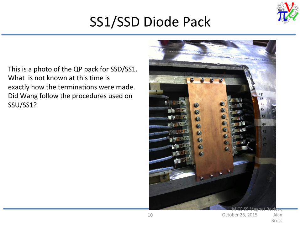
SS1/SSDDiodePack
10MICESSMagnetReview,
October26,2015AlanBross
ThisisaphotooftheQPpackforSSD/SS1.Whatisnotknownatthis9meisexactlyhowthetermina9onsweremade.DidWangfollowtheproceduresusedonSSU/SS1?

Feedthrough
10/27/15 JSKerby 11

Summary
Manycontribu9ngfactors(innopar9cularorder):• QAatvendor• Electricalsystemimplementa9on• NotpoweringM2,causingadelayinquenchback
AlltogetheràM1failure
10/27/15 JSKerby 12

GoingForward
• WhatdoesMICEneed?• Whatcanbedone?
10/27/15 JSKerby 13

WhatdoesMICEneed?
• MICEprogramme:– StepIV:
• Measurementofmaterialproper9es• Observa9onofreduc9oninnormalisedtransverseemiYance
– Coolingdemonstra9on:• Studyofcoolingdemonstra9oneffect
• PrincipalcomponentsofStepIVprogrammecanbe(andcurrentlyarebeing)carriedoutw/oSSD/M1
• Coolingdemonstra9onrequiresrecoveryoffullfunc9onalityofSSD
1410/27/15 JSKerby

WhatCanBeDone?
• AddressingtheKeyQues9ons1. StepIV?2. RepairPath?3. Schedule?4. Cost?5. Risks?
10/27/15 JSKerby 15

1.StepIV?
CanweoperateMICEStepIVwiththeSSDasis?• Op9csdesignssufficientforcharacterizingabsorbermaterialsareinhand
(assumingSSDM2coilisopera9onal):– Cri9calSSDchecks:
• SSDE-C-Equenchandreasonableresponseofvessela Hevesselandfeedthroughintegritysa9sfactory
• SSDM2lowcurrentcheckouta Noanomalousresis9vebehaviorobserved– Nextstepisacarefulramptohighcurrent
a Viableop9csandlikelyviablemagnetwithM2andE-C-Ecoils• PlanistoproceedwithmodifiedStepIVrunplanfor~1year
a Timetoprepareforarepair
Answer: YES– Caveats:
• S9llneedtovalidatemagnetatcurrentsrequiredbyalterna9veop9cs• Needtoconfirmthatwehaveapowersupplyconfigura9onthatis“safe”foropera9ons
10/27/15 JSKerby 16

• Quad model built in VF • Quench initiated in the
inner layer of the E2 coil.
• All coils are powered by a single powers supply.
• A 20 Ω external resistor goes across all the coils.
• Switch opened when the overall voltage across the E2 coil exceeds 0.2V.
PSUConfigura9on(PreliminaryforSSU)
HengPan(LBNL)
10/27/15 JSKerby 17

CommiYeeIni9alComment
• WesuggestnofurtherfullpoweringofSSDorSSUoccurun9larevisedpowersystemisdesigned,understood,tested,andimplemented.
• ProceedingwiththeStepIVprogramisprobablyfineaferthischange.– Riskforfurtherincrementaldamageisprobablycontainedtotheareaalreadydamagedandinneedofrepair.
– Someno9ceablepor9onofStepIVcanbeaccomplishedwithoutM1orM2ifneeded...
10/27/15 JSKerby 18

Poten9alTechnicalPathsForward
• Op9on1–Repeatpreviousrepairscenario– Assump9ons
• NOchangestomagnetdesign• RepairstartsatconclusionofStepIVrunning• Suitablerepairteamavailable–magnetmovedtoteamloca9on
– Schedule• MagnetcouldbeatRALforinstalla9on/commissioningpriortoendofUSFY17.WouldfullybecomeRALresponsibilityatendofUSFY17.
– Cost• Nominallyappearstouse100%ofMAPmanagementreservefunds.Plausible.
– Risk• QAissues(believedtobeknown)couldbeaddressed• Surpriseswhencoldmassisinspected?• Arewecomfortablewiths9ckingtothecurrentdesignuntouched?
10/27/15 JSKerby 19

Poten9alTechnicalPathsForward• Op9on2–Fabricatenewcoldmass
– Assump9ons• Onlyallowmodestchangestocoldmassdesign
– Examples:» Minorchangeinbobbinlengthtocontrolthermaldistor9on» Allowforvacuum-impregna9onofcoils» Allowforaddi9onofac9vequenchheaters
• Integra9onwithexis9ngcryostatstartsatconclusionofStepIVrunning• Allrequiredsuperconductorisonhand(enoughSCisinFNALstoragetowind2newcoldmasses)
– Schedule• Coldmassfabrica9oncouldstartassoonasreviseddrawingsapproved.• BudgetaryquotefromAlforgingvendorindicates10weekdelivery.• WithSConhand,newcoldmasscouldbemachined,woundandousiYedbeforeAugust1,2016(preliminary
es9mateof8months)• Poten9allycouldbecold-tested/trainedindewarinadvanceof
August1,2016(arealis9cscheduleneedstobeconfirmed)– Couldalsobecarriedoutwhilemagnetdisassemblyunderway
• FinalInstalla9on– Installa9onofpreppedcoldmasswouldlikelysave~2monthsinbaselinedisassembly/reassemblyschedulefor
magnet(vs.slide8)– Atrainedcoldmasswouldlikelysave~3weeksintraining9me(vs.slide8)
– Consistentwithcomple9onbeforeendofUSFY17
10/27/15 JSKerby 20

Poten9alTechnicalPathsForward
• Op9on2(cont’d)–Fabricatenewcoldmass– Cost
• Verypreliminaryes9mateof$500KtoprepareanewcoldmasswithSConhand
• Wouldwewanttowind2coldmassesasriskmi9ga9on???• Woulds9llrequiremostofthe$700Kbasecostes9matetodisassemble/reassemblethemagnet
– Risk• Achancetoaddressiden9fiedriskswithminimalmodifica9ons• Tes9ngbeforeinstalla9onwouldprovidecertainty–however,onlyonechanceisrealis9cunless2bobbinsareprepped
• Opportunity–Poten9alreduc9onintrainingcosts(save~$150K)• Opportunity–Possibilityofretrofiungexis9ngSSDcoldmassasaspareaferSSDrepaircomplete
10/27/15 JSKerby 21

Poten9alTechnicalPathsForward
• Op9on3–DoNOrepairandinsteadinsertanothersolenoidinthecoolingchannel
10/27/15 JSKerby 22
Demonstra9onofMuonIoniza9onCooling(Re-baseline)
Insert1-or2-coilsolenoidhereanddevelopnewmatchop9cswithoutSSDM1.
SSDSS

Poten9alTechnicalPathsForward• Op9on3(cont’d)
– Assump9ons• Magnetcanhandlelongitudinalforcesofcoolingchannel• Magnetcryostatcanbemodifiedforintegra9onintocoolingchannel• Magnetboreissufficientlylarge• MagnetcoolingcanbemanagedintheRALHall
(Isthereamagnetavailablewhichcanbeoperatedwithoutarefrigeratorsystem?–noneavailableatRALrightnow)
– Schedule• Oneyeartoprepmagnet• OneyeartoprepPRYmodifica9ons• Installa9onshouldbefast
– Cost• Wouldrequirefurthermodifica9ontothePRYextension• Wouldrequireaddi9onaldesignandfabrica9onworktointegratethenewmagnet
– Risk• ModestaslongasbothSSUandSSDopera9ngreasonablythruStepIV• (SSDinit’scurrentformwouldremain;M2has1.3kohmresistancetoM1/ground)
Possibili9es:MuCoolTestAreaMagnet;newFC
10/27/15 JSKerby 23

Poten9alTechnicalPathsForward
• Op9on4–CutSSDopen(throughvacuumvessel,sheild,coldmass)andrepair– Assump9ons
• Wouldrequireacquisi9onofusedrefrigeratorbecausethermallosseslikelytoexceedwhatcouldbehandledwithcryocoolers
• Wouldrequiremodifica9onstoworkwithrefrigera9onsystem– Schedule
• Rela9velyfastassumingthatrefrigera9onsystemcouldbeinstalled/commissionedduringStepIVrunning
– Costs• TBD• U9lizesurplusrefrigeratorsystemtocontroloverallcosts
– Risks• Notclearthatthiscouldbedonesafelywithoutdamagingthecoldmasssupportstructure
10/27/15 JSKerby 24

Poten9alTechnicalPathsForward
• Op9on5–Construc9onofnewSSmagnet– Assump9ons
• Wouldallowforimplementa9onof(some)lessonslearned• Wouldnotallowforamajorchangeinconfigura9ontoamorereliablemagnetstyle(e.g.highcurrentSCcablewithrefrigerator)
– Schedule• Difficulttoimagineascenario,withpropercon9ngencyassessment,thatcoulddeliveramagnetin9me
– Costs• Difficulttoimagineascenariowherecostswouldnotbesignificantlyhigherthanasimplerepair
– Risks• Dependingonscaleofmodifica9onsfrompresentdesign,wouldrequireanen9relynewtestprogram
10/27/15 JSKerby 25

CommiYeeIni9alComment
• Op9ons4and5donotappearviablefortechnicalorfundingissues.
• Op9on3requiresmorebeamphysicsstudiesforstartersandcompleteunderstandingofhallinterfaces
• Op9on1looksleastexpensive(?)• Op9on2buyssomescheduleandpoten9allybeYerperformanceofoneoftheinstalledSS
10/27/15 JSKerby 26

CommiYeeIni9alComment
• MICEcollabora9onhasdoneconsiderableworkinthepastmonthtounderstandproblem
• WhiletheSSprobablyincludesabasicdesignproblem,theassemblywastestedsufficientlytoassuresomeconfidence
• ThefailuremayhaveresultedfromnothavingaclearunderstandingoftheactualmarginintheSSconcerningquenchbackandtheintegra9onoftheSSDwiththeoverallpowersupply/systemandhavingM2notpowered
• StepIVappearsachievablewithminimalincrementalrisk• BeyondStepIVthereareseveralop9ons(2,1,3),thoughat
most3lookviableanddeservefurtherreviewoverthenextmonth(no9ngthat2and1arecloselyrelated).
• WelookforwardtomoredetaileddiscussionNov23-24
10/27/15 JSKerby 27

10/27/15 JSKerby 28

Protec9oncircuit:diodes+resistors• >3Vforwardvoltagedrop(needstobemeasuredcold)
– Forwardvoltagedropdecreasesastemperatureofdiodesincreases
• Resistor:stripofStainlessSteel– Designedtocomfortablysupportbypasscurrentduring“normal”quenchdecay(~6s)– Temperatureriseduring~6sdecayis<~300K
10/27/15 JSKerby 29

Analysis
• Quenchini9atedonECEandini9allyproceedednormally– ThereisnoevidencethatanyLTSleadswereinvolvedini9ally
• At~20sec,theinternalQPforcoilM1failed– Thevoltageonthecoilincreasedrapidlyand,itappearsthatanarcattheLTSpowerfeedthrough(fromvacuumtoLHevolume)occurredwhichburnedouttheleadandeffectedM2(thepowerleadsforM1andM2u9lizethesame4pinfeedthrough).
• WhatcausedtheQPfailure?
30JSKerby10/27/15