michele zorzi, professore, cnit / università degli studi
TRANSCRIPT

Michele Zorzi, Professore, CNIT / Università degli Studi di Padova
CNIT Talk: The New Radio
14 Rec. ITU-R M.2083-0
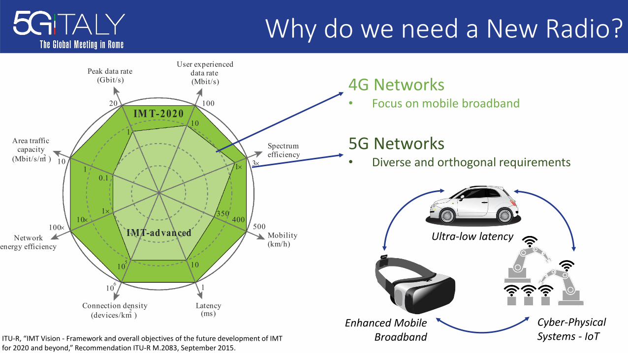
FIGURE 3 Enhancement of key capabilities from IMT-Advanced to IMT-2020
M.2083-03
User experienceddata rate(Mbit/s)
100
Spectrumefficiency
IM T-2020
3´
500
1106
10
20
100´Mobility(km/h)
Latency(ms)
Connection density(devices/km )
2
Networkenergy efficiency
Area trafficcapacity
(Mbit/s/m )2
Peak data rate(Gbit/s)
10
1´
400350
10105
10´1´
10.1
1
IMT-advanced
The values in the Figure above are targets for research and investigation for IMT-2020 and may be further developed in other ITU-R Recommendations, and may be revised in the light of future studies. The targets are further described below.
The peak data rate of IMT-2020 for enhanced Mobile Broadband is expected to reach 10 Gbit/s. However under certain conditions and scenarios IMT-2020 would support up to 20 Gbit/s peak data rate, as shown in Fig. 3. IMT-2020 would support different user experienced data rates covering a variety of environments for enhanced Mobile Broadband. For wide area coverage cases, e.g. in urban and sub-urban areas, a user experienced data rate of 100 Mbit/s is expected to be enabled. In hotspot cases, the user experienced data rate is expected to reach higher values (e.g. 1 Gbit/s indoor).
The spectrum efficiency is expected to be three times higher compared to IMT-Advanced for enhanced Mobile Broadband. The achievable increase in efficiency from IMT-Advanced will vary between scenarios and could be higher in some scenarios (for example five times subject to further research). IMT-2020 is expected to support 10 Mbit/s/m2 area traffic capacity, for example in hot spots.
The energy consumption for the radio access network of IMT-2020 should not be greater than IMT networks deployed today, while delivering the enhanced capabilities. The network energy efficiency should therefore be improved by a factor at least as great as the envisaged traffic capacity increase of IMT-2020 relative to IMT-Advanced for enhanced Mobile Broadband.
IMT-2020 would be able to provide 1 ms over-the-air latency, capable of supporting services with very low latency requirements. IMT-2020 is also expected to enable high mobility up to 500 km/h with acceptable QoS. This is envisioned in particular for high speed trains.
Finally, IMT-2020 is expected to support a connection density of up to 106/km2, for example in massive machine type communication scenarios.
4G Networks• Focus on mobile broadband
Why do we need a New Radio?
5G Networks• Diverse and orthogonal requirements
Ultra-low latency
Enhanced Mobile Broadband
Cyber-Physical Systems - IoTITU-R, “IMT Vision - Framework and overall objectives of the future development of IMT
for 2020 and beyond,” Recommendation ITU-R M.2083, September 2015.
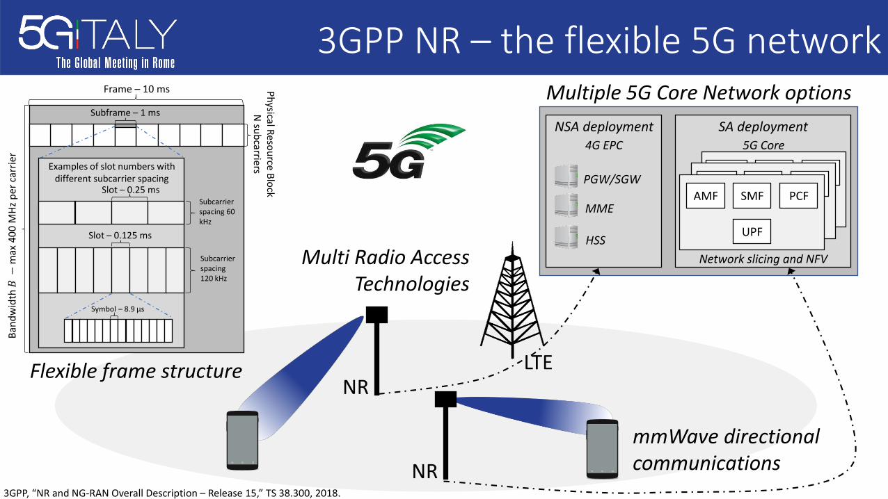
3GPP NR – the flexible 5G networkBa
ndw
idth
𝐵−
max
400
MHz
per
carr
ier
Frame – 10 ms Physical Resource Block N
subcarriers
Subframe – 1 ms
Examples of slot numbers with different subcarrier spacing
Subcarrier spacing 60 kHz
Slot – 0.25 ms
Subcarrier spacing 120 kHz
Slot – 0.125 ms
Symbol – 8.9 μs
Flexible frame structure LTE
SA deployment5G Core
NSA deployment4G EPC
PGW/SGW
MME
HSSNetwork slicing and NFV
AMF SMF
UPF
PCFAMF SMF
UPF
PCFAMF SMF
UPF
PCF
Multiple 5G Core Network options
mmWave directional communications
Multi Radio Access Technologies
NR
NR3GPP, “NR and NG-RAN Overall Description – Release 15,” TS 38.300, 2018.

Flexible frame structure
time
Multiple OFDM numerologies Integration of different use cases in the same technology framework
Self-contained subframe
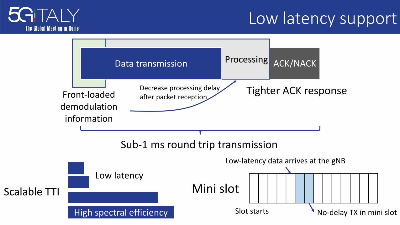
Low latency support
Tighter ACK responseFront-loaded demodulation
information
ACK/NACKProcessingData transmission
Decrease processing delay after packet reception
Sub-1 ms round trip transmission
Mini slot
Low-latency data arrives at the gNB
Slot starts No-delay TX in mini slot
Scalable TTI
High spectral efficiency
Low latency
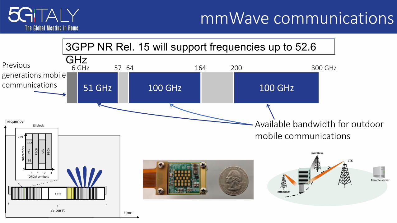
mmWave communications3GPP NR Rel. 15 will support frequencies up to 52.6 GHz
51 GHz
6 GHz
100 GHz 100 GHz
300 GHz57 64 164 200
Available bandwidth for outdoor mobile communications
Previous generations mobile communications
SS burst
0
239
0 1 2 3
subc
arrie
rs
OFDM symbols
PSS
SSS
PBCH
PBCH
182
56
SS block
…
frequency
time
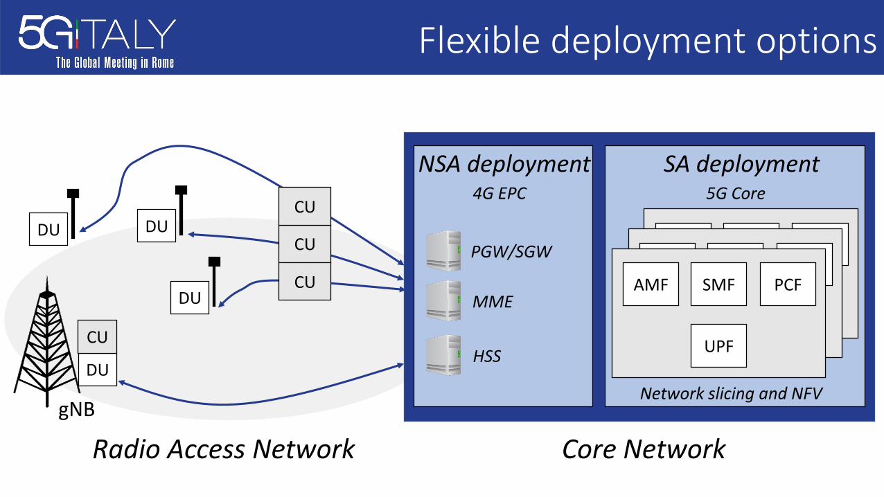
Flexible deployment options
SA deployment5G Core
NSA deployment4G EPC
PGW/SGW
MME
HSS
Network slicing and NFV
AMF SMF
UPF
PCFAMF SMF
UPF
PCFAMF SMF
UPF
PCF
gNB
Core NetworkRadio Access Network
DUDU
DU
CU
CU
CU
DU
CU
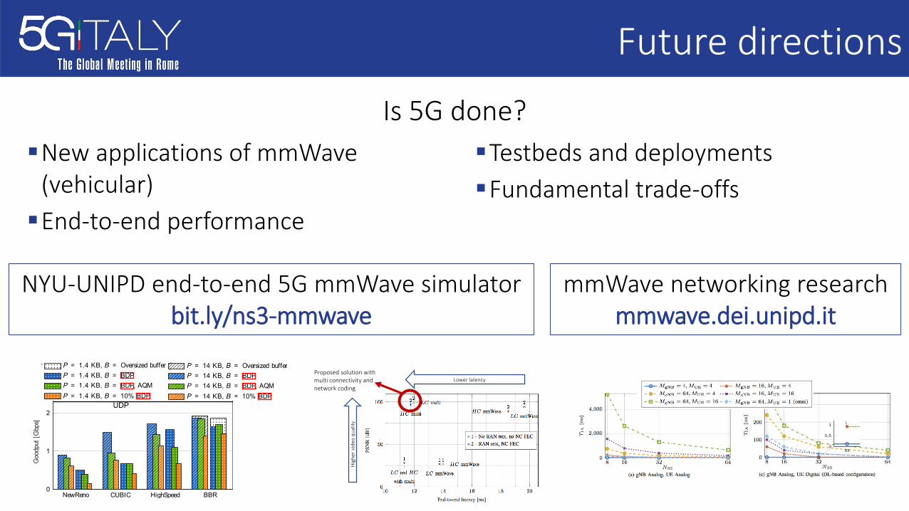
Future directions
�New applications of mmWave(vehicular)
�End-to-end performance
�Testbeds and deployments�Fundamental trade-offs
Is 5G done?
NYU-UNIPD end-to-end 5G mmWave simulatorbit.ly/ns3-mmwave
mmWave networking researchmmwave.dei.unipd.it
Lower latency
Hig
her
vide
o qu
ality
Proposed solution with multi connectivity and network coding
NewReno CUBIC HighSpeed BBR0
1
2UDP
Goodput[Gbps]
P = 14 KB, B = Oversized buffer P = 1.4 KB, B = Oversized bufferP = 14 KB, B = BDP P = 1.4 KB, B = BDPP = 14 KB, B = BDP, AQM P = 1.4 KB, B = BDP, AQMP = 14 KB, B = 10% BDP P = 1.4 KB, B = 10% BDP
NewReno CUBIC HighSpeed BBR0
20
40
60
80
100
no queuing delay
RTT[ms]
(a) Remote server.
NewReno CUBIC HighSpeed BBR0
1
2UDP
Goodput[Gbps]
NewReno CUBIC HighSpeed BBR0
2
4
6
8
10
no queuing delay
RTT[ms]
(b) Edge server.
Figure 2: Goodput and RTT for the high speed train scenario, with the remote and the edge server for different combinations of the buffer size and the MSS.
and is not affected by packet loss, i.e., the congestion windowdynamics of BBR, presented in Fig. 3a, matches the SINRplot in Fig. 1.However, the loss-based versions of TCP cannot adjust
their congestion window fast enough to adapt to the channelvariations and perform worse than BBR, especially with smallbuffer, as seen in Fig. 3a. Among them, TCP HighSpeed pro-vides the highest goodput because of the aggressive windowgrowth in the high BDP region. TCP CUBIC performs betterthan NewReno in the remote server case, but worse in theedgeserver case. This is because CUBIC’s window growth is notaffected by the ACK rate, and therefore is more reliable overlong RTT links.3) Impact of the MSS: The MSS does not affect the
performance of BBR, which probes the bandwidth with adifferent mechanism, whereas, for loss-based TCP, the impactof theMSS on the goodput is remarkable.3 The standard MSSof P = 1.4 KB exhibits much worse performance comparedto a larger MSS of P = 14 KB. This happens because, incongestion avoidance, the congestion window increases byMSSbytes every RTT, if all the packets are received correctlyand delayed acknowledgment is not used, so the smaller theMSS the slower the window growth. Hence, the MSS dictatesthe congestion window’s growth, which is particularly critical
3Typically, TCP segments are mapped to multiple MAC/PHY data units,which complicates the dependence between a larger value of the TCP MSSand the correspondingly higher packet error probability over thewireless link.This non-trivial relationship, which would deserve a study by itself, has beenproperly captured in our numerical results.
in mmWave networks for two main reasons: (i) ThemmWavepeak capacity is at least one order of magnitude higher than inLTE, so that the congestion window will take a much longertime to reach the achievable link rate. In this case, we can gainin performance by simply using a larger MSS, as depicted inFig. 2. (ii) In addition, thechannel fluctuations in themmWaveband will result in frequent quality drops, thus often requiringthe congestion window to quickly ramp up to the link capacityto avoid underutilizing the channel.Large MSS – mmWave vs. LTE: Aimed at better illus-
trating why larger packets are particularly important in 5GmmWave networks, we also provide a performance compari-son against LTE in the same scenario4, and report in Table Iand Fig. 3 detailed results focusing on the impact of the TCPMSS on the congestion window growth and, consequently, onthe goodput of the system. Only a single user is placed inthe high-speed train scenario, thus the drops in the congestionwindow are due to the worsening of the channel quality andnot to contention with other flows. Fig. 3 shows that the loss-based TCP congestion window with a small MSS grows veryslowly in congestion avoidance, and consequently loss-basedTCP does not fully exploit the available bandwidth duringthe intervals in which the received signal has a very highSINR (i.e., at t = 20 s and t = 40 s, as shown in Fig. 1).The large MSS helps speed up the congestion window’sgrowth, which translates into higher goodput. Conversely, the
4For the LTE setup the small buffer represents 50% of the BDP (i.e., 0.08and 0.2 MB for edge and remote server, respectively), because a 10% BDPbuffer would be too small to protect from random fluctuations of the channel.
NewReno CUBIC HighSpeed BBR0
1
2UDP
Goodput[Gbps]
P = 14 KB, B = Oversized buffer P = 1.4 KB, B = Oversized bufferP = 14 KB, B = BDP P = 1.4 KB, B = BDPP = 14 KB, B = BDP, AQM P = 1.4 KB, B = BDP, AQMP = 14 KB, B = 10% BDP P = 1.4 KB, B = 10% BDP
NewReno CUBIC HighSpeed BBR0
20
40
60
80
100
no queuing delay
RTT[ms]
(a) Remote server.
NewReno CUBIC HighSpeed BBR0
1
2UDP
Goodput[Gbps]
NewReno CUBIC HighSpeed BBR0
2
4
6
8
10
no queuing delay
RTT[ms]
(b) Edge server.
Figure 2: Goodput and RTT for the high speed train scenario, with the remote and the edge server for different combinations of the buffer size and the MSS.
and is not affected by packet loss, i.e., the congestion windowdynamics of BBR, presented in Fig. 3a, matches the SINRplot in Fig. 1.However, the loss-based versions of TCP cannot adjust
their congestion window fast enough to adapt to the channelvariations and perform worse than BBR, especially with smallbuffer, as seen in Fig. 3a. Among them, TCP HighSpeed pro-vides the highest goodput because of the aggressive windowgrowth in the high BDP region. TCP CUBIC performs betterthan NewReno in the remote server case, but worse in theedgeserver case. This is because CUBIC’s window growth is notaffected by the ACK rate, and therefore is more reliable overlong RTT links.3) Impact of the MSS: The MSS does not affect the
performance of BBR, which probes the bandwidth with adifferent mechanism, whereas, for loss-based TCP, the impactof theMSSon the goodput is remarkable.3 The standard MSSof P = 1.4 KB exhibits much worse performance comparedto a larger MSS of P = 14 KB. This happens because, incongestion avoidance, the congestion window increases byMSSbytes every RTT, if all the packets are received correctlyand delayed acknowledgment is not used, so the smaller theMSS the slower the window growth. Hence, the MSS dictatesthe congestion window’s growth, which is particularly critical
3Typically, TCP segments are mapped to multiple MAC/PHY data units,which complicates the dependence between a larger value of the TCP MSSand the correspondingly higher packet error probability over thewireless link.This non-trivial relationship, which would deserve a study by itself, has beenproperly captured in our numerical results.
in mmWave networks for two main reasons: (i) ThemmWavepeak capacity is at least one order of magnitude higher than inLTE, so that the congestion window will take a much longertime to reach theachievable link rate. In this case, wecan gainin performance by simply using a larger MSS, as depicted inFig. 2. (ii) In addition, thechannel fluctuations in themmWaveband will result in frequent quality drops, thus often requiringthe congestion window to quickly ramp up to the link capacityto avoid underutilizing the channel.Large MSS – mmWave vs. LTE: Aimed at better illus-
trating why larger packets are particularly important in 5GmmWave networks, we also provide a performance compari-son against LTE in the same scenario4, and report in Table Iand Fig. 3 detailed results focusing on the impact of the TCPMSS on the congestion window growth and, consequently, onthe goodput of the system. Only a single user is placed inthe high-speed train scenario, thus the drops in the congestionwindow are due to the worsening of the channel quality andnot to contention with other flows. Fig. 3 shows that the loss-based TCP congestion window with a small MSS grows veryslowly in congestion avoidance, and consequently loss-basedTCP does not fully exploit the available bandwidth duringthe intervals in which the received signal has a very highSINR (i.e., at t = 20 s and t = 40 s, as shown in Fig. 1).The large MSS helps speed up the congestion window’sgrowth, which translates into higher goodput. Conversely, the
4For the LTE setup the small buffer represents 50% of the BDP (i.e., 0.08and 0.2 MB for edge and remote server, respectively), because a 10% BDPbuffer would be too small to protect from random fluctuations of the channel.